EP3000169B1 - Input filter pre-charge fed by a medium-voltage grid supply - Google Patents
Input filter pre-charge fed by a medium-voltage grid supply Download PDFInfo
- Publication number
- EP3000169B1 EP3000169B1 EP13885323.9A EP13885323A EP3000169B1 EP 3000169 B1 EP3000169 B1 EP 3000169B1 EP 13885323 A EP13885323 A EP 13885323A EP 3000169 B1 EP3000169 B1 EP 3000169B1
- Authority
- EP
- European Patent Office
- Prior art keywords
- voltage
- charge
- modulation index
- input
- converter
- Prior art date
- Legal status (The legal status is an assumption and is not a legal conclusion. Google has not performed a legal analysis and makes no representation as to the accuracy of the status listed.)
- Revoked
Links
Images


Classifications
-
- H—ELECTRICITY
- H02—GENERATION; CONVERSION OR DISTRIBUTION OF ELECTRIC POWER
- H02M—APPARATUS FOR CONVERSION BETWEEN AC AND AC, BETWEEN AC AND DC, OR BETWEEN DC AND DC, AND FOR USE WITH MAINS OR SIMILAR POWER SUPPLY SYSTEMS; CONVERSION OF DC OR AC INPUT POWER INTO SURGE OUTPUT POWER; CONTROL OR REGULATION THEREOF
- H02M7/00—Conversion of ac power input into dc power output; Conversion of dc power input into ac power output
- H02M7/02—Conversion of ac power input into dc power output without possibility of reversal
- H02M7/04—Conversion of ac power input into dc power output without possibility of reversal by static converters
- H02M7/12—Conversion of ac power input into dc power output without possibility of reversal by static converters using discharge tubes with control electrode or semiconductor devices with control electrode
- H02M7/125—Avoiding or suppressing excessive transient voltages or currents
-
- H—ELECTRICITY
- H02—GENERATION; CONVERSION OR DISTRIBUTION OF ELECTRIC POWER
- H02M—APPARATUS FOR CONVERSION BETWEEN AC AND AC, BETWEEN AC AND DC, OR BETWEEN DC AND DC, AND FOR USE WITH MAINS OR SIMILAR POWER SUPPLY SYSTEMS; CONVERSION OF DC OR AC INPUT POWER INTO SURGE OUTPUT POWER; CONTROL OR REGULATION THEREOF
- H02M1/00—Details of apparatus for conversion
- H02M1/12—Arrangements for reducing harmonics from ac input or output
- H02M1/126—Arrangements for reducing harmonics from ac input or output using passive filters
-
- H—ELECTRICITY
- H02—GENERATION; CONVERSION OR DISTRIBUTION OF ELECTRIC POWER
- H02M—APPARATUS FOR CONVERSION BETWEEN AC AND AC, BETWEEN AC AND DC, OR BETWEEN DC AND DC, AND FOR USE WITH MAINS OR SIMILAR POWER SUPPLY SYSTEMS; CONVERSION OF DC OR AC INPUT POWER INTO SURGE OUTPUT POWER; CONTROL OR REGULATION THEREOF
- H02M1/00—Details of apparatus for conversion
- H02M1/32—Means for protecting converters other than automatic disconnection
-
- H—ELECTRICITY
- H02—GENERATION; CONVERSION OR DISTRIBUTION OF ELECTRIC POWER
- H02M—APPARATUS FOR CONVERSION BETWEEN AC AND AC, BETWEEN AC AND DC, OR BETWEEN DC AND DC, AND FOR USE WITH MAINS OR SIMILAR POWER SUPPLY SYSTEMS; CONVERSION OF DC OR AC INPUT POWER INTO SURGE OUTPUT POWER; CONTROL OR REGULATION THEREOF
- H02M1/00—Details of apparatus for conversion
- H02M1/36—Means for starting or stopping converters
-
- H—ELECTRICITY
- H02—GENERATION; CONVERSION OR DISTRIBUTION OF ELECTRIC POWER
- H02M—APPARATUS FOR CONVERSION BETWEEN AC AND AC, BETWEEN AC AND DC, OR BETWEEN DC AND DC, AND FOR USE WITH MAINS OR SIMILAR POWER SUPPLY SYSTEMS; CONVERSION OF DC OR AC INPUT POWER INTO SURGE OUTPUT POWER; CONTROL OR REGULATION THEREOF
- H02M7/00—Conversion of ac power input into dc power output; Conversion of dc power input into ac power output
- H02M7/02—Conversion of ac power input into dc power output without possibility of reversal
- H02M7/04—Conversion of ac power input into dc power output without possibility of reversal by static converters
- H02M7/12—Conversion of ac power input into dc power output without possibility of reversal by static converters using discharge tubes with control electrode or semiconductor devices with control electrode
- H02M7/21—Conversion of ac power input into dc power output without possibility of reversal by static converters using discharge tubes with control electrode or semiconductor devices with control electrode using devices of a triode or transistor type requiring continuous application of a control signal
- H02M7/217—Conversion of ac power input into dc power output without possibility of reversal by static converters using discharge tubes with control electrode or semiconductor devices with control electrode using devices of a triode or transistor type requiring continuous application of a control signal using semiconductor devices only
Definitions
- the present invention relates generally to the electric grid. More specifically, the present invention relates to reducing overvoltage and in-rush current in high power rectifier input filters used in medium-voltage grid applications.
- high power voltage source or current source rectifiers are normally fed by a medium voltage grid supply.
- An inductor capacitor (LC) input filter is used to feed the medium voltage grid supply.
- the LC input filter also assists the commutation process of related power devices and the filtering out of line current harmonics typically associated with high power rectification.
- the LC filter is designed to achieve a desired level of attenuation of the switching harmonics and to avoid the amplification of residual harmonics during normal operation.
- the input filter for high power rectifiers is lightly damped to avoid excessive power losses.
- the conventional pre-charge solution to this problem is to employ series-connected resistors to reduce both the over-voltage across the capacitors and the associated in-rush current.
- This solution requires the use of bulky pre-charge resistors. These bulky pre-charge resistors not only degrade the overall system efficiency, but leave limited space for optimization of the pre-charge of the input filter.
- JP 2006-340466 discloses a PWM converter controller.
- CN102916437 discloses a soft grid connection method of a grid-connected converter. The method is characterized in that the closed-loop control of the filtering capacitance and the filtering voltage is carried out synchronously; the current inter-loop control is added; and DC pre-charging return circuits are separated and boosted. According to the disclosure, a non-impact grid connection is realized without increasing great hardware complexity, thereby improving the reliability of the grid-connected converter.
- the present invention provides pre-charge circuit according to claim 1.
- the pre-charge circuit does not employ any pre-charge resistors to provide a smooth voltage rise over the filter capacitors and zero in-rush current at an AC-side.
- the pre-charge circuit can be preprogrammed to deliver constant and low power for the input filter pre-charge during the overall pre-charge process. This approach also uses a pre-charge transformer having a lower power rating. The lower power rating can be leveraged to lower overall system costs and improve overall system efficiency.
- the AC-side converter is controlled as an inverter during the pre-charge operation to generate a voltage across input filter capacitors which is synchronous with the grid supply voltage. In such manner, a smooth connection of the input filter to the medium-voltage grid supply can be achieved without the need for a clamping circuit to be placed across the input filter at the AC-side of the converter.
- the pre-charge power can be minimized by programming an appropriate modulation index profile, as discussed in further detail below.
- FIG. 1 is a schematic diagram illustration of a conventional pre-charge circuit 100 used to reduce overvoltage and in-rush current from a medium voltage AC grid supply 101.
- the pre-charge circuit 100 includes a connector (i.e., switch) 102 to control grid voltage supplied at a connector terminal 104.
- a damping resistor 106 is positioned in series with an input filter inductor 108 and an input filter capacitor 110.
- a two-level converter (e.g., rectifier) 112 provides one more output voltages at levels responsive to a DC pre-charge voltage supplied by a power source 115 via a pre-charge transformer 114.
- the pre-charge transformer 114 provides a DC link current (Idc) to charge a DC side capacitor 116 to drive a load 118, such as a motor, or other equipment.
- Idc DC link current
- a pre-charge circuit generally, is to minimize peak current output from a power source by eliminating overvoltage and/or reducing in-rush current.
- the system voltage rises slowly and controllably with the output current never exceeding the maximum allowable level.
- the medium level grid voltage, supplied by the grid 101, is suddenly received at the connector terminal 104 to initiate charging.
- the inductor 108 feeds the medium level AC voltage to the pre-charge circuit 100.
- the damping resistor 106 reduces the initial power-up surge, or in-rush current, and reduces the voltage stress applied to the input filter capacitor 110.
- the inductor 108, the damping resistor 106, and the capacitor 110 assist in the commutation process of related power devices to achieve the desired attenuation of switching harmonics. In so doing, amplification of residual harmonics, typically associated with high power rectification, can be avoided during normal operation. This conventional approach is loosely referred to as charging from the AC side.
- the pre-charge technique performed by the conventional pre-charge circuit 100 includes fairly significant deficiencies.
- the damping resistor 106 is typically very large and bulky, which ultimately increases the overall system costs.
- the bulky size of the damping resistor 106 also creates production inefficiencies due to the additional printed circuit board (PCB) real estate required to accommodate the resistor.
- the conventional pre-charge technique of FIG. 1 also prevents optimization of the pre-charge of the input filter.
- FIG. 2 is a block diagram illustration of an exemplary pre-charge circuit 200 constructed in accordance with an embodiment of the present invention.
- the pre-charge circuit 200 provides a totally controlled pre-charge without employing pre-charge resistors.
- the pre-charge circuit 200 includes an AC-side 200a and the DC side 200b, divided along a vertical line DL.
- the exemplary technique, achieved in the pre-charge circuit 200 also provides a smooth voltage rise and virtually zero in-rush current in response to a medium voltage grid supply 101.
- the approach of the exemplary embodiment of FIG. 2 ultimately reduces the overall system costs.
- the exemplary pre-charge circuit 200 includes a connection port 202, a contactor 204, and an inductor 206 connected in series with an input filter capacitor 208. These connections facilitate current flow between a multilevel AC/DC converter rectifier 210 and the medium voltage grid supply 101.
- a phase locked loop (PLL) 212 connected across connection port 202, includes two output ports.
- the first output port produces a grid supply voltage (Vs).
- the grid supply voltage Vs is combined with a filter capacitor voltage (Vc), in a combiner 214, and the combined voltage is provided as an input to a proportional-integral (PI) controller 216.
- PI proportional-integral
- the second output port of the PLL 212 provides phase data ⁇ s, associated with a waveform representative of the grid supply voltage Vs, as an input to a combiner 220.
- the phase data ⁇ s is combined with a local reference signal ⁇ /2 to produce a phase value ⁇ m.
- the phase value ⁇ m is provided as an input to a pulse width modulation (PWM) rectifier 222.
- PWM pulse width modulation
- a programmable modulation index module 224 produces a modulation index value M that is also provided as an input to the PWM rectifier 222.
- An output of the PWM rectifier 222 is provided as an input to the AC/DC converter rectifier 210.
- the programmable modulation index module 224 facilitates control of the modulation index M(t) of the converter rectifier 210, when the rectifier converter operates as an inverter. Standard computer system components, discussed more fully below, facilitate programmability of the modulation index module 224.
- the modulation index M(t) is controlled, along with an inverter firing angle.
- the inverter firing angle is equivalent to the phase value ⁇ m of the voltage waveform Vs.
- the PLL 212 provides an ability to synchronize phase data (e.g., ⁇ s) from waveforms representative of the grid AC voltage Vs and an equivalent of a voltage of the inverter.
- phase data e.g., ⁇ s
- the pre-charge circuit 200 instead of charging from the AC side, as achieved in the conventional pre-charge circuit 100 of FIG. 1 , the pre-charge circuit 200 provides pre-charging on the DC side 200b.
- the pre-charge circuit 200 uses a constant voltage transformer (CVT) 225 to perform the pre-charging (discussed more fully below).
- CVT constant voltage transformer
- This exemplary approach eliminates the need for damping resistors, such as the damping resistors 106 of FIG. 1 .
- the CVT transformer 225 of the pre-charge circuit 200 is relatively small in size in comparison to the damping resistors 106 of the conventional pre-charge circuit 100.
- pre-charging occurs during multistage process.
- a contactor 226 is closed.
- the pre-charge CVT 225 supplies a DC voltage (e.g., 220V RMS) from a DC power source 115.
- the CVT 225 delivers a nearly constant DC link current (Idc) to charge a DC-side capacitor 228.
- the DC link current Idc is required by the converter rectifier 210 to achieve normal operating conditions.
- the modulation index for the AC/DC converter rectifier 210 is desirably set to a maximum level M2.
- the pre-charge current (Iin) at the dc-side 200b from the CVT 225 is sufficiently high to ensure the filter capacitor voltage Vc substantially equals the grid supply voltage Vs at a modulation index M1, slightly less than the maximum modulation index value M2.
- an advantage offered in the illustrious embodiments is the ability to reduce the in-rush current flowing across the input filter capacitor 208, without the need for bulky damping resistors.
- the modulation index associated with the AC/DC converter rectifier 210 must be controlled. This control is achieved during a stage 2.
- the modulation index of the AC-DC rectifier 210 at grid-side will be soft-started. That is, at a time t2 (discussed more fully below), the modulation index begins to increase from zero to a final value Mf in accordance with a pre-programmable rule. This final value Mf can be programmed by a user to allow the DC-side 200b to deliver a nearly constant pre-charge power. After the modulation index reaches the final value Mf, the filter capacitor 208 will be reasonably close to the grid supply voltage Vs. During this mode, the AC/DC converter rectifier 210 operates as an inverter.
- the AC/DC converter rectifier 210 is used to increase the modulation index from zero to the modulation index M1, noted above.
- the PLL 212 is used to synchronize the grid side voltage amplitude Vs and phase ⁇ s. Once the amplitude Vs and phase ⁇ s information of the grid side is obtained, the AC/DC converter rectifier 210 can be used to charge the capacitor voltage Vc from a lower value to the grid supply voltage Vs, within a close measure of control.
- the capacitor voltage Vc will have a very small overshoot, if any, within the pre-charge condition.
- the modulation index can be preprogrammed to achieve constant power output during the pre-charge condition. In this way, the pre-charge CVT 225 can be optimally designed to achieve an optimal exchange of power with the filter capacitor 208.
- the modulation index reaches the final value Mf.
- the PI controller 216 which regulates the voltage error, is initialized.
- the integral part of the PI controller 216 desirably equals to the final modulation index, Mf, to enable fast PI loop control.
- the PI controller 216 can finally be used to adjust the modulation index to achieve a condition where Vc substantially equals Vs.
- the PI controller 216 regulates the capacitor voltage Vc.
- the purpose is to control the modulation index to maintain the capacitor voltage Vc close to the grid supply voltage Vs.
- stage 4 when Vc substantially equals Vs, the contactor 204 closes. Since the Vs amplitude and phase are synchronized, a supply current Is remains zero. At the same time, the PI controller 216 is disabled and the modulation index of the PWM rectifier 222 is gradually reduced to zero over this stage, while the dc-link current Idc is kept constant by the pre-charge converter 210.
- the power supplied to the filter capacitor 208 will be transferred from the PWM rectifier 222 to the AC/DC converter rectifier 210.
- the amplitude of the supply current Is increases as the amplitude of the current provided by the PWM rectifier 222 decreases according to the pre-programmed modulation index.
- the preprogrammed modulation index facilitates a smooth increase of the supply current Is from the medium voltage grid supply 101.
- Vc is substantially equal to Vs so there is no in-rush current flowing through the input filter 200.
- the preprogrammed value is used to enable the current Il to flow through the inductor 206 so that the current Il can be gradually increased from zero to the nominal operating value. Also, the voltage across the capacitor can be smoothly increased and decreased.
- stage 5 once the modulation index has reached zero, the CVT 25 can be disabled by opening the contactor 226. At this time, the input filter 200 is fully supplied by the utility medium voltage grid 101 and the converter 210 will operate on its own as the CVT pre-charge transformer will be isolated from the remaining portion of the DC-side 200b.
- FIG. 3 is a graphical illustration of an exemplary timing diagram 300 in association with the illustration of FIG 2 . More specifically, the timing diagram 300 provides a timing correlation between stages 1-5, discussed above, and various components within the exemplary pre-charge circuit 300, along a timeline 302.
- DC link current Idc 304 and pre-charge power 306 are both zero.
- the pre-charge power 306 is indicative of an amount of power delivered from the pre-charge CVT 225.
- An optimal minimal pre-charge power 306 is sought such that required voltage and size of the CVT 225 can be minimized.
- the contactor 226 is closed and the pre-charge scheme of the pre-charge circuit 200 begins. More specifically, when the contactor 226 is closed, the CVT 225 begins to charge the DC-side capacitor 228. The DC side capacitor 228 continues to charge to the required DC link voltage until a time t2.
- the modulation index M(t) 308 of the AC/DC rectifier 210 is preprogrammed to soft start via the modulation index module 224.
- the modulation index begins increasing from zero to the final value Mf (e.g., achieved at t3) according to preprogrammed instructions.
- the preprogrammed instructions enable the DC-side to deliver a nearly constant pre-charge power 306, as illustrated in FIG. 3 . This process continues until commencement of stage 3, at time t3.
- the time lapse between t2 and t3 is referred to herein as a time quanta.
- capacitor voltage Vab 310 which is equivalent to the line voltage between a phase A and phase B, is indicative of how phase voltage is charged from zero to a specified value. That is, during stage 2, the modulation index M is in the soft start mode and will be gradually increased from zero to the normal operating value.
- the capacitor voltage Vab 310 begins to increase from zero to the specified value without any significant overshooting. Once the process transitions to stage 3 at t3, the voltage will continue to rise slightly, eventually achieving the specified value.
- the controlled modulation index is responsive to closed loop control to maintain the filter capacitor voltage Vc, through closed loop control, to be substantially equal to the grid supply voltage Vs.
- stage 4 the modulation index will slowly fall below the normal operating value to zero. During this transition, the modulation index of stage 4 mirrors the modulation index of stage 2. Also during stage 4, the grid current Is 312 increases from zero to a maximum value, achieved at t5. This increase occurs because the modulation M index generated by the AC/DC converter rectifier 210 will drop from maximum value to zero, which means there will be no power delivered from the DC-side 200b to the AC-side 200a.
- the filter capacitor 208 can be closed through use of contactor 204, such that the grid power 306 will flow to the grid to deliver through the AC/DC converter 210. In this manner, the current will be gradually increased because the modulation index M generated by the AC/DC converter rectifier 210 is gradually decreased from maximum value to zero value.
- This process represents a balance of the power between the grid side 200b and the energy generated from the grid side converter. More specifically, the power generated by the AC/DC converter rectifier 210 was reduced so there will be more power generated from the grid - achievement of an ultimate balance.
- the AC/DC converter rectifier 210 can be disabled by opening the contactor 226. At this point, the pre-charge circuit 200 is fully supplied by the medium voltage grid supply 101.
- FIG. 4 is a flowchart of an exemplary method 400 of practicing an embodiment of the present invention.
- a pre-charge voltage is supplied to a capacitor via a transformer, in step 402.
- an AC voltage is converted to DC voltage within the transformer, the converting being responsive to a modulation index.
- a time quanta commences. During the time quanta, the modulation index increases and the pre-charge voltage remains substantially constant.
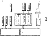
- FIG. 5 is an illustration of an example computer system 500 in which embodiments of the present invention, or portions thereof, can be implemented as computer-readable code.
- the method illustrated by flowchart 100 of FIG. 2 can be implemented in computer system 500.
- Various embodiments of the present invention are described in terms of this example computer system 500. After reading this description, it will become apparent to a person of ordinary skill in the relevant art how to implement embodiments of the present invention using other computer systems and/or computer architectures.
- Computer system 500 includes one or more processors, such as processor 504.
- Processor 504 may be a special purpose or a general purpose processor.
- Processor 504 is connected to a communication infrastructure 506 (e.g., a bus or network).
- Computer system 500 also includes a main memory 508, preferably random access memory (RAM), and may also include a secondary memory 510.
- Secondary memory 510 can include, for example, a hard disk drive 512, a removable storage drive 514, and/or a memory stick.
- Removable storage drive 514 can include a floppy disk drive, a magnetic tape drive, an optical disk drive, a flash memory, or the like. The removable storage drive 514 reads from and/or writes to a removable storage unit 518 in a well known manner.
- Removable storage unit 518 can comprise a floppy disk, magnetic tape, optical disk, etc. which is read by and written to by removable storage drive 514.
- removable storage unit 518 includes a computer-usable storage medium having stored therein computer software and/or data.
- secondary memory 510 can include other similar devices for allowing computer programs or other instructions to be loaded into computer system 500.
- Such devices can include, for example, a removable storage unit 522 and an interface 520.
- Examples of such devices can include a program cartridge and cartridge interface (such as those found in video game devices), a removable memory chip (e.g., EPROM or PROM) and associated socket, and other removable storage units 522 and interfaces 520 which allow software and data to be transferred from the removable storage unit 522 to computer system 500.
- Computer system 500 can also include a communications interface 524.
- Communications interface 524 allows software and data to be transferred between computer system 500 and external devices.
- Communications interface 524 can include a modem, a network interface (such as an Ethernet card), a communications port, or the like.
- Software and data transferred via communications interface 524 are in the form of signals, which may be electronic, electromagnetic, optical, or other signals capable of being received by communications interface 524. These signals are provided to communications interface 524 via a communications path 526.
- Communications path 526 carries signals and can be implemented using wire or cable, fiber optics, a phone line, a cellular phone link, a radio frequency (RF) link or other communications channels.
- RF radio frequency
- computer program medium and “computer-usable medium” are used to generally refer to media such as removable storage unit 518, removable storage unit 522, and a hard disk installed in hard disk drive 512.
- Computer program medium and computer-usable medium can also refer to memories, such as main memory 508 and secondary memory 510, which can be memory semiconductors (e.g., DRAMs, etc.). These computer program products provide software to computer system 500.
- Computer programs are stored in main memory 508 and/or secondary memory 510. Computer programs may also be received via communications interface 524. Such computer programs, when executed, enable computer system 500 to implement embodiments of the present invention as discussed herein. In particular, the computer programs, when executed, enable processor 504 to implement processes of embodiments of the present invention. Accordingly, such computer programs represent controllers of the computer system 500. Where embodiments of the present invention are implemented using software, the software can be stored in a computer program product and loaded into computer system 500 using removable storage drive 514, interface 520, hard drive 512, or communications interface 524.
- embodiments of the present invention provide The proposed input filter pre-charge achieves the commercial benefits of a smoother and programmable connection of the LC filter to the grid supply; eliminates the need for the pre-charge resistor and in additional contactor, which is a cost-saving solution for high power applications.
- the embodiments also eliminate in-rush current and over-voltage across the filter capacitor, enabling the achievement of an optimized and controllable pre-charge profile.
- various aspects of the present invention can be implemented by software, firmware, hardware (or hardware represented by software such, as for example, Verilog or hardware description language instructions), or a combination thereof.
- software firmware
- hardware or hardware represented by software such, as for example, Verilog or hardware description language instructions
Landscapes
- Engineering & Computer Science (AREA)
- Power Engineering (AREA)
- Rectifiers (AREA)
- Dc-Dc Converters (AREA)
Description
- The present invention relates generally to the electric grid. More specifically, the present invention relates to reducing overvoltage and in-rush current in high power rectifier input filters used in medium-voltage grid applications.
- In the generation, transmission, and distribution of conventional electrical power, power is transmitted over long distances, via the electric grid, at high alternating current (AC) voltages. In some cases, and for various reasons, these high AC voltages must be transmitted as high direct current (DC) voltages. A fundamental principle of DC transmission is using a rectifier to transform the AC voltages to DC voltages. High power voltage source, or current source, rectifiers are often used in this process.
- As understood by those of skill in the art, high power voltage source or current source rectifiers are normally fed by a medium voltage grid supply. An inductor capacitor (LC) input filter is used to feed the medium voltage grid supply. The LC input filter also assists the commutation process of related power devices and the filtering out of line current harmonics typically associated with high power rectification.
- More specifically, the LC filter is designed to achieve a desired level of attenuation of the switching harmonics and to avoid the amplification of residual harmonics during normal operation. However, for high power applications, the input filter for high power rectifiers is lightly damped to avoid excessive power losses.
- Inherent power losses in the input filter and the supply transformer provide a minimum degree of damping. Such a low inherent damping factor of the input LC filter usually results in the excessive over-voltage stress across the input filter capacitors followed by a direct connection of the input filter to the medium-voltage grid supply.
- The conventional pre-charge solution to this problem is to employ series-connected resistors to reduce both the over-voltage across the capacitors and the associated in-rush current. This solution, however, requires the use of bulky pre-charge resistors. These bulky pre-charge resistors not only degrade the overall system efficiency, but leave limited space for optimization of the pre-charge of the input filter.
- Other conventional pre-charge solutions employ additional pre-charge circuit components such as the pre-charge resistor and contactors, resulting in increased system costs and diminish overall system efficiency. These undesirable consequences are especially applicable to high power AC-DC converters directly fed by a medium-voltage grid supply (e.g: 6kV+). For worst case here, the in-rush current results in serve current distortions at the grid terminal if the pre-charge resistor is not heavy damped.
- Other conventional solutions include use an AC side pre-charge instead of a DC side pre-charge. Use of an AC side pre-charge instead of a DC-side pre-charge, however, faces the challenge of having the filter capacitor assume a very small value. The small filter capacitor value creates a correspondingly small impedance formed the connection from each phase to the ground. Therefore, this approach also fails to eliminate the in-rush current and over- voltage.
-
JP 2006-340466 CN102916437 discloses a soft grid connection method of a grid-connected converter. The method is characterized in that the closed-loop control of the filtering capacitance and the filtering voltage is carried out synchronously; the current inter-loop control is added; and DC pre-charging return circuits are separated and boosted. According to the disclosure, a non-impact grid connection is realized without increasing great hardware complexity, thereby improving the reliability of the grid-connected converter. - Given the aforementioned deficiencies, a need exists for methods and systems to eliminate the need of bulky pre-charge resistors to reduce the over-voltage stress and in-rush current across input filter capacitors. More specifically, methods and systems are needed to facilitate a smooth voltage rise and zero in-rush current when connecting to a medium-voltage grid supply. The present invention provides pre-charge circuit according to
claim 1. - The pre-charge circuit does not employ any pre-charge resistors to provide a smooth voltage rise over the filter capacitors and zero in-rush current at an AC-side. The pre-charge circuit can be preprogrammed to deliver constant and low power for the input filter pre-charge during the overall pre-charge process. This approach also uses a pre-charge transformer having a lower power rating. The lower power rating can be leveraged to lower overall system costs and improve overall system efficiency.
- The AC-side converter is controlled as an inverter during the pre-charge operation to generate a voltage across input filter capacitors which is synchronous with the grid supply voltage. In such manner, a smooth connection of the input filter to the medium-voltage grid supply can be achieved without the need for a clamping circuit to be placed across the input filter at the AC-side of the converter. The pre-charge power can be minimized by programming an appropriate modulation index profile, as discussed in further detail below.
- Further features and advantages of the invention, as well as the structure and operation of various embodiments of the invention, are described in detail below with reference to the accompanying drawings. It is noted that the invention is not limited to the specific embodiments described herein. Such embodiments are presented herein for illustrative purposes only. Additional embodiments will be apparent to persons skilled in the relevant art(s) based on the teachings contained herein.
- The accompanying drawings, which are incorporated herein and form part of the specification, illustrate the present invention and, together with the description, further serve to explain the principles of the invention and to enable a person skilled in the relevant art(s) to make and use the invention.
-
FIG. 1 is a schematic diagram illustration of a conventional pre-charge input filter circuit used to reduce overvoltage and in-rush current. -
FIG. 2 is a block diagram illustration of an exemplary pre-charge input filter circuit constructed in accordance with an embodiment of the present invention. -
FIG. 3 is a graphical illustration of an exemplary timing diagram in association with the illustration ofFIG 2 . -
FIG. 4 is a flowchart of an exemplary method of practicing an embodiment of the present invention. -
FIG. 5 is an illustration of an exemplary computer system in which embodiments of the present invention can be implemented. - While the present invention is described herein with illustrative embodiments for particular applications, it should be understood that the invention is not limited thereto. Those skilled in the art with access to the teachings provided herein will recognize additional modifications, applications, and embodiments within the scope thereof and additional fields in which the invention would be of significant utility.
-
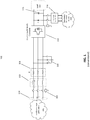
FIG. 1 is a schematic diagram illustration of a conventionalpre-charge circuit 100 used to reduce overvoltage and in-rush current from a medium voltageAC grid supply 101. Thepre-charge circuit 100 includes a connector (i.e., switch) 102 to control grid voltage supplied at aconnector terminal 104. Adamping resistor 106 is positioned in series with aninput filter inductor 108 and aninput filter capacitor 110. - A two-level converter (e.g., rectifier) 112 provides one more output voltages at levels responsive to a DC pre-charge voltage supplied by a
power source 115 via apre-charge transformer 114. Once the pre-charge process has been completed, thepre-charge transformer 114 provides a DC link current (Idc) to charge aDC side capacitor 116 to drive aload 118, such as a motor, or other equipment. - As understood by those of skill in the art, the purpose of a pre-charge circuit, generally, is to minimize peak current output from a power source by eliminating overvoltage and/or reducing in-rush current. During pre-charging, the system voltage rises slowly and controllably with the output current never exceeding the maximum allowable level.
- For example, during operation of the conventional
pre-charge circuit 100, when theconnector 102 is closed, the medium level grid voltage, supplied by thegrid 101, is suddenly received at theconnector terminal 104 to initiate charging. Theinductor 108 feeds the medium level AC voltage to thepre-charge circuit 100. The dampingresistor 106 reduces the initial power-up surge, or in-rush current, and reduces the voltage stress applied to theinput filter capacitor 110. - As noted above, the
inductor 108, the dampingresistor 106, and thecapacitor 110 assist in the commutation process of related power devices to achieve the desired attenuation of switching harmonics. In so doing, amplification of residual harmonics, typically associated with high power rectification, can be avoided during normal operation. This conventional approach is loosely referred to as charging from the AC side. - The pre-charge technique performed by the conventional
pre-charge circuit 100, however, includes fairly significant deficiencies. For example, the dampingresistor 106 is typically very large and bulky, which ultimately increases the overall system costs. The bulky size of the dampingresistor 106 also creates production inefficiencies due to the additional printed circuit board (PCB) real estate required to accommodate the resistor. The conventional pre-charge technique ofFIG. 1 also prevents optimization of the pre-charge of the input filter. -
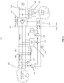
FIG. 2 is a block diagram illustration of an exemplarypre-charge circuit 200 constructed in accordance with an embodiment of the present invention. Thepre-charge circuit 200 provides a totally controlled pre-charge without employing pre-charge resistors. Thepre-charge circuit 200 includes an AC-side 200a and theDC side 200b, divided along a vertical line DL. The exemplary technique, achieved in thepre-charge circuit 200, also provides a smooth voltage rise and virtually zero in-rush current in response to a mediumvoltage grid supply 101. The approach of the exemplary embodiment ofFIG. 2 ultimately reduces the overall system costs. - The exemplary
pre-charge circuit 200 includes aconnection port 202, acontactor 204, and aninductor 206 connected in series with aninput filter capacitor 208. These connections facilitate current flow between a multilevel AC/DC converter rectifier 210 and the mediumvoltage grid supply 101. - A phase locked loop (PLL) 212, connected across
connection port 202, includes two output ports. The first output port produces a grid supply voltage (Vs). The grid supply voltage Vs is combined with a filter capacitor voltage (Vc), in acombiner 214, and the combined voltage is provided as an input to a proportional-integral (PI)controller 216. Avoltage sensor 218, connected in series with theinput filter capacitor 208, senses the capacitor voltage and provides Vc as an output therefrom. - The second output port of the
PLL 212 provides phase data θs, associated with a waveform representative of the grid supply voltage Vs, as an input to acombiner 220. The phase data θs is combined with a local reference signal π/2 to produce a phase value θm. The phase value θm is provided as an input to a pulse width modulation (PWM)rectifier 222. A programmablemodulation index module 224 produces a modulation index value M that is also provided as an input to thePWM rectifier 222. An output of thePWM rectifier 222 is provided as an input to the AC/DC converter rectifier 210. - The programmable
modulation index module 224 facilitates control of the modulation index M(t) of theconverter rectifier 210, when the rectifier converter operates as an inverter. Standard computer system components, discussed more fully below, facilitate programmability of themodulation index module 224. - When the
converter rectifier 210 operates as an inverter, the modulation index M(t) is controlled, along with an inverter firing angle. The inverter firing angle is equivalent to the phase value θm of the voltage waveform Vs. - In the exemplary
pre-charge circuit 200, thePLL 212 provides an ability to synchronize phase data (e.g., θs) from waveforms representative of the grid AC voltage Vs and an equivalent of a voltage of the inverter. - In the exemplary embodiment of
FIG. 2 , instead of charging from the AC side, as achieved in the conventionalpre-charge circuit 100 ofFIG. 1 , thepre-charge circuit 200 provides pre-charging on theDC side 200b. Thepre-charge circuit 200 uses a constant voltage transformer (CVT) 225 to perform the pre-charging (discussed more fully below). This exemplary approach eliminates the need for damping resistors, such as the dampingresistors 106 ofFIG. 1 . TheCVT transformer 225 of thepre-charge circuit 200 is relatively small in size in comparison to the dampingresistors 106 of the conventionalpre-charge circuit 100. - During an exemplary operational scenario, pre-charging occurs during multistage process. During
stage 1, acontactor 226 is closed. Upon closure of thecontactor 226, thepre-charge CVT 225 supplies a DC voltage (e.g., 220V RMS) from aDC power source 115. During this stage, theCVT 225 delivers a nearly constant DC link current (Idc) to charge a DC-side capacitor 228. The DC link current Idc is required by theconverter rectifier 210 to achieve normal operating conditions. - The modulation index for the AC/
DC converter rectifier 210 is desirably set to a maximum level M2. The pre-charge current (Iin) at the dc-side 200b from theCVT 225 is sufficiently high to ensure the filter capacitor voltage Vc substantially equals the grid supply voltage Vs at a modulation index M1, slightly less than the maximum modulation index value M2. - As noted above, an advantage offered in the illustrious embodiments is the ability to reduce the in-rush current flowing across the
input filter capacitor 208, without the need for bulky damping resistors. In the embodiments, to reduce the in-rush current flowing through theinput filter capacitor 208, the modulation index associated with the AC/DC converter rectifier 210 must be controlled. This control is achieved during astage 2. - More specifically, in
stage 2, once the DC-side capacitor 228 is charged to the rated dc-link voltage, the modulation index of the AC-DC rectifier 210 at grid-side will be soft-started. That is, at a time t2 (discussed more fully below), the modulation index begins to increase from zero to a final value Mf in accordance with a pre-programmable rule. This final value Mf can be programmed by a user to allow the DC-side 200b to deliver a nearly constant pre-charge power. After the modulation index reaches the final value Mf, thefilter capacitor 208 will be reasonably close to the grid supply voltage Vs. During this mode, the AC/DC converter rectifier 210 operates as an inverter. - In order for the
filter capacitor 208 to be charged close to the grid supply voltage Vs, the AC/DC converter rectifier 210 is used to increase the modulation index from zero to the modulation index M1, noted above. - The
PLL 212 is used to synchronize the grid side voltage amplitude Vs and phase θs. Once the amplitude Vs and phase θs information of the grid side is obtained, the AC/DC converter rectifier 210 can be used to charge the capacitor voltage Vc from a lower value to the grid supply voltage Vs, within a close measure of control. - Using this approach, the capacitor voltage Vc will have a very small overshoot, if any, within the pre-charge condition. Additionally, the modulation index can be preprogrammed to achieve constant power output during the pre-charge condition. In this way, the
pre-charge CVT 225 can be optimally designed to achieve an optimal exchange of power with thefilter capacitor 208. - During
stage 3, the modulation index reaches the final value Mf. When the modulation index reaches the final value mf, thePI controller 216, which regulates the voltage error, is initialized. The integral part of thePI controller 216 desirably equals to the final modulation index, Mf, to enable fast PI loop control. ThePI controller 216 can finally be used to adjust the modulation index to achieve a condition where Vc substantially equals Vs. - That is, once the modulation index reaches the operating final value Mf, the
PI controller 216 regulates the capacitor voltage Vc. The purpose is to control the modulation index to maintain the capacitor voltage Vc close to the grid supply voltage Vs. - In
stage 4, when Vc substantially equals Vs, thecontactor 204 closes. Since the Vs amplitude and phase are synchronized, a supply current Is remains zero. At the same time, thePI controller 216 is disabled and the modulation index of thePWM rectifier 222 is gradually reduced to zero over this stage, while the dc-link current Idc is kept constant by thepre-charge converter 210. - Also during
stage 4, the power supplied to thefilter capacitor 208 will be transferred from thePWM rectifier 222 to the AC/DC converter rectifier 210. The amplitude of the supply current Is increases as the amplitude of the current provided by thePWM rectifier 222 decreases according to the pre-programmed modulation index. The preprogrammed modulation index facilitates a smooth increase of the supply current Is from the mediumvoltage grid supply 101. - Additionally, when the
contactor 204 is closed, the current Il flowing through theinductor 206 will be gradually increased from zero to a nominal operating value. Vc is substantially equal to Vs so there is no in-rush current flowing through theinput filter 200. - The preprogrammed value is used to enable the current Il to flow through the
inductor 206 so that the current Il can be gradually increased from zero to the nominal operating value. Also, the voltage across the capacitor can be smoothly increased and decreased. - In
stage 5, once the modulation index has reached zero, the CVT 25 can be disabled by opening thecontactor 226. At this time, theinput filter 200 is fully supplied by the utilitymedium voltage grid 101 and theconverter 210 will operate on its own as the CVT pre-charge transformer will be isolated from the remaining portion of the DC-side 200b. -
FIG. 3 is a graphical illustration of an exemplary timing diagram 300 in association with the illustration ofFIG 2 . More specifically, the timing diagram 300 provides a timing correlation between stages 1-5, discussed above, and various components within the exemplarypre-charge circuit 300, along atimeline 302. - During
stage 1, for example, at a time t0 along thetimeline 302, DC linkcurrent Idc 304 andpre-charge power 306 are both zero. Thepre-charge power 306 is indicative of an amount of power delivered from thepre-charge CVT 225. An optimal minimalpre-charge power 306 is sought such that required voltage and size of theCVT 225 can be minimized. - At time t1, the
contactor 226 is closed and the pre-charge scheme of thepre-charge circuit 200 begins. More specifically, when thecontactor 226 is closed, theCVT 225 begins to charge the DC-side capacitor 228. TheDC side capacitor 228 continues to charge to the required DC link voltage until a time t2. - At t2 during
stage 2, after theDC side capacitor 228 reaches the required link voltage and theDC side capacitor 228 is fully charged, the modulation index M(t) 308 of the AC/DC rectifier 210 is preprogrammed to soft start via themodulation index module 224. - As noted above, at time t2, the modulation index begins increasing from zero to the final value Mf (e.g., achieved at t3) according to preprogrammed instructions. The preprogrammed instructions enable the DC-side to deliver a nearly constant
pre-charge power 306, as illustrated inFIG. 3 . This process continues until commencement ofstage 3, at time t3. The time lapse between t2 and t3 is referred to herein as a time quanta. - Also at time t2,
capacitor voltage Vab 310, which is equivalent to the line voltage between a phase A and phase B, is indicative of how phase voltage is charged from zero to a specified value. That is, duringstage 2, the modulation index M is in the soft start mode and will be gradually increased from zero to the normal operating value. Thecapacitor voltage Vab 310 begins to increase from zero to the specified value without any significant overshooting. Once the process transitions to stage 3 at t3, the voltage will continue to rise slightly, eventually achieving the specified value. - During time t3, the controlled modulation index is responsive to closed loop control to maintain the filter capacitor voltage Vc, through closed loop control, to be substantially equal to the grid supply voltage Vs.
- During
stage 4 at time t4, the modulation index will slowly fall below the normal operating value to zero. During this transition, the modulation index ofstage 4 mirrors the modulation index ofstage 2. Also duringstage 4, the grid current Is 312 increases from zero to a maximum value, achieved at t5. This increase occurs because the modulation M index generated by the AC/DC converter rectifier 210 will drop from maximum value to zero, which means there will be no power delivered from the DC-side 200b to the AC-side 200a. - Since the
capacitor voltage Vab 310 was left to be charged to the grid supply voltage Vs, thefilter capacitor 208 can be closed through use ofcontactor 204, such that thegrid power 306 will flow to the grid to deliver through the AC/DC converter 210. In this manner, the current will be gradually increased because the modulation index M generated by the AC/DC converter rectifier 210 is gradually decreased from maximum value to zero value. - This process represents a balance of the power between the
grid side 200b and the energy generated from the grid side converter. More specifically, the power generated by the AC/DC converter rectifier 210 was reduced so there will be more power generated from the grid - achievement of an ultimate balance. - Once the modulation index M reaches zero at t5, the AC/
DC converter rectifier 210 can be disabled by opening thecontactor 226. At this point, thepre-charge circuit 200 is fully supplied by the mediumvoltage grid supply 101. -
FIG. 4 is a flowchart of anexemplary method 400 of practicing an embodiment of the present invention. - During the
method 400, a pre-charge voltage is supplied to a capacitor via a transformer, instep 402. Instep 404, an AC voltage is converted to DC voltage within the transformer, the converting being responsive to a modulation index. When the capacitor becomes substantially fully charge charged, a time quanta commences. During the time quanta, the modulation index increases and the pre-charge voltage remains substantially constant. - Various aspects of the present invention may be implemented in software, firmware, hardware, or a combination thereof.
Figure 5 is an illustration of anexample computer system 500 in which embodiments of the present invention, or portions thereof, can be implemented as computer-readable code. For example, the method illustrated byflowchart 100 ofFIG. 2 can be implemented incomputer system 500. Various embodiments of the present invention are described in terms of thisexample computer system 500. After reading this description, it will become apparent to a person of ordinary skill in the relevant art how to implement embodiments of the present invention using other computer systems and/or computer architectures. -
Computer system 500 includes one or more processors, such asprocessor 504.Processor 504 may be a special purpose or a general purpose processor.Processor 504 is connected to a communication infrastructure 506 (e.g., a bus or network). -
Computer system 500 also includes amain memory 508, preferably random access memory (RAM), and may also include asecondary memory 510.Secondary memory 510 can include, for example, ahard disk drive 512, aremovable storage drive 514, and/or a memory stick.Removable storage drive 514 can include a floppy disk drive, a magnetic tape drive, an optical disk drive, a flash memory, or the like. Theremovable storage drive 514 reads from and/or writes to aremovable storage unit 518 in a well known manner. -
Removable storage unit 518 can comprise a floppy disk, magnetic tape, optical disk, etc. which is read by and written to byremovable storage drive 514. As will be appreciated by persons skilled in the relevant art,removable storage unit 518 includes a computer-usable storage medium having stored therein computer software and/or data. - In alternative implementations,
secondary memory 510 can include other similar devices for allowing computer programs or other instructions to be loaded intocomputer system 500. Such devices can include, for example, aremovable storage unit 522 and aninterface 520. Examples of such devices can include a program cartridge and cartridge interface (such as those found in video game devices), a removable memory chip (e.g., EPROM or PROM) and associated socket, and otherremovable storage units 522 andinterfaces 520 which allow software and data to be transferred from theremovable storage unit 522 tocomputer system 500. -
Computer system 500 can also include acommunications interface 524. Communications interface 524 allows software and data to be transferred betweencomputer system 500 and external devices. Communications interface 524 can include a modem, a network interface (such as an Ethernet card), a communications port, or the like. Software and data transferred viacommunications interface 524 are in the form of signals, which may be electronic, electromagnetic, optical, or other signals capable of being received bycommunications interface 524. These signals are provided tocommunications interface 524 via acommunications path 526.Communications path 526 carries signals and can be implemented using wire or cable, fiber optics, a phone line, a cellular phone link, a radio frequency (RF) link or other communications channels. - In this document, the terms "computer program medium" and "computer-usable medium" are used to generally refer to media such as
removable storage unit 518,removable storage unit 522, and a hard disk installed inhard disk drive 512. Computer program medium and computer-usable medium can also refer to memories, such asmain memory 508 andsecondary memory 510, which can be memory semiconductors (e.g., DRAMs, etc.). These computer program products provide software tocomputer system 500. - Computer programs (also called computer control logic) are stored in
main memory 508 and/orsecondary memory 510. Computer programs may also be received viacommunications interface 524. Such computer programs, when executed, enablecomputer system 500 to implement embodiments of the present invention as discussed herein. In particular, the computer programs, when executed, enableprocessor 504 to implement processes of embodiments of the present invention. Accordingly, such computer programs represent controllers of thecomputer system 500. Where embodiments of the present invention are implemented using software, the software can be stored in a computer program product and loaded intocomputer system 500 usingremovable storage drive 514,interface 520,hard drive 512, orcommunications interface 524. - As noted above, embodiments of the present invention provide The proposed input filter pre-charge achieves the commercial benefits of a smoother and programmable connection of the LC filter to the grid supply; eliminates the need for the pre-charge resistor and in additional contactor, which is a cost-saving solution for high power applications. The embodiments also eliminate in-rush current and over-voltage across the filter capacitor, enabling the achievement of an optimized and controllable pre-charge profile.
- The present invention has been described above with the aid of functional building blocks illustrating the implementation of specified functions and relationships thereof. The boundaries of these functional building blocks have been arbitrarily defined herein for the convenience of the description. Alternate boundaries can be defined so long as the specified functions and relationships thereof are appropriately performed.
- For example, various aspects of the present invention can be implemented by software, firmware, hardware (or hardware represented by software such, as for example, Verilog or hardware description language instructions), or a combination thereof. After reading this description, it will become apparent to a person skilled in the relevant art how to implement the invention using other computer systems and/or computer architectures.
- It is to be appreciated that the Detailed Description section, and not the Summary and Abstract sections, is intended to be used to interpret the claims. The Summary and Abstract sections may set forth one or more but not all exemplary embodiments of the present invention as contemplated by the inventor(s), and thus, are not intended to limit the present invention and the appended claims in any way.
Claims (2)
- A pre-charge circuit (200), comprising:a direct current DC link electrically coupleable to a load (116) and including a DC link capacitor (228);a pre-charge transformer (225) and a contactor (226), wherein the pre-charge transformer (225) is electrically coupled to the DC link by means of the contactor (226) and configured to supply a pre-charge voltage to the DC link capacitor (228);a converter (210) having a DC side electrically coupled to the transformer (225) by means of the DC link and an alternating current AC side;an input filter comprising an inductor (206) and a filter capacitor (208) connected in series for each AC phase, wherein the inductor (206) and the filter capacitor (208) are electrically coupled to the AC side of the converter (210) and the input filter is devoid of damping resistors;a connection port (202) and an AC circuit, wherein the connection port (202) is electrically coupleable to an AC voltage supply (101) and electrically coupled to the inductors (206) of the input filter by means of the AC circuit, which includes a contactor (204);a pulse width modulation PWM generator (222), wherein an output of the PWM generator (222) is provided as an input to the converter (210) for controlling modulation index and inverter firing angle of the converter (210) when the converter (210) is operated as an inverter;a phase locked loop PLL (212), a first combiner (220), a second combiner (214), a voltage sensor (218) and a proportional-integral PI controller (216), wherein the phase locked loop PLL (212) is electrically coupled to the AC circuit and is configured to provide:(i) phase data associated with a waveform representative of the grid supply voltage as an input to the first combiner (220), which is configured to combine the phase data with a local reference signal π/2 to produce a phase value that is provided as an input to the PWM generator (222), and(ii) a grid supply voltage as an input to the second combiner (214), which is configured to combine the grid supply voltage with a filter capacitor voltage from the voltage sensor (218) connected with the filter capacitor (208) of the input filter to produce a modified voltage that is provided as an input to the proportional-integral PI controller (216); anda modulation index module (224) that is configured to provide a modulation index;wherein the pre-charge circuit (200) is configured such thatthe PWM generator (222) selectively receives the modulation index from the modulation index module (224) or an output of the PI controller (216);wherein the modulation index module (224) is adapted to provide a modulation index that increases for a time quanta after the DC link capacitor (228) becomes substantially fully charged;wherein the pre-charge circuit is configured such that once the modulation index reaches an operating final value, the PI controller (216) regulates the filter capacitor voltage;andwherein the pre-charge voltage is substantially constant during the time quanta.
- The pre-charge circuit (200) of claim 1, wherein the modulation index module (224) is programmable.
Applications Claiming Priority (1)
| Application Number | Priority Date | Filing Date | Title |
|---|---|---|---|
| PCT/CN2013/075902 WO2014186933A1 (en) | 2013-05-20 | 2013-05-20 | Input filter pre-charge fed by a medium-voltage grid supply |
Publications (3)
| Publication Number | Publication Date |
|---|---|
| EP3000169A1 EP3000169A1 (en) | 2016-03-30 |
| EP3000169A4 EP3000169A4 (en) | 2017-01-25 |
| EP3000169B1 true EP3000169B1 (en) | 2019-07-03 |
Family
ID=51932697
Family Applications (1)
| Application Number | Title | Priority Date | Filing Date |
|---|---|---|---|
| EP13885323.9A Revoked EP3000169B1 (en) | 2013-05-20 | 2013-05-20 | Input filter pre-charge fed by a medium-voltage grid supply |
Country Status (6)
| Country | Link |
|---|---|
| US (1) | US9748860B2 (en) |
| EP (1) | EP3000169B1 (en) |
| CN (1) | CN105393446B (en) |
| BR (1) | BR112015029148A2 (en) |
| CA (1) | CA2911949A1 (en) |
| WO (1) | WO2014186933A1 (en) |
Families Citing this family (15)
| Publication number | Priority date | Publication date | Assignee | Title |
|---|---|---|---|---|
| CN103620912A (en) * | 2011-06-09 | 2014-03-05 | 东芝三菱电机产业系统株式会社 | Uninterruptible power supply system |
| JP2014222956A (en) * | 2013-05-13 | 2014-11-27 | パナソニック株式会社 | Power conditioner |
| CN107343388B (en) * | 2015-02-18 | 2019-11-15 | 东芝三菱电机产业系统株式会社 | Power conversion device and its initial charge method |
| EP3070807B1 (en) * | 2015-03-19 | 2020-09-09 | General Electric Technology GmbH | Power transmission network |
| CN107666171A (en) * | 2016-07-28 | 2018-02-06 | 比亚迪股份有限公司 | Electric automobile, the onboard charger of electric automobile and its control method |
| GB2560195B (en) * | 2017-03-03 | 2020-01-08 | Ge Energy Power Conversion Technology Ltd | Electric circuits and power systems incorporating the same |
| DE102017127311A1 (en) | 2017-11-20 | 2019-05-23 | Ge Energy Power Conversion Technology Limited | Apparatus and method for biasing a power transformer in a power converter system |
| US11496053B2 (en) * | 2018-07-02 | 2022-11-08 | Delta Electronics, Inc. | Power conversion system with dc-bus pre-charge |
| CN110677060B (en) * | 2018-07-02 | 2021-08-03 | 台达电子工业股份有限公司 | Power conversion system and pre-charging method of direct current bus capacitor therein |
| DE102019118927A1 (en) * | 2019-07-12 | 2021-01-14 | Vacon Oy | DC link charging arrangement and method for charging a DC link capacitor |
| DE102020129919A1 (en) | 2020-11-12 | 2022-05-12 | Sma Solar Technology Ag | Power converters for transferring power between an AC side and a DC side and methods of power supply |
| DE102020129920A1 (en) | 2020-11-12 | 2022-05-25 | Sma Solar Technology Ag | Power converters for transferring power between an AC side and a DC side and methods of power supply |
| US11462992B2 (en) | 2020-12-30 | 2022-10-04 | General Electric Company | System and method for operating a power generating asset |
| EP4138288A1 (en) * | 2021-08-20 | 2023-02-22 | Abb Schweiz Ag | Power supply assembly |
| CN114280437A (en) * | 2021-12-27 | 2022-04-05 | 阳光电源股份有限公司 | Generator insulation detection device and method and wind power generation system |
Citations (6)
| Publication number | Priority date | Publication date | Assignee | Title |
|---|---|---|---|---|
| US6507505B2 (en) | 2000-04-03 | 2003-01-14 | Kabushiki Kaisha Toshiba | Power conversion device |
| US7092262B2 (en) | 2003-10-28 | 2006-08-15 | Capstone Turbine Corporation | System and method for pre-charging the DC bus of a utility connected power converter |
| US20090284999A1 (en) | 2008-05-13 | 2009-11-19 | Gibbs Irving A | Voltage source inverter and medium voltage pre-charge circuit therefor |
| US20110013441A1 (en) | 2009-07-15 | 2011-01-20 | Rainer Gruber | Static converter and method for starting up the converter |
| CN102710105A (en) | 2012-05-30 | 2012-10-03 | 电子科技大学 | Active damping control device for LCL filtering PWM current converter |
| CN102916437A (en) * | 2011-12-24 | 2013-02-06 | 许继集团有限公司 | Soft grid connection method of grid-connected converter |
Family Cites Families (11)
| Publication number | Priority date | Publication date | Assignee | Title |
|---|---|---|---|---|
| JP2709210B2 (en) * | 1991-07-12 | 1998-02-04 | 三菱電機株式会社 | Initial charging circuit of voltage source inverter |
| JP2004088972A (en) * | 2002-08-29 | 2004-03-18 | Toshiba Corp | Power-conversion device |
| JP2005270003A (en) | 2004-03-25 | 2005-10-06 | Akita Prefecture | Medium for selecting variant and method for preparing the medium |
| US7199673B2 (en) * | 2005-03-17 | 2007-04-03 | Qualcomm Incorporated | Precharge circuit |
| JP2006340466A (en) | 2005-06-01 | 2006-12-14 | Fuji Electric Fa Components & Systems Co Ltd | Pwm converter controller |
| WO2009014522A1 (en) * | 2007-07-26 | 2009-01-29 | Utc Power Corporation | Power system having ac and dc power sources |
| CN201523337U (en) | 2009-10-30 | 2010-07-07 | 湖南中科电气股份有限公司 | High-voltage high-power frequency converter by using low-voltage power to pre-charge |
| CN101789600B (en) * | 2010-01-25 | 2012-07-11 | 苏州华辰电气有限公司 | Method for controlling dynamic direct voltage of parallel connection type active electric filter |
| CN101895205B (en) * | 2010-07-27 | 2012-10-24 | 株洲南车时代电气股份有限公司 | Transducer |
| CN102075108B (en) * | 2011-01-20 | 2012-10-03 | 哈尔滨工业大学 | Capacitance current feedforward control method for grid-connected inverter with LCL filter |
| CN102832833B (en) | 2012-09-24 | 2015-07-15 | 核工业理化工程研究院 | Alternating current to direct current conversion device of intermediate frequency converter |
-
2013
- 2013-05-20 CA CA2911949A patent/CA2911949A1/en not_active Abandoned
- 2013-05-20 EP EP13885323.9A patent/EP3000169B1/en not_active Revoked
- 2013-05-20 WO PCT/CN2013/075902 patent/WO2014186933A1/en active Application Filing
- 2013-05-20 BR BR112015029148A patent/BR112015029148A2/en not_active IP Right Cessation
- 2013-05-20 US US14/892,598 patent/US9748860B2/en active Active
- 2013-05-20 CN CN201380076780.1A patent/CN105393446B/en active Active
Patent Citations (6)
| Publication number | Priority date | Publication date | Assignee | Title |
|---|---|---|---|---|
| US6507505B2 (en) | 2000-04-03 | 2003-01-14 | Kabushiki Kaisha Toshiba | Power conversion device |
| US7092262B2 (en) | 2003-10-28 | 2006-08-15 | Capstone Turbine Corporation | System and method for pre-charging the DC bus of a utility connected power converter |
| US20090284999A1 (en) | 2008-05-13 | 2009-11-19 | Gibbs Irving A | Voltage source inverter and medium voltage pre-charge circuit therefor |
| US20110013441A1 (en) | 2009-07-15 | 2011-01-20 | Rainer Gruber | Static converter and method for starting up the converter |
| CN102916437A (en) * | 2011-12-24 | 2013-02-06 | 许继集团有限公司 | Soft grid connection method of grid-connected converter |
| CN102710105A (en) | 2012-05-30 | 2012-10-03 | 电子科技大学 | Active damping control device for LCL filtering PWM current converter |
Non-Patent Citations (2)
| Title |
|---|
| "Power Electronics", 1 January 1988, PRENTICE HALL, HEMEL HEMPSTEAD, ISBN: 978-0-13-686593-3, article K. THORBORG: "Chapter 6: Self-Commutated Converters", XP055713242 |
| M TOMASINI, ET AL: "Input filter pre-charge scheme for high power PWM-CSRs connected to a weak utility supply", 5TH IET INTERNATIONAL CONFERENCE ON POWER ELECTRONICS, MACHINES AND DRIVES (PEMD 2010) BRIGHTON UK, 1 January 2010 (2010-01-01), pages 1 - 6, XP055713241 |
Also Published As
| Publication number | Publication date |
|---|---|
| EP3000169A1 (en) | 2016-03-30 |
| CA2911949A1 (en) | 2014-11-27 |
| US20160126858A1 (en) | 2016-05-05 |
| CN105393446B (en) | 2018-01-12 |
| CN105393446A (en) | 2016-03-09 |
| WO2014186933A1 (en) | 2014-11-27 |
| BR112015029148A2 (en) | 2017-07-25 |
| EP3000169A4 (en) | 2017-01-25 |
| US9748860B2 (en) | 2017-08-29 |
Similar Documents
| Publication | Publication Date | Title |
|---|---|---|
| EP3000169B1 (en) | Input filter pre-charge fed by a medium-voltage grid supply | |
| US20220014088A1 (en) | Systems and methods for mitigating harmonics in electrical systems by using active and passive filtering techniques | |
| EP2416480B1 (en) | Photovoltaic inverter system and method of starting same at high open-circuit voltage | |
| US8461811B2 (en) | Power capacitor alternative switch circuitry system for enhanced capacitor life | |
| KR101923677B1 (en) | Inductive power transfer control | |
| Mo et al. | Asymmetrical $\gamma $-source inverters | |
| US9041257B2 (en) | System for distributing electric power to an electrical grid | |
| WO2019045789A1 (en) | High-bandwith resonant power converters | |
| US9742260B2 (en) | Inverter synchronization | |
| EP2114003A1 (en) | Power conversion device | |
| US20150043254A1 (en) | Grid feed apparatus, energy feed system and method for operating a grid feed apparatus | |
| de Freitas et al. | Single-phase to single-phase full-bridge converter operating with reduced ac power in the dc-link capacitor | |
| KR20090100655A (en) | Multi level inverter | |
| EP3403321A1 (en) | System and method for operating a dc to dc power converter | |
| CN109818502B (en) | Method for interphase current sharing and power failure maintenance time prolonging of iLLC resonant converter | |
| US10879839B2 (en) | Power converter circuitry for photovoltaic devices | |
| CN112350567A (en) | Power supply, power supply providing method and computer storage medium | |
| Carreno et al. | Distribution network hybrid transformer for load current and grid voltage compensation | |
| CN111095726B (en) | Method for controlling a charging system of a traction battery | |
| EP4113813A1 (en) | Power electronic apparatus for converting input ac into dc | |
| Da Silva et al. | Capacitance requirement reduction in single-phase PFC with adaptive injection of odd harmonics | |
| US20140301119A1 (en) | Multilevel AC/DC Power Converting Method and Converter Device Thereof | |
| US9525335B2 (en) | Controlling method and system for supporting active power factor correction loads | |
| Giuntini | Active damping control of multi-mode UPS for power quality improvement | |
| Guo et al. | Quasi‐Z source indirect matrix converter‐fed induction motor drive |
Legal Events
| Date | Code | Title | Description |
|---|---|---|---|
| PUAI | Public reference made under article 153(3) epc to a published international application that has entered the european phase |
Free format text: ORIGINAL CODE: 0009012 |
|
| 17P | Request for examination filed |
Effective date: 20151211 |
|
| AK | Designated contracting states |
Kind code of ref document: A1 Designated state(s): AL AT BE BG CH CY CZ DE DK EE ES FI FR GB GR HR HU IE IS IT LI LT LU LV MC MK MT NL NO PL PT RO RS SE SI SK SM TR |
|
| AX | Request for extension of the european patent |
Extension state: BA ME |
|
| DAX | Request for extension of the european patent (deleted) | ||
| REG | Reference to a national code |
Ref country code: DE Ref legal event code: R079 Ref document number: 602013057521 Country of ref document: DE Free format text: PREVIOUS MAIN CLASS: H02M0007162000 Ipc: H02M0001120000 |
|
| A4 | Supplementary search report drawn up and despatched |
Effective date: 20170102 |
|
| RIC1 | Information provided on ipc code assigned before grant |
Ipc: H02M 1/32 20070101ALI20161221BHEP Ipc: H02M 1/36 20070101ALI20161221BHEP Ipc: H02M 1/12 20060101AFI20161221BHEP Ipc: H02M 7/12 20060101ALI20161221BHEP |
|
| GRAP | Despatch of communication of intention to grant a patent |
Free format text: ORIGINAL CODE: EPIDOSNIGR1 |
|
| STAA | Information on the status of an ep patent application or granted ep patent |
Free format text: STATUS: GRANT OF PATENT IS INTENDED |
|
| INTG | Intention to grant announced |
Effective date: 20181114 |
|
| GRAS | Grant fee paid |
Free format text: ORIGINAL CODE: EPIDOSNIGR3 |
|
| GRAA | (expected) grant |
Free format text: ORIGINAL CODE: 0009210 |
|
| STAA | Information on the status of an ep patent application or granted ep patent |
Free format text: STATUS: THE PATENT HAS BEEN GRANTED |
|
| RAP1 | Party data changed (applicant data changed or rights of an application transferred) |
Owner name: GE ENERGY POWER CONVERSION TECHNOLOGY LTD. |
|
| AK | Designated contracting states |
Kind code of ref document: B1 Designated state(s): AL AT BE BG CH CY CZ DE DK EE ES FI FR GB GR HR HU IE IS IT LI LT LU LV MC MK MT NL NO PL PT RO RS SE SI SK SM TR |
|
| REG | Reference to a national code |
Ref country code: GB Ref legal event code: FG4D |
|
| REG | Reference to a national code |
Ref country code: CH Ref legal event code: EP Ref country code: AT Ref legal event code: REF Ref document number: 1152183 Country of ref document: AT Kind code of ref document: T Effective date: 20190715 |
|
| REG | Reference to a national code |
Ref country code: IE Ref legal event code: FG4D |
|
| REG | Reference to a national code |
Ref country code: DE Ref legal event code: R096 Ref document number: 602013057521 Country of ref document: DE |
|
| REG | Reference to a national code |
Ref country code: NL Ref legal event code: MP Effective date: 20190703 |
|
| REG | Reference to a national code |
Ref country code: LT Ref legal event code: MG4D |
|
| REG | Reference to a national code |
Ref country code: AT Ref legal event code: MK05 Ref document number: 1152183 Country of ref document: AT Kind code of ref document: T Effective date: 20190703 |
|
| PG25 | Lapsed in a contracting state [announced via postgrant information from national office to epo] |
Ref country code: BG Free format text: LAPSE BECAUSE OF FAILURE TO SUBMIT A TRANSLATION OF THE DESCRIPTION OR TO PAY THE FEE WITHIN THE PRESCRIBED TIME-LIMIT Effective date: 20191003 Ref country code: SE Free format text: LAPSE BECAUSE OF FAILURE TO SUBMIT A TRANSLATION OF THE DESCRIPTION OR TO PAY THE FEE WITHIN THE PRESCRIBED TIME-LIMIT Effective date: 20190703 Ref country code: AT Free format text: LAPSE BECAUSE OF FAILURE TO SUBMIT A TRANSLATION OF THE DESCRIPTION OR TO PAY THE FEE WITHIN THE PRESCRIBED TIME-LIMIT Effective date: 20190703 Ref country code: NO Free format text: LAPSE BECAUSE OF FAILURE TO SUBMIT A TRANSLATION OF THE DESCRIPTION OR TO PAY THE FEE WITHIN THE PRESCRIBED TIME-LIMIT Effective date: 20191003 Ref country code: FI Free format text: LAPSE BECAUSE OF FAILURE TO SUBMIT A TRANSLATION OF THE DESCRIPTION OR TO PAY THE FEE WITHIN THE PRESCRIBED TIME-LIMIT Effective date: 20190703 Ref country code: PT Free format text: LAPSE BECAUSE OF FAILURE TO SUBMIT A TRANSLATION OF THE DESCRIPTION OR TO PAY THE FEE WITHIN THE PRESCRIBED TIME-LIMIT Effective date: 20191104 Ref country code: CZ Free format text: LAPSE BECAUSE OF FAILURE TO SUBMIT A TRANSLATION OF THE DESCRIPTION OR TO PAY THE FEE WITHIN THE PRESCRIBED TIME-LIMIT Effective date: 20190703 Ref country code: LT Free format text: LAPSE BECAUSE OF FAILURE TO SUBMIT A TRANSLATION OF THE DESCRIPTION OR TO PAY THE FEE WITHIN THE PRESCRIBED TIME-LIMIT Effective date: 20190703 Ref country code: NL Free format text: LAPSE BECAUSE OF FAILURE TO SUBMIT A TRANSLATION OF THE DESCRIPTION OR TO PAY THE FEE WITHIN THE PRESCRIBED TIME-LIMIT Effective date: 20190703 Ref country code: HR Free format text: LAPSE BECAUSE OF FAILURE TO SUBMIT A TRANSLATION OF THE DESCRIPTION OR TO PAY THE FEE WITHIN THE PRESCRIBED TIME-LIMIT Effective date: 20190703 |
|
| PG25 | Lapsed in a contracting state [announced via postgrant information from national office to epo] |
Ref country code: ES Free format text: LAPSE BECAUSE OF FAILURE TO SUBMIT A TRANSLATION OF THE DESCRIPTION OR TO PAY THE FEE WITHIN THE PRESCRIBED TIME-LIMIT Effective date: 20190703 Ref country code: GR Free format text: LAPSE BECAUSE OF FAILURE TO SUBMIT A TRANSLATION OF THE DESCRIPTION OR TO PAY THE FEE WITHIN THE PRESCRIBED TIME-LIMIT Effective date: 20191004 Ref country code: RS Free format text: LAPSE BECAUSE OF FAILURE TO SUBMIT A TRANSLATION OF THE DESCRIPTION OR TO PAY THE FEE WITHIN THE PRESCRIBED TIME-LIMIT Effective date: 20190703 Ref country code: LV Free format text: LAPSE BECAUSE OF FAILURE TO SUBMIT A TRANSLATION OF THE DESCRIPTION OR TO PAY THE FEE WITHIN THE PRESCRIBED TIME-LIMIT Effective date: 20190703 Ref country code: AL Free format text: LAPSE BECAUSE OF FAILURE TO SUBMIT A TRANSLATION OF THE DESCRIPTION OR TO PAY THE FEE WITHIN THE PRESCRIBED TIME-LIMIT Effective date: 20190703 Ref country code: IS Free format text: LAPSE BECAUSE OF FAILURE TO SUBMIT A TRANSLATION OF THE DESCRIPTION OR TO PAY THE FEE WITHIN THE PRESCRIBED TIME-LIMIT Effective date: 20191103 |
|
| PG25 | Lapsed in a contracting state [announced via postgrant information from national office to epo] |
Ref country code: TR Free format text: LAPSE BECAUSE OF FAILURE TO SUBMIT A TRANSLATION OF THE DESCRIPTION OR TO PAY THE FEE WITHIN THE PRESCRIBED TIME-LIMIT Effective date: 20190703 |
|
| REG | Reference to a national code |
Ref country code: DE Ref legal event code: R026 Ref document number: 602013057521 Country of ref document: DE |
|
| PLBI | Opposition filed |
Free format text: ORIGINAL CODE: 0009260 |
|
| PG25 | Lapsed in a contracting state [announced via postgrant information from national office to epo] |
Ref country code: EE Free format text: LAPSE BECAUSE OF FAILURE TO SUBMIT A TRANSLATION OF THE DESCRIPTION OR TO PAY THE FEE WITHIN THE PRESCRIBED TIME-LIMIT Effective date: 20190703 Ref country code: PL Free format text: LAPSE BECAUSE OF FAILURE TO SUBMIT A TRANSLATION OF THE DESCRIPTION OR TO PAY THE FEE WITHIN THE PRESCRIBED TIME-LIMIT Effective date: 20190703 Ref country code: DK Free format text: LAPSE BECAUSE OF FAILURE TO SUBMIT A TRANSLATION OF THE DESCRIPTION OR TO PAY THE FEE WITHIN THE PRESCRIBED TIME-LIMIT Effective date: 20190703 Ref country code: RO Free format text: LAPSE BECAUSE OF FAILURE TO SUBMIT A TRANSLATION OF THE DESCRIPTION OR TO PAY THE FEE WITHIN THE PRESCRIBED TIME-LIMIT Effective date: 20190703 Ref country code: IT Free format text: LAPSE BECAUSE OF FAILURE TO SUBMIT A TRANSLATION OF THE DESCRIPTION OR TO PAY THE FEE WITHIN THE PRESCRIBED TIME-LIMIT Effective date: 20190703 |
|
| 26 | Opposition filed |
Opponent name: VESTAS WIND SYSTEMS A/S Effective date: 20200402 |
|
| PG25 | Lapsed in a contracting state [announced via postgrant information from national office to epo] |
Ref country code: SK Free format text: LAPSE BECAUSE OF FAILURE TO SUBMIT A TRANSLATION OF THE DESCRIPTION OR TO PAY THE FEE WITHIN THE PRESCRIBED TIME-LIMIT Effective date: 20190703 Ref country code: IS Free format text: LAPSE BECAUSE OF FAILURE TO SUBMIT A TRANSLATION OF THE DESCRIPTION OR TO PAY THE FEE WITHIN THE PRESCRIBED TIME-LIMIT Effective date: 20200224 Ref country code: SM Free format text: LAPSE BECAUSE OF FAILURE TO SUBMIT A TRANSLATION OF THE DESCRIPTION OR TO PAY THE FEE WITHIN THE PRESCRIBED TIME-LIMIT Effective date: 20190703 |
|
| PLAX | Notice of opposition and request to file observation + time limit sent |
Free format text: ORIGINAL CODE: EPIDOSNOBS2 |
|
| PG2D | Information on lapse in contracting state deleted |
Ref country code: IS |
|
| PG25 | Lapsed in a contracting state [announced via postgrant information from national office to epo] |
Ref country code: SI Free format text: LAPSE BECAUSE OF FAILURE TO SUBMIT A TRANSLATION OF THE DESCRIPTION OR TO PAY THE FEE WITHIN THE PRESCRIBED TIME-LIMIT Effective date: 20190703 |
|
| PLBB | Reply of patent proprietor to notice(s) of opposition received |
Free format text: ORIGINAL CODE: EPIDOSNOBS3 |
|
| PG25 | Lapsed in a contracting state [announced via postgrant information from national office to epo] |
Ref country code: LI Free format text: LAPSE BECAUSE OF NON-PAYMENT OF DUE FEES Effective date: 20200531 Ref country code: MC Free format text: LAPSE BECAUSE OF FAILURE TO SUBMIT A TRANSLATION OF THE DESCRIPTION OR TO PAY THE FEE WITHIN THE PRESCRIBED TIME-LIMIT Effective date: 20190703 Ref country code: CH Free format text: LAPSE BECAUSE OF NON-PAYMENT OF DUE FEES Effective date: 20200531 |
|
| REG | Reference to a national code |
Ref country code: BE Ref legal event code: MM Effective date: 20200531 |
|
| GBPC | Gb: european patent ceased through non-payment of renewal fee |
Effective date: 20200520 |
|
| PG25 | Lapsed in a contracting state [announced via postgrant information from national office to epo] |
Ref country code: LU Free format text: LAPSE BECAUSE OF NON-PAYMENT OF DUE FEES Effective date: 20200520 |
|
| PG25 | Lapsed in a contracting state [announced via postgrant information from national office to epo] |
Ref country code: IE Free format text: LAPSE BECAUSE OF NON-PAYMENT OF DUE FEES Effective date: 20200520 Ref country code: GB Free format text: LAPSE BECAUSE OF NON-PAYMENT OF DUE FEES Effective date: 20200520 |
|
| PG25 | Lapsed in a contracting state [announced via postgrant information from national office to epo] |
Ref country code: BE Free format text: LAPSE BECAUSE OF NON-PAYMENT OF DUE FEES Effective date: 20200531 |
|
| REG | Reference to a national code |
Ref country code: DE Ref legal event code: R103 Ref document number: 602013057521 Country of ref document: DE Ref country code: DE Ref legal event code: R064 Ref document number: 602013057521 Country of ref document: DE |
|
| RDAF | Communication despatched that patent is revoked |
Free format text: ORIGINAL CODE: EPIDOSNREV1 |
|
| PG25 | Lapsed in a contracting state [announced via postgrant information from national office to epo] |
Ref country code: MT Free format text: LAPSE BECAUSE OF FAILURE TO SUBMIT A TRANSLATION OF THE DESCRIPTION OR TO PAY THE FEE WITHIN THE PRESCRIBED TIME-LIMIT Effective date: 20190703 Ref country code: CY Free format text: LAPSE BECAUSE OF FAILURE TO SUBMIT A TRANSLATION OF THE DESCRIPTION OR TO PAY THE FEE WITHIN THE PRESCRIBED TIME-LIMIT Effective date: 20190703 |
|
| PG25 | Lapsed in a contracting state [announced via postgrant information from national office to epo] |
Ref country code: MK Free format text: LAPSE BECAUSE OF FAILURE TO SUBMIT A TRANSLATION OF THE DESCRIPTION OR TO PAY THE FEE WITHIN THE PRESCRIBED TIME-LIMIT Effective date: 20190703 |
|
| RDAG | Patent revoked |
Free format text: ORIGINAL CODE: 0009271 |
|
| STAA | Information on the status of an ep patent application or granted ep patent |
Free format text: STATUS: PATENT REVOKED |
|
| PGFP | Annual fee paid to national office [announced via postgrant information from national office to epo] |
Ref country code: FR Payment date: 20220421 Year of fee payment: 10 Ref country code: DE Payment date: 20220420 Year of fee payment: 10 |
|
| REG | Reference to a national code |
Ref country code: CH Ref legal event code: PL |
|
| REG | Reference to a national code |
Ref country code: FI Ref legal event code: MGE |
|
| 27W | Patent revoked |
Effective date: 20210917 |