EP2996219A1 - Method to prepare a back up energy store for operation - Google Patents
Method to prepare a back up energy store for operation Download PDFInfo
- Publication number
- EP2996219A1 EP2996219A1 EP14184278.1A EP14184278A EP2996219A1 EP 2996219 A1 EP2996219 A1 EP 2996219A1 EP 14184278 A EP14184278 A EP 14184278A EP 2996219 A1 EP2996219 A1 EP 2996219A1
- Authority
- EP
- European Patent Office
- Prior art keywords
- energy
- notenergiespeichers
- note
- removable
- energy store
- Prior art date
- Legal status (The legal status is an assumption and is not a legal conclusion. Google has not performed a legal analysis and makes no representation as to the accuracy of the status listed.)
- Withdrawn
Links
- 238000000034 method Methods 0.000 title claims abstract description 42
- 238000004146 energy storage Methods 0.000 claims abstract description 56
- 238000010438 heat treatment Methods 0.000 claims abstract description 12
- 239000003990 capacitor Substances 0.000 claims description 16
- 238000004364 calculation method Methods 0.000 claims description 6
- 238000007599 discharging Methods 0.000 claims description 6
- 238000004590 computer program Methods 0.000 claims description 5
- 238000002360 preparation method Methods 0.000 claims description 5
- 230000003679 aging effect Effects 0.000 claims description 2
- 230000015654 memory Effects 0.000 abstract description 7
- 238000009434 installation Methods 0.000 description 3
- 238000005259 measurement Methods 0.000 description 3
- 230000015572 biosynthetic process Effects 0.000 description 2
- 238000009833 condensation Methods 0.000 description 2
- 230000005494 condensation Effects 0.000 description 2
- 230000001934 delay Effects 0.000 description 2
- 230000001419 dependent effect Effects 0.000 description 2
- 238000010586 diagram Methods 0.000 description 2
- 230000006870 function Effects 0.000 description 2
- 230000002411 adverse Effects 0.000 description 1
- 230000003247 decreasing effect Effects 0.000 description 1
- 230000000694 effects Effects 0.000 description 1
- 230000005611 electricity Effects 0.000 description 1
- 230000003287 optical effect Effects 0.000 description 1
- 239000004065 semiconductor Substances 0.000 description 1
- 229910000679 solder Inorganic materials 0.000 description 1
- 230000035882 stress Effects 0.000 description 1
- 239000002918 waste heat Substances 0.000 description 1
Images


Classifications
-
- H—ELECTRICITY
- H02—GENERATION; CONVERSION OR DISTRIBUTION OF ELECTRIC POWER
- H02J—CIRCUIT ARRANGEMENTS OR SYSTEMS FOR SUPPLYING OR DISTRIBUTING ELECTRIC POWER; SYSTEMS FOR STORING ELECTRIC ENERGY
- H02J9/00—Circuit arrangements for emergency or stand-by power supply, e.g. for emergency lighting
- H02J9/002—Circuit arrangements for emergency or stand-by power supply, e.g. for emergency lighting in which a reserve is maintained in an energy source by disconnecting non-critical loads, e.g. maintaining a reserve of charge in a vehicle battery for starting an engine
-
- F—MECHANICAL ENGINEERING; LIGHTING; HEATING; WEAPONS; BLASTING
- F03—MACHINES OR ENGINES FOR LIQUIDS; WIND, SPRING, OR WEIGHT MOTORS; PRODUCING MECHANICAL POWER OR A REACTIVE PROPULSIVE THRUST, NOT OTHERWISE PROVIDED FOR
- F03D—WIND MOTORS
- F03D7/00—Controlling wind motors
- F03D7/02—Controlling wind motors the wind motors having rotation axis substantially parallel to the air flow entering the rotor
- F03D7/022—Adjusting aerodynamic properties of the blades
- F03D7/0224—Adjusting blade pitch
-
- F—MECHANICAL ENGINEERING; LIGHTING; HEATING; WEAPONS; BLASTING
- F03—MACHINES OR ENGINES FOR LIQUIDS; WIND, SPRING, OR WEIGHT MOTORS; PRODUCING MECHANICAL POWER OR A REACTIVE PROPULSIVE THRUST, NOT OTHERWISE PROVIDED FOR
- F03D—WIND MOTORS
- F03D9/00—Adaptations of wind motors for special use; Combinations of wind motors with apparatus driven thereby; Wind motors specially adapted for installation in particular locations
- F03D9/10—Combinations of wind motors with apparatus storing energy
- F03D9/11—Combinations of wind motors with apparatus storing energy storing electrical energy
-
- H—ELECTRICITY
- H02—GENERATION; CONVERSION OR DISTRIBUTION OF ELECTRIC POWER
- H02J—CIRCUIT ARRANGEMENTS OR SYSTEMS FOR SUPPLYING OR DISTRIBUTING ELECTRIC POWER; SYSTEMS FOR STORING ELECTRIC ENERGY
- H02J3/00—Circuit arrangements for ac mains or ac distribution networks
- H02J3/38—Arrangements for parallely feeding a single network by two or more generators, converters or transformers
-
- H—ELECTRICITY
- H02—GENERATION; CONVERSION OR DISTRIBUTION OF ELECTRIC POWER
- H02J—CIRCUIT ARRANGEMENTS OR SYSTEMS FOR SUPPLYING OR DISTRIBUTING ELECTRIC POWER; SYSTEMS FOR STORING ELECTRIC ENERGY
- H02J7/00—Circuit arrangements for charging or depolarising batteries or for supplying loads from batteries
- H02J7/0047—Circuit arrangements for charging or depolarising batteries or for supplying loads from batteries with monitoring or indicating devices or circuits
- H02J7/0048—Detection of remaining charge capacity or state of charge [SOC]
-
- H—ELECTRICITY
- H02—GENERATION; CONVERSION OR DISTRIBUTION OF ELECTRIC POWER
- H02J—CIRCUIT ARRANGEMENTS OR SYSTEMS FOR SUPPLYING OR DISTRIBUTING ELECTRIC POWER; SYSTEMS FOR STORING ELECTRIC ENERGY
- H02J9/00—Circuit arrangements for emergency or stand-by power supply, e.g. for emergency lighting
- H02J9/04—Circuit arrangements for emergency or stand-by power supply, e.g. for emergency lighting in which the distribution system is disconnected from the normal source and connected to a standby source
- H02J9/06—Circuit arrangements for emergency or stand-by power supply, e.g. for emergency lighting in which the distribution system is disconnected from the normal source and connected to a standby source with automatic change-over, e.g. UPS systems
-
- F—MECHANICAL ENGINEERING; LIGHTING; HEATING; WEAPONS; BLASTING
- F05—INDEXING SCHEMES RELATING TO ENGINES OR PUMPS IN VARIOUS SUBCLASSES OF CLASSES F01-F04
- F05B—INDEXING SCHEME RELATING TO WIND, SPRING, WEIGHT, INERTIA OR LIKE MOTORS, TO MACHINES OR ENGINES FOR LIQUIDS COVERED BY SUBCLASSES F03B, F03D AND F03G
- F05B2260/00—Function
- F05B2260/42—Storage of energy
-
- F—MECHANICAL ENGINEERING; LIGHTING; HEATING; WEAPONS; BLASTING
- F05—INDEXING SCHEMES RELATING TO ENGINES OR PUMPS IN VARIOUS SUBCLASSES OF CLASSES F01-F04
- F05B—INDEXING SCHEME RELATING TO WIND, SPRING, WEIGHT, INERTIA OR LIKE MOTORS, TO MACHINES OR ENGINES FOR LIQUIDS COVERED BY SUBCLASSES F03B, F03D AND F03G
- F05B2260/00—Function
- F05B2260/70—Adjusting of angle of incidence or attack of rotating blades
-
- Y—GENERAL TAGGING OF NEW TECHNOLOGICAL DEVELOPMENTS; GENERAL TAGGING OF CROSS-SECTIONAL TECHNOLOGIES SPANNING OVER SEVERAL SECTIONS OF THE IPC; TECHNICAL SUBJECTS COVERED BY FORMER USPC CROSS-REFERENCE ART COLLECTIONS [XRACs] AND DIGESTS
- Y02—TECHNOLOGIES OR APPLICATIONS FOR MITIGATION OR ADAPTATION AGAINST CLIMATE CHANGE
- Y02E—REDUCTION OF GREENHOUSE GAS [GHG] EMISSIONS, RELATED TO ENERGY GENERATION, TRANSMISSION OR DISTRIBUTION
- Y02E10/00—Energy generation through renewable energy sources
- Y02E10/70—Wind energy
- Y02E10/72—Wind turbines with rotation axis in wind direction
-
- Y—GENERAL TAGGING OF NEW TECHNOLOGICAL DEVELOPMENTS; GENERAL TAGGING OF CROSS-SECTIONAL TECHNOLOGIES SPANNING OVER SEVERAL SECTIONS OF THE IPC; TECHNICAL SUBJECTS COVERED BY FORMER USPC CROSS-REFERENCE ART COLLECTIONS [XRACs] AND DIGESTS
- Y02—TECHNOLOGIES OR APPLICATIONS FOR MITIGATION OR ADAPTATION AGAINST CLIMATE CHANGE
- Y02E—REDUCTION OF GREENHOUSE GAS [GHG] EMISSIONS, RELATED TO ENERGY GENERATION, TRANSMISSION OR DISTRIBUTION
- Y02E10/00—Energy generation through renewable energy sources
- Y02E10/70—Wind energy
- Y02E10/76—Power conversion electric or electronic aspects
Definitions
- the invention relates to a method for operating preparing a Notenergieurss with at least one energy storage element, wherein the emergency energy for providing electrical backup power for a power consumer is arranged, at least, wherein the removable the emergency energy energy E L, and / or be drawn from the emergency energy peak power P max is determined and the operational readiness is determined as soon as the energy E L removable from the energy store has reached a definable minimum energy value and / or the peak power P max which can be taken from the energy store has reached a definable minimum power value.
- the invention further relates to a method for operating preparation of a pitch system for a wind power plant, wherein the pitch system has at least one note energy storage with at least one energy storage element.
- the invention further relates to a computer program product with program instructions for carrying out the method according to the invention.
- the invention further relates to a pitch system for a wind energy plant, wherein the pitch system has at least one note energy storage with at least one energy storage element.
- the invention further relates to a wind turbine with such a pitch system.
- Modern wind turbines are usually equipped with electric pitch systems that have at least one designated as a pitch motor electric motor per rotor blade.
- pitch systems By rotating the rotor blades about their respective longitudinal axis such pitch systems control the position of the rotor blades to the wind and are often the only safe way to bring the rotor of a wind turbine to a standstill. This happens because the pitch system rotates the rotor blades into the so-called flag position and the rotor comes to a standstill due to the lack of drive by the wind.
- the power supply of the pitch system is usually done by the network, in which the wind turbine feeds the electricity generated.
- a dangerous situation may arise, for example, in that, as the wind increases, the rotational speed of the rotor of the wind energy plant exceeds a permissible maximum value and the wind energy plant or persons located nearby could consequently be damaged.
- the energy consumer In order to carry out the measures described during an emergency situation without power supply through the network, the energy consumer must be able to remove the note energy storage a minimum amount of energy and / or a minimum power.
- the extractable energy E L is the energy that can be effectively made available to the energy consumer after deducting the unavoidable losses E V.
- the removable energy E L depends on the assumed load current profile I (t) during an emergency situation, the load current profile I (t) indicates the current that is drawn from the emergency energy in an emergency situation from an energy consumer.
- the internal resistance R i and the assumed load current I (t) necessary.
- the determination of the removable energy E L of the Not energieurss and the internal resistance R i of the Not energie Itemss can be done in different ways.
- One method is the temporary discharge of the note energy storage via a resistor and the measurement of the voltage and the discharge current. From this, in turn, the energy E L removable from the note energy store and the internal resistance R i of the note energy store can be calculated.
- the load current profile I (t) is dependent on the load of the energy consumer during the emergency situation and in particular can be determined experimentally.
- the removable to the emergency energy power is a function of the internal resistance R i.
- the removable power is greatest when the load resistance R L corresponds to the internal resistance R i .
- the removable peak power P max is proportional to the reciprocal of the internal resistance R i : P Max ⁇ 1 R i
- wind turbines and the note energy storage used in them can be exposed to extreme temperatures. In particularly cold locations, for example, this leads to the formation of ice on the rotor blades, which on the one hand adversely affects the aerodynamics of the rotor blades and, on the other hand, the risk that ice falls from the rotor blades and leads to damage to equipment or even people in the area.
- Even within wind turbines, particularly low temperatures lead to problems. Examples include the formation of frost or condensation, which is naturally problematic in electrical equipment. The electrical equipment may be affected by low temperatures, but not only indirectly, such as through condensation, but also directly.
- the usual in power electronic components heating lead to strong temperature differences within the electronic devices, causing mechanical stresses that can damage solder joints, for example.
- the energy storage elements in the Not energie Eatn are significantly influenced by low temperatures. Most of the energy storage elements used today show a large increase in the internal resistance R i with decreasing temperature. Since a higher internal resistance R i is higher losses E V, thus the one emergency energy at a low temperature removable energy E L is significantly smaller than the removable at a higher temperature energy E L.
- the signal indicating the readiness for operation is output only at an air temperature in the control cabinet of 10 ° C instead of 5 ° C. This further delays the commissioning of the wind power plant, which means losses for the operator of the wind turbine due to their longer downtime. More serious effects would be feared if the extractable energy E L would be overestimated on the basis of the air temperature and the wind turbine would be put into operation, although the removable energy E L was not sufficient for an emergency drive of the rotor blades in the flag position. In this case, if the grid failed, the rotor blades remained at least partially in the wind during an emergency drive, which would cause the wind turbine to overspeed when the wind was strong and could be destroyed.
- the invention makes use of the disadvantage of increasing internal resistance R i at low temperatures in order to heat the note energy store by discharging the note energy store.
- heating the Notenergy Grandes reduces the internal resistance R i .
- the internal resistance R i is responsible for a substantial part of the losses E V , these are also reduced. Accordingly, the peak power P max , which can be taken from the note energy store, increases by reducing the internal resistance R i .
- the energy E L which can be taken from the note energy store and / or the peak power P max which can be taken from the note energy store are continuously determined. This ensures that the note energy storage is only discharged as far as necessary.
- the note energy storage is loaded via the discharge device with a load resistance R L , which is smaller than the internal resistance R i , in particular at most half as large as the internal resistance R i , more preferably at most ten percent of the internal resistance R i .
- a load resistance R L which is smaller than the internal resistance R i , in particular at most half as large as the internal resistance R i , more preferably at most ten percent of the internal resistance R i .
- the note energy storage is loaded when the re-determination had the result that the power E L removable energy has not reached a definable minimum energy value and / or the Music power removable peak power P max has not reached a definable minimum power level and the energy E L removable from the Not energie Eat and / or the Not energie memory removable peak power P max is determined again.
- the note energy store may be loaded, for example, for a predetermined period of time, with a predetermined amount of energy or up to a predetermined level, the level being at least 80%, preferably at least 90%, and most preferably at least 95% of the maximum amount of energy that can be stored in the note energy store.
- An advantageous embodiment of the invention is characterized in that the note energy storage is loaded before unloading the Not energie Itemss. If the note energy storage at the beginning of the method according to the invention contains only a very small amount of energy or even completely discharged, it is advantageous to first load the note energy storage to allow the subsequent discharge of the note energy storage.
- a charging device is provided for loading the Not energie notess.
- the charging device can be formed, for example, by a rectifier, which rectifies the alternating current of a supply network into a direct current.
- the charging device can also be formed by the energy consumer himself, if this has, for example, a motor which can also be operated as a generator and can be fed by the energy into the emergency energy storage.
- the loading of the Not energie s at most with the maximum allowable charging current of the Not energie Grandes. This current limit protects the note energy storage against overloads and increases the life of the note energy storage.
- the unloading the one energy consumers or at least one of Energy consumer includes.
- the one energy consumer or at least one of the energy consumers can act as a load resistor via which the emergency energy storage can be discharged.
- a separate load resistor which merely serves to discharge the note energy store.
- the energy consumer for example, an electric motor of a pitch system
- not only the Notenergy Agenda can be heated when unloading the Not energie Itemss on the electric motor, but also heated the electric motor and thus be prepared for the upcoming operation.
- a braking resistor also called a brake chopper, which serves to dissipate excess energy, this braking resistor can also function as a load resistor.
- the discharge device has at least one heating resistor whose waste heat is in turn used for direct or indirect heating of the Not energie Itemss.
- the heating resistor can be arranged, for example, in the immediate vicinity of the Not energie Grandes, are in direct contact with the Not energie Eat or simultaneously act as a heating resistor of a fan heater.
- the energy storage elements have capacitors, in particular ultracapacitors.
- the Notenergy Eat may have both a single capacitor cell and a parallel connection and / or series connection of a plurality of capacitor cells.
- the capacitance C of the Not energieiquess thus designated at several interconnected capacitor cells, the resulting total capacitance C of the interconnected capacitor cells.
- ultracapacitors includes electrochemical capacitors having both a double-layer capacitance and a pseudo-capacitance. In part, the term supercapacitors is also used. Depending on which of the two capacities is predominant, the ultracapacitors are classified in one of three families. As double-layer capacitors or EDLC (electric double-layer capacitor) Ultra capacitors are referred to, in which the double-layer capacitance outweighs. Pseudo-capacitors are ultra-capacitors in which the pseudo-capacitance predominates. Hybrid capacitors are ultra-capacitors in which the double-layer capacitance and the pseudo-capacitance contribute to approximately the same extent to the total capacitance C of the ultracapacitor. The influence of temperature on the internal resistance R i is particularly pronounced in capacitors and is mostly strongest at temperatures below 0 ° C.
- the determination of the capacity C of the Not energieurss can be done as well as the determination of the internal resistance R i of the Not energieiquess by briefly discharging the Not energie Itemss via a resistor and the measurement of the voltage and the discharge current.
- the charging voltage U L flowing into this calculation can also be determined by the simplest measurements.
- the discharge current is limited to a maximum value, wherein in particular the maximum value is chosen to be less than or equal to the maximum permissible power loss of the unloading device. In this way, the unloader is protected from overloads.
- the limitation of the discharge current is effected by a pulse width modulation, wherein in particular the peak discharge current to the maximum allowable pulse current of the circuit comprising the Notenergy Eat and the unloading device is limited.
- the discharge current in this case is the average over several pulses resulting current. Peak discharge current is the maximum current that a single pulse width modulation pulse reaches.
- At least one physical quantity that allows a statement about the core temperature of the one energy storage element or the plurality of energy storage elements of the Not energieurss is measured, the core temperature is calculated on the basis of physical size or physical quantities and the Unloading the note energy storage is at least until the core temperature has reached a definable temperature threshold.
- aging effects of the Not energieurss which change the relationship between the physical quantity or the physical quantities and the core temperature, are taken into account.
- the relationship between the physical quantity or physical quantities and the core temperature may vary with time and / or with the number of cycles of charge energy storage. The nature and extent of these changes is often known and can thus be taken into account in the calculation of the core temperature, whereby the accuracy of the calculation can be maintained even with aged note energy storage.
- the physical variable or the physical variables include the capacity C of the note energy store and / or the internal resistance R i of the note energy store.
- the internal resistance R i shows a clear temperature dependence, thus can starting from the internal resistance R i to the temperature of the note energy storage or the energy storage elements are closed.
- the capacitance C is temperature-dependent and can be used in an analogous manner for determining the temperature of the Not energie Itemss or the energy storage elements.
- the previously derived and indicated object is achieved on the basis of the method for operating preparation of a pitch system for a wind energy plant described above in that one of the methods described above is applied to the one note energy store or at least one of the note energy memories of the pitch system.
- the previously derived and indicated object is achieved on the basis of the pitch system described above in that the pitch system is designed to carry out the aforementioned method.
- the previously derived and indicated object is achieved on the basis of the wind energy installation described above in that the wind energy installation comprises such a pitch system.
- the execution of the individual method steps of the method according to the invention can be carried out for example by a computer program, which is stored on a storage medium, such as a semiconductor memory, a magnetic memory or an optical memory, and is processed by a control device.
- a computer program which is stored on a storage medium, such as a semiconductor memory, a magnetic memory or an optical memory, and is processed by a control device.
- Fig. 1 schematically shows the relationship between the temperature T of an energy storage element and its internal resistance R i .
- the temperature T For this purpose is in the diagram of Fig. 1 plotted on the abscissa, the temperature T and the ordinate, the internal resistance R i of an exemplary energy storage element. It can be clearly seen that falls below a certain temperature T, the internal resistance R i increases sharply.
- the temperature T from which the internal resistance R i rises sharply, depends on the type of energy storage element. For ultracapacitors, this temperature T is often in the range around 0 ° C.
- Fig. 2 shows a flowchart of a preferred embodiment of the method according to the invention.
- the note energy store is first loaded (L) to ensure that sufficient energy is stored for the further process steps in the note energy store. This method step can be omitted, in particular, if it can be assumed that sufficient energy for the further method steps has already been stored in the note energy store.
- the energy E L removable from the energy store and / or the peak power P max which can be taken from the energy store are determined (B).
- this determination (B) has the result that the energy E L which can be taken from the energy store has reached a definable minimum energy value and / or the peak power P max which can be taken from the energy store has reached a definable minimum power value, then the readiness for operation is already established (X) and in particular a signal is output to a higher-level control device, wherein the signal signals the operational readiness.
- the Notenergy Eaton is initially discharged via an unloading device for heating the Not energie Grandes (E).
- the energy E L which can be taken from the energy store and / or the peak power P max which can be taken from the energy store are then redetermined (B).
- the re-determination (B) can also be carried out continuously during the discharge (E), so that the two process steps are substantially parallel.
- the readiness for operation is determined (X) and in particular a signal is output to a higher-level control device, wherein the signal signals the operational readiness.
- the music grade memory is loaded (L).
- Loading (L) can be done, for example, until the note energy storage is 90% charged. Thereafter, the energy E L removable from the note energy store and / or the peak power P max which can be taken from the note energy store are redetermined (B).
- the loop formed by steps L, B, E and B is run through until one of the determinations (B) has the result that the energy E L removable from the note energy store has reached a definable minimum energy value and / or the peak power P can be taken from the note energy store max has reached a definable minimum power value.
- the loop may be interrupted after a predetermined maximum number of passes and an error signal output to a controller.
- Fig. 3 is shown schematically a part of a pitch system according to the invention.
- the Notenergy Grande (1) has a plurality of energy storage elements (2), which are illustrated in the figure by the circuit diagram of several capacitors.
- the Notenergy Grande (1) is connected to provide electrical emergency power for an energy consumer (3) with this.
- the Notenergy Grande (1) is still connected to an unloading device (4) and a charging device (5).
- the charging device (5) is used to load the Not energie Boulevards (1).
- a control device (6) is provided, which is configured to process program instructions for carrying out the method according to the invention.
- a computer program with corresponding program instructions can be stored in a data memory of the control device (6).
- the control device (6) is connected via signal lines with the other components for the exchange of control signals.
- the Fig. 3 shown components shown separately.
- two or more components can also be combined in one component.
- a single component can also take over the tasks of several components.
- an electric motor can simultaneously form the energy consumer (3), the discharge device (4) and, during generator operation, even the charging device (5).
Abstract
Ein Verfahren zur Betriebsvorbereitung eines elektrischen Notenergiespeichers (1) mit wenigstens einem Energiespeicherelement (2), zur Bereitstellung von elektrischer Notenergie für wenigstens einen Energieverbraucher (3) , wobei die dem Notenergiespeicher (1) entnehmbare Energie E L und/oder die dem Notenergiespeicher (1) entnehmbare Spitzenleistung P max bestimmt wird, und die Betriebsbereitschaft festgestellt wird, sobald die entnehmbare Energie E L einen Mindestenergiewert erreicht hat und/oder die entnehmbare Spitzenleistung P max einen Mindestleistungswert erreicht hat. Bei niedriger Ausgangstemperatur wird der Notenergiespeicher (1) über eine Entladeeinrichtung (4) zum Erwärmen des Notenergiespeichers (1) entladen und die entnehmbare Energie E L und/oder entnehmbare Spitzenleistung P max wird erneut bestimmt. Anwedung bevorzugt für ein Pitchsystem einer Windenergieanlage.A method for preparing the operation of an electrical energy store (1) with at least one energy storage element (2), for providing electrical energy for at least one energy consumer (3), wherein the power of the energy store (1) removable energy EL and / or the note energy memory (1) removable power P max is determined, and the operational readiness is determined as soon as the extractable energy EL has reached a minimum energy value and / or the removable peak power P max has reached a minimum power value. At low output temperature of the note energy storage (1) via a discharger (4) for heating the Notenergiespeichers (1) is discharged and the removable energy E L and / or removable peak power P max is determined again. Application preferred for a pitch system of a wind turbine.
Description
Die Erfindung betrifft ein Verfahren zur Betriebsvorbereitung eines Notenergiespeichers mit wenigstens einem Energiespeicherelement, wobei der Notenergiespeicher zur Bereitstellung von elektrischer Notenergie für wenigstens einen Energieverbraucher ausgestaltet ist, wobei die dem Notenergiespeicher entnehmbare Energie EL und/oder die dem Notenergiespeicher entnehmbare Spitzenleistung Pmax bestimmt wird und die Betriebsbereitschaft festgestellt wird, sobald die dem Notenergiespeicher entnehmbare Energie EL einen festlegbaren Mindestenergiewert erreicht hat und/oder die dem Notenergiespeicher entnehmbare Spitzenleistung Pmax einen festlegbaren Mindestleistungswert erreicht hat.The invention relates to a method for operating preparing a Notenergiespeichers with at least one energy storage element, wherein the emergency energy for providing electrical backup power for a power consumer is arranged, at least, wherein the removable the emergency energy energy E L, and / or be drawn from the emergency energy peak power P max is determined and the operational readiness is determined as soon as the energy E L removable from the energy store has reached a definable minimum energy value and / or the peak power P max which can be taken from the energy store has reached a definable minimum power value.
Die Erfindung betrifft ferner ein Verfahren zur Betriebsvorbereitung eines Pitchsystems für eine Windenergieanlage, wobei das Pitchsystem wenigstens einen Notenergiespeicher mit wenigstens einem Energiespeicherelement aufweist. Die Erfindung betrifft des Weiteren ein Computerprogrammprodukt mit Programminstruktionen zur Ausführung der erfindungsgemäßen Verfahren. Die Erfindung betrifft ferner ein Pitchsystem für eine Windenergieanlage, wobei das Pitchsystem wenigstens einen Notenergiespeicher mit wenigstens einem Energiespeicherelement aufweist. Die Erfindung betrifft des Weiteren eine Windenergieanlage mit einem derartigen Pitchsystem.The invention further relates to a method for operating preparation of a pitch system for a wind power plant, wherein the pitch system has at least one note energy storage with at least one energy storage element. The invention further relates to a computer program product with program instructions for carrying out the method according to the invention. The invention further relates to a pitch system for a wind energy plant, wherein the pitch system has at least one note energy storage with at least one energy storage element. The invention further relates to a wind turbine with such a pitch system.
Notenergiespeicher zur Energieversorgung von Energieverbrauchern mit elektrischer Energie finden in vielen Bereichen Anwendung. In der Regel sind die mit Notenergie zu versorgenden Energieverbraucher sicherheitsrelevant. Beispiele für derartige sicherheitsrelevante Energieverbraucher sind insbesondere Motoren in Personenfahrstühlen oder das Pitchsystem in einer Windenergieanlage.Note energy storage for the energy supply of energy consumers with electrical energy are used in many areas. As a rule, the energy consumers to be supplied with emergency energy are safety-relevant. Examples of such safety-relevant energy consumers are in particular motors in passenger chairs or the pitch system in a wind turbine.
Bei Ausfall des externen Netzes, wie es zum Beispiel bei einem Gebäudebrand vorkommen kann, ist es erforderlich das Personenfahrstühle ohne die vom externen Netz bereitgestellte Energie in der Lage sind zum nächstgelegenen Stockwerk zu fahren und die Türen zu öffnen, damit in dem Fahrstuhl befindliche Personen sich in Sicherheit bringen können.In the event of a failure of the external network, as may occur, for example, during a building fire, it is necessary for passenger lifts without the power provided by the external network to be able to reach the nearest one Floor to drive and open the doors so that people in the elevator can bring to safety.
Moderne Windenergieanlagen sind in der Regel mit elektrischen Pitchsystemen ausgestattet, die je Rotorblatt wenigstens einen als Pitchmotor bezeichneten Elektromotor aufweisen. Durch Rotation der Rotorblätter um ihre jeweilige Längsachse regeln derartige Pitchsysteme die Stellung der Rotorblätter zum Wind und sind häufig die einzige sichere Möglichkeit den Rotor einer Windenergieanlage zum Stillstand zu bringen. Dies geschieht dadurch, dass das Pitchsystem die Rotorblätter in die so genannte Fahnenstellung dreht und der Rotor mangels Antrieb durch den Wind zum Stillstand kommt. Die Energieversorgung des Pitchsystems erfolgt üblicherweise durch das Netz, in das die Windenergieanlage auch den erzeugten Strom einspeist. Bei Netzausfall kann sich eine Gefahrensituation beispielsweise dadurch ergeben, dass bei Zunahme des Windes die Umdrehungsgeschwindigkeit des Rotors der Windenergieanlage einen zulässigen Höchstwert überschreitet und die Windenergieanlage oder in der Nähe befindliche Personen infolgedessen Schaden nehmen könnten.Modern wind turbines are usually equipped with electric pitch systems that have at least one designated as a pitch motor electric motor per rotor blade. By rotating the rotor blades about their respective longitudinal axis such pitch systems control the position of the rotor blades to the wind and are often the only safe way to bring the rotor of a wind turbine to a standstill. This happens because the pitch system rotates the rotor blades into the so-called flag position and the rotor comes to a standstill due to the lack of drive by the wind. The power supply of the pitch system is usually done by the network, in which the wind turbine feeds the electricity generated. In the event of a power failure, a dangerous situation may arise, for example, in that, as the wind increases, the rotational speed of the rotor of the wind energy plant exceeds a permissible maximum value and the wind energy plant or persons located nearby could consequently be damaged.
Um eine derartige Gefahrensituation auch bei Netzausfall abwenden zu können, müssen die Rotorblätter auch ohne die Energieversorgung des Pitchsystems durch das externe Netz in die Fahnenstellung verfahrbar sein. Hierzu ist aus dem Stand der Technik bekannt das Pitchsystem mit einem oder mehreren Notenergiespeichern auszustatten, die bei Netzausfall die Energieversorgung des Pitchsystems und somit die Einsatzfähigkeit des Pitchsystems gewährleisten, zumindest bis die Rotorblätter in die sichere Fahnenstellung gebracht worden sind.In order to be able to avert such a dangerous situation even in the event of a power failure, the rotor blades must be able to be moved into the feathered position by the external network even without the power supply of the pitch system. For this purpose, it is known from the prior art to equip the pitch system with one or more Notenergiespeichern that ensure the power supply of the pitch system and thus the operational capability of the pitch system in case of power failure, at least until the rotor blades have been brought into the safe position of the flag.
Um die beschriebenen Maßnahmen während einer Notsituation ohne Energieversorgung durch das Netz durchführen zu können, muss der Energieverbraucher dem Notenergiespeicher eine Mindestenergiemenge und/oder eine Mindestleistung entnehmen können.In order to carry out the measures described during an emergency situation without power supply through the network, the energy consumer must be able to remove the note energy storage a minimum amount of energy and / or a minimum power.
Bei der Entnahme von Energie aus einem Notenergiespeicher treten stets Verluste EV auf, die im Wesentlichen auf den Innenwiderstand Ri des Notenergiespeichers zurückgehen. Folglich ist die in dem Notenergiespeicher gespeicherte Energie EC gleich der Summe der Verluste EV und der entnehmbaren Energie EL: ![]()
![]()
Das heißt die entnehmbare Energie EL ist die Energie, die nach Abzug der unvermeidlichen Verluste EV effektiv dem Energieverbraucher zur Verfügung gestellt werden kann.That is, the extractable energy E L is the energy that can be effectively made available to the energy consumer after deducting the unavoidable losses E V.
Die entnehmbare Energie EL hängt von dem angenommen Laststromverlauf I(t) während einer Notsituation ab, wobei der Laststromverlauf I(t) den Strom angibt, der dem Notenergiespeicher in einer Notsituation vom Energieverbraucher entnommen wird. Die entnehmbare Energie EL lässt sich somit näherungsweise als die Differenz aus der gespeicherten Energie EC und dem Zeitintegral des Produktes des Innenwiderstands Ri und dem Quadrat des Laststromverlaufs I(t) angeben: 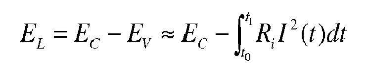
Die Grenzen des Integrals sind wiederum der Startzeitpunkt t0 ab dem der Energieverbraucher in einer Notsituation Energie aus dem Notenergiespeicher entnimmt und der Endzeitpunkt t1 ab dem der Energieverbraucher keine Energie mehr aus dem Notenergiespeicher entnimmt. Die Näherung bei dieser Berechnung besteht darin, dass andere Verluste, als die am Innenwiderstand Ri des Notenergiespeichers anfallenden, vernachlässigt werden.The limits of the integral are in turn the starting time t 0 from the energy consumer in an emergency energy from the Notenergiespeicher takes and the end time t 1 from the energy consumer no longer takes energy from the Notenergiespeicher. The approximation in this calculation is that losses other than those incurred at the internal resistance R i of the note energy storage are neglected.
Zur Bestimmung der entnehmbaren Energie EL sind somit lediglich die im Notenergiespeicher gespeicherte Energie, der Innenwiderstand Ri und der angenommenen Laststromverlauf I(t) notwendig. Die Bestimmung der entnehmbaren Energie EL des Notenergiespeichers und des Innenwiderstandes Ri des Notenergiespeichers kann auf unterschiedliche Art erfolgen. Eine Methode ist das kurzzeitige Entladen des Notenergiespeichers über einen Widerstand und die Messung der Spannung und des Entladestroms. Hieraus wiederum können die dem Notenergiespeicher entnehmbare Energie EL und der Innenwiderstandes Ri des Notenergiespeichers berechnet werden. Der Laststromverlauf I(t) ist abhängig von der Belastung des Energieverbrauchers während der Notsituation und kann insbesondere experimentell bestimmt werden.To determine the removable energy E L are thus only the energy stored in the note energy storage, the internal resistance R i and the assumed load current I (t) necessary. The determination of the removable energy E L of the Notenergiespeichers and the internal resistance R i of the Notenergiespeichers can be done in different ways. One method is the temporary discharge of the note energy storage via a resistor and the measurement of the voltage and the discharge current. From this, in turn, the energy E L removable from the note energy store and the internal resistance R i of the note energy store can be calculated. The load current profile I (t) is dependent on the load of the energy consumer during the emergency situation and in particular can be determined experimentally.
Die dem Notenergiespeicher entnehmbare Leistung ist eine Funktion des Innenwiderstands Ri . Die entnehmbare Leistung ist am größten, wenn der Lastwiderstand RL dem Innenwiderstand Ri entspricht. Hierdurch ist die dem Notenergiespeicher entnehmbare Spitzenleistung Pmax definiert. Die entnehmbare Spitzenleistung Pmax ist proportional zum Kehrwert des Innenwiderstands Ri : 
Insbesondere Windenergieanlagen und die in ihnen verwendeten Notenergiespeicher können extremen Temperaturen ausgesetzt sein. An besonders kalten Standorten führt dies zum Beispiel zur Eisbildung auf den Rotorblättern, wodurch zum einen die Aerodynamik der Rotorblätter nachteilig beeinflusst wird und zum anderen die Gefahr besteht, dass Eis von den Rotorblättern herabstürzt und zu Schäden an Einrichtungen oder sogar Personen in der Umgebung führt. Auch innerhalb von Windenergieanlagen führen besonders niedrige Temperaturen zu Problemen. Beispiele hierfür sind die Bildung von Reif oder Tauwasser, welches bei elektrischen Einrichtungen naturgemäß problematisch ist. Die elektrischen Einrichtungen können durch niedrige Temperaturen aber nicht nur indirekt, wie zum Beispiel über Tauwasser, sondern auch direkt beeinträchtigt werden. So kann insbesondere die bei leistungselektronischen Bauteilen übliche Erwärmung zu starken Temperaturdifferenzen innerhalb der elektronischen Einrichtungen führen, wodurch mechanische Spannungen verursacht werden, die beispielsweise Lötstellen schädigen können.In particular, wind turbines and the note energy storage used in them can be exposed to extreme temperatures. In particularly cold locations, for example, this leads to the formation of ice on the rotor blades, which on the one hand adversely affects the aerodynamics of the rotor blades and, on the other hand, the risk that ice falls from the rotor blades and leads to damage to equipment or even people in the area. Even within wind turbines, particularly low temperatures lead to problems. Examples include the formation of frost or condensation, which is naturally problematic in electrical equipment. The electrical equipment may be affected by low temperatures, but not only indirectly, such as through condensation, but also directly. Thus, in particular, the usual in power electronic components heating lead to strong temperature differences within the electronic devices, causing mechanical stresses that can damage solder joints, for example.
Auch die Energiespeicherelemente in den Notenergiespeichern werden durch niedrige Temperaturen wesentlich beeinflusst. Die meisten heutzutage verwendeten Energiespeicherelemente zeigen eine starke Erhöhung des Innenwiderstands Ri mit abnehmender Temperatur. Da ein höherer Innenwiderstand Ri höhere Verluste EV bedeutet, ist somit die einem Notenergiespeicher bei einer niedrigen Temperatur entnehmbare Energie EL deutlich kleiner als die bei einer höheren Temperatur entnehmbare Energie EL. The energy storage elements in the Notenergiespeichern are significantly influenced by low temperatures. Most of the energy storage elements used today show a large increase in the internal resistance R i with decreasing temperature. Since a higher internal resistance R i is higher losses E V, thus the one emergency energy at a low temperature removable energy E L is significantly smaller than the removable at a higher temperature energy E L.
Das Gleiche gilt für die dem Notenergiespeicher entnehmbare Spitzenleistung Pmax. The same applies to the peak power P max which can be taken from the note energy store .
Um eine ausreichende den Notenergiespeichern entnehmbare Energie EL zu gewährleisten, wird im Stand der Technik die Luft der Schaltschränke, in denen sich die Notenergiespeicher befinden, durch Heizlüfter erwärmt, bevor eine kalte Windenergieanlage in Betrieb geht. Sobald die Luft eine voreingestellte Temperatur, zum Beispiel 5 °C, erreicht hat, wird über einen Thermoschalter ein Signal ausgegeben, der die Betriebsbereitschaft des Notenergiespeichers signalisiert. Dieser Aufwärmprozess ist relativ zeitaufwändig und verzögert somit die Inbetriebnahme einer Windenergieanlage erheblich. Ferner besteht einige Unsicherheit über die tatsächlich entnehmbare Energie EL, da die Lufttemperatur nicht unbedingt eine zuverlässige Aussage über die Temperatur, insbesondere die Kerntemperatur, der Energiespeicherelemente zulässt. Daher wird häufig mit Sicherheitsaufschlägen gearbeitet. Zum Beispiel wird das Signal, das die Betriebsbereitschaft signalisiert erst bei einer Lufttemperatur im Schaltschrank von 10 °C statt bei 5 °C ausgegeben. Hierdurch verzögert sich die Inbetriebnahme der Windenergieanalage weiter, was Verluste für den Betreiber der Windenergieanlage durch deren längeren Stillstand bedeutet. Gravierendere Auswirkungen wären zu befürchten, wenn die entnehmbare Energie EL anhand der Lufttemperatur zu hoch eingeschätzt würde und die Windenergieanlage in Betrieb genommen werden würde, obwohl die entnehmbare Energie EL nicht für eine Notfahrt der Rotorblätter in die Fahnenstellung ausreichte. Fiele in diesem Fall das Netz aus, blieben während einer Notfahrt die Rotorblätter zumindest teilweise im Wind stehen, wodurch bei aufkommenden starken Wind die Windenergieanlage in eine Überdrehzahl ginge und zerstört werden könnte.In order to ensure sufficient energy E L removable from the emergency energy storage devices, in the prior art the air in the control cabinets in which the emergency energy storage devices are located is heated by heating fans before a cold wind energy installation is put into operation. As soon as the air has reached a preset temperature, for example 5 ° C, a signal is issued via a thermal switch which signals the readiness of the note energy storage. This warm-up process is relatively time-consuming and thus significantly delays the commissioning of a wind turbine. Furthermore, there is some uncertainty about the actually removable energy E L , since the air temperature does not necessarily allow a reliable statement about the temperature, in particular the core temperature, of the energy storage elements. Therefore, security surcharges are often used. For example, the signal indicating the readiness for operation is output only at an air temperature in the control cabinet of 10 ° C instead of 5 ° C. This further delays the commissioning of the wind power plant, which means losses for the operator of the wind turbine due to their longer downtime. More serious effects would be feared if the extractable energy E L would be overestimated on the basis of the air temperature and the wind turbine would be put into operation, although the removable energy E L was not sufficient for an emergency drive of the rotor blades in the flag position. In this case, if the grid failed, the rotor blades remained at least partially in the wind during an emergency drive, which would cause the wind turbine to overspeed when the wind was strong and could be destroyed.
Damit ist es die Aufgabe der Erfindung, ein Verfahren zur Betriebsvorbereitung eines Notenergiespeichers, ein Verfahren zur Betriebsvorbereitung eines Pitchsystems für eine Windenergieanlage und ein Computerprogrammprodukt anzugeben, die auch bei niedriger Ausgangstemperatur des Notenergiespeichers anwendbar sind, sowie ein Pitchsystem und eine Windenergieanlage anzugeben, die auch bei niedriger Ausgangstemperatur schnell und sicher betriebsbereit sind.Thus, it is the object of the invention to provide a method for preparing a Notenergiespeichers operation, a method for preparing a pitch system for a wind turbine and a computer program product that are applicable even at low output temperature of the Notenergiespeichers, and to provide a pitch system and a wind turbine, which also in low outlet temperature are quickly and safely operational.
Die zuvor hergeleitete und aufgezeigte Aufgabe ist ausgehend von dem eingangs beschriebenen Verfahren zur Betriebsvorbereitung eines Notenergiespeichers dadurch gelöst, dass der Notenergiespeicher über eine Entladeeinrichtung zum Erwärmen des Notenergiespeichers entladen wird und die dem Notenergiespeicher entnehmbare Energie EL und/oder die dem Notenergiespeicher entnehmbare Spitzenleistung Pmax erneut bestimmt wird.The previously derived and indicated object is achieved on the basis of the method described above for preparing a Notenergiespeichers that the Notenergiespeicher is discharged via an unloading device for heating the Notenergiespeichers and the Notenergiespeicher removable energy E L and / or the Notenergiespeicher removable peak power P max is determined again.
Die Erfindung macht sich den Nachteil des steigenden Innenwiderstandes Ri bei niedrigen Temperaturen zu Nutze, um durch ein Entladen des Notenergiespeichers den Notenergiespeicher zu erwärmen. Durch die Erwärmung des Notenergiespeichers verringert sich der Innenwiderstand Ri . Da der Innenwiderstand Ri für einen wesentlichen Teil der Verluste EV verantwortlich ist, verringern sich diese ebenfalls. Entsprechend nimmt die dem Notenergiespeicher entnehmbare Spitzenleistung Pmax durch die Verringerung des Innenwiderstands Ri zu.The invention makes use of the disadvantage of increasing internal resistance R i at low temperatures in order to heat the note energy store by discharging the note energy store. By heating the Notenergiespeichers reduces the internal resistance R i . Since the internal resistance R i is responsible for a substantial part of the losses E V , these are also reduced. Accordingly, the peak power P max , which can be taken from the note energy store, increases by reducing the internal resistance R i .
Besonders bevorzugt wird während des Entladens die dem Notenergiespeicher entnehmbare Energie EL und/oder die dem Notenergiespeicher entnehmbare Spitzenleistung Pmax kontinuierlich bestimmt. Hierdurch wird sichergestellt, dass der Notenergiespeicher nur soweit wie nötig entladen wird. Alternativ kann das Entladen des Notenergiespeichers für einen vorbestimmten Zeitraum erfolgen, oder bis eine vorbestimmte Energiemenge dem Notenergiespeicher entnommen worden ist.Particularly preferably, during the discharge, the energy E L which can be taken from the note energy store and / or the peak power P max which can be taken from the note energy store are continuously determined. This ensures that the note energy storage is only discharged as far as necessary. Alternatively, the discharge of the Notenergiespeichers for a predetermined period of time, or until a predetermined amount of energy has been removed from the Notenergiespeicher.
Vorzugsweise wird der Notenergiespeicher über die Entladeeinrichtung mit einem Lastwiderstand RL belastet, der kleiner als der Innenwiderstand Ri ist, insbesondere höchstens halb so groß wie der Innenwiderstand Ri ist, besonders bevorzugt höchstens zehn Prozent des Innenwiderstands Ri beträgt. Auf diese Weise wird der Großteil der dem Notenergiespeicher beim Entladen entnommenen Energie am Innenwiderstand Ri in Wärme umgewandelt.Preferably, the note energy storage is loaded via the discharge device with a load resistance R L , which is smaller than the internal resistance R i , in particular at most half as large as the internal resistance R i , more preferably at most ten percent of the internal resistance R i . In this way, the majority of energy removed from the note energy store during discharge is converted into heat at the internal resistance R i .
Gemäß einer vorteilhaften Weiterbildung der Erfindung ist vorgesehen, dass der Notenergiespeicher geladen wird, wenn die erneute Bestimmung zum Ergebnis hatte, dass die dem Notenergiespeicher entnehmbare Energie EL einen festlegbaren Mindestenergiewert nicht erreicht hat und/oder die dem Notenergiespeicher entnehmbare Spitzenleistung Pmax einen festlegbaren Mindestleistungswert nicht erreicht hat und die dem Notenergiespeicher entnehmbare Energie EL und/oder die dem Notenergiespeicher entnehmbare Spitzenleistung Pmax erneut bestimmt wird. Für den Fall, dass durch das Entladen des Notenergiespeichers alleine nicht die notwendige Mindestenergie und/oder nicht die notwendige Mindestleistung erreicht werden, kann durch einfaches Laden des Notenergiespeichers dieses Ziel bzw. diese Ziele dennoch erreicht werden. Der Notenergiespeicher kann zum Beispiel für einen vorbestimmten Zeitraum, mit einer vorbestimmten Energiemenge oder bis zu einem vorbestimmten Level geladen werden, wobei das Level insbesondere mindestens 80 %, vorzugsweise mindestens 90 % und besonders bevorzugt mindestens 95 % der maximal im Notenergiespeicher speicherbaren Energiemenge beträgt.According to an advantageous embodiment of the invention, it is provided that the note energy storage is loaded when the re-determination had the result that the power E L removable energy has not reached a definable minimum energy value and / or the Music power removable peak power P max has not reached a definable minimum power level and the energy E L removable from the Notenergiespeicher and / or the Notenergie memory removable peak power P max is determined again. In the event that by discharging the Notenergiespeichers alone not the necessary minimum energy and / or not the necessary minimum performance can be achieved by simply loading the Notenergiespeichers this goal or these goals can still be achieved. The note energy store may be loaded, for example, for a predetermined period of time, with a predetermined amount of energy or up to a predetermined level, the level being at least 80%, preferably at least 90%, and most preferably at least 95% of the maximum amount of energy that can be stored in the note energy store.
Eine vorteilhafte Ausgestaltung der Erfindung zeichnet sich dadurch aus, dass vor dem Entladen des Notenergiespeichers der Notenergiespeicher geladen wird. Sofern der Notenergiespeicher zu Beginn des erfindungsgemäßen Verfahrens nur eine sehr geringe Energiemenge enthält oder sogar vollständig entladen ist, ist es vorteilhaft, den Notenergiespeicher zunächst zu Laden, um das darauffolgende Entladen des Notenergiespeichers zu ermöglichen. Zum Laden des Notenergiespeichers ist vorzugsweise eine Ladeeinrichtung vorgesehen. Die Ladeeinrichtung kann zum Beispiel durch einen Gleichrichter gebildet werden, der den Wechselstrom eines Versorgungsnetzes in einen Gleichstrom gleichrichtet. Insbesondere kann die Ladeeinrichtung auch durch den Energieverbraucher selbst gebildet werden, wenn dieser beispielsweise einen Motor aufweist, der auch als Generator betreibbar ist und durch den Energie in den Notenergiespeicher speisbar ist.An advantageous embodiment of the invention is characterized in that the note energy storage is loaded before unloading the Notenergiespeichers. If the note energy storage at the beginning of the method according to the invention contains only a very small amount of energy or even completely discharged, it is advantageous to first load the note energy storage to allow the subsequent discharge of the note energy storage. For loading the Notenergiespeichers preferably a charging device is provided. The charging device can be formed, for example, by a rectifier, which rectifies the alternating current of a supply network into a direct current. In particular, the charging device can also be formed by the energy consumer himself, if this has, for example, a motor which can also be operated as a generator and can be fed by the energy into the emergency energy storage.
Gemäß einer besonders vorteilhaften Weiterbildung der Erfindung ist vorgesehen, dass das Laden des Notenergiespeichers höchstens mit dem maximal zulässigen Ladestrom des Notenergiespeichers erfolgt. Durch diese Strombegrenzung wird der Notenergiespeicher vor Überlastungen geschützt und die Lebensdauer des Notenergiespeichers erhöht.According to a particularly advantageous embodiment of the invention it is provided that the loading of the Notenergiespeichers at most with the maximum allowable charging current of the Notenergiespeichers. This current limit protects the note energy storage against overloads and increases the life of the note energy storage.
Bei einer bevorzugten Ausgestaltung der Erfindung ist vorgesehen, dass die Entladeeinrichtung den einen Energieverbraucher oder wenigstens einen der Energieverbraucher umfasst. Somit kann der eine Energieverbraucher oder wenigstens einer der Energieverbraucher als Lastwiderstand fungieren über den der Notenergiespeicher entladen werden kann. Hierdurch kann auf einen separaten Lastwiderstand, der lediglich dem Entladen des Notenergiespeichers dient, verzichtet werden. Wenn der Energieverbraucher beispielsweise ein Elektromotor eines Pitchsystems ist, kann bei dem Entladen des Notenergiespeichers über den Elektromotor nicht nur der Notenergiespeicher erwärmt werden, sondern gleichzeitig auch der Elektromotor erwärmt und somit auf den bevorstehenden Betrieb vorbereitet werden. Ist ferner ein Bremswiderstand, auch Bremschopper genannt, vorhanden, der der Dissipation überschüssiger Energie dient, kann auch dieser Bremswiderstand als Lastwiderstand fungieren.In a preferred embodiment of the invention it is provided that the unloading the one energy consumers or at least one of Energy consumer includes. Thus, the one energy consumer or at least one of the energy consumers can act as a load resistor via which the emergency energy storage can be discharged. This makes it possible to dispense with a separate load resistor, which merely serves to discharge the note energy store. If the energy consumer, for example, an electric motor of a pitch system, not only the Notenergiespeicher can be heated when unloading the Notenergiespeichers on the electric motor, but also heated the electric motor and thus be prepared for the upcoming operation. Furthermore, if a braking resistor, also called a brake chopper, is present, which serves to dissipate excess energy, this braking resistor can also function as a load resistor.
Bei einer weiteren bevorzugten Ausgestaltung der Erfindung ist vorgesehen, dass die Entladeeinrichtung wenigstens einen Heizwiderstand aufweist, deren Abwärme wiederum zum direkten oder indirekten Heizen des Notenergiespeichers verwendet wird. Der Heizwiderstand kann beispielsweise in unmittelbare Nähe des Notenergiespeichers angeordnet sein, im direkten Kontakt mit dem Notenergiespeicher stehen oder gleichzeitig als Heizwiderstand eines Heizlüfters fungieren. Hierdurch wird nicht nur die beim Entladen des Notenergiespeichers am Innenwiderstand anfallende Wärme zum Erwärmen des Notenergiespeichers genutzt, sondern auch die in der Entladeeinrichtung in Wärme umgewandelte elektrische Leistung.In a further preferred embodiment of the invention it is provided that the discharge device has at least one heating resistor whose waste heat is in turn used for direct or indirect heating of the Notenergiespeichers. The heating resistor can be arranged, for example, in the immediate vicinity of the Notenergiespeichers, are in direct contact with the Notenergiespeicher or simultaneously act as a heating resistor of a fan heater. As a result, not only the heat accumulating on the internal resistance when discharging the note energy storage is used to heat the note energy storage, but also the electric power converted into heat in the discharge device.
Gemäß einer weiteren bevorzugten Ausgestaltung der Erfindung ist vorgesehen, dass die Energiespeicherelemente Kondensatoren, insbesondere Ultrakondensatoren aufweisen. Die Notenergiespeicher können sowohl eine einzelne Kondensatorzelle als auch eine Parallelschaltung und/oder Reihenschaltung von mehreren Kondensatorzellen aufweisen. Die Kapazität C des Notenergiespeichers bezeichnet bei mehreren miteinander verschalteten Kondensatorzellen somit die resultierende Gesamtkapazität C der miteinander verschalteten Kondensatorzellen.According to a further preferred embodiment of the invention, it is provided that the energy storage elements have capacitors, in particular ultracapacitors. The Notenergiespeicher may have both a single capacitor cell and a parallel connection and / or series connection of a plurality of capacitor cells. The capacitance C of the Notenergiespeichers thus designated at several interconnected capacitor cells, the resulting total capacitance C of the interconnected capacitor cells.
Der Begriff Ultrakondensatoren umfasst elektrochemische Kondensatoren, die sowohl eine Doppelschichtkapazität als auch eine Pseudokapazität aufweisen. Teilweise wird auch der Begriff Superkondensatoren verwendet. Je nachdem welche der beiden Kapazitäten überwiegt, werden die Ultrakondensatoren in eine von drei Familien eingeordnet. Als Doppelschichtkondensatoren oder EDLC (electric double-layer capacitor) werden Ultrakondensatoren bezeichnet, bei denen die Doppelschichtkapazität überwiegt. Als Pseudokondensatoren werden Ultrakondensatoren bezeichnet, bei denen die Pseudokapazität überwiegt. Als Hybridkondensatoren werden Ultrakondensatoren bezeichnet, bei denen die Doppelschichtkapazität und die Pseudokapazität in etwa gleichem Maße zur Gesamtkapazität C des Ultrakondensators beitragen. Der Einfluss der Temperatur auf den Innenwiderstand Ri ist bei Kondensatoren besonders deutlich und ist zumeist am stärksten bei Temperaturen von unter 0 °C.The term ultracapacitors includes electrochemical capacitors having both a double-layer capacitance and a pseudo-capacitance. In part, the term supercapacitors is also used. Depending on which of the two capacities is predominant, the ultracapacitors are classified in one of three families. As double-layer capacitors or EDLC (electric double-layer capacitor) Ultra capacitors are referred to, in which the double-layer capacitance outweighs. Pseudo-capacitors are ultra-capacitors in which the pseudo-capacitance predominates. Hybrid capacitors are ultra-capacitors in which the double-layer capacitance and the pseudo-capacitance contribute to approximately the same extent to the total capacitance C of the ultracapacitor. The influence of temperature on the internal resistance R i is particularly pronounced in capacitors and is mostly strongest at temperatures below 0 ° C.
Die Bestimmung der Kapazität C des Notenergiespeichers kann ebenso wie die Bestimmung des Innenwiderstandes Ri des Notenergiespeichers durch das kurzzeitige Entladen des Notenergiespeichers über einen Widerstand und die Messung der Spannung und des Entladestroms erfolgen.The determination of the capacity C of the Notenergiespeichers can be done as well as the determination of the internal resistance R i of the Notenergiespeichers by briefly discharging the Notenergiespeichers via a resistor and the measurement of the voltage and the discharge current.
Die in dem Notenergiespeicher gespeicherte Energie EC ergibt sich somit zu: 
Die in diese Berechnung einfließende Ladespannung UL ist ebenfalls durch einfachste Messungen bestimmbar. Die entnehmbare Energie EL lässt sich demnach gemäß der eingangs beschriebenen Näherung wie folgt berechnen: 
Darüber hinaus ist es vorteilhaft, wenn der Entladestrom auf einen Höchstwert begrenzt wird, wobei insbesondere der Höchstwert ein Wert kleiner oder gleich der maximal zulässigen Verlustleistung der Entladeeinrichtung gewählt ist. Auf diese Weise wird die Entladeeinrichtung vor Überlastungen geschützt.Moreover, it is advantageous if the discharge current is limited to a maximum value, wherein in particular the maximum value is chosen to be less than or equal to the maximum permissible power loss of the unloading device. In this way, the unloader is protected from overloads.
Gemäß einer weiteren bevorzugten Weiterbildung der Erfindung ist vorgesehen, dass die Begrenzung des Entladestroms durch eine Pulsweitenmodulation erfolgt, wobei insbesondere der Spitzenentladestrom auf den maximal zulässigen Pulsstrom des Stromkreises umfassend den Notenergiespeicher und die Entladeeinrichtung beschränkt wird. Der Entladestrom ist hierbei die über mehrere Pulse gemittelte resultierende Stromstärke. Der Spitzenentladestrom bezeichnet die maximale Stromstärke, den ein einzelner Puls der Pulsweitenmodulation erreicht.According to a further preferred embodiment of the invention, it is provided that the limitation of the discharge current is effected by a pulse width modulation, wherein in particular the peak discharge current to the maximum allowable pulse current of the circuit comprising the Notenergiespeicher and the unloading device is limited. The discharge current in this case is the average over several pulses resulting current. Peak discharge current is the maximum current that a single pulse width modulation pulse reaches.
Bei einer vorteilhaften Ausgestaltung der Erfindung ist vorgesehen, dass wenigstens eine physikalischen Größe, die eine Aussage über die Kerntemperatur des einen Energiespeicherelements oder der mehreren Energiespeicherelemente des Notenergiespeichers zulässt, gemessen wird, die Kerntemperatur auf Grundlage der physikalischen Größe oder der physikalischen Größen berechnet wird und das Entladen des Notenergiespeichers mindestens solange erfolgt, bis die Kerntemperatur einen festlegbaren Temperaturschwellwert erreicht hat. Dies bietet gegenüber der aus dem Stand der Technik bekannten Methode die Lufttemperatur zu bestimmen, eine deutlich aussagekräftigere Möglichkeit zur Temperaturbestimmung. Die Betriebsbereitschaft gilt hierbei erst dann als festgestellt, wenn der Temperaturschwellwert erreicht wird. D. h. die Inbetriebnahme des Notenergiespeichers kann erst dann erfolgen.In an advantageous embodiment of the invention, it is provided that at least one physical quantity that allows a statement about the core temperature of the one energy storage element or the plurality of energy storage elements of the Notenergiespeichers is measured, the core temperature is calculated on the basis of physical size or physical quantities and the Unloading the note energy storage is at least until the core temperature has reached a definable temperature threshold. This offers over the known from the prior art method to determine the air temperature, a much more meaningful way to determine the temperature. The readiness for operation is only then considered as determined when the temperature threshold is reached. Ie. commissioning the Notenergiespeichers can take place only then.
Gemäß einer weiteren vorteilhaften Ausgestaltung der Erfindung ist vorgesehen, dass bei der Berechnung der Kerntemperatur Alterungseffekte des Notenergiespeichers, die den Zusammenhang zwischen der physikalischen Größe oder den physikalischen Größen und der Kerntemperatur verändern, berücksichtigt werden. Der Zusammenhang zwischen der physikalischen Größe oder den physikalischen Größen und der Kerntemperatur kann sich mit der Zeit und/oder mit der Anzahl der Lade/Entladezyklen des Notenergiespeichers verändern. Die Art und der Umfang dieser Veränderungen ist häufig bekannt und kann somit bei der Berechnung der Kerntemperatur berücksichtigt werden, wodurch sich die Genauigkeit der Berechnung auch bei gealterten Notenergiespeichern aufrechterhalten lässt.According to a further advantageous embodiment of the invention, it is provided that in the calculation of the core temperature aging effects of the Notenergiespeichers, which change the relationship between the physical quantity or the physical quantities and the core temperature, are taken into account. The relationship between the physical quantity or physical quantities and the core temperature may vary with time and / or with the number of cycles of charge energy storage. The nature and extent of these changes is often known and can thus be taken into account in the calculation of the core temperature, whereby the accuracy of the calculation can be maintained even with aged note energy storage.
Bei einer besonders vorteilhaften Ausgestaltung der Erfindung ist vorgesehen, dass die physikalische Größe oder die physikalischen Größen die Kapazität C des Notenergiespeichers und/oder den Innenwiderstand Ri des Notenergiespeichers umfassen. Wie bereits beschreiben zeigt der Innenwiderstand Ri eine deutliche Temperaturabhängigkeit, somit kann ausgehend vom Innenwiderstand Ri auf die Temperatur des Notenergiespeichers bzw. der Energiespeicherelemente geschlossen werden. Darüber hinaus ist auch die Kapazität C temperaturabhängig und kann auf analoge Weise zur Bestimmung der Temperatur des Notenergiespeichers bzw. der Energiespeicherelemente herangezogen werden.In a particularly advantageous embodiment of the invention, it is provided that the physical variable or the physical variables include the capacity C of the note energy store and / or the internal resistance R i of the note energy store. As already described, the internal resistance R i shows a clear temperature dependence, thus can starting from the internal resistance R i to the temperature of the note energy storage or the energy storage elements are closed. In addition, the capacitance C is temperature-dependent and can be used in an analogous manner for determining the temperature of the Notenergiespeichers or the energy storage elements.
Die zuvor hergeleitete und aufgezeigte Aufgabe ist ausgehend von dem eingangs beschriebenen Verfahren zur Betriebsvorbereitung eines Pitchsystems für eine Windenergieanlage dadurch gelöst, dass eines der zuvor beschriebenen Verfahren auf den einen Notenergiespeicher oder wenigstens einen der Notenergiespeicher des Pitchsystems angewendet wird. Die zuvor hergeleitete und aufgezeigte Aufgabe ist ausgehend von dem eingangs beschriebenen Pitchsystem dadurch gelöst, dass das Pitchsystem zur Ausführung des vorgenannten Verfahrens ausgestaltet ist. Die zuvor hergeleitete und aufgezeigte Aufgabe ist ausgehend von der eingangs beschriebenen Windenergieanlage dadurch gelöst, dass die Windenergieanlage ein derartiges Pitchsystem umfasst.The previously derived and indicated object is achieved on the basis of the method for operating preparation of a pitch system for a wind energy plant described above in that one of the methods described above is applied to the one note energy store or at least one of the note energy memories of the pitch system. The previously derived and indicated object is achieved on the basis of the pitch system described above in that the pitch system is designed to carry out the aforementioned method. The previously derived and indicated object is achieved on the basis of the wind energy installation described above in that the wind energy installation comprises such a pitch system.
Die Ausführung der einzelnen Verfahrensschritte der erfindungsgemäßen Verfahren kann zum Beispiel durch ein Computerprogramm erfolgen, welches auf einem Speichermedium, wie zum Beispiel einem Halbleiterspeicher, einem magnetischen Speicher oder einem optischen Speicher, gespeichert ist und durch eine Steuerungseinrichtung verarbeitet wird.The execution of the individual method steps of the method according to the invention can be carried out for example by a computer program, which is stored on a storage medium, such as a semiconductor memory, a magnetic memory or an optical memory, and is processed by a control device.
Im Einzelnen gibt es nun eine Vielzahl von Möglichkeiten, das erfindungsgemäße Verfahren zur Betriebsvorbereitung eines Notenergiespeichers auszugestalten und weiterzubilden. Dazu wird auf die dem Patentanspruch 1 nachgeordneten Patentansprüche sowie auf die nachfolgende detaillierte Beschreibung bevorzugter Ausführungsbeispiele der Erfindung unter Bezugnahme auf die Zeichnung verwiesen.In particular, there are now a variety of ways to design and develop the inventive method for preparing a Notenergiespeichers operation. For this purpose, reference is made to the claims subordinate to claim 1 and to the following detailed description of preferred embodiments of the invention with reference to the drawings.
In der Zeichnung zeigt
-
Fig. 1 schematisch den Zusammenhang zwischen der Temperatur T eines Energiespeicherelements und seinem Innenwiderstand Ri , -
Fig. 2 ein Ablaufdiagram einer bevorzugten Ausgestaltung des erfindungsgemäßen Verfahrens und -
Fig. 3 schematisch einen Teil eines erfindungsgemäßen Pitchsystems.
-
Fig. 1 schematically the relationship between the temperature T of an energy storage element and its internal resistance R i , -
Fig. 2 a flow chart of a preferred embodiment of the method according to the invention and -
Fig. 3 schematically a part of a pitch system according to the invention.
Wenn die Bestimmung (B) zum Ergebnis hatte, dass die dem Notenergiespeicher entnehmbare Energie EL einen festlegbaren Mindestenergiewert nicht erreicht hat und/oder die dem Notenergiespeicher entnehmbare Spitzenleistung Pmax einen festlegbaren Mindestleistungswert nicht erreicht hat, dann wird zunächst der Notenergiespeicher über eine Entladeeinrichtung zum Erwärmen des Notenergiespeichers entladen (E). Hierauf wird die dem Notenergiespeicher entnehmbare Energie EL und/oder die dem Notenergiespeicher entnehmbare Spitzenleistung Pmax erneut bestimmt (B). Die erneute Bestimmung (B) kann auch kontinuierlich während des Entladens (E) erfolgen, so dass das die beiden Verfahrensschritte im Wesentlichen parallel ablaufen. Wenn die erneute Bestimmung (B) zum Ergebnis hat, dass die dem Notenergiespeicher entnehmbare Energie EL einen festlegbaren Mindestenergiewert erreicht hat und/oder die dem Notenergiespeicher entnehmbare Spitzenleistung Pmax einen festlegbaren Mindestleistungswert erreicht hat, dann wird die Betriebsbereitschaft festgestellt (X) und insbesondere ein Signal an eine übergeordnete Steuerungseinrichtung ausgegeben, wobei das Signal die Betriebsbereitschaft signalisiert.If the determination (B) had the result that the energy E L removable from the note energy store has not reached a definable minimum energy value and / or that the note energy store removable peak power P max has not reached a definable minimum power value, then the Notenergiespeicher is initially discharged via an unloading device for heating the Notenergiespeichers (E). The energy E L which can be taken from the energy store and / or the peak power P max which can be taken from the energy store are then redetermined (B). The re-determination (B) can also be carried out continuously during the discharge (E), so that the two process steps are substantially parallel. If the re-determination (B) has the result that the energy E L removable from the energy store has reached a definable minimum energy value and / or the peak power P max which can be taken from the energy store has reached a definable minimum power value, the readiness for operation is determined (X) and in particular a signal is output to a higher-level control device, wherein the signal signals the operational readiness.
Wenn die erneute Bestimmung (B) zum Ergebnis hatte, dass die dem Notenergiespeicher entnehmbare Energie EL einen festlegbaren Mindestenergiewert nicht erreicht hat und/oder die dem Notenergiespeicher entnehmbare Spitzenleistung Pmax einen festlegbaren Mindestleistungswert nicht erreicht hat, wird der Notenergiespeicher geladen (L). Das Laden (L) kann zum Beispiel solange erfolgen bis der Notenergiespeicher zu 90 % geladen ist. Danach wird die dem Notenergiespeicher entnehmbare Energie EL und/oder die dem Notenergiespeicher entnehmbare Spitzenleistung Pmax erneut bestimmt (B).If the re-determination (B) had the result that the energy E L which can be taken from the energy store has not reached a definable minimum energy value and / or the peak power P max which can be taken from the energy store has not reached a definable minimum power value, the music grade memory is loaded (L). Loading (L) can be done, for example, until the note energy storage is 90% charged. Thereafter, the energy E L removable from the note energy store and / or the peak power P max which can be taken from the note energy store are redetermined (B).
Die durch die Schritte L, B, E und B gebildete Schleife wird solange durchlaufen, bis eine der Bestimmungen (B) zum Ergebnis hat, dass die dem Notenergiespeicher entnehmbare Energie EL einen festlegbaren Mindestenergiewert erreicht hat und/oder die dem Notenergiespeicher entnehmbare Spitzenleistung Pmax einen festlegbaren Mindestleistungswert erreicht hat. Alternativ kann die Schleife nach einer vorgegebenen maximalen Anzahl von Durchgängen unterbrochen und ein Fehlersignal an eine Steuerungseinrichtung ausgegeben werden.The loop formed by steps L, B, E and B is run through until one of the determinations (B) has the result that the energy E L removable from the note energy store has reached a definable minimum energy value and / or the peak power P can be taken from the note energy store max has reached a definable minimum power value. Alternatively, the loop may be interrupted after a predetermined maximum number of passes and an error signal output to a controller.
Wird das erfindungsgemäße Verfahren zum Beispiel in einem Anwendungsbereich angewendet, in dem lediglich die dem Notenergiespeicher entnehmbare Energie EL relevant ist und die dem Notenergiespeicher entnehmbare Spitzenleistung Pmax keine Rolle spielt, wird bei der Bestimmung (B) auch nur die dem Notenergiespeicher entnehmbare Energie EL bestimmt (B) und die Betriebsbereitschaft festgestellt (X), sobald die dem Notenergiespeicher entnehmbare Energie EL den festgelegten Mindestenergiewert erreicht hat.If the method according to the invention is used, for example, in an application in which only the energy E L removable from the energy store is relevant and the peak power P max which can be taken from the energy store does not play any role in determination (B), only the energy E which can be taken from the energy store L determines (B) and the operational readiness determined (X) as soon as the energy E L removable from the note energy store has reached the specified minimum energy value.
In
- 11
- Notenergiespeicheremergency energy
- 22
- EnergiespeicherelementEnergy storage element
- 33
- Energieverbraucherenergy consumers
- 44
- Entladeeinrichtungunloading
- 55
- Ladeeinrichtungloader
- 66
- Steuerungseinrichtungcontrol device
Claims (15)
dadurch gekennzeichnet,
dass der Notenergiespeicher (1) über eine Entladeeinrichtung (4) zum Erwärmen des Notenergiespeichers (1) entladen wird und die dem Notenergiespeicher (1) entnehmbare Energie EL und/oder die dem Notenergiespeicher (1) entnehmbare Spitzenleistung Pmax erneut bestimmt wird.Method for the operational preparation of a Notenergiespeichers (1) with at least one energy storage element (2), wherein the Notenergiespeicher (1) is designed to provide electrical grade energy for at least one energy consumer (3), wherein the Notenergiespeicher (1) removable energy E L and / or the emergency energy (1) removable peak power P max is determined and the operational readiness is established as soon as the the emergency energy (1) removable energy e L has reached a definable minimum energy value and / or the emergency energy (1) removable peak power P max a definable Has reached minimum performance value,
characterized,
in that the note energy store (1) is discharged via an unloading device (4) for heating the note energy store (1) and the energy E L removable from the note energy store (1) and / or the peak power P max removable from the note energy store (1) is again determined.
dadurch gekennzeichnet,
dass ein Verfahren nach einem der Patentansprüche 1 bis 11 auf den einen Notenergiespeicher (1) oder wenigstens einen der Notenergiespeicher (1) des Pitchsystems angewendet wird.Method for the operational preparation of a pitch system for a wind power plant, wherein the pitch system has at least one note energy store (1) with at least one energy storage element (2),
characterized,
in that a method according to one of the claims 1 to 11 is applied to the one note energy store (1) or at least one of the note energy stores (1) of the pitch system.
dadurch gekennzeichnet,
dass das Pitchsystem zur Ausführung des Verfahrens nach Anspruch 12 ausgestaltet ist.Pitch system for a wind energy plant, wherein the pitch system has at least one note energy storage (1) with at least one energy storage element (2),
characterized,
in that the pitch system is designed to carry out the method according to claim 12.
Priority Applications (11)
| Application Number | Priority Date | Filing Date | Title |
|---|---|---|---|
| EP14184278.1A EP2996219A1 (en) | 2014-09-10 | 2014-09-10 | Method to prepare a back up energy store for operation |
| KR1020177009692A KR20170057319A (en) | 2014-09-10 | 2015-08-21 | Method for preparing an emergency energy store for operation |
| JP2017512919A JP2017529042A (en) | 2014-09-10 | 2015-08-21 | Method of preparing an emergency energy storage device for operation |
| EP15757195.1A EP3192145B1 (en) | 2014-09-10 | 2015-08-21 | Method to prepare a back up energy store for operation |
| DK15757195.1T DK3192145T3 (en) | 2014-09-10 | 2015-08-21 | PROCEDURE FOR PREPARING A BACKUP ENERGY STORAGE FOR OPERATION |
| ES15757195T ES2873361T3 (en) | 2014-09-10 | 2015-08-21 | Procedure for the operational preparation of an emergency energy accumulator |
| CN201580049674.3A CN107078540B (en) | 2014-09-10 | 2015-08-21 | Method for preparing an emergency energy storage device for operation |
| CA2960737A CA2960737C (en) | 2014-09-10 | 2015-08-21 | Process for preparing an emergency energy store for operation |
| PCT/EP2015/069287 WO2016037834A1 (en) | 2014-09-10 | 2015-08-21 | Method for preparing an emergency energy store for operation |
| US15/510,577 US10985599B2 (en) | 2014-09-10 | 2015-08-21 | Method for preparing an emergency energy store for operation |
| BR112017004755A BR112017004755B8 (en) | 2014-09-10 | 2015-08-21 | pitch system, method of preparing a pitch system and wind turbine system |
Applications Claiming Priority (1)
| Application Number | Priority Date | Filing Date | Title |
|---|---|---|---|
| EP14184278.1A EP2996219A1 (en) | 2014-09-10 | 2014-09-10 | Method to prepare a back up energy store for operation |
Publications (1)
| Publication Number | Publication Date |
|---|---|
| EP2996219A1 true EP2996219A1 (en) | 2016-03-16 |
Family
ID=51540986
Family Applications (2)
| Application Number | Title | Priority Date | Filing Date |
|---|---|---|---|
| EP14184278.1A Withdrawn EP2996219A1 (en) | 2014-09-10 | 2014-09-10 | Method to prepare a back up energy store for operation |
| EP15757195.1A Active EP3192145B1 (en) | 2014-09-10 | 2015-08-21 | Method to prepare a back up energy store for operation |
Family Applications After (1)
| Application Number | Title | Priority Date | Filing Date |
|---|---|---|---|
| EP15757195.1A Active EP3192145B1 (en) | 2014-09-10 | 2015-08-21 | Method to prepare a back up energy store for operation |
Country Status (10)
| Country | Link |
|---|---|
| US (1) | US10985599B2 (en) |
| EP (2) | EP2996219A1 (en) |
| JP (1) | JP2017529042A (en) |
| KR (1) | KR20170057319A (en) |
| CN (1) | CN107078540B (en) |
| BR (1) | BR112017004755B8 (en) |
| CA (1) | CA2960737C (en) |
| DK (1) | DK3192145T3 (en) |
| ES (1) | ES2873361T3 (en) |
| WO (1) | WO2016037834A1 (en) |
Cited By (3)
| Publication number | Priority date | Publication date | Assignee | Title |
|---|---|---|---|---|
| WO2020011321A1 (en) * | 2018-07-10 | 2020-01-16 | Vestas Wind Systems A/S | Wind turbine power consumption control |
| WO2020228919A1 (en) * | 2019-05-16 | 2020-11-19 | Vestas Wind Systems A/S | Controllable power backup system for wind turbine |
| WO2020228918A1 (en) * | 2019-05-16 | 2020-11-19 | Vestas Wind Systems A/S | Full dc voltage power backup system for wind turbine |
Families Citing this family (1)
| Publication number | Priority date | Publication date | Assignee | Title |
|---|---|---|---|---|
| KR102657153B1 (en) * | 2019-09-11 | 2024-04-15 | 한국전력공사 | DC Converting System and Design Method of Chopper-Resister |
Citations (5)
| Publication number | Priority date | Publication date | Assignee | Title |
|---|---|---|---|---|
| CA2448536A1 (en) * | 2001-05-25 | 2002-12-05 | Avestor Limited Partnership | Back-up power system |
| EP2578876A1 (en) * | 2011-10-05 | 2013-04-10 | Siemens Aktiengesellschaft | Pitch system for a wind energy assembly and method for operating the same |
| US20130113441A1 (en) * | 2011-11-04 | 2013-05-09 | Azbil Corporation | Electric actuator |
| DE102013218069A1 (en) * | 2012-09-20 | 2014-03-20 | Shanghai Greatway Top Power Co., Ltd. | A LI BATTERY EMERGENCY POWER SUPPLY WITH AUTOMATIC HEATING AT LOW TEMPERATURE |
| US20140162091A1 (en) * | 2011-08-19 | 2014-06-12 | Ngk Insulators, Ltd. | Method of controlling storage battery, apparatus for controlling storage battery, and electric power control system |
Family Cites Families (11)
| Publication number | Priority date | Publication date | Assignee | Title |
|---|---|---|---|---|
| US5362942A (en) * | 1993-08-24 | 1994-11-08 | Interdigital Technology Corporation | Battery heating system using internal battery resistance |
| US6340879B1 (en) * | 1999-02-03 | 2002-01-22 | Nokia Mobile Phones Ltd. | Device for reactivating an electric battery |
| US7227275B2 (en) * | 2005-02-01 | 2007-06-05 | Vrb Power Systems Inc. | Method for retrofitting wind turbine farms |
| JP4807058B2 (en) * | 2005-11-10 | 2011-11-02 | パナソニック株式会社 | Vehicle power supply |
| JP5208374B2 (en) * | 2006-04-18 | 2013-06-12 | シャープ株式会社 | Grid interconnection power conditioner and grid interconnection power system |
| EP2212194B1 (en) * | 2007-11-01 | 2017-10-18 | Windurance LLC | System and method for controlling a turbine blade |
| US8513829B1 (en) * | 2008-11-06 | 2013-08-20 | P.C. Krause & Associates, Inc. | Electrical accumulator unit for providing auxiliary power to an electrical network |
| EP2463981A4 (en) * | 2009-08-04 | 2017-09-20 | Nec Corporation | Energy system |
| US8766566B2 (en) | 2010-12-20 | 2014-07-01 | Nippon Soken, Inc. | System for causing temperature rise in battery |
| ES2672870T3 (en) * | 2012-03-19 | 2018-06-18 | Awilco Aps | Auxiliary power system for a wind turbine |
| US9442165B2 (en) * | 2012-07-07 | 2016-09-13 | Nec Corporation | Method for estimating battery life in presence of partial charge and discharge cycles |
-
2014
- 2014-09-10 EP EP14184278.1A patent/EP2996219A1/en not_active Withdrawn
-
2015
- 2015-08-21 DK DK15757195.1T patent/DK3192145T3/en active
- 2015-08-21 WO PCT/EP2015/069287 patent/WO2016037834A1/en active Application Filing
- 2015-08-21 CN CN201580049674.3A patent/CN107078540B/en active Active
- 2015-08-21 JP JP2017512919A patent/JP2017529042A/en active Pending
- 2015-08-21 ES ES15757195T patent/ES2873361T3/en active Active
- 2015-08-21 US US15/510,577 patent/US10985599B2/en active Active
- 2015-08-21 EP EP15757195.1A patent/EP3192145B1/en active Active
- 2015-08-21 CA CA2960737A patent/CA2960737C/en active Active
- 2015-08-21 KR KR1020177009692A patent/KR20170057319A/en unknown
- 2015-08-21 BR BR112017004755A patent/BR112017004755B8/en active IP Right Grant
Patent Citations (5)
| Publication number | Priority date | Publication date | Assignee | Title |
|---|---|---|---|---|
| CA2448536A1 (en) * | 2001-05-25 | 2002-12-05 | Avestor Limited Partnership | Back-up power system |
| US20140162091A1 (en) * | 2011-08-19 | 2014-06-12 | Ngk Insulators, Ltd. | Method of controlling storage battery, apparatus for controlling storage battery, and electric power control system |
| EP2578876A1 (en) * | 2011-10-05 | 2013-04-10 | Siemens Aktiengesellschaft | Pitch system for a wind energy assembly and method for operating the same |
| US20130113441A1 (en) * | 2011-11-04 | 2013-05-09 | Azbil Corporation | Electric actuator |
| DE102013218069A1 (en) * | 2012-09-20 | 2014-03-20 | Shanghai Greatway Top Power Co., Ltd. | A LI BATTERY EMERGENCY POWER SUPPLY WITH AUTOMATIC HEATING AT LOW TEMPERATURE |
Cited By (5)
| Publication number | Priority date | Publication date | Assignee | Title |
|---|---|---|---|---|
| WO2020011321A1 (en) * | 2018-07-10 | 2020-01-16 | Vestas Wind Systems A/S | Wind turbine power consumption control |
| US11509141B2 (en) | 2018-07-10 | 2022-11-22 | Vestas Wind Sysiems A/S | Wind turbine power consumption control |
| WO2020228919A1 (en) * | 2019-05-16 | 2020-11-19 | Vestas Wind Systems A/S | Controllable power backup system for wind turbine |
| WO2020228918A1 (en) * | 2019-05-16 | 2020-11-19 | Vestas Wind Systems A/S | Full dc voltage power backup system for wind turbine |
| US11929638B2 (en) | 2019-05-16 | 2024-03-12 | Vestas Wind Systems A/S | Full DC voltage power backup system for wind turbine |
Also Published As
| Publication number | Publication date |
|---|---|
| CA2960737A1 (en) | 2016-03-17 |
| CN107078540A (en) | 2017-08-18 |
| US10985599B2 (en) | 2021-04-20 |
| JP2017529042A (en) | 2017-09-28 |
| BR112017004755B8 (en) | 2020-08-04 |
| DK3192145T3 (en) | 2021-06-07 |
| KR20170057319A (en) | 2017-05-24 |
| US20170264137A1 (en) | 2017-09-14 |
| EP3192145A1 (en) | 2017-07-19 |
| BR112017004755B1 (en) | 2020-07-14 |
| ES2873361T3 (en) | 2021-11-03 |
| CA2960737C (en) | 2022-10-25 |
| CN107078540B (en) | 2020-07-07 |
| EP3192145B1 (en) | 2021-03-03 |
| WO2016037834A1 (en) | 2016-03-17 |
Similar Documents
| Publication | Publication Date | Title |
|---|---|---|
| EP2313792B1 (en) | Monitoring device for pitch systems of wind energy systems | |
| DE60310143T3 (en) | METHOD FOR CONTROLLING A WIND TURBINE DURING A MALFUNCTION IN THE ELECTRICAL NETWORK, CONTROL SYSTEM, WIND ENERGY SYSTEM AND ITS FAMILY | |
| EP2457320B1 (en) | Method for operating a wind turbine and wind turbine suited therefor | |
| EP2130294B1 (en) | Method and device for operating an asynchronous motor with double feeds under transient grid voltage changes | |
| EP2433149B1 (en) | Method for examining an electric energy accumulator | |
| EP2578876B1 (en) | Pitch system for a wind energy assembly and method for operating the same | |
| EP2647840A1 (en) | Method for operating a wind turbine | |
| EP2764239B1 (en) | Method for operating a wind turbine, and a corresponding wind turbine | |
| EP2998573B1 (en) | Method for operating a wind turbine with a rotor blade heating device | |
| EP2996219A1 (en) | Method to prepare a back up energy store for operation | |
| DE112010004031B4 (en) | Control system for a wind turbine | |
| WO2007144146A1 (en) | Wind energy installation with an autonomous energy supply for a blade adjustment device | |
| DE102013206039A1 (en) | Wind energy plant and method for operating a wind energy plant | |
| WO2015192955A1 (en) | Method for detecting dry running of a centrifugal pump | |
| EP2701299A1 (en) | Method and device for the intermediate storage of electrical energy | |
| EP2824321A1 (en) | Method for loading of an electric emergency energy storage | |
| EP2736159B1 (en) | Converter system and wind or water turbine | |
| EP3345279B1 (en) | Method for supplying electrical power | |
| EP3486479B1 (en) | Method for operation of a wind farm and wind farm | |
| DE102013201344A1 (en) | Management system for electric drive system of e.g. wind power plant, has management portion identifying first operating parameter of components and adjusting second operating parameter of components based on identified operating parameter | |
| EP3444939B1 (en) | Method for controlling a wind turbine | |
| WO2016128375A1 (en) | Method for controlling a load of a low-voltage vehicle electrical system | |
| WO2020020684A1 (en) | Circuit assembly and method for protecting an ec motor from overloads | |
| DE102019113772A1 (en) | Method for estimating a torque of at least one electric drive motor of a vehicle | |
| DE10328932A1 (en) | Method and device for detecting a load shedding between a rotary electric machine generating electrical energy and a supply network connected to the power supply to the rotary machine |
Legal Events
| Date | Code | Title | Description |
|---|---|---|---|
| PUAI | Public reference made under article 153(3) epc to a published international application that has entered the european phase |
Free format text: ORIGINAL CODE: 0009012 |
|
| AK | Designated contracting states |
Kind code of ref document: A1 Designated state(s): AL AT BE BG CH CY CZ DE DK EE ES FI FR GB GR HR HU IE IS IT LI LT LU LV MC MK MT NL NO PL PT RO RS SE SI SK SM TR |
|
| AX | Request for extension of the european patent |
Extension state: BA ME |
|
| STAA | Information on the status of an ep patent application or granted ep patent |
Free format text: STATUS: THE APPLICATION IS DEEMED TO BE WITHDRAWN |
|
| 18D | Application deemed to be withdrawn |
Effective date: 20160917 |