EP2957840B1 - Electric heating device - Google Patents
Electric heating device Download PDFInfo
- Publication number
- EP2957840B1 EP2957840B1 EP14173063.0A EP14173063A EP2957840B1 EP 2957840 B1 EP2957840 B1 EP 2957840B1 EP 14173063 A EP14173063 A EP 14173063A EP 2957840 B1 EP2957840 B1 EP 2957840B1
- Authority
- EP
- European Patent Office
- Prior art keywords
- housing
- sealing element
- heating
- elements
- sealing
- Prior art date
- Legal status (The legal status is an assumption and is not a legal conclusion. Google has not performed a legal analysis and makes no representation as to the accuracy of the status listed.)
- Active
Links
Images


Classifications
-
- H—ELECTRICITY
- H05—ELECTRIC TECHNIQUES NOT OTHERWISE PROVIDED FOR
- H05B—ELECTRIC HEATING; ELECTRIC LIGHT SOURCES NOT OTHERWISE PROVIDED FOR; CIRCUIT ARRANGEMENTS FOR ELECTRIC LIGHT SOURCES, IN GENERAL
- H05B3/00—Ohmic-resistance heating
- H05B3/20—Heating elements having extended surface area substantially in a two-dimensional plane, e.g. plate-heater
- H05B3/22—Heating elements having extended surface area substantially in a two-dimensional plane, e.g. plate-heater non-flexible
- H05B3/26—Heating elements having extended surface area substantially in a two-dimensional plane, e.g. plate-heater non-flexible heating conductor mounted on insulating base
- H05B3/267—Heating elements having extended surface area substantially in a two-dimensional plane, e.g. plate-heater non-flexible heating conductor mounted on insulating base the insulating base being an organic material, e.g. plastic
-
- F—MECHANICAL ENGINEERING; LIGHTING; HEATING; WEAPONS; BLASTING
- F24—HEATING; RANGES; VENTILATING
- F24H—FLUID HEATERS, e.g. WATER OR AIR HEATERS, HAVING HEAT-GENERATING MEANS, e.g. HEAT PUMPS, IN GENERAL
- F24H3/00—Air heaters
- F24H3/02—Air heaters with forced circulation
- F24H3/04—Air heaters with forced circulation the air being in direct contact with the heating medium, e.g. electric heating element
- F24H3/0405—Air heaters with forced circulation the air being in direct contact with the heating medium, e.g. electric heating element using electric energy supply, e.g. the heating medium being a resistive element; Heating by direct contact, i.e. with resistive elements, electrodes and fins being bonded together without additional element in-between
- F24H3/0429—For vehicles
- F24H3/0441—Interfaces between the electrodes of a resistive heating element and the power supply means
-
- F—MECHANICAL ENGINEERING; LIGHTING; HEATING; WEAPONS; BLASTING
- F24—HEATING; RANGES; VENTILATING
- F24H—FLUID HEATERS, e.g. WATER OR AIR HEATERS, HAVING HEAT-GENERATING MEANS, e.g. HEAT PUMPS, IN GENERAL
- F24H3/00—Air heaters
- F24H3/02—Air heaters with forced circulation
- F24H3/04—Air heaters with forced circulation the air being in direct contact with the heating medium, e.g. electric heating element
- F24H3/0405—Air heaters with forced circulation the air being in direct contact with the heating medium, e.g. electric heating element using electric energy supply, e.g. the heating medium being a resistive element; Heating by direct contact, i.e. with resistive elements, electrodes and fins being bonded together without additional element in-between
- F24H3/0429—For vehicles
- F24H3/0452—Frame constructions
- F24H3/0464—Two-piece frames, e.g. two-shell frames, also including frames as a central body with two covers
-
- F—MECHANICAL ENGINEERING; LIGHTING; HEATING; WEAPONS; BLASTING
- F24—HEATING; RANGES; VENTILATING
- F24H—FLUID HEATERS, e.g. WATER OR AIR HEATERS, HAVING HEAT-GENERATING MEANS, e.g. HEAT PUMPS, IN GENERAL
- F24H9/00—Details
- F24H9/18—Arrangement or mounting of grates or heating means
- F24H9/1854—Arrangement or mounting of grates or heating means for air heaters
- F24H9/1863—Arrangement or mounting of electric heating means
-
- B—PERFORMING OPERATIONS; TRANSPORTING
- B60—VEHICLES IN GENERAL
- B60H—ARRANGEMENTS OF HEATING, COOLING, VENTILATING OR OTHER AIR-TREATING DEVICES SPECIALLY ADAPTED FOR PASSENGER OR GOODS SPACES OF VEHICLES
- B60H1/00—Heating, cooling or ventilating [HVAC] devices
- B60H1/22—Heating, cooling or ventilating [HVAC] devices the heat being derived otherwise than from the propulsion plant
- B60H2001/2268—Constructional features
- B60H2001/2278—Connectors, water supply, housing, mounting brackets
-
- F—MECHANICAL ENGINEERING; LIGHTING; HEATING; WEAPONS; BLASTING
- F24—HEATING; RANGES; VENTILATING
- F24H—FLUID HEATERS, e.g. WATER OR AIR HEATERS, HAVING HEAT-GENERATING MEANS, e.g. HEAT PUMPS, IN GENERAL
- F24H3/00—Air heaters
- F24H3/02—Air heaters with forced circulation
- F24H3/04—Air heaters with forced circulation the air being in direct contact with the heating medium, e.g. electric heating element
- F24H3/0405—Air heaters with forced circulation the air being in direct contact with the heating medium, e.g. electric heating element using electric energy supply, e.g. the heating medium being a resistive element; Heating by direct contact, i.e. with resistive elements, electrodes and fins being bonded together without additional element in-between
- F24H3/0429—For vehicles
- F24H3/0435—Structures comprising heat spreading elements in the form of fins
-
- F—MECHANICAL ENGINEERING; LIGHTING; HEATING; WEAPONS; BLASTING
- F24—HEATING; RANGES; VENTILATING
- F24H—FLUID HEATERS, e.g. WATER OR AIR HEATERS, HAVING HEAT-GENERATING MEANS, e.g. HEAT PUMPS, IN GENERAL
- F24H3/00—Air heaters
- F24H3/02—Air heaters with forced circulation
- F24H3/04—Air heaters with forced circulation the air being in direct contact with the heating medium, e.g. electric heating element
- F24H3/0405—Air heaters with forced circulation the air being in direct contact with the heating medium, e.g. electric heating element using electric energy supply, e.g. the heating medium being a resistive element; Heating by direct contact, i.e. with resistive elements, electrodes and fins being bonded together without additional element in-between
- F24H3/0429—For vehicles
- F24H3/0441—Interfaces between the electrodes of a resistive heating element and the power supply means
- F24H3/0447—Forms of the electrode terminals, e.g. tongues or clips
-
- F—MECHANICAL ENGINEERING; LIGHTING; HEATING; WEAPONS; BLASTING
- F24—HEATING; RANGES; VENTILATING
- F24H—FLUID HEATERS, e.g. WATER OR AIR HEATERS, HAVING HEAT-GENERATING MEANS, e.g. HEAT PUMPS, IN GENERAL
- F24H9/00—Details
- F24H9/18—Arrangement or mounting of grates or heating means
- F24H9/1854—Arrangement or mounting of grates or heating means for air heaters
- F24H9/1863—Arrangement or mounting of electric heating means
- F24H9/1872—PTC
-
- Y—GENERAL TAGGING OF NEW TECHNOLOGICAL DEVELOPMENTS; GENERAL TAGGING OF CROSS-SECTIONAL TECHNOLOGIES SPANNING OVER SEVERAL SECTIONS OF THE IPC; TECHNICAL SUBJECTS COVERED BY FORMER USPC CROSS-REFERENCE ART COLLECTIONS [XRACs] AND DIGESTS
- Y10—TECHNICAL SUBJECTS COVERED BY FORMER USPC
- Y10T—TECHNICAL SUBJECTS COVERED BY FORMER US CLASSIFICATION
- Y10T29/00—Metal working
- Y10T29/49—Method of mechanical manufacture
- Y10T29/49002—Electrical device making
- Y10T29/49004—Electrical device making including measuring or testing of device or component part
Definitions
- the invention relates to an electric heater, in particular for a motor vehicle.
- Electric heaters are known in the art and are also used as electrical booster heaters in a motor vehicle.
- electrical heating devices are used for heating a passenger compartment of the motor vehicle and / or the motor.
- the electric auxiliary heater is used after starting the engine, as long as the engine can not provide sufficient heat energy available.
- the heating of the internal combustion engine serves the faster achievement of an optimal operating point.
- the use of the electric heating device may also be provided for a variety of other purposes outside the motor vehicle, for example in the field of home installations, for air conditioning, in industrial plants and in many areas more.
- the electric heating device comprises a plurality of heating elements assembled to a heating block, a control device for controlling the heating elements, wherein the control device and the heating block form a structural unit, and between the control device and the heating block extending contact and / or cooling elements.
- the control device is held on a control device carrier and sealing elements are provided between the control device carrier and the heating block receiving the heating block, which are penetrated by the contact and / or cooling elements and sealed by clamping between the control device carrier and the Schublockgephase.
- the document EP 1 916 873 B1 relates to a heat-generating element, in particular for air heating in an electric heater of a motor vehicle.
- the heat-generating element has at least one PTC heating element and an insulating housing surrounding the PTC heating element, as well as electrical conductor tracks which rest on opposite sides on the PTC heating element.
- the housing comprises a housing shell element and a shell counter element, which abut each other with the interposition of a voltage applied to opposite end faces of the housing elements sealing strip.
- the sealing element seals the housing elements against one another in the case of a pressure force acting externally on the heat-generating element and the printed conductors against the at least one PTC heating element, the sealing element sealingly enclosing the at least one PTC heating element.
- the document KR 20090098029 A relates to a heater with PTC heating elements.
- a PTC heating element unit are assigned to the right and left of the PTC heating element arranged cooling fins.
- the PTC heating element has connections for connection to a power supply.
- the sealing element is preferably arranged sealingly and without gap formation on the housing cover and on the housing bottom in the region of the opening.
- the sealing element can thus be made a tight connection between the heating element and the housing. This can prevent the penetration of particles, dust or dirt and / or water in general.
- the sealing element can in this case an elastic sealing element, for example a molded seal, from a elastic material, be.
- the sealing element can also be an adhesive-spring connection which has a certain elasticity.
- the sealing element may be a relatively rigid sealing element, which forms a sealed connection zone with the housing cover in the region of the opening by a chamfer on the housing and / or the sealing element.
- the sealing element is in this case connected to the housing cover, in particular in the region of the opening, or connectable.
- the at least one heating element which preferably has an aluminum housing and PTC heating elements arranged therein, are the associated sealing element and the housing separately.
- the sealing element is not connected to the heating element, in particular not connected to the PTC heating elements.
- openings are provided both in the housing cover and in the housing bottom.
- every opening is one Seal provided for receiving the heating element.
- the individual sealing elements can also be connected and present as a one-piece sealing element.
- the heating elements are preferably arranged in a row next to or behind each other and form a heating block.
- the heating elements may alternatively or additionally be arranged in a plurality of adjacent rows.
- a bevel can be provided on the housing cover and / or on the housing bottom, in particular on an inner circumference in the region of the opening in the housing cover and / or housing bottom.
- the chamfer is arranged in each case on an inner edge of the opening.
- the chamfer can be a continuous chamfer or arranged in sections in the region of the opening.
- a chamfer is arranged on a sealing element circumference of each sealing element.
- the chamfer of the sealing element and the chamfer of the housing cover and / or housing bottom are designed such that a positive connection between the sealing element and the housing cover and / or the housing bottom in the region of the respective opening can be realized.
- the chamfer is preferably a shape on a chamfered surface and / or edge of the inner edge surface of the housing cover and / or housing bottom in the region of the opening.
- the chamfer can have an angle of approximately 30 ° to 70 °, preferably 45 °, to the plane of the housing cover and / or housing bottom facing the opening.
- the inner edge surface preferably extends in this case substantially perpendicular to the extension direction of the housing cover.
- the sealing element may have a certain elasticity and be compressible. This can lead to a so-called press fit when mounting. It may be possible that a lesser amount of force is necessary to the Optimal sealing element to be arranged in the opening in the housing cover and housing bottom, in particular to fit. As a result, the heating element can be optimally accommodated in the opening and securely arranged in it.
- the chamfer can also improve the positioning of the sealing element in the housing cover and / or housing bottom.
- a silicone adhesive and / or silicone gel and / or liquid silicone may be arranged in the region of the opening on a connecting line between the heating element and the housing cover and / or the housing bottom.
- the silicone adhesive and / or the silicone gel have the function of the sealing element.
- the positive connection can be optimized.
- the sealing function between the sealing element and the housing cover and housing bottom can be stable and overall tight against dust, dirt and moisture.
- the housing of the electrical heating device has two housing half-shells, wherein the housing half-shells are arranged substantially perpendicular to the housing cover and / or to the housing bottom.
- the extension direction of the heating elements is preferably directed along the housing half-shells and thus substantially perpendicular to the housing cover and / or housing bottom.
- a second additional sealing element may preferably be arranged at the abutting edge of the two housing half-shells.
- the housing is a plastic housing, wherein at least the housing half-shells are made of a plastic material.
- the housing has a relatively low weight due to the low specific gravity of the plastic material.
- Each heating element of the electric heating device preferably has a PTC heating element, in particular a HV PTC heating element.
- the PTC heater has a positive temperature coefficient, and the HV-PTC heater can be operated with a voltage greater than 60V.
- the PTC heating element itself is preferably arranged in an aluminum housing.
- the heating elements in particular the PTC heating elements with terminals arranged in the aluminum housing, preferably form a heating block.
- the heating block can be removed as an element from the housing.
- the heating elements are each arranged in a sealing element in the housing cover and in the housing bottom.
- the respective sealing element is a molded seal and / or a glue / spring combination.
- the housing cover and / or the housing bottom may have a chamfer on an inner edge of an opening receiving the sealing element and the heating element.
- the sealing element may also have a chamfer, which is designed to fit the chamfer of the housing cover and / or the housing bottom.
- FIG. 1 shows an electric heater 10, which has a housing 12, in perspective view.
- the housing 12 according to the invention comprises a plastic frame 14.
- the plastic frame 14 serves to accommodate heating elements, not shown, which preferably have PTC heating elements.
- the housing 12 has two housing side elements 16, two housing front elements 18, a housing cover 20 and a housing bottom 22.
- openings 24 are provided, in each of which a not shown heating element with a sealing element 26 can be arranged.
- the heating element is arranged in each case in the sealing element 26 and / or supported by this.
- the sealing element 26 is preferably a flexible sealing element 26 and may be a molded seal of an elastic material, in particular an elastic plastic. Alternatively, the sealing element 26 may be designed as an adhesive-spring combination.
- a chamfer 28 may be attached to the sealing element 26.
- a chamfer 34 may also be attached in the region of the opening 24.
- FIG. 2 shows an embodiment of a housing half-shell 15 of the housing 12, in particular of the plastic frame 14.
- the same items are denoted by the same reference numerals, as in FIG. 1 ,
- the housing half shell 15 has the housing side part 16 and in each case one half of the housing front part 18, the housing cover 20 and the housing bottom 22.
- openings 24 for receiving the sealing elements 26 are introduced.
- the openings 24 may be formed as through openings 24a, as shown on the housing cover 20.
- the openings 24 may also be formed as blind holes 24b with an opening bottom 19, as on Caseback 22 is shown.
- 22 spacer elements 17 are arranged on the housing bottom.
- FIG. 3 shows a heating block 42 with parallel electrical heating elements 36.
- the same items are denoted by the same reference numerals as in FIG. 1 and FIG. 2 ,
- Sealing elements 26 are arranged on the heating element 36 in each case in the marked with the rectangles bottom portion 27 and cover portion 29.
- the sealing element 26 in the lid region 29 is denoted here by the reference numeral 26a, and the sealing element in the bottom region 27 is designated by the reference numeral 26b.
- the reference numeral 26b In the lower section of FIG. 3 is shown in detail the arrangement of the heating elements 36 in the sealing elements 26a.
- Each heating element 36 protrudes with a connection element 40 through an opening 25 of the sealing element 26.
- FIG. 4 shows the electric heater 10 as a plan view of the housing cover 20.
- the same items are denoted by the same reference numerals as in the FIGS. 1 . 2 and 3 ,
- the sealing element 26, 26 a has on both sealing element sides 30 and 32 in each case two chamfers 28 a, 28 b and 28 c, 28 d. In each of the openings 24, a respective sealing element 26, 26 a is received.
- the housing cover 20 also has the chamfer 34 in the region of the opening 24.
- the chamfer 34 is arranged in each case at four positions of each opening 24, so that each bevel 28, 28a, 28b, 28c, 28d of the sealing element 26 has a chamfer 34, 34a, 34b, 34c, 34d of the housing cover 20 and / or housing bottom 22 arranged opposite one another ,
- the chamfer 28 and the chamfer 34 are designed such that they produce a positive connection and the sealing element 26, 26a is arranged in a form-fitting manner in the opening 24 of the housing cover 20.
- FIG. 5 shows in the right half of the figure, the heating element 36 with an aluminum housing 38, which is designed as a flat aluminum tube 38 and in which not shown PTC heating elements are arranged on the inside.
- the aluminum housing 38 is not at potential.
- Each heating element 36 has the connection 40, by means of which the heating element 36 can be connected to an electrical supply.
- Several heating elements 36 are arranged in parallel in the electric heater 10 and form the heating block 42, which is shown in the left half of the figure.
- dirt and / or particles and / or dust and / or water can penetrate into the aluminum housing 38 through an open area 45 and damage the PTC heating elements 36.
- the open area 45 a is arranged in the lid area 29 and the open area 45 b is arranged in the floor area 27.
- FIG. 6 shows the heating block 42 of FIG. 5 , Like parts are designated by the same reference numerals.
- the heating block 42 is shown without sealing element 26, in the middle part of FIG. 4 the heating block 42 is shown in each case with the sealing element 26, 26a, 26b.
- the respective sealing element 26, 26a, 26b closes the respective open area 45, 45a, 45b of the aluminum housing 38.
- the connection 40 projects through the sealing element 26a in each case.
- the housing cover 20 with arranged in the openings 24 sealing elements 26, 26a but without heating elements 36 shown schematically as a plan view.
- the sealing element 26, 26 a has the opening 25 for receiving the heating element 36.
- the chamfers 28, 28a, 28b, 28c and / or 28d on the sealing element 26 and / or the chamfers 34, 34a, 34b, 34c and / or 34d are arranged on the housing cover 20.
- FIG. 7 shows the upper part of the heating block 42 and two housing half shells 48 and 50 of the housing 12.
- the electric heater 10 is shown in an exploded view, in which the heating block 42 and the housing half shells 48 and 50 can be seen as individual components.
- the electric heater 10 is assembled together and it is only the housing 12 to recognize as a whole.
- a plan view of the housing cover 20 is shown.
- a heating element 36 is arranged, wherein the heating element 36 is received in each case by a sealing element 26, 26 a, which at least partially closes the opening 24 so that no dirt and / or water can penetrate into the aluminum housing 38.
- the individual sealing elements 26, 26 a are joined together and executed as a one-piece seal, wherein each of the sealing elements 26 is connected to a web 52.
- a one-piece sealing element 54 is realized which consists of sealing elements 26, 26aa, 26ab, 26ac, 26an and webs 52, 52a, 52b, 52c, 52n-1.
- n designates the number of heating elements 36 and the number of openings 24.
- the assembly of the electric heating device 10 is very easy to realize by arranging the heating block 42, the sealing element 54 and the housing half-shells 48 and 50 with respect to each other and then assembling them together.
- FIG. 8 shows the complete heating block 42 and two housing half shells 48 and 50 of the housing 12.
- the same items are denoted by the same reference numerals and it is to the description FIG. 7 directed.
- sealing elements 26, 26b are arranged.
- the sealing elements 26b may be formed as individual sealing elements 26b or as an integral sealing element (not shown).
- one-piece sealing element 54 is shown from sealing elements 26a.
- the sealing element 54 is arranged with the sealing elements 26 a respectively in openings 24 of the housing cover 20.
- the arrows 53 show the sealing regions 53 realized by the respective chamfers 34 on the housing cover 20 and the chamfers 28 on the sealing element 26, 26 a, 54.
- the chamfers 34 and 28 allow accurate positioning and mounting of the heating elements 36 and the sealing elements 26, 26 a, 54 in the housing cover 20.
- the housing bottom 22 may also have not shown chamfers, which cooperate with not shown chamfers on the sealing element 26 b and a sealing area on Form housing bottom 22.
- FIG. 9 shows an electric heater 56, which differs from in the FIGS. 1 to 8 shown embodiment differs by a modified housing 58.
- the same items are denoted by the same reference numerals and the description of the FIGS. 1 to 8 directed.
- Differently designed articles belonging to the housing 58 are designated by other reference numerals.
- the housing 58 has two housing half-shells 60 and 62, which are also joined together, wherein the heating block 42 is arranged between the housing half-shells 60 and 62.
- a liquid silicone rubber 66 is injected at a position indicated by the arrows 68 as a sealing element in a housing cover 64 respectively.
- This silicone rubber 66 may form an unillustrated molded silicone rubber sealing member 66 in the assembled state.
- a silicone adhesive and / or a silicone gel can also be used. Openings in the open area 45, 45a, 45b of the respective heating element 36 can be closed in this way.
- FIG. 10 shows in the upper part of the housing half shell 60 with the silicone rubber 66, which is integrally formed as a silicone gasket 67, which forms the sealing member 67.
- the sealing member 67 is formed as a band of silicone rubber 66 and therefore can exactly conform to the shape of a respective opening 65 on the housing cover 64.
- the lower part of FIG. 10 shows the housing half shell 60 and the housing half shell 62 with a sealing element 69, wherein the sealing element 69 is formed from molded or formed silicone rubber 66 on the housing cover 64.
- the housing cover 64 can be overmolded with liquid silicone rubber 66, the silicone rubber 66 can harden and form the sealing element 69.
- the housing cover 64 is preferably designed as a one-piece component with the sealing element 69.
- the housing cover 64 can also be provided with the sealing element 69 made of silicone already during manufacture.
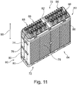
- FIG. 11 shows a further embodiment of an electric heater 70 in a perspective view.
- the electric heater 70 has a housing 72.
- the housing 72 has two housing half shells 74 and 76.
- Each of the housing halves 74 and 76 has a housing side member 78, housing front parts 80, a housing cover 82 and a housing bottom 84.
- the heating elements 88 preferably have PTC heating elements 88 (Positive Temperature Coefficient).
- the heating elements 88 are preferably arranged in an extension direction 90 of the electric heating device 70, indicated by the arrow 90, substantially parallel to one another in a row and form a heating block (not shown).
- the heating elements 88 may be arranged in a row or in two adjacent rows.
- FIG. 12 shows an enlarged view of the electric heater 70 with unclosed openings 86. Like parts are designated by the same reference numerals, as in FIG. 11 ,
- FIG. 13 shows the heater 70, wherein the heating elements 88 are each received in a sealing element 92.
- the sealing element 92 is designed as a molded seal or as an adhesive-spring combination.
- the sealing element 92 is in this case arranged directly on the housing cover 82 and / or the housing bottom 84, not shown. As a result, a tight connection between the heating element 88 and the housing cover 82 in the region of the openings 86 is realized. This can prevent the ingress of dust and / or dirt and water.
- the sealing member 92 may be made of a liquid silicone rubber. Alternatively, the sealing member 92 may be a silicone adhesive and / or silicone gel.
- the sealing element 92 is a flexible seal and is mounted directly on the housing 72, in particular on the housing cover 82 in the region of the openings 86.
- FIG. 14 shows in perspective a detailed view of the electric heater 70 (top view) and the heating elements 88 (bottom view).
- the heating elements 88 are designed as PTC radiator 88 and arranged in two juxtaposed rows.
- the heating elements 88 each have a connection 89, by means of which the heating elements 88 can be connected to a power supply, not shown.
- the housing 72 is preferably made of a plastic and the heating elements 88 are received in openings 86 and arranged. At the designated by arrows 91 areas of the housing 72 no silicone is arranged.
- FIG. 15 shows a perspective view of the electric heater 70 of FIG. 14 , Same objects are denoted by the same reference numerals designated.
- the housing is encapsulated with silicone.
- the sealing element 92 is formed by encapsulation with silicone.
- the housing 72 is encapsulated with silicone both in the cover area and in the floor area.
- the upper portion of the plastic frame of the housing 72 is shown spaced apart from the housing half shells 74 and 76 with the seal member 92.
- the housing 72 can be additionally encapsulated with silicone.
Description
Die Erfindung betrifft eine elektrische Heizvorrichtung, insbesondere für ein Kraftfahrzeug.The invention relates to an electric heater, in particular for a motor vehicle.
Elektrische Heizvorrichtungen sind im Stand der Technik bekannt und werden auch als elektrische Zusatzheizungen in einem Kraftfahrzeug eingesetzt. Insbesondere bei Kraftfahrzeugen mit einem verbrauchsoptimierten Verbrennungsmotor und/oder bei einem Elektrofahrzeug werden elektrische Heizvorrichtungen zur Beheizung eines Fahrgastinnenraums des Kraftfahrzeugs und/oder des Motors eingesetzt. Hierbei wird die elektrische Zusatzheizung nach dem Starten des Verbrennungsmotors verwendet, solange der Verbrennungsmotor noch keine ausreichende Wärmeenergie zur Verfügung stellen kann. Die Beheizung des Verbrennungsmotors dient der schnelleren Erreichung eines optimalen Betriebspunkts.Electric heaters are known in the art and are also used as electrical booster heaters in a motor vehicle. In particular, in motor vehicles with a consumption-optimized internal combustion engine and / or in an electric vehicle, electrical heating devices are used for heating a passenger compartment of the motor vehicle and / or the motor. Here, the electric auxiliary heater is used after starting the engine, as long as the engine can not provide sufficient heat energy available. The heating of the internal combustion engine serves the faster achievement of an optimal operating point.
Die Verwendung der elektrischen Heizvorrichtung kann auch für eine Vielzahl von anderen Einsatzzwecken außerhalb des Kraftfahrzeuges vorgesehen sein, beispielsweise im Bereich von Hausinstallationen, zur Raumklimatisierung, in Industrieanlagen und in vielen Bereichen mehr.The use of the electric heating device may also be provided for a variety of other purposes outside the motor vehicle, for example in the field of home installations, for air conditioning, in industrial plants and in many areas more.
Aus dem Dokument
Das Dokument
Das Dokument
Es ist die Aufgabe der Erfindung, eine verbesserte elektrische Heizvorrichtung zu schaffen.It is the object of the invention to provide an improved electric heating device.
Die Aufgabe wird mit einer elektrischen Heizvorrichtung mit den Merkmalen von Anspruch 1 gelöst.The object is achieved with an electric heater with the features of claim 1.
Das Dichtungselement ist bevorzugt dichtend und ohne Spaltbildung an dem Gehäusedeckel und am Gehäuseboden im Bereich der Öffnung angeordnet. Mittels des Dichtungselements kann somit eine dichte Verbindung zwischen dem Heizelement und dem Gehäuse hergestellt werden. Dadurch kann ein Eindringen von Partikeln, Staub bzw. allgemein Schmutz und/oder Wasser verhindert werden. Das Dichtungselement kann hierbei ein elastisches Dichtungselement, beispielsweise eine Formdichtung, aus einem elastischen Material, sein. Das Dichtungselement kann auch eine Klebstoff-Feder-Verbindung sein, die eine gewisse Elastizität aufweist. Alternativ kann das Dichtungselement ein relativ starres Dichtungselement sein, das mit dem Gehäusedeckel im Bereich der Öffnung durch eine Fase an dem Gehäuse und/oder dem Dichtungselement eine dichte Verbindungszone ausbildet. Somit kann mit dem Dichtungselement die dichte Verbindungszone zwischen dem Heizelement und dem Gehäusedeckel und dem Gehäuseboden hergestellt werden.The sealing element is preferably arranged sealingly and without gap formation on the housing cover and on the housing bottom in the region of the opening. By means of the sealing element can thus be made a tight connection between the heating element and the housing. This can prevent the penetration of particles, dust or dirt and / or water in general. The sealing element can in this case an elastic sealing element, for example a molded seal, from a elastic material, be. The sealing element can also be an adhesive-spring connection which has a certain elasticity. Alternatively, the sealing element may be a relatively rigid sealing element, which forms a sealed connection zone with the housing cover in the region of the opening by a chamfer on the housing and / or the sealing element. Thus, with the sealing element, the dense connection zone between the heating element and the housing cover and the housing bottom can be produced.
Es werden nicht mehrere Dichtungsteilelemente benötigt, wie dies im Stand der Technik der Fall ist. Das Dichtungselement ist hierbei mit dem Gehäusedeckel, insbesondere im Bereich der Öffnung, verbunden oder verbindbar. Im nicht montierten Zustand der elektrischen Heizvorrichtung liegen das mindestens eine Heizelement, weiches bevorzugt ein Aluminiumgehäuse und darin angeordnete PTC-Heizelemente aufweist, das zugehörige Dichtungselement und das Gehäuse separat vor. Das Dichtungselement ist nicht mit dem Heizelement verbunden, insbesondere nicht mit den PTC-Heizelementen verbunden. Beim Montieren kann das Heizelement in das Gehäuse eingesetzt oder angeordnet werden, das Dichtungselement kann auf dem mindestens einen Heizelement angeordnet werden und das Gehäuse kann verschlossen werden. Ein Anschlusselement an einer elektrischen Versorgungseinrichtung des Heizelementes kann hierbei bevorzugt durch das Dichtungselement hindurchgeschoben werden.It does not require a plurality of sealing element parts, as is the case in the prior art. The sealing element is in this case connected to the housing cover, in particular in the region of the opening, or connectable. In the unassembled state of the electric heating device, the at least one heating element, which preferably has an aluminum housing and PTC heating elements arranged therein, are the associated sealing element and the housing separately. The sealing element is not connected to the heating element, in particular not connected to the PTC heating elements. When mounting the heating element can be inserted or arranged in the housing, the sealing element can be arranged on the at least one heating element and the housing can be closed. A connection element on an electrical supply device of the heating element can in this case preferably be pushed through the sealing element.
Erfindungsgemäß sind sowohl in dem Gehäusedeckel als auch in dem Gehäuseboden Öffnungen vorgesehen. In jeder Öffnung ist ein Dichtungselement zur Aufnahme des Heizelementes vorgesehen. Die einzelnen Dichtungselemente können aber auch verbunden sein und als ein einstückiges Dichtungselement vorliegen. Die Heizelemente sind bevorzugt in einer Reihe neben- bzw. hintereinander angeordnet und bilden einen Heizblock aus. Die Heizelemente können alternativ oder zusätzlich auch in mehreren nebeneinanderliegenden Reihen angeordnet sein.According to the invention openings are provided both in the housing cover and in the housing bottom. In every opening is one Seal provided for receiving the heating element. However, the individual sealing elements can also be connected and present as a one-piece sealing element. The heating elements are preferably arranged in a row next to or behind each other and form a heating block. The heating elements may alternatively or additionally be arranged in a plurality of adjacent rows.
Hierbei kann am Gehäusedeckel und/oder an dem Gehäuseboden, insbesondere an einem inneren Umfang im Bereich der Öffnung im Gehäusedeckel und/oder Gehäuseboden eine Fase vorgesehen sein. Insbesondere ist die Fase jeweils an einem Innenrand der Öffnung angeordnet. Hierbei kann die Fase eine durchgehende Fase sein oder abschnittsweise im Bereich der Öffnung angeordnet sein.In this case, a bevel can be provided on the housing cover and / or on the housing bottom, in particular on an inner circumference in the region of the opening in the housing cover and / or housing bottom. In particular, the chamfer is arranged in each case on an inner edge of the opening. In this case, the chamfer can be a continuous chamfer or arranged in sections in the region of the opening.
Ferner ist bevorzugt vorgesehen, dass an einem Dichtungselementumfang jedes Dichtungselementes eine Fase angeordnet ist. Die Fase des Dichtungselementes und die Fase des Gehäusedeckels und/oder Gehäusebodens sind derart gestaltet, dass eine formschlüssige Verbindung zwischen dem Dichtungselement und dem Gehäusedeckel und/oder dem Gehäuseboden im Bereich der jeweiligen Öffnung realisierbar ist.Furthermore, it is preferably provided that a chamfer is arranged on a sealing element circumference of each sealing element. The chamfer of the sealing element and the chamfer of the housing cover and / or housing bottom are designed such that a positive connection between the sealing element and the housing cover and / or the housing bottom in the region of the respective opening can be realized.
Die Fase ist bevorzugt eine Formgebung an einer abgeschrägten Fläche und/oder Kante der Innenrandfläche des Gehäusedeckels und/oder Gehäusebodens im Bereich der Öffnung. Die Fase kann hierbei einen Winkel von ungefähr 30° bis 70°, bevorzugt 45°, zu der der Öffnung zugewandten Ebene des Gehäusedeckels und/oder Gehäusebodens aufweisen. Die Innenrandfläche erstreckt sich hierbei bevorzugt im Wesentlichen senkrecht zur Erstreckungsrichtung des Gehäusedeckels. Das Dichtungselement kann eine gewisse Elastizität aufweisen und komprimierbar sein. Dadurch kann es beim Montieren zu einer sogenannten Presspassung kommen. Hierbei kann es ermöglicht sein, dass ein geringerer Kraftaufwand notwendig ist, um das Dichtungselement optimal in die Öffnung im Gehäusedeckel und Gehäuseboden anzuordnen, insbesondere einzupassen. Dadurch kann das Heizelement jeweils optimal in der Öffnung aufgenommen und in dieser sicher angeordnet werden. Die Fase kann neben der Realisierung der dichten Verbindung auch die Positionierung des Dichtelementes im Gehäusedeckel und/oder Gehäuseboden verbessern.The chamfer is preferably a shape on a chamfered surface and / or edge of the inner edge surface of the housing cover and / or housing bottom in the region of the opening. In this case, the chamfer can have an angle of approximately 30 ° to 70 °, preferably 45 °, to the plane of the housing cover and / or housing bottom facing the opening. The inner edge surface preferably extends in this case substantially perpendicular to the extension direction of the housing cover. The sealing element may have a certain elasticity and be compressible. This can lead to a so-called press fit when mounting. It may be possible that a lesser amount of force is necessary to the Optimal sealing element to be arranged in the opening in the housing cover and housing bottom, in particular to fit. As a result, the heating element can be optimally accommodated in the opening and securely arranged in it. In addition to realizing the tight connection, the chamfer can also improve the positioning of the sealing element in the housing cover and / or housing bottom.
In einer Ausgestaltung der elektrischen Heizvorrichtung kann an einer Verbindungslinie zwischen dem Heizelement und dem Gehäusedeckel und/oder dem Gehäuseboden im Bereich der Öffnung ein Silikon-Kleber und/oder Silikon-Gel und/oder flüssiges Silikon angeordnet sein. Hierbei haben der Silikon-Kleber und/oder das Silikon-Gel die Funktion des Dichtungselements. Hierdurch kann die formschlüssige Verbindung optimiert werden. Die Dichtungsfunktion zwischen dem Dichtungselement und dem Gehäusedeckel und Gehäuseboden kann stabil und insgesamt dicht gegenüber Staub, Schmutz und Feuchtigkeit sein.In one configuration of the electric heating device, a silicone adhesive and / or silicone gel and / or liquid silicone may be arranged in the region of the opening on a connecting line between the heating element and the housing cover and / or the housing bottom. Here, the silicone adhesive and / or the silicone gel have the function of the sealing element. As a result, the positive connection can be optimized. The sealing function between the sealing element and the housing cover and housing bottom can be stable and overall tight against dust, dirt and moisture.
Das Gehäuse der elektrischen Heizvorrichtung weist zwei Gehäusehalbschalen auf, wobei die Gehäusehalbschalen im Wesentlichen senkrecht zum Gehäusedeckel und/oder zum Gehäuseboden angeordnet sind. Die Erstreckungsrichtung der Heizelemente ist bevorzugt entlang der Gehäusehalbschalen und somit im Wesentlichen senkrecht zum Gehäusedeckel und/oder Gehäuseboden gerichtet. An der Stoßkante der beiden Gehäusehalbschalen kann bevorzugt ein zweites zusätzliches Dichtungselement angeordnet sein.The housing of the electrical heating device has two housing half-shells, wherein the housing half-shells are arranged substantially perpendicular to the housing cover and / or to the housing bottom. The extension direction of the heating elements is preferably directed along the housing half-shells and thus substantially perpendicular to the housing cover and / or housing bottom. At the abutting edge of the two housing half-shells, a second additional sealing element may preferably be arranged.
Erfindungsgemäß ist das Gehäuse ein Kunststoff-Gehäuse, wobei zumindest die Gehäusehalbschalen aus einem Kunststoffmaterial gefertigt sind. Hierdurch kann ein elektrisch isolierendes Gehäuse realisiert werden. Außerdem weist das Gehäuse ein relativ geringes Gewicht auf Grund des niedrigen spezifischen Gewichts des Kunststoffmaterials auf.According to the invention, the housing is a plastic housing, wherein at least the housing half-shells are made of a plastic material. In this way, an electrically insulating housing can be realized. In addition, the housing has a relatively low weight due to the low specific gravity of the plastic material.
Bevorzugt weist jedes Heizelement der elektrischen Heizvorrichtung ein PTC-Heizelement auf, insbesondere ein HV-PTC-Heizelement. Das PTC-Heizelement weist einen positiven Temperaturkoeffizienten auf, wobei das HV-PTC-Heizelement mit einer Spannung größer als 60 V betrieben werden kann. Das PTC-Heizelement selbst ist bevorzugt in einem Aluminiumgehäuse angeordnet.Each heating element of the electric heating device preferably has a PTC heating element, in particular a HV PTC heating element. The PTC heater has a positive temperature coefficient, and the HV-PTC heater can be operated with a voltage greater than 60V. The PTC heating element itself is preferably arranged in an aluminum housing.
Die Heizelemente, insbesondere die im Aluminiumgehäuse angeordneten PTC-Heizelemente mit Anschlüssen, bilden bevorzugt einen Heizblock aus. Hierbei kann der Heizblock als ein Element aus dem Gehäuse entnommen werden.The heating elements, in particular the PTC heating elements with terminals arranged in the aluminum housing, preferably form a heating block. In this case, the heating block can be removed as an element from the housing.
Die Aufgabe wird ebenfalls mit einem Kraftfahrzeug mit einer erfindungsgemäßen elektrischen Heizvorrichtung gelöst. Hierbei sind die Heizelemente, insbesondere die PTC-Heizelemente, jeweils in einem Dichtungselement in dem Gehäusedeckel und im Gehäuseboden angeordnet. Das jeweilige Dichtungselement ist eine Formdichtung und/oder eine Kleber/Feder-Kombination. Alternativ oder zusätzlich können der Gehäusedeckel und/oder der Gehäuseboden eine Fase an einer Innenkante einer das Dichtungselement und das Heizelement aufnehmenden Öffnung aufweisen. Zusätzlich kann das Dichtungselement ebenfalls eine Fase aufweisen, die passgenau zur Fase des Gehäusedeckels und/oder des Gehäusebodens ausgestaltet ist.The object is likewise achieved with a motor vehicle having an electric heating device according to the invention. In this case, the heating elements, in particular the PTC heating elements, are each arranged in a sealing element in the housing cover and in the housing bottom. The respective sealing element is a molded seal and / or a glue / spring combination. Alternatively or additionally, the housing cover and / or the housing bottom may have a chamfer on an inner edge of an opening receiving the sealing element and the heating element. In addition, the sealing element may also have a chamfer, which is designed to fit the chamfer of the housing cover and / or the housing bottom.
Weitere vorteilhafte Ausgestaltungen sind durch die nachfolgende Figurenbeschreibung und durch die Unteransprüche beschrieben.Further advantageous embodiments are described by the following description of the figures and by the subclaims.
Nachstehend wird die Erfindung auf der Grundlage zumindest eines Ausführungsbeispiels anhand der Figuren der Zeichnung näher erläutert. Es zeigen:
- Fig. 1
- ein erstes Ausführungsbeispiel einer erfindungsgemäßen elektrischen Heizvorrichtung in perspektivischer Darstellung,
- Fig. 2
- eine Gehäusehalbschale des Kunststoffrahmens der elektrischen Heizvorrichtung in perspektivischer Darstellung,
- Fig. 3
- einen Heizblock mit Heizelementen der elektrischen Heizvorrichtung in perspektivischer Darstellung,
- Fig. 4
- eine Ansicht auf einen Gehäusedeckel der elektrischen Heizvorrichtung,
- Fig. 5
- das Heizelement (rechts) und den Heizblock (links) mit Heizelementen ohne Dichtungselement,
- Fig. 6
- den Heizblock ohne Dichtungselemente (oben) und ein Heizblock mit Dichtungselementen (mittlere Figur) sowie eine Draufsicht auf den Gehäusedeckel (unten),
- Fig. 7
- einen Teilausschnitt des Heizblocks und zwei Gehäusehalbschalen in Explosionsdarstellung (oben), das Gehäuse mit Dichtungselementen in zusammenmontiertem Zustand in einer perspektivischen Ansicht (Mitte) und eine Draufsicht auf den Gehäusedeckel (unten),
- Fig. 8
- den Heizblock mit Dichtungselementen und zwei Gehäusehalbschalen in Explosionsdarstellung (oben), das Gehäuse mit Dichtungselementen in zusammenmontiertem Zustand in einer perspektivischen Ansicht (Mitte) und eine Draufsicht auf den Gehäusedeckel (unten),
- Fig. 9
- den Heizblock in Explosionsdarstellung und einen Ausschnitt aus dem Gehäusedeckel,
- Fig. 10
- eine perspektivische Draufsicht auf das Gehäuse mit unterschiedlichen Dichtungselementen,
- Fig. 11
- ein weiteres Ausführungsbeispiel einer elektrischen Heizvorrichtung mit Heizelementen,
- Fig. 12
- eine Detailansicht der elektrischen Heizvorrichtung von
Figur 11 , - Fig. 13
- eine Detailansicht der elektrischen
Heizvorrichtung von Figur 12 mit Dichtungselementen, - Fig. 14
- eine perspektivische Ansicht der elektrischen Heizvorrichtung (oben) und der Heizelemente (unten),
- Fig. 15
- eine perspektivische Ansicht der elektrischen Heizvorrichtung (oben) mit Dichtungselement und der Heizelemente (unten),
- Fig. 16
- eine perspektivische Darstellung des Kunststoffgehäuses mit Dichtungselement.
- Fig. 1
- A first embodiment of an electric heater according to the invention in a perspective view,
- Fig. 2
- a housing half-shell of the plastic frame of the electric heater in a perspective view,
- Fig. 3
- a heating block with heating elements of the electric heater in a perspective view,
- Fig. 4
- a view of a housing cover of the electric heater,
- Fig. 5
- the heating element (right) and the heating block (left) with heating elements without sealing element,
- Fig. 6
- the heating block without sealing elements (top) and a heating block with sealing elements (middle figure) and a plan view of the housing cover (bottom),
- Fig. 7
- a partial section of the heating block and two housing half-shells in exploded view (top), the housing with sealing elements in the assembled state in a perspective view (center) and a plan view of the housing cover (bottom),
- Fig. 8
- the heating block with sealing elements and two housing half-shells in exploded view (top), the housing with sealing elements in assembled state in a perspective view (center) and a plan view of the housing cover (bottom),
- Fig. 9
- the heating block in exploded view and a section of the housing cover,
- Fig. 10
- a perspective top view of the housing with different sealing elements,
- Fig. 11
- Another embodiment of an electric heater with heating elements,
- Fig. 12
- a detailed view of the electric heater of
FIG. 11 . - Fig. 13
- a detailed view of the electric heater of
FIG. 12 with sealing elements, - Fig. 14
- a perspective view of the electric heater (top) and the heating elements (bottom),
- Fig. 15
- a perspective view of the electric heater (above) with sealing element and the heating elements (below),
- Fig. 16
- a perspective view of the plastic housing with sealing element.
An der mit dem Pfeil 44 und dem Pfeil 46 markierten Position kann Schmutz, und/oder Partikel und/oder Staub und/oder Wasser durch einen offenen Bereich 45 in das Aluminiumgehäuse 38 eindringen und die PTC-Heizelemente 36 schädigen. Der offene Bereich 45a ist im Deckelbereich 29 angeordnet und der offene Bereich 45b ist im Bodenbereich 27 angeordnet.At the position marked with the arrow 44 and the
In
Claims (8)
- An electric heating device with heating elements (36, 88), disposed in a housing (12, 56, 72), wherein the housing (12, 56, 72) has a housing cover (20, 82), a housing base (22, 84), a plastic frame (14), two housing side elements (16) and two housing front elements (18), wherein in the housing base and in the housing cover, openings (24, 86) are provided in which a respective heating element (36, 88) with a sealing element is disposed, wherein in the respective opening (24, 86), a sealing element (26, 54, 67, 69, 92) is provided in which the respective heating element (36, 88) is disposed, wherein the housing (12, 56, 72) has two housing half-shells (48, 50; 60, 62), wherein the housing half-shells (48, 50; 60, 62) are disposed substantially perpendicular to the housing cover (20, 82) and to the housing base (22, 84).
- The electric heating device according to claim 1, characterised in that a bevel (34, 34a, 34b, 34c, 34d) is provided on the housing cover (20, 82) and/or on the housing base at an inner perimeter in the area of the opening (24, 86) of the housing cover (20, 82) and/or of the housing base (22, 84).
- The electric heating device according to one of the preceding claims, characterised in that a bevel (28, 28a, 28b, 28c, 28d) is provided on the sealing element perimeter, wherein the bevel (28, 28a, 28b, 28c, 28d) of the sealing element (26) and the bevel (34, 34a, 34b, 34c, 34d) of the housing cover (20) and/or of the housing base interact.
- The electric heating device according to one of the preceding claims, characterised in that the housing (20, 56, 72) is a plastic housing, wherein at least the housing half-shells (48, 50; 60, 62) are fabricated of plastic.
- The electric heating device according to one of the preceding claims, characterised in that the housing (20, 56, 72) is a plastic housing.
- The electric heating device according to one of the preceding claims, characterised in that the heating elements (36, 88) respectively are a PTC heating element or a HV PTC heating element.
- The electric heating device according to one of the preceding claims, characterised in that the heating elements (36, 88) or the PTC heating elements form a heating block (42).
- A motor vehicle having an electric heating device (10, 70) according to one of claims 1 to 7.
Priority Applications (2)
| Application Number | Priority Date | Filing Date | Title |
|---|---|---|---|
| EP14173063.0A EP2957840B1 (en) | 2014-06-18 | 2014-06-18 | Electric heating device |
| US14/742,767 US9894715B2 (en) | 2014-06-18 | 2015-06-18 | Electric heating device |
Applications Claiming Priority (1)
| Application Number | Priority Date | Filing Date | Title |
|---|---|---|---|
| EP14173063.0A EP2957840B1 (en) | 2014-06-18 | 2014-06-18 | Electric heating device |
Publications (2)
| Publication Number | Publication Date |
|---|---|
| EP2957840A1 EP2957840A1 (en) | 2015-12-23 |
| EP2957840B1 true EP2957840B1 (en) | 2019-10-02 |
Family
ID=50979573
Family Applications (1)
| Application Number | Title | Priority Date | Filing Date |
|---|---|---|---|
| EP14173063.0A Active EP2957840B1 (en) | 2014-06-18 | 2014-06-18 | Electric heating device |
Country Status (2)
| Country | Link |
|---|---|
| US (1) | US9894715B2 (en) |
| EP (1) | EP2957840B1 (en) |
Families Citing this family (4)
| Publication number | Priority date | Publication date | Assignee | Title |
|---|---|---|---|---|
| FR3075326B1 (en) * | 2017-12-19 | 2020-05-15 | Valeo Systemes Thermiques | HEATING DEVICE FOR AIR CONDITIONING UNIT, ESPECIALLY A MOTOR VEHICLE, AND AIR CONDITIONING HOUSING PROVIDED WITH SUCH A HEATING DEVICE |
| US11760056B2 (en) | 2018-12-05 | 2023-09-19 | Battelle Memorial Institute | Flexible foam resistive heaters and methods of making flexible resistive heaters |
| CN114643831B (en) * | 2022-04-08 | 2024-02-13 | 安徽省宁国市天成电气有限公司 | New energy automobile heater |
| FR3136140A1 (en) * | 2022-05-24 | 2023-12-01 | Valeo Systemes Thermiques | Electric radiator with overmolded retention gasket |
Citations (1)
| Publication number | Priority date | Publication date | Assignee | Title |
|---|---|---|---|---|
| DE102013103433A1 (en) * | 2012-04-13 | 2013-10-17 | Dbk David + Baader Gmbh | Electric auxiliary heater for motor vehicle, has sealing unit has two form-seals, which sealingly surround control housing-side end portion and distal end portion of heating housing |
Family Cites Families (6)
| Publication number | Priority date | Publication date | Assignee | Title |
|---|---|---|---|---|
| US1992787A (en) * | 1932-08-05 | 1935-02-26 | Edison General Elec Appliance | Electric heater |
| DE502006003627D1 (en) | 2006-10-25 | 2009-06-10 | Catem Gmbh & Co Kg | Heat generating element for an electric heater and method of making the same |
| DE502007005351D1 (en) | 2007-07-20 | 2010-11-25 | Eberspaecher Catem Gmbh & Co K | Electric heating device, in particular for motor vehicles |
| KR20090098029A (en) | 2008-03-13 | 2009-09-17 | 센젠 산유안 일렉트로닉 캄퍼니 리미티드 | Enclosed type heater with positive temperature coefficient thermister |
| EP2428747B1 (en) * | 2010-09-13 | 2015-04-08 | MAHLE Behr GmbH & Co. KG | Heat exchanger |
| EP2607121B2 (en) | 2011-12-22 | 2020-07-08 | Eberspächer catem GmbH & Co. KG | Electric heating device, in particular for a motor vehicle |
-
2014
- 2014-06-18 EP EP14173063.0A patent/EP2957840B1/en active Active
-
2015
- 2015-06-18 US US14/742,767 patent/US9894715B2/en active Active
Patent Citations (1)
| Publication number | Priority date | Publication date | Assignee | Title |
|---|---|---|---|---|
| DE102013103433A1 (en) * | 2012-04-13 | 2013-10-17 | Dbk David + Baader Gmbh | Electric auxiliary heater for motor vehicle, has sealing unit has two form-seals, which sealingly surround control housing-side end portion and distal end portion of heating housing |
Also Published As
| Publication number | Publication date |
|---|---|
| EP2957840A1 (en) | 2015-12-23 |
| US9894715B2 (en) | 2018-02-13 |
| US20150373784A1 (en) | 2015-12-24 |
Similar Documents
| Publication | Publication Date | Title |
|---|---|---|
| EP2017548B1 (en) | Electric heating device, in particular for motor vehicles | |
| EP1768457B1 (en) | Heat generating element of a heating device | |
| EP1916874B1 (en) | Heating element of a heating device | |
| EP3334243B1 (en) | Electric heating device | |
| EP2607121B2 (en) | Electric heating device, in particular for a motor vehicle | |
| EP1768459B1 (en) | Heat generating element of a heating device | |
| EP2873296B1 (en) | Heat generating element | |
| EP2957840B1 (en) | Electric heating device | |
| EP2884817B1 (en) | Electric heating device and method for its production | |
| DE4133879A1 (en) | ELECTROHYDRAULIC UNIT FOR PRESSURE CONTROL IN VEHICLE BRAKE SYSTEMS | |
| DE4434613A1 (en) | Electric heating device, in particular for a motor vehicle | |
| EP2607808A1 (en) | Heating element | |
| EP3493650A1 (en) | Electric heating device | |
| DE102019205848A1 (en) | PTC heating element and electrical heating device with such a PTC heating element and method for producing a PTC heating element | |
| EP2608631A1 (en) | Element which produces heat | |
| EP2608633A1 (en) | Element which produces heat | |
| EP2884199B1 (en) | Electric heating device | |
| DE102013103433A1 (en) | Electric auxiliary heater for motor vehicle, has sealing unit has two form-seals, which sealingly surround control housing-side end portion and distal end portion of heating housing | |
| EP2884198B1 (en) | Electric heating device | |
| DE102013000628B4 (en) | Holding frame of a fresh air flap of a motor vehicle and fresh air flap with holding frame | |
| DE202010018115U1 (en) | Plug element with locking seal | |
| DE102019204472A1 (en) | Heat-generating element and electrical heating device containing such | |
| EP3598847B1 (en) | Heat-generating element and method for producing the same | |
| DE102015013508A1 (en) | battery | |
| DE102014218787A1 (en) | Thermoelectric device, in particular thermoelectric generator, for a motor vehicle |
Legal Events
| Date | Code | Title | Description |
|---|---|---|---|
| PUAI | Public reference made under article 153(3) epc to a published international application that has entered the european phase |
Free format text: ORIGINAL CODE: 0009012 |
|
| AK | Designated contracting states |
Kind code of ref document: A1 Designated state(s): AL AT BE BG CH CY CZ DE DK EE ES FI FR GB GR HR HU IE IS IT LI LT LU LV MC MK MT NL NO PL PT RO RS SE SI SK SM TR |
|
| AX | Request for extension of the european patent |
Extension state: BA ME |
|
| 17P | Request for examination filed |
Effective date: 20160623 |
|
| RBV | Designated contracting states (corrected) |
Designated state(s): AL AT BE BG CH CY CZ DE DK EE ES FI FR GB GR HR HU IE IS IT LI LT LU LV MC MK MT NL NO PL PT RO RS SE SI SK SM TR |
|
| STAA | Information on the status of an ep patent application or granted ep patent |
Free format text: STATUS: EXAMINATION IS IN PROGRESS |
|
| 17Q | First examination report despatched |
Effective date: 20170710 |
|
| RIC1 | Information provided on ipc code assigned before grant |
Ipc: F24H 3/04 20060101AFI20190405BHEP Ipc: F24H 9/18 20060101ALI20190405BHEP Ipc: B60H 1/22 20060101ALI20190405BHEP |
|
| GRAP | Despatch of communication of intention to grant a patent |
Free format text: ORIGINAL CODE: EPIDOSNIGR1 |
|
| STAA | Information on the status of an ep patent application or granted ep patent |
Free format text: STATUS: GRANT OF PATENT IS INTENDED |
|
| INTG | Intention to grant announced |
Effective date: 20190517 |
|
| GRAS | Grant fee paid |
Free format text: ORIGINAL CODE: EPIDOSNIGR3 |
|
| GRAJ | Information related to disapproval of communication of intention to grant by the applicant or resumption of examination proceedings by the epo deleted |
Free format text: ORIGINAL CODE: EPIDOSDIGR1 |
|
| GRAL | Information related to payment of fee for publishing/printing deleted |
Free format text: ORIGINAL CODE: EPIDOSDIGR3 |
|
| STAA | Information on the status of an ep patent application or granted ep patent |
Free format text: STATUS: EXAMINATION IS IN PROGRESS |
|
| GRAR | Information related to intention to grant a patent recorded |
Free format text: ORIGINAL CODE: EPIDOSNIGR71 |
|
| STAA | Information on the status of an ep patent application or granted ep patent |
Free format text: STATUS: GRANT OF PATENT IS INTENDED |
|
| GRAA | (expected) grant |
Free format text: ORIGINAL CODE: 0009210 |
|
| STAA | Information on the status of an ep patent application or granted ep patent |
Free format text: STATUS: THE PATENT HAS BEEN GRANTED |
|
| INTC | Intention to grant announced (deleted) | ||
| RIN1 | Information on inventor provided before grant (corrected) |
Inventor name: ZIRGEL, THOMAS |
|
| AK | Designated contracting states |
Kind code of ref document: B1 Designated state(s): AL AT BE BG CH CY CZ DE DK EE ES FI FR GB GR HR HU IE IS IT LI LT LU LV MC MK MT NL NO PL PT RO RS SE SI SK SM TR |
|
| INTG | Intention to grant announced |
Effective date: 20190823 |
|
| REG | Reference to a national code |
Ref country code: GB Ref legal event code: FG4D Free format text: NOT ENGLISH |
|
| REG | Reference to a national code |
Ref country code: CH Ref legal event code: EP Ref country code: AT Ref legal event code: REF Ref document number: 1186618 Country of ref document: AT Kind code of ref document: T Effective date: 20191015 |
|
| REG | Reference to a national code |
Ref country code: DE Ref legal event code: R096 Ref document number: 502014012744 Country of ref document: DE |
|
| REG | Reference to a national code |
Ref country code: IE Ref legal event code: FG4D Free format text: LANGUAGE OF EP DOCUMENT: GERMAN |
|
| REG | Reference to a national code |
Ref country code: NL Ref legal event code: MP Effective date: 20191002 |
|
| REG | Reference to a national code |
Ref country code: LT Ref legal event code: MG4D |
|
| PG25 | Lapsed in a contracting state [announced via postgrant information from national office to epo] |
Ref country code: PT Free format text: LAPSE BECAUSE OF FAILURE TO SUBMIT A TRANSLATION OF THE DESCRIPTION OR TO PAY THE FEE WITHIN THE PRESCRIBED TIME-LIMIT Effective date: 20200203 Ref country code: FI Free format text: LAPSE BECAUSE OF FAILURE TO SUBMIT A TRANSLATION OF THE DESCRIPTION OR TO PAY THE FEE WITHIN THE PRESCRIBED TIME-LIMIT Effective date: 20191002 Ref country code: NO Free format text: LAPSE BECAUSE OF FAILURE TO SUBMIT A TRANSLATION OF THE DESCRIPTION OR TO PAY THE FEE WITHIN THE PRESCRIBED TIME-LIMIT Effective date: 20200102 Ref country code: BG Free format text: LAPSE BECAUSE OF FAILURE TO SUBMIT A TRANSLATION OF THE DESCRIPTION OR TO PAY THE FEE WITHIN THE PRESCRIBED TIME-LIMIT Effective date: 20200102 Ref country code: SE Free format text: LAPSE BECAUSE OF FAILURE TO SUBMIT A TRANSLATION OF THE DESCRIPTION OR TO PAY THE FEE WITHIN THE PRESCRIBED TIME-LIMIT Effective date: 20191002 Ref country code: LV Free format text: LAPSE BECAUSE OF FAILURE TO SUBMIT A TRANSLATION OF THE DESCRIPTION OR TO PAY THE FEE WITHIN THE PRESCRIBED TIME-LIMIT Effective date: 20191002 Ref country code: NL Free format text: LAPSE BECAUSE OF FAILURE TO SUBMIT A TRANSLATION OF THE DESCRIPTION OR TO PAY THE FEE WITHIN THE PRESCRIBED TIME-LIMIT Effective date: 20191002 Ref country code: LT Free format text: LAPSE BECAUSE OF FAILURE TO SUBMIT A TRANSLATION OF THE DESCRIPTION OR TO PAY THE FEE WITHIN THE PRESCRIBED TIME-LIMIT Effective date: 20191002 Ref country code: GR Free format text: LAPSE BECAUSE OF FAILURE TO SUBMIT A TRANSLATION OF THE DESCRIPTION OR TO PAY THE FEE WITHIN THE PRESCRIBED TIME-LIMIT Effective date: 20200103 Ref country code: PL Free format text: LAPSE BECAUSE OF FAILURE TO SUBMIT A TRANSLATION OF THE DESCRIPTION OR TO PAY THE FEE WITHIN THE PRESCRIBED TIME-LIMIT Effective date: 20191002 Ref country code: ES Free format text: LAPSE BECAUSE OF FAILURE TO SUBMIT A TRANSLATION OF THE DESCRIPTION OR TO PAY THE FEE WITHIN THE PRESCRIBED TIME-LIMIT Effective date: 20191002 |
|
| PG25 | Lapsed in a contracting state [announced via postgrant information from national office to epo] |
Ref country code: CZ Free format text: LAPSE BECAUSE OF FAILURE TO SUBMIT A TRANSLATION OF THE DESCRIPTION OR TO PAY THE FEE WITHIN THE PRESCRIBED TIME-LIMIT Effective date: 20191002 Ref country code: IS Free format text: LAPSE BECAUSE OF FAILURE TO SUBMIT A TRANSLATION OF THE DESCRIPTION OR TO PAY THE FEE WITHIN THE PRESCRIBED TIME-LIMIT Effective date: 20200224 Ref country code: HR Free format text: LAPSE BECAUSE OF FAILURE TO SUBMIT A TRANSLATION OF THE DESCRIPTION OR TO PAY THE FEE WITHIN THE PRESCRIBED TIME-LIMIT Effective date: 20191002 Ref country code: RS Free format text: LAPSE BECAUSE OF FAILURE TO SUBMIT A TRANSLATION OF THE DESCRIPTION OR TO PAY THE FEE WITHIN THE PRESCRIBED TIME-LIMIT Effective date: 20191002 |
|
| PG25 | Lapsed in a contracting state [announced via postgrant information from national office to epo] |
Ref country code: AL Free format text: LAPSE BECAUSE OF FAILURE TO SUBMIT A TRANSLATION OF THE DESCRIPTION OR TO PAY THE FEE WITHIN THE PRESCRIBED TIME-LIMIT Effective date: 20191002 |
|
| REG | Reference to a national code |
Ref country code: DE Ref legal event code: R097 Ref document number: 502014012744 Country of ref document: DE |
|
| PG2D | Information on lapse in contracting state deleted |
Ref country code: IS |
|
| PG25 | Lapsed in a contracting state [announced via postgrant information from national office to epo] |
Ref country code: DK Free format text: LAPSE BECAUSE OF FAILURE TO SUBMIT A TRANSLATION OF THE DESCRIPTION OR TO PAY THE FEE WITHIN THE PRESCRIBED TIME-LIMIT Effective date: 20191002 Ref country code: RO Free format text: LAPSE BECAUSE OF FAILURE TO SUBMIT A TRANSLATION OF THE DESCRIPTION OR TO PAY THE FEE WITHIN THE PRESCRIBED TIME-LIMIT Effective date: 20191002 Ref country code: EE Free format text: LAPSE BECAUSE OF FAILURE TO SUBMIT A TRANSLATION OF THE DESCRIPTION OR TO PAY THE FEE WITHIN THE PRESCRIBED TIME-LIMIT Effective date: 20191002 Ref country code: IS Free format text: LAPSE BECAUSE OF FAILURE TO SUBMIT A TRANSLATION OF THE DESCRIPTION OR TO PAY THE FEE WITHIN THE PRESCRIBED TIME-LIMIT Effective date: 20200202 |
|
| PLBE | No opposition filed within time limit |
Free format text: ORIGINAL CODE: 0009261 |
|
| STAA | Information on the status of an ep patent application or granted ep patent |
Free format text: STATUS: NO OPPOSITION FILED WITHIN TIME LIMIT |
|
| PG25 | Lapsed in a contracting state [announced via postgrant information from national office to epo] |
Ref country code: SM Free format text: LAPSE BECAUSE OF FAILURE TO SUBMIT A TRANSLATION OF THE DESCRIPTION OR TO PAY THE FEE WITHIN THE PRESCRIBED TIME-LIMIT Effective date: 20191002 Ref country code: IT Free format text: LAPSE BECAUSE OF FAILURE TO SUBMIT A TRANSLATION OF THE DESCRIPTION OR TO PAY THE FEE WITHIN THE PRESCRIBED TIME-LIMIT Effective date: 20191002 Ref country code: SK Free format text: LAPSE BECAUSE OF FAILURE TO SUBMIT A TRANSLATION OF THE DESCRIPTION OR TO PAY THE FEE WITHIN THE PRESCRIBED TIME-LIMIT Effective date: 20191002 |
|
| 26N | No opposition filed |
Effective date: 20200703 |
|
| PG25 | Lapsed in a contracting state [announced via postgrant information from national office to epo] |
Ref country code: SI Free format text: LAPSE BECAUSE OF FAILURE TO SUBMIT A TRANSLATION OF THE DESCRIPTION OR TO PAY THE FEE WITHIN THE PRESCRIBED TIME-LIMIT Effective date: 20191002 |
|
| PG25 | Lapsed in a contracting state [announced via postgrant information from national office to epo] |
Ref country code: MC Free format text: LAPSE BECAUSE OF FAILURE TO SUBMIT A TRANSLATION OF THE DESCRIPTION OR TO PAY THE FEE WITHIN THE PRESCRIBED TIME-LIMIT Effective date: 20191002 |
|
| REG | Reference to a national code |
Ref country code: CH Ref legal event code: PL |
|
| GBPC | Gb: european patent ceased through non-payment of renewal fee |
Effective date: 20200618 |
|
| PG25 | Lapsed in a contracting state [announced via postgrant information from national office to epo] |
Ref country code: LU Free format text: LAPSE BECAUSE OF NON-PAYMENT OF DUE FEES Effective date: 20200618 |
|
| REG | Reference to a national code |
Ref country code: BE Ref legal event code: MM Effective date: 20200630 |
|
| PG25 | Lapsed in a contracting state [announced via postgrant information from national office to epo] |
Ref country code: LI Free format text: LAPSE BECAUSE OF NON-PAYMENT OF DUE FEES Effective date: 20200630 Ref country code: GB Free format text: LAPSE BECAUSE OF NON-PAYMENT OF DUE FEES Effective date: 20200618 Ref country code: IE Free format text: LAPSE BECAUSE OF NON-PAYMENT OF DUE FEES Effective date: 20200618 Ref country code: CH Free format text: LAPSE BECAUSE OF NON-PAYMENT OF DUE FEES Effective date: 20200630 Ref country code: FR Free format text: LAPSE BECAUSE OF NON-PAYMENT OF DUE FEES Effective date: 20200630 |
|
| PG25 | Lapsed in a contracting state [announced via postgrant information from national office to epo] |
Ref country code: BE Free format text: LAPSE BECAUSE OF NON-PAYMENT OF DUE FEES Effective date: 20200630 |
|
| REG | Reference to a national code |
Ref country code: AT Ref legal event code: MM01 Ref document number: 1186618 Country of ref document: AT Kind code of ref document: T Effective date: 20200618 |
|
| PG25 | Lapsed in a contracting state [announced via postgrant information from national office to epo] |
Ref country code: AT Free format text: LAPSE BECAUSE OF NON-PAYMENT OF DUE FEES Effective date: 20200618 |
|
| PG25 | Lapsed in a contracting state [announced via postgrant information from national office to epo] |
Ref country code: TR Free format text: LAPSE BECAUSE OF FAILURE TO SUBMIT A TRANSLATION OF THE DESCRIPTION OR TO PAY THE FEE WITHIN THE PRESCRIBED TIME-LIMIT Effective date: 20191002 Ref country code: MT Free format text: LAPSE BECAUSE OF FAILURE TO SUBMIT A TRANSLATION OF THE DESCRIPTION OR TO PAY THE FEE WITHIN THE PRESCRIBED TIME-LIMIT Effective date: 20191002 Ref country code: CY Free format text: LAPSE BECAUSE OF FAILURE TO SUBMIT A TRANSLATION OF THE DESCRIPTION OR TO PAY THE FEE WITHIN THE PRESCRIBED TIME-LIMIT Effective date: 20191002 |
|
| PG25 | Lapsed in a contracting state [announced via postgrant information from national office to epo] |
Ref country code: MK Free format text: LAPSE BECAUSE OF FAILURE TO SUBMIT A TRANSLATION OF THE DESCRIPTION OR TO PAY THE FEE WITHIN THE PRESCRIBED TIME-LIMIT Effective date: 20191002 |
|
| PGFP | Annual fee paid to national office [announced via postgrant information from national office to epo] |
Ref country code: DE Payment date: 20230620 Year of fee payment: 10 |