EP2952015B1 - State of charge indication in a hearing device - Google Patents
State of charge indication in a hearing device Download PDFInfo
- Publication number
- EP2952015B1 EP2952015B1 EP13702426.1A EP13702426A EP2952015B1 EP 2952015 B1 EP2952015 B1 EP 2952015B1 EP 13702426 A EP13702426 A EP 13702426A EP 2952015 B1 EP2952015 B1 EP 2952015B1
- Authority
- EP
- European Patent Office
- Prior art keywords
- signal
- rechargeable battery
- voltage
- batt
- hearing device
- Prior art date
- Legal status (The legal status is an assumption and is not a legal conclusion. Google has not performed a legal analysis and makes no representation as to the accuracy of the status listed.)
- Active
Links
- 230000006870 function Effects 0.000 claims description 42
- 238000000034 method Methods 0.000 claims description 15
- 238000005259 measurement Methods 0.000 claims description 8
- 230000001105 regulatory effect Effects 0.000 claims description 5
- 230000001419 dependent effect Effects 0.000 description 5
- 230000005540 biological transmission Effects 0.000 description 3
- 238000004891 communication Methods 0.000 description 2
- 206010048865 Hypoacusis Diseases 0.000 description 1
- WHXSMMKQMYFTQS-UHFFFAOYSA-N Lithium Chemical compound [Li] WHXSMMKQMYFTQS-UHFFFAOYSA-N 0.000 description 1
- 230000001276 controlling effect Effects 0.000 description 1
- 238000001514 detection method Methods 0.000 description 1
- 238000010586 diagram Methods 0.000 description 1
- 210000000613 ear canal Anatomy 0.000 description 1
- 230000006698 induction Effects 0.000 description 1
- 230000001939 inductive effect Effects 0.000 description 1
- 229910052744 lithium Inorganic materials 0.000 description 1
- 238000012544 monitoring process Methods 0.000 description 1
- 238000012545 processing Methods 0.000 description 1
- 230000005236 sound signal Effects 0.000 description 1
Images

Classifications
-
- H—ELECTRICITY
- H02—GENERATION; CONVERSION OR DISTRIBUTION OF ELECTRIC POWER
- H02J—CIRCUIT ARRANGEMENTS OR SYSTEMS FOR SUPPLYING OR DISTRIBUTING ELECTRIC POWER; SYSTEMS FOR STORING ELECTRIC ENERGY
- H02J7/00—Circuit arrangements for charging or depolarising batteries or for supplying loads from batteries
- H02J7/0047—Circuit arrangements for charging or depolarising batteries or for supplying loads from batteries with monitoring or indicating devices or circuits
- H02J7/0048—Detection of remaining charge capacity or state of charge [SOC]
-
- H—ELECTRICITY
- H04—ELECTRIC COMMUNICATION TECHNIQUE
- H04R—LOUDSPEAKERS, MICROPHONES, GRAMOPHONE PICK-UPS OR LIKE ACOUSTIC ELECTROMECHANICAL TRANSDUCERS; DEAF-AID SETS; PUBLIC ADDRESS SYSTEMS
- H04R25/00—Deaf-aid sets, i.e. electro-acoustic or electro-mechanical hearing aids; Electric tinnitus maskers providing an auditory perception
- H04R25/30—Monitoring or testing of hearing aids, e.g. functioning, settings, battery power
- H04R25/305—Self-monitoring or self-testing
-
- H—ELECTRICITY
- H04—ELECTRIC COMMUNICATION TECHNIQUE
- H04R—LOUDSPEAKERS, MICROPHONES, GRAMOPHONE PICK-UPS OR LIKE ACOUSTIC ELECTROMECHANICAL TRANSDUCERS; DEAF-AID SETS; PUBLIC ADDRESS SYSTEMS
- H04R2225/00—Details of deaf aids covered by H04R25/00, not provided for in any of its subgroups
- H04R2225/31—Aspects of the use of accumulators in hearing aids, e.g. rechargeable batteries or fuel cells
-
- H—ELECTRICITY
- H04—ELECTRIC COMMUNICATION TECHNIQUE
- H04R—LOUDSPEAKERS, MICROPHONES, GRAMOPHONE PICK-UPS OR LIKE ACOUSTIC ELECTROMECHANICAL TRANSDUCERS; DEAF-AID SETS; PUBLIC ADDRESS SYSTEMS
- H04R2225/00—Details of deaf aids covered by H04R25/00, not provided for in any of its subgroups
- H04R2225/33—Aspects relating to adaptation of the battery voltage, e.g. its regulation, increase or decrease
Definitions
- hearing devices were powered by primary cells such as zinc-air batteries, directly connected to the circuitry of the hearing device. Since the circuitry of such a hearing device is directly connected to the battery, the state of charge of the battery can be directly measured by the hearing device circuitry by measuring the voltage produced by the battery, and the user can be informed of the state of charge of the battery and be alerted once the voltage, and thus the state of charge, drops below a predefined level, indicating that the battery should be replaced. Replacing the battery frequently is expensive and can be difficult for persons with physical limitations.
- Rechargeable batteries also known as secondary cells
- secondary cells eliminate the requirement for frequent battery replacement, since they can be recharged, e.g. either by connecting the hearing device to a suitable external power supply, or by wireless transmission of power. This simplifies usage of the hearing device for the user.
- secondary cells can generate relatively high voltage levels, e.g. greater than 1.5 V, which can damage or destroy the sensitive circuitry of the hearing device.
- a battery power management system is often used to control charging of the battery and also to ensure constant voltage levels of the power supplied to the circuitry such that this voltage level does not exceed a threshold which may damage this circuitry.
- WO 00/79836 A1 describes a hearing device with an add-on module containing an accumulator.
- EP 2 672 731 A1 discloses a hearing instrument system with an accumulator.
- the accumulator provides energy to the hearing instrument and transmits state of charge information generated by an accumulator control facility to the hearing instrument by way of a respective communication link.
- the transmission of the state of charge information enables a reliable state of charge detection in the case of batteries, whose state of charge cannot be identified based on their voltage.
- hearing devices we understand hearing aids for the hard-of-hearing, communication devices such as earpieces for radios or music listening, active hearing protection for loud noises, and so on. Such hearing devices may be situated at least partially in the wearer's ear canal, and/or may comprise a unit situated behind the wearer's pinna.
- hearing device relates to the entire device, comprising battery, power management circuitry, and the term “function module” refers to the conventional hearing device components and circuitry such as signal processing circuitry, a receiver, microphone and/or reception coil, and so on.
- the object of the invention is attained by a hearing device according to the independent device claim.
- This hearing device comprises a function module as defined above.
- the hearing device further comprises a rechargeable battery and a battery power management unit.
- the battery power management unit comprises a voltage regulator in operative connection with the rechargeable battery for regulating and supplying a supply voltage to the function module.
- the battery power management unit comprises a control unit in operative connection with the voltage regulator and the rechargeable battery.
- the control unit is arranged to measure the output voltage of the rechargeable battery and also to control the supply voltage output by the voltage regulator.
- the control unit controls the voltage regulator so as to encode a signal dependent on the rechargeable battery output voltage onto the supply voltage.
- the function module is provided with information relating to the voltage of the rechargeable battery, and hence the state of charge of the rechargeable battery, and thus can decode this information and inform the user of the hearing device appropriately, such as by giving a signal when the rechargeable battery requires recharging.
- the voltage regulator is a DC/DC converter or a Low Dropout Regulator, both of which are simple and efficient variants of voltage regulators suitable for use in the hearing device of the invention.
- control unit is further adapted to charge the rechargeable battery when an external source of power is supplied to the hearing device, e.g. wirelessly via an induction coil or via a cable.
- the control unit thus can, in one unit, control all power management within the power management unit.
- the control unit is adapted to encode the signal relating to the battery voltage in an analogue manner on to the supply voltage.
- the signal superimposed on the supply voltage can be proportional to the rechargeable battery output voltage.
- the function module is adapted to determine the state of charge of the rechargeable battery at least partly based on measurement of the supply voltage and decoding of the signal encoded therein.
- measurement we understand not only direct analogue measurement of the entire signal itself, but also measurement of the signal superimposed thereupon. In its simplest form for the digital case, this measurement may be merely extracting the digital signal and determining whether the signal is "high” or "low” at any given timepoint, e.g. by using a comparator.
- the function module can thus decode the information on the state of charge of the rechargeable battery and can then, if desired, provide information relating thereto to the user of the hearing device.
- An object the invention is likewise attained by a method of supplying power to a function module of a hearing device according to the independent method claim.
- This method comprises supplying power from a rechargeable battery at a rechargeable battery output voltage, and measuring this rechargeable battery output voltage.
- the rechargeable battery output voltage is regulated to generate a supply voltage, and a signal dependent on the measured rechargeable battery output voltage is encoded on to the supply voltage, e.g. by varying the supply voltage or by modulating a digital or analogue signal on to the supply voltage.
- a state of charge of the rechargeable battery is then determined by decoding said signal.
- the signal is encoded as an analogue signal, which may be proportional to the rechargeable battery output voltage.
- An object the invention is likewise attained by a method of operating a hearing device corresponding to one of the above-mentioned hearing device embodiments, wherein power is supplied to the function module of the hearing device by one of the above-mentioned method embodiments, the signal relating to the state of charge of the rechargeable battery is decoded by the function module, and the state of charge of the rechargeable battery is determined by the function module based on the decoded signal. In an additional step, the user of the hearing device is informed of the determined state of charge of the rechargeable battery.
- FIG. 1 illustrates a hearing device 10 according to the invention in its broadest terms.
- Hearing device 10 comprises a function module 11 which, as is conventional, comprises function module circuitry 12 and a receiver (loudspeaker) 13.
- the function module 11 is conventional, and need not be described further.
- Electrical power is supplied to the function module 11 via its electrical connections 11 + and 11 GND .
- the supply voltage V_HI supplied at power connection 11 + is provided by battery power management system 14, and according to current practice is typically approximately 1.2 V, however other voltages are conceivable.
- Supply voltage V_HI is typically less than or equal to battery voltage V_BATT.
- Battery power management system 14 comprises a battery 15 comprising at least one secondary cell such as a lithium-based secondary cell, generating a battery voltage V_BATT.
- Control unit 17 is arranged to receive energy E from an external source at its power input 17 pi as is conventional, either via a wire connection or wirelessly via inductive power transmission, and to direct this received energy via its power output 17 po so as to charge battery 15 and also to provide power directly to voltage regulator 16.
- Control unit 17 is arranged to measure the voltage V_BATT produced by battery 15 at measurement input 17 m . Although measurement input 17 m has been illustrated as a separate input, this is merely schematic, and the battery voltage V_BATT produced by the battery 15 maybe measured at the power output 17 po of the control unit 17.
- Control unit 17 measures the battery voltage V_BATT produced by battery 15, and then outputs control signals CS via its control output 17 co which are received by voltage regulator control input 16 ci .
- the control signals CS are generated at least partially dependent on the battery voltage V_BATT produced by battery 15, hence are dependent on the state of charge of battery 15.
- the supply voltage V_HI supplied to the function module 11 is varied and/or modulated dependent on the state of charge of battery 15 based on the control signals received at voltage regulator control input 16 ci : in other words, the state of charge of battery 15 is encoded into the supply voltage V_HI supplied to the function module.
- Function module circuitry 12 measures the supply voltage V_HI supplied to the function module 11, and by decoding the signal encoded onto supply voltage V_HI, determines the state of charge of battery 15, and can then inform the user accordingly about the state of charge of battery 15 as is conventional, e.g. by audio signals, illuminating LEDs or indicating on LCD elements, either on the hearing device itself, or on a remote control for the hearing device or on a smartphone.
- FIG. 2 illustrates schematically as a graph a first embodiment of modulation of the supply voltage V_HI supplied to the function module 11 so as to encode the state of charge of battery 15 therein in an analogue manner.
- the supply voltage V_HI is varied by the control unit 17 controlling the voltage regulator 16 in an analogue fashion such that, as time passes and battery voltage V_BATT drops from its maximum value V_BATT max , supply voltage V_HI drops from its maximum value V_HI max proportionally to the battery voltage V_BATT, while remaining within a voltage range suitable for operation of the function module.
- the signal representing the state of charge of the rechargeable battery 15 is thus represented by the variation of voltage V_HI.
- the change dV_BATT in battery voltage V_BATT before the function module becomes inoperable at a battery voltage of V_BATT min , at which point V_HI drops from V_HI min substantially to ground, is today approximately 1200 mV, and as an example the change dV_HI supply voltage V_HI may be arranged to change by for instance dV_BATT/10, i.e. by approximately 120 mV over the same range of battery voltage V_BATT.
- Other ratios are of course naturally conceivable, and the proportionality between V_BATT and V_HI does not have to be linear, but may be a step function, or a different nonlinear relationship.
- V_BATT V_BATT max ⁇ V _ BATT max ⁇ V _ BATT / a
- a is a division factor, such as 10, but may be any value as convenient.
- Other analogue coding schemes are also possible.
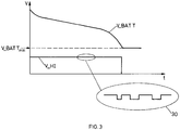
- Figure 3 illustrates schematically as a graph a second embodiment of modulation of V_HI so as to encode the state of charge of battery 15 therein.
- supply voltage V_HI is maintained substantially constant until battery voltage V_BATT reaches the level V_BATT min at which battery voltage V_BATT is insufficient to maintain the operation of the function module 11, and supply voltage V_HI drops substantially to ground potential.
- supply voltage V_HI is modulated with a relatively small-amplitude digital signal superimposed on the DC component of supply voltage V_HI.
- the amplitude of this digital signal is insufficient to affect the operation of the function module, but can be demodulated and decoded by the function module circuitry 12 so as to extract the signal encoded therein by the control unit 17, and thereby to determine the state of charge of battery 15.
- the amplitude of the digital signal may be 100 mV, 50 mV or 10 mV, or any intermediate or lower value as appropriate.
- both a conventional DC/DC converter and a LDO controller are appropriate.
- the control unit 17 may encode the state of charge of battery 15 into the digital signal in any convenient manner, such as simple binary data, e.g. merely reflecting the battery voltage V_BATT, may be encoded in ASCII or a similar protocol, or may be encoded as a pulse-width modulated signal.
- the state of charge of battery 15 may be encoded e.g. as the voltage level e.g. expressed in millivolts, or the level may be divided into blocks and encoded as signals reflecting e.g. "Full charge”, "3/4 full”, “1/2 full”, “1/4 full”, or other suitable divisions. Implementation of such coding strategies, and corresponding decoding, are known to the skilled person and need not be described further.
- the function module circuitry 12 can thus determine the state of charge of rechargeable battery 15.
Description
- The present invention relates to power supplies for portable hearing devices.
- Traditionally, hearing devices were powered by primary cells such as zinc-air batteries, directly connected to the circuitry of the hearing device. Since the circuitry of such a hearing device is directly connected to the battery, the state of charge of the battery can be directly measured by the hearing device circuitry by measuring the voltage produced by the battery, and the user can be informed of the state of charge of the battery and be alerted once the voltage, and thus the state of charge, drops below a predefined level, indicating that the battery should be replaced. Replacing the battery frequently is expensive and can be difficult for persons with physical limitations.
- More recently, rechargeable batteries have found use in hearing devices. Rechargeable batteries, also known as secondary cells, eliminate the requirement for frequent battery replacement, since they can be recharged, e.g. either by connecting the hearing device to a suitable external power supply, or by wireless transmission of power. This simplifies usage of the hearing device for the user. However, unlike primary cells, secondary cells can generate relatively high voltage levels, e.g. greater than 1.5 V, which can damage or destroy the sensitive circuitry of the hearing device. In consequence, a battery power management system is often used to control charging of the battery and also to ensure constant voltage levels of the power supplied to the circuitry such that this voltage level does not exceed a threshold which may damage this circuitry. However, since the battery power management system ensures a constant voltage to the circuitry of the hearing device, this can no longer measure the state of charge of the battery by directly monitoring its output voltage, since it is no longer directly connected thereto. It is thus possible that the user may be surprised by sudden powering down of the hearing device without warning due to the battery being exhausted.
-
WO 00/79836 A1 EP 2 672 731 A1 discloses a hearing instrument system with an accumulator. The accumulator provides energy to the hearing instrument and transmits state of charge information generated by an accumulator control facility to the hearing instrument by way of a respective communication link. The transmission of the state of charge information enables a reliable state of charge detection in the case of batteries, whose state of charge cannot be identified based on their voltage. - The object of the present invention is thus to at least partially overcome one or more of the above-mentioned disadvantages.
- Under the term "hearing devices" we understand hearing aids for the hard-of-hearing, communication devices such as earpieces for radios or music listening, active hearing protection for loud noises, and so on. Such hearing devices may be situated at least partially in the wearer's ear canal, and/or may comprise a unit situated behind the wearer's pinna. In the present specification, the term "hearing device" relates to the entire device, comprising battery, power management circuitry, and the term "function module" refers to the conventional hearing device components and circuitry such as signal processing circuitry, a receiver, microphone and/or reception coil, and so on.
- The object of the invention is attained by a hearing device according to the independent device claim. This hearing device comprises a function module as defined above. The hearing device further comprises a rechargeable battery and a battery power management unit. The battery power management unit comprises a voltage regulator in operative connection with the rechargeable battery for regulating and supplying a supply voltage to the function module. Furthermore, the battery power management unit comprises a control unit in operative connection with the voltage regulator and the rechargeable battery. The control unit is arranged to measure the output voltage of the rechargeable battery and also to control the supply voltage output by the voltage regulator. The control unit controls the voltage regulator so as to encode a signal dependent on the rechargeable battery output voltage onto the supply voltage. In consequence, the function module is provided with information relating to the voltage of the rechargeable battery, and hence the state of charge of the rechargeable battery, and thus can decode this information and inform the user of the hearing device appropriately, such as by giving a signal when the rechargeable battery requires recharging.
- In an embodiment of the hearing device, the voltage regulator is a DC/DC converter or a Low Dropout Regulator, both of which are simple and efficient variants of voltage regulators suitable for use in the hearing device of the invention.
- In an embodiment of the hearing device, the control unit is further adapted to charge the rechargeable battery when an external source of power is supplied to the hearing device, e.g. wirelessly via an induction coil or via a cable. The control unit thus can, in one unit, control all power management within the power management unit.
- In an embodiment of the hearing device, the control unit is arranged to encode the signal relating to the battery voltage digitally onto the supply voltage. This digital encoding may be e.g. a pulse width modulated signal or a binary signal eg. with ASCII encoding. This permits supplying a substantially constant voltage to the function module, with the signal being encoded in a relatively small-amplitude digital signal superimposed thereupon. The amplitude of the digital signal may be less than 100 mV, particular less than 50 mV, further particularly substantially 10 mV.
- In an alternative embodiment of the hearing device, the control unit is adapted to encode the signal relating to the battery voltage in an analogue manner on to the supply voltage. This provides a particularly simple solution, since this can be achieved with simple analogue circuitry. The signal superimposed on the supply voltage can be proportional to the rechargeable battery output voltage. In a specific embodiment, the supply voltage is determined by the equation

- In an embodiment of the hearing device, the function module is adapted to determine the state of charge of the rechargeable battery at least partly based on measurement of the supply voltage and decoding of the signal encoded therein. By "measurement" we understand not only direct analogue measurement of the entire signal itself, but also measurement of the signal superimposed thereupon. In its simplest form for the digital case, this measurement may be merely extracting the digital signal and determining whether the signal is "high" or "low" at any given timepoint, e.g. by using a comparator. The function module can thus decode the information on the state of charge of the rechargeable battery and can then, if desired, provide information relating thereto to the user of the hearing device.
- An object the invention is likewise attained by a method of supplying power to a function module of a hearing device according to the independent method claim. This method comprises supplying power from a rechargeable battery at a rechargeable battery output voltage, and measuring this rechargeable battery output voltage. The rechargeable battery output voltage is regulated to generate a supply voltage, and a signal dependent on the measured rechargeable battery output voltage is encoded on to the supply voltage, e.g. by varying the supply voltage or by modulating a digital or analogue signal on to the supply voltage.
- A state of charge of the rechargeable battery is then determined by decoding said signal.
- In an embodiment of the method, the signal is encoded as a digital signal, which may be a binary signal encoded in a protocol such as ASCII or a pulse width modulated signal. This digital signal may have an amplitude of less than 100 mV, particular less than 50 mV, further particularly substantially 10 mV.
- In an alternative embodiment of the method, the signal is encoded as an analogue signal, which may be proportional to the rechargeable battery output voltage. In a specific embodiment, the supply voltage is determined by the equation

- An object the invention is likewise attained by a method of operating a hearing device corresponding to one of the above-mentioned hearing device embodiments, wherein power is supplied to the function module of the hearing device by one of the above-mentioned method embodiments, the signal relating to the state of charge of the rechargeable battery is decoded by the function module, and the state of charge of the rechargeable battery is determined by the function module based on the decoded signal. In an additional step, the user of the hearing device is informed of the determined state of charge of the rechargeable battery.
- The invention will be described in the following by means of nonlimiting examples illustrated in the figures, which show:
-
Figure 1 : a schematic block diagram of a hearing device according to the invention; -
Figure 2 : a schematic graph illustrating an analogue encoding of the battery voltage onto the supply voltage; and -
Figure 3 : a schematic graph illustrating a digital encoding of the battery voltage of the supply voltage. -
Figure 1 illustrates ahearing device 10 according to the invention in its broadest terms.Hearing device 10 comprises afunction module 11 which, as is conventional, comprisesfunction module circuitry 12 and a receiver (loudspeaker) 13. Thefunction module 11 is conventional, and need not be described further. Electrical power is supplied to thefunction module 11 via itselectrical connections power connection 11+ is provided by batterypower management system 14, and according to current practice is typically approximately 1.2 V, however other voltages are conceivable. Supply voltage V_HI is typically less than or equal to battery voltage V_BATT. Batterypower management system 14 comprises abattery 15 comprising at least one secondary cell such as a lithium-based secondary cell, generating a battery voltage V_BATT.Voltage regulator 16 regulates the battery voltage V_BATT produced bybattery 15 so as to output regulated supply voltage V_HI atoutput 16po.Voltage regulator 16 may be a DC/DC converter, a Low Dropout Regulator (LDO), or any other convenient type of voltage regulator. The level of regulated supply voltage V_HI is determined according to command signals received at voltageregulator command input 16ci. Furthermore, batterypower management system 14 comprises acontrol unit 17, which is described further below. -
Control unit 17 is arranged to receive energy E from an external source at itspower input 17pi as is conventional, either via a wire connection or wirelessly via inductive power transmission, and to direct this received energy via itspower output 17po so as to chargebattery 15 and also to provide power directly tovoltage regulator 16.Control unit 17 is arranged to measure the voltage V_BATT produced bybattery 15 atmeasurement input 17m. Althoughmeasurement input 17m has been illustrated as a separate input, this is merely schematic, and the battery voltage V_BATT produced by thebattery 15 maybe measured at thepower output 17po of thecontrol unit 17. -
Control unit 17, as mentioned above, measures the battery voltage V_BATT produced bybattery 15, and then outputs control signals CS via itscontrol output 17co which are received by voltageregulator control input 16ci. The control signals CS are generated at least partially dependent on the battery voltage V_BATT produced bybattery 15, hence are dependent on the state of charge ofbattery 15. As such, the supply voltage V_HI supplied to thefunction module 11 is varied and/or modulated dependent on the state of charge ofbattery 15 based on the control signals received at voltage regulator control input 16ci: in other words, the state of charge ofbattery 15 is encoded into the supply voltage V_HI supplied to the function module.Function module circuitry 12 measures the supply voltage V_HI supplied to thefunction module 11, and by decoding the signal encoded onto supply voltage V_HI, determines the state of charge ofbattery 15, and can then inform the user accordingly about the state of charge ofbattery 15 as is conventional, e.g. by audio signals, illuminating LEDs or indicating on LCD elements, either on the hearing device itself, or on a remote control for the hearing device or on a smartphone. - The skilled person may arrange the modulation of the supply voltage V_HI supplied to the
function module 11 in any convenient known manner. Several concrete embodiments of this modulation are elaborated below. -
Figure 2 illustrates schematically as a graph a first embodiment of modulation of the supply voltage V_HI supplied to thefunction module 11 so as to encode the state of charge ofbattery 15 therein in an analogue manner. In this embodiment, the supply voltage V_HI is varied by thecontrol unit 17 controlling thevoltage regulator 16 in an analogue fashion such that, as time passes and battery voltage V_BATT drops from its maximum value V_BATTmax, supply voltage V_HI drops from its maximum value V_HImax proportionally to the battery voltage V_BATT, while remaining within a voltage range suitable for operation of the function module. The signal representing the state of charge of therechargeable battery 15 is thus represented by the variation of voltage V_HI. The change dV_BATT in battery voltage V_BATT before the function module becomes inoperable at a battery voltage of V_BATTmin, at which point V_HI drops from V_HImin substantially to ground, is today approximately 1200 mV, and as an example the change dV_HI supply voltage V_HI may be arranged to change by for instance dV_BATT/10, i.e. by approximately 120 mV over the same range of battery voltage V_BATT. Other ratios are of course naturally conceivable, and the proportionality between V_BATT and V_HI does not have to be linear, but may be a step function, or a different nonlinear relationship.Function module circuitry 12 can thus, by measuring supply voltage V_HI, determine the state of charge ofbattery 15 and can thus provide this information to the wearer. In this case, a DC/DC converter would be an appropriate choice forvoltage regulator 16. It should be noted that, although V_HImax has been illustrated as being lower than V_BATTmin, this does not have to be the case: V_HImax may be higher than V_BATTmin. - Mathematically, a specific embodiment of this analog encoding can be expressed for when V_BATT>V_BATTmin as the following equation:

-
Figure 3 illustrates schematically as a graph a second embodiment of modulation of V_HI so as to encode the state of charge ofbattery 15 therein. - In macroscopic terms, in this embodiment supply voltage V_HI is maintained substantially constant until battery voltage V_BATT reaches the level V_BATTmin at which battery voltage V_BATT is insufficient to maintain the operation of the
function module 11, and supply voltage V_HI drops substantially to ground potential. However, viewed at a larger scale as illustrated inbubble 30, supply voltage V_HI is modulated with a relatively small-amplitude digital signal superimposed on the DC component of supply voltage V_HI. The amplitude of this digital signal is insufficient to affect the operation of the function module, but can be demodulated and decoded by thefunction module circuitry 12 so as to extract the signal encoded therein by thecontrol unit 17, and thereby to determine the state of charge ofbattery 15. For example, the amplitude of the digital signal may be 100 mV, 50 mV or 10 mV, or any intermediate or lower value as appropriate. For this embodiment, both a conventional DC/DC converter and a LDO controller are appropriate. - The
control unit 17 may encode the state of charge ofbattery 15 into the digital signal in any convenient manner, such as simple binary data, e.g. merely reflecting the battery voltage V_BATT, may be encoded in ASCII or a similar protocol, or may be encoded as a pulse-width modulated signal. The state of charge ofbattery 15 may be encoded e.g. as the voltage level e.g. expressed in millivolts, or the level may be divided into blocks and encoded as signals reflecting e.g. "Full charge", "3/4 full", "1/2 full", "1/4 full", or other suitable divisions. Implementation of such coding strategies, and corresponding decoding, are known to the skilled person and need not be described further. - By extracting and decoding the digital signal superimposed on V_HI, the
function module circuitry 12 can thus determine the state of charge ofrechargeable battery 15. - Other embodiments of encoding the stated charge of
battery 15 into the supply voltage V_HI include, but are not limited to, amplitude modulation and frequency modulation of sine waves, square waves, triangular waves, sawtooth waves etc. - Although the invention has been described in terms of specific embodiments, these are not to be construed as limiting to the scope of the invention as defined by the appended claims.
Claims (15)
- Hearing device (10) comprising a function module (11), a rechargeable battery (15), and a battery power management unit (14), the battery power management unit (14) comprising:- a voltage regulator (16) in operative connection with the rechargeable battery (15), the voltage regulator (16) being adapted to output a supply voltage (V_HI) to the function module (11);- a control unit (17) in operative connection with the voltage regulator (16) and with the rechargeable battery (15), the control unit (17) being adapted to measure the rechargeable battery output voltage (V_BATT) and to control the supply voltage (V_HI) output by the voltage regulator (16);characterized in that the control unit (17) is adapted to control the voltage regulator (16) so as to encode a signal in dependence of the rechargeable battery output voltage (V_BATT) onto the supply voltage (V_HI); and
wherein the function module (11) is adapted to decode said signal and to determine a state of charge of the rechargeable battery (15) based on said signal. - Hearing device (10) according to claim 1, wherein the voltage regulator (16) is a DC/DC converter or a Low Dropout Regulator.
- Hearing device (10) according to one of claims 1 or 2, wherein the control unit (17) is further adapted to charge the rechargeable battery (15) on application of a source of power (E) external to the hearing device (10).
- Hearing device (10) according to one of claims 1 to 3, wherein the control unit (17) is adapted to encode said signal digitally onto the supply voltage (V_HI).
- Hearing device (10) according to claim 4, wherein said signal is encoded as at least one of:- a pulse width modulated signal;- a binary encoded signal such as an ASCII signal.
- Hearing device (10) according to one of claims 1-3, wherein the control unit (17) is adapted to encode said signal in an analogue manner onto the supply voltage (V_HI).
- Hearing device (10) according to claim 6, wherein the said signal is proportional to the rechargeable battery output voltage (V_BATT), wherein in particular the supply voltage (V_HI) is determined by the equation

- Hearing device (10) according to one of claims 1 to 7, wherein the function module (11) is adapted to determine the state of charge of the rechargeable battery (15) at least partially based on measurement of the supply voltage (V_HI) and decoding of the signal encoded therein.
- Method of supplying power to a function module (11) of a hearing device (10) comprising the steps of:- supplying power from a rechargeable battery (15) at a rechargeable battery output voltage (V_BATT);- a control unit (17) measuring the rechargeable battery output voltage (V_BATT);- a voltage regulator (16) generating a supply voltage (V_HI) under control of the control unit (17) by regulating the rechargeable battery output voltage (V_BATT) and outputting the supply voltage (V_HI) to the function module (11),characterized in- the voltage regulator (16) encoding under control of the control unit (17) a signal in dependence of the measured rechargeable battery supply voltage (V_BATT) onto the supply voltage (V_HI);- the function module (11) decoding said signal; and- the function module (11) determining a state of charge of the rechargeable battery (15) based on said signal.
- Method according to claim 9, wherein said signal is encoded as a digital signal.
- Method according to claim 10, wherein the digital signal is a pulse width modulated signal or a binary encoded signal such as an ASCII signal.
- Method according to claim 9, wherein said signal is encoded as an analogue signal.
- Method according to claim 12, wherein said signal is proportional to the rechargeable battery output voltage, wherein in particular the supply voltage (V_HI) is determined by the equation

- Method of operating a hearing device (10), said hearing device (10) being a hearing device (10) according to one of claims 1-8, comprising the steps of:- supplying power to the function module (11) by the method of one of claims 9-13;- decoding said signal from the measured supply voltage (V_HI);- determining a state of charge of the rechargeable battery (15) based on said decoded signal.
- Method of operating a hearing device according to claim 14, further comprising the step of informing the user of the hearing device (10) of the determined state of charge of the rechargeable battery (15).
Applications Claiming Priority (1)
| Application Number | Priority Date | Filing Date | Title |
|---|---|---|---|
| PCT/EP2013/051606 WO2014117801A1 (en) | 2013-01-29 | 2013-01-29 | State of charge indication in a hearing device |
Publications (2)
| Publication Number | Publication Date |
|---|---|
| EP2952015A1 EP2952015A1 (en) | 2015-12-09 |
| EP2952015B1 true EP2952015B1 (en) | 2019-10-30 |
Family
ID=47633047
Family Applications (1)
| Application Number | Title | Priority Date | Filing Date |
|---|---|---|---|
| EP13702426.1A Active EP2952015B1 (en) | 2013-01-29 | 2013-01-29 | State of charge indication in a hearing device |
Country Status (5)
| Country | Link |
|---|---|
| US (1) | US9621999B2 (en) |
| EP (1) | EP2952015B1 (en) |
| CN (1) | CN105027583B (en) |
| DK (1) | DK2952015T3 (en) |
| WO (1) | WO2014117801A1 (en) |
Families Citing this family (9)
| Publication number | Priority date | Publication date | Assignee | Title |
|---|---|---|---|---|
| CN106463987B (en) | 2014-06-18 | 2019-12-24 | Z动力能源有限责任公司 | Voltage regulator and control circuit for silver-zinc battery in hearing instrument |
| AU2015277299B2 (en) * | 2014-06-18 | 2019-09-19 | Zpower, Llc | Hearing aid battery door module |
| US10204511B2 (en) * | 2016-04-01 | 2019-02-12 | Caavo Inc | Remote control device usage detection based on power consumption |
| US10424955B2 (en) | 2016-10-28 | 2019-09-24 | Starkey Laboratories, Inc. | Charging system with compressible contacts |
| US10491024B2 (en) * | 2016-10-28 | 2019-11-26 | Starkey Laboratories, Inc. | Charging systems for contact chargers and related methods |
| US10701284B2 (en) | 2017-02-10 | 2020-06-30 | Caavo Inc | Determining state signatures for consumer electronic devices coupled to an audio/video switch |
| JP7151572B2 (en) * | 2019-03-19 | 2022-10-12 | コニカミノルタ株式会社 | Ultrasound diagnostic system |
| US11665490B2 (en) | 2021-02-03 | 2023-05-30 | Helen Of Troy Limited | Auditory device cable arrangement |
| US20220394401A1 (en) * | 2021-06-02 | 2022-12-08 | Gn Hearing A/S | Hearing device |
Citations (8)
| Publication number | Priority date | Publication date | Assignee | Title |
|---|---|---|---|---|
| EP0777311A2 (en) | 1995-12-06 | 1997-06-04 | International Computers Limited | Combined data and power transmission |
| WO2000079836A1 (en) | 1999-06-16 | 2000-12-28 | Phonak Ag | Hearing-aid, worn behind the ear and attachment module for a hearing-aid of this type |
| US6310960B1 (en) | 1998-02-23 | 2001-10-30 | Research International, Inc. | Rechargeable hearing aid system |
| EP1727395A2 (en) | 2005-05-25 | 2006-11-29 | Audia Akustik GmbH | Method and apparatus for charging hearing aids inductively |
| WO2007042026A1 (en) | 2005-10-14 | 2007-04-19 | Widex A/S | A method for the use in a battery alarm of a hearing aid, a circuit for monitoring an electric cell, and a hearing aid with such circuit |
| US20090022306A1 (en) | 2007-07-20 | 2009-01-22 | Allen Wang | Encoding Status Signals in DC Voltage Levels |
| US20100098278A1 (en) | 2008-10-17 | 2010-04-22 | Oticon A/S | Listening system comprising a charging station with a data memory |
| EP2672731A1 (en) * | 2012-06-06 | 2013-12-11 | Siemens Medical Instruments Pte. Ltd. | Hearing aid system with rechargeable battery |
Family Cites Families (9)
| Publication number | Priority date | Publication date | Assignee | Title |
|---|---|---|---|---|
| US4396806B2 (en) * | 1980-10-20 | 1998-06-02 | A & L Ventures I | Hearing aid amplifier |
| US5774452A (en) * | 1995-03-14 | 1998-06-30 | Aris Technologies, Inc. | Apparatus and method for encoding and decoding information in audio signals |
| US6498455B2 (en) * | 2001-02-22 | 2002-12-24 | Gary Skuro | Wireless battery charging system for existing hearing aids using a dynamic battery and a charging processor unit |
| US7324652B2 (en) * | 2003-12-30 | 2008-01-29 | Starkey Laboratories, Inc. | Hearing aid having a supply source providing multiple supply voltages |
| JP2007043565A (en) | 2005-08-04 | 2007-02-15 | Fuji Electric Holdings Co Ltd | Signal transmitting method |
| US8225111B2 (en) | 2005-12-19 | 2012-07-17 | Power Integrations, Inc. | Method and apparatus to authenticate a power supply |
| US8150075B2 (en) * | 2008-03-04 | 2012-04-03 | Sonitus Medical, Inc. | Dental bone conduction hearing appliance |
| JP5978286B2 (en) * | 2011-03-22 | 2016-08-24 | アドバンスド エレクトロアコースティックス プライベート リミテッド | Communication device |
| US9227058B2 (en) * | 2012-11-30 | 2016-01-05 | Cochlear Limited | Data/power transfer over a communication link |
-
2013
- 2013-01-29 US US14/763,906 patent/US9621999B2/en active Active
- 2013-01-29 EP EP13702426.1A patent/EP2952015B1/en active Active
- 2013-01-29 DK DK13702426.1T patent/DK2952015T3/en active
- 2013-01-29 WO PCT/EP2013/051606 patent/WO2014117801A1/en active Application Filing
- 2013-01-29 CN CN201380071722.XA patent/CN105027583B/en active Active
Patent Citations (8)
| Publication number | Priority date | Publication date | Assignee | Title |
|---|---|---|---|---|
| EP0777311A2 (en) | 1995-12-06 | 1997-06-04 | International Computers Limited | Combined data and power transmission |
| US6310960B1 (en) | 1998-02-23 | 2001-10-30 | Research International, Inc. | Rechargeable hearing aid system |
| WO2000079836A1 (en) | 1999-06-16 | 2000-12-28 | Phonak Ag | Hearing-aid, worn behind the ear and attachment module for a hearing-aid of this type |
| EP1727395A2 (en) | 2005-05-25 | 2006-11-29 | Audia Akustik GmbH | Method and apparatus for charging hearing aids inductively |
| WO2007042026A1 (en) | 2005-10-14 | 2007-04-19 | Widex A/S | A method for the use in a battery alarm of a hearing aid, a circuit for monitoring an electric cell, and a hearing aid with such circuit |
| US20090022306A1 (en) | 2007-07-20 | 2009-01-22 | Allen Wang | Encoding Status Signals in DC Voltage Levels |
| US20100098278A1 (en) | 2008-10-17 | 2010-04-22 | Oticon A/S | Listening system comprising a charging station with a data memory |
| EP2672731A1 (en) * | 2012-06-06 | 2013-12-11 | Siemens Medical Instruments Pte. Ltd. | Hearing aid system with rechargeable battery |
Also Published As
| Publication number | Publication date |
|---|---|
| EP2952015A1 (en) | 2015-12-09 |
| US20150326982A1 (en) | 2015-11-12 |
| WO2014117801A1 (en) | 2014-08-07 |
| CN105027583A (en) | 2015-11-04 |
| US9621999B2 (en) | 2017-04-11 |
| CN105027583B (en) | 2018-09-07 |
| DK2952015T3 (en) | 2020-02-03 |
Similar Documents
| Publication | Publication Date | Title |
|---|---|---|
| EP2952015B1 (en) | State of charge indication in a hearing device | |
| EP3269020B1 (en) | Method for generating load of wireless power receiver in wireless charging system and wireless power receiver | |
| US8831256B2 (en) | Controlling a link for different load conditions | |
| CN108293167B (en) | Method for charging a battery of a hearing aid and hearing aid with a battery charging unit | |
| EP2546952B1 (en) | Detecting and switching battery polarity in a battery charger | |
| EP3425769B1 (en) | Adapting wireless power transfer parameters to transmitter operating conditions | |
| US20050259838A1 (en) | Hearing aid and hearing aid system | |
| US20240128775A1 (en) | Charging/Discharging Circuit and Electronic Device | |
| US10368166B2 (en) | Voltage regulator and control circuit for silver-zinc batteries in hearing instruments | |
| US11196303B2 (en) | Control device, power receiving device, electronic apparatus, and contactless power transmission system | |
| US9820061B2 (en) | Controlling a link for different load conditions | |
| CN106856584B (en) | Hearing aid with power management | |
| WO2014034523A1 (en) | Contactless charging system | |
| EP1455256A3 (en) | Universal battery | |
| DE60306181D1 (en) | METHOD FOR POWER MANAGEMENT IN A BATTERY-OPERATED DEVICE AND BATTERY-OPERATED ENTRY | |
| JP2015053754A (en) | Non-contact charging system and secondary battery pack | |
| JP2015144519A (en) | Information processing device, and processing method in information processing device | |
| KR20150052516A (en) | Hearing device using multiple battery and method to manage power of the hearing device | |
| WO2018036638A1 (en) | Hearing device and hearing system as well as method for operating a hearing device | |
| CN105789720A (en) | Charging method and device | |
| EP4187925A1 (en) | Hearing device | |
| CN114731480A (en) | Method for operating a hearing aid with a rechargeable battery | |
| EP2568601A1 (en) | AGC with double slope | |
| JP6174952B2 (en) | Charging module and secondary battery pack | |
| JP2022095553A (en) | Hearing device and related wireless charging method |
Legal Events
| Date | Code | Title | Description |
|---|---|---|---|
| PUAI | Public reference made under article 153(3) epc to a published international application that has entered the european phase |
Free format text: ORIGINAL CODE: 0009012 |
|
| 17P | Request for examination filed |
Effective date: 20150729 |
|
| AK | Designated contracting states |
Kind code of ref document: A1 Designated state(s): AL AT BE BG CH CY CZ DE DK EE ES FI FR GB GR HR HU IE IS IT LI LT LU LV MC MK MT NL NO PL PT RO RS SE SI SK SM TR |
|
| AX | Request for extension of the european patent |
Extension state: BA ME |
|
| DAX | Request for extension of the european patent (deleted) | ||
| STAA | Information on the status of an ep patent application or granted ep patent |
Free format text: STATUS: EXAMINATION IS IN PROGRESS |
|
| 17Q | First examination report despatched |
Effective date: 20180621 |
|
| GRAP | Despatch of communication of intention to grant a patent |
Free format text: ORIGINAL CODE: EPIDOSNIGR1 |
|
| STAA | Information on the status of an ep patent application or granted ep patent |
Free format text: STATUS: GRANT OF PATENT IS INTENDED |
|
| RIC1 | Information provided on ipc code assigned before grant |
Ipc: H02J 7/00 20060101ALN20190522BHEP Ipc: H04R 25/00 20060101AFI20190522BHEP |
|
| INTG | Intention to grant announced |
Effective date: 20190614 |
|
| GRAS | Grant fee paid |
Free format text: ORIGINAL CODE: EPIDOSNIGR3 |
|
| GRAA | (expected) grant |
Free format text: ORIGINAL CODE: 0009210 |
|
| STAA | Information on the status of an ep patent application or granted ep patent |
Free format text: STATUS: THE PATENT HAS BEEN GRANTED |
|
| AK | Designated contracting states |
Kind code of ref document: B1 Designated state(s): AL AT BE BG CH CY CZ DE DK EE ES FI FR GB GR HR HU IE IS IT LI LT LU LV MC MK MT NL NO PL PT RO RS SE SI SK SM TR |
|
| REG | Reference to a national code |
Ref country code: GB Ref legal event code: FG4D |
|
| REG | Reference to a national code |
Ref country code: CH Ref legal event code: EP |
|
| REG | Reference to a national code |
Ref country code: AT Ref legal event code: REF Ref document number: 1197406 Country of ref document: AT Kind code of ref document: T Effective date: 20191115 |
|
| REG | Reference to a national code |
Ref country code: DE Ref legal event code: R096 Ref document number: 602013062209 Country of ref document: DE |
|
| REG | Reference to a national code |
Ref country code: IE Ref legal event code: FG4D |
|
| REG | Reference to a national code |
Ref country code: DK Ref legal event code: T3 Effective date: 20200130 |
|
| REG | Reference to a national code |
Ref country code: LT Ref legal event code: MG4D |
|
| PG25 | Lapsed in a contracting state [announced via postgrant information from national office to epo] |
Ref country code: PT Free format text: LAPSE BECAUSE OF FAILURE TO SUBMIT A TRANSLATION OF THE DESCRIPTION OR TO PAY THE FEE WITHIN THE PRESCRIBED TIME-LIMIT Effective date: 20200302 Ref country code: GR Free format text: LAPSE BECAUSE OF FAILURE TO SUBMIT A TRANSLATION OF THE DESCRIPTION OR TO PAY THE FEE WITHIN THE PRESCRIBED TIME-LIMIT Effective date: 20200131 Ref country code: LT Free format text: LAPSE BECAUSE OF FAILURE TO SUBMIT A TRANSLATION OF THE DESCRIPTION OR TO PAY THE FEE WITHIN THE PRESCRIBED TIME-LIMIT Effective date: 20191030 Ref country code: ES Free format text: LAPSE BECAUSE OF FAILURE TO SUBMIT A TRANSLATION OF THE DESCRIPTION OR TO PAY THE FEE WITHIN THE PRESCRIBED TIME-LIMIT Effective date: 20191030 Ref country code: PL Free format text: LAPSE BECAUSE OF FAILURE TO SUBMIT A TRANSLATION OF THE DESCRIPTION OR TO PAY THE FEE WITHIN THE PRESCRIBED TIME-LIMIT Effective date: 20191030 Ref country code: NL Free format text: LAPSE BECAUSE OF FAILURE TO SUBMIT A TRANSLATION OF THE DESCRIPTION OR TO PAY THE FEE WITHIN THE PRESCRIBED TIME-LIMIT Effective date: 20191030 Ref country code: SE Free format text: LAPSE BECAUSE OF FAILURE TO SUBMIT A TRANSLATION OF THE DESCRIPTION OR TO PAY THE FEE WITHIN THE PRESCRIBED TIME-LIMIT Effective date: 20191030 Ref country code: NO Free format text: LAPSE BECAUSE OF FAILURE TO SUBMIT A TRANSLATION OF THE DESCRIPTION OR TO PAY THE FEE WITHIN THE PRESCRIBED TIME-LIMIT Effective date: 20200130 Ref country code: LV Free format text: LAPSE BECAUSE OF FAILURE TO SUBMIT A TRANSLATION OF THE DESCRIPTION OR TO PAY THE FEE WITHIN THE PRESCRIBED TIME-LIMIT Effective date: 20191030 Ref country code: BG Free format text: LAPSE BECAUSE OF FAILURE TO SUBMIT A TRANSLATION OF THE DESCRIPTION OR TO PAY THE FEE WITHIN THE PRESCRIBED TIME-LIMIT Effective date: 20200130 Ref country code: FI Free format text: LAPSE BECAUSE OF FAILURE TO SUBMIT A TRANSLATION OF THE DESCRIPTION OR TO PAY THE FEE WITHIN THE PRESCRIBED TIME-LIMIT Effective date: 20191030 |
|
| REG | Reference to a national code |
Ref country code: NL Ref legal event code: MP Effective date: 20191030 |
|
| PG25 | Lapsed in a contracting state [announced via postgrant information from national office to epo] |
Ref country code: RS Free format text: LAPSE BECAUSE OF FAILURE TO SUBMIT A TRANSLATION OF THE DESCRIPTION OR TO PAY THE FEE WITHIN THE PRESCRIBED TIME-LIMIT Effective date: 20191030 Ref country code: IS Free format text: LAPSE BECAUSE OF FAILURE TO SUBMIT A TRANSLATION OF THE DESCRIPTION OR TO PAY THE FEE WITHIN THE PRESCRIBED TIME-LIMIT Effective date: 20200229 Ref country code: HR Free format text: LAPSE BECAUSE OF FAILURE TO SUBMIT A TRANSLATION OF THE DESCRIPTION OR TO PAY THE FEE WITHIN THE PRESCRIBED TIME-LIMIT Effective date: 20191030 |
|
| PG25 | Lapsed in a contracting state [announced via postgrant information from national office to epo] |
Ref country code: AL Free format text: LAPSE BECAUSE OF FAILURE TO SUBMIT A TRANSLATION OF THE DESCRIPTION OR TO PAY THE FEE WITHIN THE PRESCRIBED TIME-LIMIT Effective date: 20191030 |
|
| REG | Reference to a national code |
Ref country code: DE Ref legal event code: R026 Ref document number: 602013062209 Country of ref document: DE |
|
| PG25 | Lapsed in a contracting state [announced via postgrant information from national office to epo] |
Ref country code: EE Free format text: LAPSE BECAUSE OF FAILURE TO SUBMIT A TRANSLATION OF THE DESCRIPTION OR TO PAY THE FEE WITHIN THE PRESCRIBED TIME-LIMIT Effective date: 20191030 Ref country code: CZ Free format text: LAPSE BECAUSE OF FAILURE TO SUBMIT A TRANSLATION OF THE DESCRIPTION OR TO PAY THE FEE WITHIN THE PRESCRIBED TIME-LIMIT Effective date: 20191030 Ref country code: RO Free format text: LAPSE BECAUSE OF FAILURE TO SUBMIT A TRANSLATION OF THE DESCRIPTION OR TO PAY THE FEE WITHIN THE PRESCRIBED TIME-LIMIT Effective date: 20191030 |
|
| PLBI | Opposition filed |
Free format text: ORIGINAL CODE: 0009260 |
|
| PLAX | Notice of opposition and request to file observation + time limit sent |
Free format text: ORIGINAL CODE: EPIDOSNOBS2 |
|
| REG | Reference to a national code |
Ref country code: AT Ref legal event code: MK05 Ref document number: 1197406 Country of ref document: AT Kind code of ref document: T Effective date: 20191030 |
|
| PG25 | Lapsed in a contracting state [announced via postgrant information from national office to epo] |
Ref country code: SM Free format text: LAPSE BECAUSE OF FAILURE TO SUBMIT A TRANSLATION OF THE DESCRIPTION OR TO PAY THE FEE WITHIN THE PRESCRIBED TIME-LIMIT Effective date: 20191030 Ref country code: MC Free format text: LAPSE BECAUSE OF FAILURE TO SUBMIT A TRANSLATION OF THE DESCRIPTION OR TO PAY THE FEE WITHIN THE PRESCRIBED TIME-LIMIT Effective date: 20191030 Ref country code: SK Free format text: LAPSE BECAUSE OF FAILURE TO SUBMIT A TRANSLATION OF THE DESCRIPTION OR TO PAY THE FEE WITHIN THE PRESCRIBED TIME-LIMIT Effective date: 20191030 Ref country code: IT Free format text: LAPSE BECAUSE OF FAILURE TO SUBMIT A TRANSLATION OF THE DESCRIPTION OR TO PAY THE FEE WITHIN THE PRESCRIBED TIME-LIMIT Effective date: 20191030 |
|
| REG | Reference to a national code |
Ref country code: CH Ref legal event code: PL |
|
| 26 | Opposition filed |
Opponent name: OTICON A/S Effective date: 20200729 |
|
| REG | Reference to a national code |
Ref country code: BE Ref legal event code: MM Effective date: 20200131 |
|
| PG25 | Lapsed in a contracting state [announced via postgrant information from national office to epo] |
Ref country code: LU Free format text: LAPSE BECAUSE OF NON-PAYMENT OF DUE FEES Effective date: 20200129 |
|
| PG25 | Lapsed in a contracting state [announced via postgrant information from national office to epo] |
Ref country code: CH Free format text: LAPSE BECAUSE OF NON-PAYMENT OF DUE FEES Effective date: 20200131 Ref country code: BE Free format text: LAPSE BECAUSE OF NON-PAYMENT OF DUE FEES Effective date: 20200131 Ref country code: SI Free format text: LAPSE BECAUSE OF FAILURE TO SUBMIT A TRANSLATION OF THE DESCRIPTION OR TO PAY THE FEE WITHIN THE PRESCRIBED TIME-LIMIT Effective date: 20191030 Ref country code: LI Free format text: LAPSE BECAUSE OF NON-PAYMENT OF DUE FEES Effective date: 20200131 Ref country code: AT Free format text: LAPSE BECAUSE OF FAILURE TO SUBMIT A TRANSLATION OF THE DESCRIPTION OR TO PAY THE FEE WITHIN THE PRESCRIBED TIME-LIMIT Effective date: 20191030 |
|
| PLBB | Reply of patent proprietor to notice(s) of opposition received |
Free format text: ORIGINAL CODE: EPIDOSNOBS3 |
|
| PG25 | Lapsed in a contracting state [announced via postgrant information from national office to epo] |
Ref country code: IE Free format text: LAPSE BECAUSE OF NON-PAYMENT OF DUE FEES Effective date: 20200129 |
|
| PLCK | Communication despatched that opposition was rejected |
Free format text: ORIGINAL CODE: EPIDOSNREJ1 |
|
| APBM | Appeal reference recorded |
Free format text: ORIGINAL CODE: EPIDOSNREFNO |
|
| APBP | Date of receipt of notice of appeal recorded |
Free format text: ORIGINAL CODE: EPIDOSNNOA2O |
|
| APAH | Appeal reference modified |
Free format text: ORIGINAL CODE: EPIDOSCREFNO |
|
| APBQ | Date of receipt of statement of grounds of appeal recorded |
Free format text: ORIGINAL CODE: EPIDOSNNOA3O |
|
| PG25 | Lapsed in a contracting state [announced via postgrant information from national office to epo] |
Ref country code: TR Free format text: LAPSE BECAUSE OF FAILURE TO SUBMIT A TRANSLATION OF THE DESCRIPTION OR TO PAY THE FEE WITHIN THE PRESCRIBED TIME-LIMIT Effective date: 20191030 Ref country code: MT Free format text: LAPSE BECAUSE OF FAILURE TO SUBMIT A TRANSLATION OF THE DESCRIPTION OR TO PAY THE FEE WITHIN THE PRESCRIBED TIME-LIMIT Effective date: 20191030 Ref country code: CY Free format text: LAPSE BECAUSE OF FAILURE TO SUBMIT A TRANSLATION OF THE DESCRIPTION OR TO PAY THE FEE WITHIN THE PRESCRIBED TIME-LIMIT Effective date: 20191030 |
|
| PG25 | Lapsed in a contracting state [announced via postgrant information from national office to epo] |
Ref country code: MK Free format text: LAPSE BECAUSE OF FAILURE TO SUBMIT A TRANSLATION OF THE DESCRIPTION OR TO PAY THE FEE WITHIN THE PRESCRIBED TIME-LIMIT Effective date: 20191030 |
|
| PGFP | Annual fee paid to national office [announced via postgrant information from national office to epo] |
Ref country code: FR Payment date: 20230125 Year of fee payment: 11 Ref country code: DK Payment date: 20230127 Year of fee payment: 11 |
|
| P01 | Opt-out of the competence of the unified patent court (upc) registered |
Effective date: 20230530 |
|
| APAH | Appeal reference modified |
Free format text: ORIGINAL CODE: EPIDOSCREFNO |
|
| PGFP | Annual fee paid to national office [announced via postgrant information from national office to epo] |
Ref country code: DE Payment date: 20240129 Year of fee payment: 12 Ref country code: GB Payment date: 20240129 Year of fee payment: 12 |