EP2941363B2 - Supplying electric traction motors of a rail vehicle with electrical energy using a plurality of internal combustion engines - Google Patents
Supplying electric traction motors of a rail vehicle with electrical energy using a plurality of internal combustion engines Download PDFInfo
- Publication number
- EP2941363B2 EP2941363B2 EP14700139.0A EP14700139A EP2941363B2 EP 2941363 B2 EP2941363 B2 EP 2941363B2 EP 14700139 A EP14700139 A EP 14700139A EP 2941363 B2 EP2941363 B2 EP 2941363B2
- Authority
- EP
- European Patent Office
- Prior art keywords
- electrical
- machine
- internal combustion
- rectifier
- power converter
- Prior art date
- Legal status (The legal status is an assumption and is not a legal conclusion. Google has not performed a legal analysis and makes no representation as to the accuracy of the status listed.)
- Active
Links
- 238000002485 combustion reaction Methods 0.000 title claims description 97
- 238000000034 method Methods 0.000 claims description 25
- 238000004146 energy storage Methods 0.000 description 24
- 239000000446 fuel Substances 0.000 description 6
- 230000003137 locomotive effect Effects 0.000 description 5
- 239000003990 capacitor Substances 0.000 description 2
- 238000012983 electrochemical energy storage Methods 0.000 description 2
- 238000009499 grossing Methods 0.000 description 2
- 238000012986 modification Methods 0.000 description 2
- 230000004048 modification Effects 0.000 description 2
- 230000001133 acceleration Effects 0.000 description 1
- 230000003213 activating effect Effects 0.000 description 1
- 238000004378 air conditioning Methods 0.000 description 1
- 230000000903 blocking effect Effects 0.000 description 1
- 238000010276 construction Methods 0.000 description 1
- 238000001816 cooling Methods 0.000 description 1
- 238000005516 engineering process Methods 0.000 description 1
- 238000010438 heat treatment Methods 0.000 description 1
- 238000009434 installation Methods 0.000 description 1
- 238000004519 manufacturing process Methods 0.000 description 1
- 230000001172 regenerating effect Effects 0.000 description 1
- 230000001360 synchronised effect Effects 0.000 description 1
Images

Classifications
-
- B—PERFORMING OPERATIONS; TRANSPORTING
- B60—VEHICLES IN GENERAL
- B60L—PROPULSION OF ELECTRICALLY-PROPELLED VEHICLES; SUPPLYING ELECTRIC POWER FOR AUXILIARY EQUIPMENT OF ELECTRICALLY-PROPELLED VEHICLES; ELECTRODYNAMIC BRAKE SYSTEMS FOR VEHICLES IN GENERAL; MAGNETIC SUSPENSION OR LEVITATION FOR VEHICLES; MONITORING OPERATING VARIABLES OF ELECTRICALLY-PROPELLED VEHICLES; ELECTRIC SAFETY DEVICES FOR ELECTRICALLY-PROPELLED VEHICLES
- B60L3/00—Electric devices on electrically-propelled vehicles for safety purposes; Monitoring operating variables, e.g. speed, deceleration or energy consumption
- B60L3/0092—Electric devices on electrically-propelled vehicles for safety purposes; Monitoring operating variables, e.g. speed, deceleration or energy consumption with use of redundant elements for safety purposes
-
- B—PERFORMING OPERATIONS; TRANSPORTING
- B60—VEHICLES IN GENERAL
- B60L—PROPULSION OF ELECTRICALLY-PROPELLED VEHICLES; SUPPLYING ELECTRIC POWER FOR AUXILIARY EQUIPMENT OF ELECTRICALLY-PROPELLED VEHICLES; ELECTRODYNAMIC BRAKE SYSTEMS FOR VEHICLES IN GENERAL; MAGNETIC SUSPENSION OR LEVITATION FOR VEHICLES; MONITORING OPERATING VARIABLES OF ELECTRICALLY-PROPELLED VEHICLES; ELECTRIC SAFETY DEVICES FOR ELECTRICALLY-PROPELLED VEHICLES
- B60L50/00—Electric propulsion with power supplied within the vehicle
- B60L50/10—Electric propulsion with power supplied within the vehicle using propulsion power supplied by engine-driven generators, e.g. generators driven by combustion engines
- B60L50/13—Electric propulsion with power supplied within the vehicle using propulsion power supplied by engine-driven generators, e.g. generators driven by combustion engines using AC generators and AC motors
-
- B—PERFORMING OPERATIONS; TRANSPORTING
- B60—VEHICLES IN GENERAL
- B60L—PROPULSION OF ELECTRICALLY-PROPELLED VEHICLES; SUPPLYING ELECTRIC POWER FOR AUXILIARY EQUIPMENT OF ELECTRICALLY-PROPELLED VEHICLES; ELECTRODYNAMIC BRAKE SYSTEMS FOR VEHICLES IN GENERAL; MAGNETIC SUSPENSION OR LEVITATION FOR VEHICLES; MONITORING OPERATING VARIABLES OF ELECTRICALLY-PROPELLED VEHICLES; ELECTRIC SAFETY DEVICES FOR ELECTRICALLY-PROPELLED VEHICLES
- B60L15/00—Methods, circuits, or devices for controlling the traction-motor speed of electrically-propelled vehicles
- B60L15/007—Physical arrangements or structures of drive train converters specially adapted for the propulsion motors of electric vehicles
-
- B—PERFORMING OPERATIONS; TRANSPORTING
- B60—VEHICLES IN GENERAL
- B60K—ARRANGEMENT OR MOUNTING OF PROPULSION UNITS OR OF TRANSMISSIONS IN VEHICLES; ARRANGEMENT OR MOUNTING OF PLURAL DIVERSE PRIME-MOVERS IN VEHICLES; AUXILIARY DRIVES FOR VEHICLES; INSTRUMENTATION OR DASHBOARDS FOR VEHICLES; ARRANGEMENTS IN CONNECTION WITH COOLING, AIR INTAKE, GAS EXHAUST OR FUEL SUPPLY OF PROPULSION UNITS IN VEHICLES
- B60K5/00—Arrangement or mounting of internal-combustion or jet-propulsion units
- B60K5/08—Arrangement or mounting of internal-combustion or jet-propulsion units comprising more than one engine
-
- B—PERFORMING OPERATIONS; TRANSPORTING
- B60—VEHICLES IN GENERAL
- B60L—PROPULSION OF ELECTRICALLY-PROPELLED VEHICLES; SUPPLYING ELECTRIC POWER FOR AUXILIARY EQUIPMENT OF ELECTRICALLY-PROPELLED VEHICLES; ELECTRODYNAMIC BRAKE SYSTEMS FOR VEHICLES IN GENERAL; MAGNETIC SUSPENSION OR LEVITATION FOR VEHICLES; MONITORING OPERATING VARIABLES OF ELECTRICALLY-PROPELLED VEHICLES; ELECTRIC SAFETY DEVICES FOR ELECTRICALLY-PROPELLED VEHICLES
- B60L2200/00—Type of vehicles
- B60L2200/26—Rail vehicles
-
- B—PERFORMING OPERATIONS; TRANSPORTING
- B60—VEHICLES IN GENERAL
- B60L—PROPULSION OF ELECTRICALLY-PROPELLED VEHICLES; SUPPLYING ELECTRIC POWER FOR AUXILIARY EQUIPMENT OF ELECTRICALLY-PROPELLED VEHICLES; ELECTRODYNAMIC BRAKE SYSTEMS FOR VEHICLES IN GENERAL; MAGNETIC SUSPENSION OR LEVITATION FOR VEHICLES; MONITORING OPERATING VARIABLES OF ELECTRICALLY-PROPELLED VEHICLES; ELECTRIC SAFETY DEVICES FOR ELECTRICALLY-PROPELLED VEHICLES
- B60L2210/00—Converter types
- B60L2210/30—AC to DC converters
-
- B—PERFORMING OPERATIONS; TRANSPORTING
- B60—VEHICLES IN GENERAL
- B60L—PROPULSION OF ELECTRICALLY-PROPELLED VEHICLES; SUPPLYING ELECTRIC POWER FOR AUXILIARY EQUIPMENT OF ELECTRICALLY-PROPELLED VEHICLES; ELECTRODYNAMIC BRAKE SYSTEMS FOR VEHICLES IN GENERAL; MAGNETIC SUSPENSION OR LEVITATION FOR VEHICLES; MONITORING OPERATING VARIABLES OF ELECTRICALLY-PROPELLED VEHICLES; ELECTRIC SAFETY DEVICES FOR ELECTRICALLY-PROPELLED VEHICLES
- B60L2210/00—Converter types
- B60L2210/40—DC to AC converters
-
- B—PERFORMING OPERATIONS; TRANSPORTING
- B60—VEHICLES IN GENERAL
- B60L—PROPULSION OF ELECTRICALLY-PROPELLED VEHICLES; SUPPLYING ELECTRIC POWER FOR AUXILIARY EQUIPMENT OF ELECTRICALLY-PROPELLED VEHICLES; ELECTRODYNAMIC BRAKE SYSTEMS FOR VEHICLES IN GENERAL; MAGNETIC SUSPENSION OR LEVITATION FOR VEHICLES; MONITORING OPERATING VARIABLES OF ELECTRICALLY-PROPELLED VEHICLES; ELECTRIC SAFETY DEVICES FOR ELECTRICALLY-PROPELLED VEHICLES
- B60L2220/00—Electrical machine types; Structures or applications thereof
- B60L2220/40—Electrical machine applications
- B60L2220/42—Electrical machine applications with use of more than one motor
-
- H—ELECTRICITY
- H02—GENERATION; CONVERSION OR DISTRIBUTION OF ELECTRIC POWER
- H02J—CIRCUIT ARRANGEMENTS OR SYSTEMS FOR SUPPLYING OR DISTRIBUTING ELECTRIC POWER; SYSTEMS FOR STORING ELECTRIC ENERGY
- H02J1/00—Circuit arrangements for dc mains or dc distribution networks
- H02J1/10—Parallel operation of dc sources
- H02J1/108—Parallel operation of dc sources using diodes blocking reverse current flow
-
- H—ELECTRICITY
- H02—GENERATION; CONVERSION OR DISTRIBUTION OF ELECTRIC POWER
- H02M—APPARATUS FOR CONVERSION BETWEEN AC AND AC, BETWEEN AC AND DC, OR BETWEEN DC AND DC, AND FOR USE WITH MAINS OR SIMILAR POWER SUPPLY SYSTEMS; CONVERSION OF DC OR AC INPUT POWER INTO SURGE OUTPUT POWER; CONTROL OR REGULATION THEREOF
- H02M1/00—Details of apparatus for conversion
- H02M1/0067—Converter structures employing plural converter units, other than for parallel operation of the units on a single load
- H02M1/008—Plural converter units for generating at two or more independent and non-parallel outputs, e.g. systems with plural point of load switching regulators
-
- Y—GENERAL TAGGING OF NEW TECHNOLOGICAL DEVELOPMENTS; GENERAL TAGGING OF CROSS-SECTIONAL TECHNOLOGIES SPANNING OVER SEVERAL SECTIONS OF THE IPC; TECHNICAL SUBJECTS COVERED BY FORMER USPC CROSS-REFERENCE ART COLLECTIONS [XRACs] AND DIGESTS
- Y02—TECHNOLOGIES OR APPLICATIONS FOR MITIGATION OR ADAPTATION AGAINST CLIMATE CHANGE
- Y02T—CLIMATE CHANGE MITIGATION TECHNOLOGIES RELATED TO TRANSPORTATION
- Y02T10/00—Road transport of goods or passengers
- Y02T10/60—Other road transportation technologies with climate change mitigation effect
- Y02T10/64—Electric machine technologies in electromobility
-
- Y—GENERAL TAGGING OF NEW TECHNOLOGICAL DEVELOPMENTS; GENERAL TAGGING OF CROSS-SECTIONAL TECHNOLOGIES SPANNING OVER SEVERAL SECTIONS OF THE IPC; TECHNICAL SUBJECTS COVERED BY FORMER USPC CROSS-REFERENCE ART COLLECTIONS [XRACs] AND DIGESTS
- Y02—TECHNOLOGIES OR APPLICATIONS FOR MITIGATION OR ADAPTATION AGAINST CLIMATE CHANGE
- Y02T—CLIMATE CHANGE MITIGATION TECHNOLOGIES RELATED TO TRANSPORTATION
- Y02T10/00—Road transport of goods or passengers
- Y02T10/60—Other road transportation technologies with climate change mitigation effect
- Y02T10/70—Energy storage systems for electromobility, e.g. batteries
-
- Y—GENERAL TAGGING OF NEW TECHNOLOGICAL DEVELOPMENTS; GENERAL TAGGING OF CROSS-SECTIONAL TECHNOLOGIES SPANNING OVER SEVERAL SECTIONS OF THE IPC; TECHNICAL SUBJECTS COVERED BY FORMER USPC CROSS-REFERENCE ART COLLECTIONS [XRACs] AND DIGESTS
- Y02—TECHNOLOGIES OR APPLICATIONS FOR MITIGATION OR ADAPTATION AGAINST CLIMATE CHANGE
- Y02T—CLIMATE CHANGE MITIGATION TECHNOLOGIES RELATED TO TRANSPORTATION
- Y02T10/00—Road transport of goods or passengers
- Y02T10/60—Other road transportation technologies with climate change mitigation effect
- Y02T10/7072—Electromobility specific charging systems or methods for batteries, ultracapacitors, supercapacitors or double-layer capacitors
-
- Y—GENERAL TAGGING OF NEW TECHNOLOGICAL DEVELOPMENTS; GENERAL TAGGING OF CROSS-SECTIONAL TECHNOLOGIES SPANNING OVER SEVERAL SECTIONS OF THE IPC; TECHNICAL SUBJECTS COVERED BY FORMER USPC CROSS-REFERENCE ART COLLECTIONS [XRACs] AND DIGESTS
- Y02—TECHNOLOGIES OR APPLICATIONS FOR MITIGATION OR ADAPTATION AGAINST CLIMATE CHANGE
- Y02T—CLIMATE CHANGE MITIGATION TECHNOLOGIES RELATED TO TRANSPORTATION
- Y02T10/00—Road transport of goods or passengers
- Y02T10/60—Other road transportation technologies with climate change mitigation effect
- Y02T10/72—Electric energy management in electromobility
Definitions
- the invention relates to an arrangement for supplying electric traction motors in a rail vehicle with electrical energy, the arrangement having at least two internal combustion engines.
- An associated electrical machine for generating the electrical energy is provided for each of the at least two internal combustion engines, wherein the electrical machine is mechanically coupled to the internal combustion engine so that it is driven by the internal combustion engine when the electrical machine is operating as a generator.
- At least a first and a second internal combustion engine-machine combination are thus formed.
- the at least one electric traction motor of the rail vehicle can be electrically connected to at least one of the electric machines via at least one traction connection.
- the invention further relates to a method for supplying electric traction motors in a rail vehicle with electrical energy, wherein at least two internal combustion engines are each operated in combination with an associated electric machine, so that at least a first and a second internal combustion engine-machine combination are operated.
- a first operating state of the machine at least a first of the electric machines generates alternating current driven by the associated internal combustion engine during generator operation of the respective electric machine, which is used to operate at least one electric traction motor.
- a second one of the electrical machines is supplied with alternating current from a second machine power converter assigned to it and drives the internal combustion engine assigned to it.
- the rail vehicle is, for example, a locomotive.
- the invention is not limited to this. Rather, the rail vehicle can also be a train set, for example.
- the electrical energy generated by the internal combustion engines is available in the rail vehicle not only to supply the at least one traction motor, but also to supply other electrical consumers.
- the other consumers are in particular so-called auxiliary operations, which do not directly generate traction, but may be absolutely necessary for the running of the rail vehicle.
- Auxiliary operations can generally be defined by the fact that they are supplied with electrical energy from the usually existing DC intermediate circuit via their own auxiliary operation inverter or a plurality of their own auxiliary operation inverters.
- the auxiliary operations include, for example, fans and other cooling devices that cool the combustion engines, the traction motors and/or other devices required for driving (e.g. power converters).
- a braking system is required for driving and components of the braking system such as air compressors are therefore auxiliary operations.
- auxiliary operations are a fire extinguishing device of the rail vehicle, electronic devices for controlling the operation of the rail vehicle, battery chargers, heaters required at least temporarily for driving operation, e.g. window heating of the windshield, and / or lighting device in the driver's compartment.
- auxiliary operations can be distinguished from electrical devices that are only available for the comfort of passengers, such as lights in vehicle compartments. Such electrical devices are usually supplied with electrical energy in trains via the so-called train busbar.
- the train busbar is not connected to the DC link via the auxiliary power inverter or one of the auxiliary power inverters, but rather via its own inverter.
- the electrical energy generated by the electrical machines can also be fed into a DC intermediate circuit in the present invention via at least one rectifier (hereinafter: generator rectifier, since alternating current generated by the generator is rectified).
- generator rectifier since alternating current generated by the generator is rectified.
- inverters are connected to the DC intermediate circuit, which in turn generate the alternating current at the desired electrical voltage level or in the desired electrical voltage range that is required for the consumers and systems connected on the alternating voltage side.
- DC-voltage converters can be provided on their DC voltage side and/or transformers on their AC voltage side in order to change the voltage level.
- Other electrical converters can also be connected to the DC link either directly or indirectly.
- auxiliary operations in addition to the auxiliary operations mentioned, other electrical consumers, such as electrical devices such as lighting, air conditioning and information systems that are available for the comfort of passengers, can also be supplied with electrical energy from the DC intermediate circuit, e.g. B. via a different inverter than the auxiliary operations required for driving.
- a plurality of traction motors of the rail vehicle via one or more traction inverters; a train current busbar via an additional converter or directly; Auxiliary operations required for driving via an auxiliary operations inverter.
- further converters can be connected to the intermediate circuit, for example for the purpose of converting unnecessary energy that occurs when Braking of the rail vehicle is fed into the intermediate circuit, in heat.
- An example of such an arrangement is in WO 2009/077184 A1 described.
- a plurality of combustion engine-machine combinations therefore enables part-load operation of the rail vehicle, i.e. operation in which the maximum possible electrical power is not required.
- Part-load operation is therefore understood to mean an operation in which the mechanical power of only part of the internal combustion engines is sufficient to provide the required electrical power.
- part-load operation also has the advantage that the noise pollution in the environment is lower.
- there may be four internal combustion engine-machine combinations with each combination preferably being able to be operated either at idle or at the optimal power point, independently of the other combinations.
- more than two operating modes can be set for each combination, e.g. in addition to the two operating modes mentioned, operation with medium power of the electrical machine operated as a generator.
- Electrical auxiliary operations which are present in addition to the electric traction motors and are supplied with electrical energy from the DC intermediate circuit, include in particular those auxiliary operations which, as mentioned above, are required for the driving operation of the rail vehicle. If the auxiliary power inverter, via which these auxiliary power are electrically connected to the DC link, fails or has to be switched off, driving cannot continue. This applies even though the DC intermediate circuit and the supply of the traction motors from the intermediate circuit may still be functional.
- One, more or all of the engine-engine combinations could be shut down, so that in due course it becomes necessary to start one or more shut-down engine-engine combinations.
- the combustion engine of the combination must be started, which requires appropriate energy.
- at least one internal combustion engine is started with the help of the associated electrical machine, in that the electrical machine drives the internal combustion engine that is mechanically coupled to it.
- the fuel supply to the internal combustion engine can be started, so that the internal combustion engine begins to work under its own power.
- the internal combustion engine has started, although the starting process can continue until the internal combustion engine reaches a speed at which it can be operated permanently without load without stopping and is ready at any time to increase its speed and also work under load.
- This speed is commonly referred to as an idle speed.
- the internal combustion engine drives the electric machine, which, however, does not supply energy to an electrical load or to a small extent. If the speed is increased further, the internal combustion engine increases the power with which the electric machine generates alternating current, so that electrical consumers can be supplied with electrical energy from the electric machine.
- the energy for starting at least one of the internal combustion engines is expediently obtained from an energy storage device of the rail vehicle, in particular an electrical or electrochemical energy storage device, in particular the vehicle battery.
- an energy storage device of the rail vehicle in particular an electrical or electrochemical energy storage device, in particular the vehicle battery.
- the start of several internal combustion engines and the frequent repetition of starting processes after switching off the internal combustion engines places considerable strain on the vehicle's energy storage system.
- the storage capacity of the energy storage can be increased. However, this is associated with additional costs and/or an increase in the weight and construction volume of the energy storage device, whereby the energy storage device can also consist of units distributed throughout the vehicle.
- a machine inverter which is supplied with direct current from the energy storage or the voltage converter in order to supply the electrical machine with alternating current, is designed for a direct voltage of the order of 750 V or 1 kV.
- US 2011/0080040 A1 describes a drive device with diesel engines, each of which supplies rotational energy to a generator in order to generate an alternating current which is supplied to a corresponding rectifier.
- Each rectifier is electrically connected to one of the generators to produce a direct current that is supplied to a DC link.
- Inverters connected to the DC link convert the DC signal on the DC link into alternating current to drive a drive motor.
- a control is connected to the generators.
- WO 2006/020587 A2 describes methods for regenerative braking of a hybrid locomotive.
- the locomotive can have several engines.
- an internal combustion engine-machine combination that has already started or is in operation is used to start at least one further internal combustion engine-machine combination.
- alternating current which is generated by the electrical machine of the first, already operated combination, i.e. is passed from the first electrical machine to the second electrical machine of the not yet started combination in order to operate the second electrical machine and thereby the internal combustion engine of the second to start the combination.
- the same procedure can be followed if a need for the second electrical machine to be supplied with electrical energy arises or exists during the further course of the starting process or during other operation of the second combination.
- This can be the case in particular if the internal combustion engine is to be operated at idle (i.e. at idle speed) with reduced fuel supply or switched off fuel supply.
- this can also be the case if the operation of the second internal combustion engine is disrupted and the second electrical machine therefore drives the second internal combustion engine, for example in order to avoid an undesirable standstill of the second internal combustion engine.
- a machine power converter is assigned to both the first and second electrical machines, the alternating current side of which is electrically connected to the associated electrical machine.
- the machine power converters each have a DC side, with the DC sides of the machine power converters being electrically connected to one another via a DC voltage connection (i.e. line).
- the DC sides of the machine power converters are therefore directly connected to one another, without additional power converters (e.g. voltage converters).
- At least one of the machine power converters and preferably all machine power converters, the DC sides of which are directly connected to one another via the DC voltage line, are connected to an electrical capacitance (e.g. a capacitor or an arrangement of capacitors).
- an electrical capacitance e.g. a capacitor or an arrangement of capacitors.
- One connection of the capacity is connected to the first potential of the DC voltage connection of the machine power converter and the second, opposite connection of the capacity is connected to the second potential of the DC voltage connection of the machine power converter.
- each of the DC voltage sides of the machine power converters is coupled to a capacitance in this way.
- This has the advantage that fluctuations in the direct voltage are compensated for. But even a single capacitance, whose poles are connected to the two potentials of the DC voltage line, leads to a smoothing of DC voltage fluctuations.
- a capacity or the majority of such capacities has the advantage that electrical energy is stored therein as soon as the capacity is charged.
- this has the advantage that a higher power is briefly available for starting or operating at least one of the internal combustion engine-machine combinations.
- the capacity or the plurality of capacities can be charged before, during and/or after the start of the first internal combustion engine-machine combinations and only then can the second internal combustion engine-machine combinations be started.
- the invention has the advantage that the vehicle's energy storage is placed under less strain because it is only needed to start the first combination. In addition, the reliability of the rail vehicle is increased, although a redundant voltage converter for converting the voltage level at the output of the energy storage is not absolutely necessary.
- the electrical machines of the combinations feed electrical energy into a DC intermediate circuit of the vehicle via at least one rectifier.
- the additional machine power converters which are connected to each other via the DC voltage connection, save overall weight and volume.
- the reason for this is that the at least one rectifier between the electrical machines and the DC link is designed for very high power and therefore requires a correspondingly large weight and volume. If the rectifier is also to be operated as an inverter, the weight and volume will increase.
- the additional machine power converters are designed for relatively small electrical powers, particularly in the case of at least one additional electrical capacity. The additional effort for the machine power converters is therefore low.
- At least one electrical switch is provided and optionally several electrical switches are provided, which are controlled, opened and opened by a control arrangement can be closed.
- This makes it possible to electrically isolate at least one of the machine power converters from the other machine power converters (in this case, at least one electrical switch is provided in the DC voltage connection or is provided at the connection of the machine power converter to the DC voltage connection) and/or to disconnect at least one of the machine power converters from the electrical machine assigned to it (in this case the additional electrical switch is arranged in the connection between the AC voltage side of the machine power converter and the electrical machine).
- An electrical switch is provided with which the at least one rectifier or one of the rectifiers (also called generator rectifier) can be separated from the associated electrical machine or machines and/or the DC intermediate circuit.
- an electrical machine is electrically isolated from the DC intermediate circuit while it supplies energy (in particular for starting an internal combustion engine of a different combination) via the DC voltage connection to an electrical machine of a different combination.
- a first of the electrical machines is electrically isolated from the DC intermediate circuit, while it supplies a second of the electrical machines with electrical energy via the DC voltage line.
- the control arrangement is designed such that the first electrical machine is electrically isolated from the DC intermediate circuit by means of an electrical switch, while it supplies the second electrical machine with electrical energy via the DC line.
- at least one electrical machine is supplied via the DC voltage connection without using the DC intermediate circuit.
- the following also refers to a traction connection, via which a traction motor of the rail vehicle is supplied.
- the electric machine supplies energy (in particular for starting an internal combustion engine of a different combination) via the DC connection to an electric machine of a different combination
- it does not supply any traction motor with electrical energy.
- an electrical switch that is open is provided either between the electric machine and the traction connection or between the traction connection and the traction motor.
- a diode is usually referred to as a freewheeling diode.
- the electrical one-way valves are preferably designed so that they can carry the electrical current required to supply other internal combustion engine-machine combinations.
- a method for supplying electric traction motors in a rail vehicle with electrical energy is proposed, which has the features of claim 3.
- Both the previously defined arrangement and the previously defined method allow, in the presence of more than one internal combustion engine-machine combination, not only the supply of one of the machine converters with direct current that has been rectified from alternating current from the electrical machine of another combination. Rather, a majority of the machine converters can also be supplied with direct current, which is rectified at least from alternating current from the electrical machine of another of the combinations. Furthermore, it is also possible to supply one or more machine power converters of one or more other combinations with rectified alternating current from a plurality of electrical machines.
- the DC voltage line (preferably electrically disconnectable via at least one electrical switch) is connected to an electrical connection via which an electrical or electrochemical energy storage device (in particular the vehicle battery) of the vehicle can feed electrical energy into the DC voltage line during operation of the vehicle.
- an electrical or electrochemical energy storage device in particular the vehicle battery
- the DC voltage line can therefore be used in particular to start at least one of the internal combustion engines.
- the energy storage device feeds electrical energy into the DC voltage line and this electrical energy can be used to start the internal combustion engine by the machine converter generating alternating current and using it to operate the electrical machine of the combination.
- the electrical energy from the vehicle's energy storage can be used to charge an electrical capacity whose poles are connected between the potentials of the DC voltage line.
- first operating state refers to the electrical machine of a specific combination or to the combination. This also applies to the term “second operating state”. Other operating states can occur, for example the combustion engine is at a standstill. In the first operating state, the electric machine is driven by the associated internal combustion engine and generates an alternating electrical voltage, due to which an alternating current can flow. In the second operating state, the electric machine drives the associated internal combustion engine while being supplied with alternating current from the associated machine power converter (also called machine inverter). This means that in the case of several internal combustion engine-machine combinations, the different electrical machines or combinations can be in different operating states at the same time.
- machine power converter also called machine inverter
- the machine of the second combination While, for example, the electric machine of the first combination is in the first operating state, the machine of the second combination, for example, is in the second operating state. However, it cannot be ruled out that all electrical machines can be in the same operating state at a certain point in time. If this is the second operating state, energy for operating the electrical machines can be supplied to consumers, in particular via a DC intermediate circuit of the arrangement. This also applies if none or not all of the electrical machines are in the second operating state.
- the energy from the DC intermediate circuit for supplying the electrical machine(s) can, for example, be generated as AC energy by the at least one traction motor during a braking process of the rail vehicle and fed into the DC intermediate circuit via the associated traction inverter.
- the traction connection can in particular be an AC voltage connection on the AC voltage side of a traction inverter or the DC voltage connection of the traction inverter.
- the electrical machines can supply the alternating current they generate to at least one rectifier (generator-rectifier) and the current rectified by the rectifier can be fed into a DC intermediate circuit.
- At least one traction inverter is connected to this DC intermediate circuit in a manner known per se.
- At least one of the machine power converters also forms the generator rectifier.
- this is not in accordance with the patent claims and is not preferred, in particular for the reasons already mentioned above.
- the arrangement therefore has, in addition to the machine power converters, at least one generator rectifier for rectifying alternating currents that are generated by the electrical machines during generator operation of the respective electrical machine, with the at least one generator rectifier on its AC voltage side having at least one of the electric machines is connected and is connected on its DC voltage side to a DC intermediate circuit, via which the electric traction motor can be supplied with electrical energy.
- this corresponds to rectifying, in the first operating state of the electrical machine or the electrical machines, the alternating current generated by at least one generator rectifier, which is present in addition to the machine power converters, and feeding it into a DC intermediate circuit from which the at least one electrical Traction motor is supplied with electrical energy.
- a generator rectifier is connected to the first electrical machine on its AC voltage side and is connected to the DC intermediate circuit on its DC voltage side.
- At least one electrical capacitance which is connected between the electrical potentials of the DC link, can first be charged with electrical energy, and only then can the alternating current generated be fed into the DC link by the at least one generator rectifier.
- the rectifier via which the electrical machine is connected to the DC intermediate circuit, does not feed any direct current into the DC intermediate circuit at the beginning of the starting process. The reason for this is that at the beginning of the starting process, the machine power converter should deliver a high alternating voltage to operate the electrical machine. This would in turn lead to high currents in the DC link and also reduce the power of the machine converter that is available for the starting process.
- control arrangement can have a plurality of control units which are designed to control the power converters and optionally other devices of the supply arrangement.
- control units are in particular for each of the power converters (generator rectifier, machine power converter, auxiliary power inverter, traction inverter), for the combustion engines and optionally for the controllable electrical switches mentioned above.
- the control units are preferably connected to one another and/or to a higher-level control unit in terms of control technology.
- the machine power converters are controlled in particular by the control arrangement mentioned in such a way that they enable at least one of the internal combustion engines to be started and/or driven by the associated electrical machine, the associated electrical machine drawing energy from another electrical machine of one of the combinations.
- the first machine power converter rectifies an alternating current generated by the assigned first electrical machine and supplies this alternating current to the second machine power converter, which inverts it and thus the second electrical machine provided.
- the first machine power converter is preferably not actively controlled, i.e. H.
- the control for switching electronic switches on and off during inverter operation of the machine power converter does not take place and the alternating current is passively rectified, i.e. e.g.
- the electrical one-way valves e.g. diodes
- the electrical one-way valves form a three-phase half-bridge circuit.
- the second machine power converter which inverts the direct current from the first machine power converter, is preferably actively controlled, in particular by switching its electronic switches on and off accordingly.
- At least one electrical capacitance which is connected between the electrical potentials of the DC voltage line, is first charged with electrical energy, and only then is an electrical machine supplied with converted direct current from the DC voltage line and/or from the at least one capacity (i.e. with alternating current). .
- This has the advantage that more energy is available to supply the electrical machine(s) from the DC voltage line and fluctuations in the voltage of the DC voltage line are smoothed out. This is particularly advantageous when starting the first internal combustion engine with energy from the vehicle's energy storage.
- the exemplary embodiment shown has four internal combustion engine-machine combinations 1, 3, the internal combustion engines 1a, 1b, 1c, 1d preferably being diesel engines.
- the electrical machines 3a, 3b, 3c, 3d are, for example, permanent magnet synchronous motors.
- Each of the combinations 1, 3 is connected via a three-phase connection line 4a, 4b, 4c, 4d to a generator-rectifier 5a, 5b, 5c, 5d assigned to the combination 1, 3.
- the three-phase connection line 4 of each of the combinations runs via a controllable three-phase disconnector 14a, 14b, 14c, 14d.
- the three-phase electrical connection between the electrical machine 3 and the generator rectifier 5 can be interrupted controlled by a control unit (not shown), in particular when the electrical machine 3 of the combination 1, 3 is operated as a motor, but also during a starting process Combination 1, 3.
- the rectifiers 5 are connected to the DC intermediate circuit with the lines 8, 10 via connecting lines 33, 34, which are designed as bus lines for all rectifiers 5.
- inverters that are connected to the lines 8, 10, for example at least one traction inverter, one auxiliary power inverter and one inverter for the traction power supply.
- each of the combinations there is an associated machine inverter 23a, 23b; 23c, 23d provided.
- the AC voltage sides of the machine inverters 23 are each connected to the three-phase connection line 4 of the combination via a switch 24a, 24b, 24c, 24d that can be controlled by a control unit (not shown).
- a capacitance CD is connected between the lines 8, 10 of the intermediate circuit in order to compensate for fluctuations in the direct voltage and/or to absorb energy.
- the DC voltage sides of the machine inverters 23 are connected to one another via a DC voltage connection 18.
- the DC voltage connection 18 is shown by individual lines, although it is a two-pole connection. However, it is possible for the DC voltage sides to be connected to one another, for example via a single-wire electrical line and also via vehicle ground. Since several combinations 1, 3 are present, the DC voltage connection 18 is branched.
- another electrical line 28 is connected to the DC voltage connection 18 in particular is designed as two-pole and allows energy to be taken from an electrical energy storage device 19 (eg vehicle battery) via a switch 27 and a voltage converter 26 as well as via an optional circuit breaker 25.
- the operation of at least one of the machine inverters 23 is therefore also possible with energy from the electrical energy storage 19.
- energy is taken from the electrical energy storage 19 to start the first internal combustion engine and used to start at least one combination 1, 3.
- the combination 1a, 3a is first started, then its electrical machine 3a is operated as a generator and the electrical energy generated is fed into the intermediate circuit 8, 10 via the generator rectifier 5b. It is therefore available for the operation of at least one traction motor and optionally other consumers from the intermediate circuit.
- the energy generated by the electric machine 3a can be fed into the DC voltage connection 18 via the associated machine inverter 23a and is available for the start of one or more other combinations 1, 3.
- the voltage converter 26 is also connected via an electrical line to the line 10 at the higher electrical potential of the intermediate circuit, namely via a resistor 29 and a diode 30.
- the line 22 can be separated from the voltage converter 26 by the switch 27.
- the DC intermediate circuit (in particular the capacitance CD) can be precharged via line 22, i.e. a corresponding electrical voltage can be generated between line 10 and line 8. As a result, very high electrical currents are avoided when the generators 3 are switched on by closing the switches 14.
- Fig. 1 Numerous modifications are possible in the arrangement shown. For example, there may be a different number of combinations 1, 3. Alternatively or additionally, several DC intermediate circuits can be provided, from which at least one traction motor is supplied with electrical energy. Alternatively or additionally, modifications can be made to the devices for feeding energy from the energy storage 19 into the DC voltage connection 18, for example at least one further voltage converter can be connected in parallel to the voltage converter 26 shown in FIG or can simultaneously provide electrical energy via one or more voltage converters.
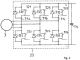
- Fig. 2 shows an exemplary embodiment of a machine power converter or machine inverter, in particular each of the in Fig. 1 machine inverter 23 shown can be. Left in Fig. 2 the associated electrical machine 3 is shown, with the optional electrical switch 24 off Fig. 1 in Fig. 2 is not shown.
- the electrical machine 3 is connected via a three-phase electrical line which is in Fig. 1 is shown as a branch of line 4, connected to the AC voltage side of the machine converter 23.
- the power converter 23 is made up of three half-bridges 31a, 31b, 31c, each of which is formed by a series connection of two parallel connections, each of a controllable electronic switch 321-326 and a diode 331-336 connected in anti-parallel to it.
- the contact of the AC voltage connection between the parallel circuits connected in series is located in each half bridge 31a, 31b, 31c.
- the opposite ends of the half bridges 31 are each routed to one of two common poles of the DC voltage connection, which are in Fig. 2 are marked with a plus sign and a minus sign.
- a capacitance 34 is connected between these poles or different electrical potentials.
- the two poles of the DC voltage connection are connected to a DC voltage connection, via which the power converter 23 can be supplied with direct current and can preferably also supply other devices with direct current, depending on the operating state in which the electrical machine is.
- the control of the electronic valves 321-326 (which are preferably IGBTs) is also carried out or not carried out.
- the inverter operation of the power converter 23 is blocked (in particular, the electronic valves are then all switched off) when the electrical machine 3 cannot be supplied with alternating current from the power converter 23.
- the alternating current is due to the diodes 331-336 of the power converter 23 rectified and, in accordance with the linked alternating voltages of the three phases, a direct current results on the direct voltage side of the converter 23, the voltage fluctuations of which are smoothed out by the capacitance 34.
- the electrical potentials at the respective contacts of the AC voltage connection of the power converter 23 are temporarily greater than the electrical potentials at the positive pole of the DC voltage connection in each period of the alternating current, so that the diodes 331, 333, 335 become correspondingly electrically conductive.
- the electrical potential at the AC voltage contacts is temporarily lower in each period than the electrical potential at the second pole of the DC voltage connection, so that the diodes 332, 334, 336 temporarily become electrically conductive.
- each of the machine power converters 23 a capacitance is connected between the poles of the DC voltage connection, the capacitances preferably being chosen to be the same size.
- the total capacity present in the DC voltage connection of the machine converters is therefore at least as large as the number of connected machine converters multiplied by the individual capacity. Significant energy can therefore be stored in the capacities and is available to supply the machine power converters to one another.
- the smoothing of voltage fluctuations in the DC voltage connection is improved.
- energy is preferably not only drawn from the capacities of the DC voltage connection, but energy is additionally fed into the DC voltage connection from at least one of the other combinations during the starting process.
- the voltage level can be higher due to the supply of electrical energy from at least one of the electrical machines of the combinations in the DC voltage connection than if the DC voltage connection exclusively draws energy from the energy storage 19 of the vehicle.
- the voltage level at the storage-side input of the voltage converter 26 is approximately 110 V and the voltage converter increases this voltage at its output to a voltage level in the range of 750 V.
- this increased voltage level is in particular lower than the later voltage level in the DC voltage connection 18, which can be achieved when energy is fed in via one or more of the machine converters 23.
- Starting processes or other supplies of the various combinations 1, 3 to each other can therefore take place at a higher voltage level and thus faster and with higher energy flows than when supplied exclusively from the vehicle's energy storage. In particular, all existing combinations can therefore be started faster and more effectively than if starting energy is obtained exclusively from the energy storage 19.
- the electrical switches 14 are open and the electrical machines 3 are therefore still electrically isolated from the DC intermediate circuit 8, 10.
- the switch 27 is preferably first closed in order to connect the output of the voltage converter 26 to the DC voltage connections of the machine power converter 23 and at the same time to the DC intermediate circuit 8, 10.
- the blocking diode 30 is located in the electrical line 22 in order to protect against excessive voltage when the intermediate circuit is in operation after the internal combustion engines have started.
- the at least one voltage converter 26 can be switched on and after switching on the optional circuit breaker 25, the energy storage 19 or the voltage converter 26 loads the capacitances CD into the intermediate circuit 8, 10 and not into them Fig. 1 Capacitances shown at the connections of the DC voltage connection 18.
- the capacity CD By charging the capacity CD, the arrangement is protected from excessive currents that could occur without precharging the capacity after at least one of the switches 14 is switched on.
- the direct voltage at the output of the voltage converter 26 can initially be low and then increased over time.
- the starting process of a first internal combustion engine begins.
- the switch 25 in the electrical line between the machine power converter 23 of the combination is closed and the machine power converter 23 is controlled so that an alternating voltage is generated on its AC voltage side and an alternating current flows to the associated electrical machine 3.
- the control of the internal combustion engine can be put into a ready-to-start state.
- the machine converter 23 of the combination to be started is controlled in such a way that the alternating current generated by it generates a rotating field in the associated electrical machine 3 in the direction of rotation in which the coupled operation of the internal combustion engine and the electrical machine is to take place.
- the frequency of this alternating current is preferably increased over time in order to first set the internal combustion engine in motion from rest and then accelerate it.
- the internal combustion engine control unit automatically begins supplying fuel to the internal combustion engine, so that the internal combustion engine itself contributes to further acceleration.
- the motor inverter 23 is blocked, ie it no longer generates alternating current.
- the electronic switches are permanently switched off.
- the switch 27 can be opened again, so that no further energy is drawn from the energy storage 19. At the same time or alternatively, the voltage converter 26 is switched off.
- the starting process is continued by the internal combustion engine independently increasing its speed, in particular until an idling speed is reached.
- the first predetermined speed value is, for example, 120 per minute
- the second predetermined speed value is, for example, 400 per minute
- the idle speed is, for example, approximately 600 per minute.
- the alternating voltage generated by the associated electrical machine also increases. Therefore, if the switch 24 remains closed or is closed again, the alternating electrical voltage at the alternating voltage terminal of the machine power converter increases and causes the electrical one-way valves (in particular the diodes 331-336 in Fig. 2 ) become cyclically conductive, so that the machine power converter 23 generates a direct current on its DC voltage side. The corresponding electrical energy is now available for further charging of the capacities in the DC voltage connection and in particular at the same time or later for starting at least one further internal combustion engine. By closing the respective electrical switch 24 and activating the associated machine power converter 23, in particular in the same or similar manner as described above, the internal combustion engine of the respective combination 1, 3 is started.
- the electrical switches 14 can be closed either when all internal combustion engines have been started or when those combinations intended for operation have been started. Electrical energy then begins to be fed from the respective electrical machine 3 via the closed switch 14 and the associated rectifier 5 into the DC intermediate circuit 8, 10. Alternatively, at least one of the electrical switches 14 can be closed earlier. This can happen in particular if the capacitance CD in the DC intermediate circuit 8, 10 has already been precharged and, for example, one or more of the combinations 1, 3 have already been started and are generating electrical energy. Alternatively, this can also happen at an earlier point in time when the electrical alternating voltage generated by the electric machine 3 of a started combination 1, 3 is still low, i.e. the speed of the internal combustion engine 1 is still low. In this case too, excessive currents are prevented by charging the still empty capacity CD.
- At least one further combination 1, 3 can be started again with energy from the energy storage 19 and/or at least one combination 1, 3 that has not yet been started can be started with energy from an already started combination.
- both the switch 24 of the already started combination and the switch 24 of the combination to be started are closed and the machine power converter 23 of the combination to be started is supplied with direct current which was generated from alternating current which was generated by the electric machine of the already started combination .
- this at least one further combination is preferably started with energy from a combination that has already been started.
Landscapes
- Engineering & Computer Science (AREA)
- Power Engineering (AREA)
- Transportation (AREA)
- Mechanical Engineering (AREA)
- Life Sciences & Earth Sciences (AREA)
- Sustainable Development (AREA)
- Sustainable Energy (AREA)
- Electric Propulsion And Braking For Vehicles (AREA)
- Hybrid Electric Vehicles (AREA)
Description
Die Erfindung betrifft eine Anordnung zum Versorgen von elektrischen Traktionsmotoren in einem Schienenfahrzeug mit elektrischer Energie, wobei die Anordnung zumindest zwei Verbrennungsmotoren aufweist. Für die zumindest zwei Verbrennungsmotoren ist jeweils eine zugeordnete elektrische Maschine zum Erzeugen der elektrischen Energie vorgesehen, wobei die elektrische Maschine mechanisch mit dem Verbrennungsmotor gekoppelt ist, sodass sie bei einem Generator-Betrieb der elektrischen Maschine von dem Verbrennungsmotor angetrieben wird. Somit sind zumindest eine erste und eine zweite Verbrennungsmotor-Maschinen-Kombination gebildet. Der zumindest eine elektrische Traktionsmotor des Schienenfahrzeugs ist über zumindest einen Traktions-Anschluss elektrisch mit zumindest einer der elektrischen Maschinen verbindbar. Die Erfindung betrifft ferner ein Verfahren zum Versorgen von elektrischen Traktionsmotoren in einem Schienenfahrzeug mit elektrischer Energie, wobei zumindest zwei Verbrennungsmotoren jeweils in Kombination mit einer zugeordneten elektrischen Maschine betrieben werden, sodass zumindest eine erste und eine zweite Verbrennungsmotor-Maschinen-Kombination betrieben werden. Zumindest eine erste der elektrischen Maschinen erzeugt in einem ersten Betriebszustand der Maschine während eines Generator-Betriebes der jeweiligen elektrischen Maschine angetrieben durch den zugeordneten Verbrennungsmotor Wechselstrom, der für einen Betrieb zumindest eines elektrischen Traktionsmotors genutzt wird. Zumindest eine zweite der elektrischen Maschinen wird in einem zweiten Betriebszustand der Maschine mit Wechselstrom von einem ihr zugeordneten zweiten Maschinen-Stromrichter versorgt und treibt den ihr zugeordneten Verbrennungsmotor an.The invention relates to an arrangement for supplying electric traction motors in a rail vehicle with electrical energy, the arrangement having at least two internal combustion engines. An associated electrical machine for generating the electrical energy is provided for each of the at least two internal combustion engines, wherein the electrical machine is mechanically coupled to the internal combustion engine so that it is driven by the internal combustion engine when the electrical machine is operating as a generator. At least a first and a second internal combustion engine-machine combination are thus formed. The at least one electric traction motor of the rail vehicle can be electrically connected to at least one of the electric machines via at least one traction connection. The invention further relates to a method for supplying electric traction motors in a rail vehicle with electrical energy, wherein at least two internal combustion engines are each operated in combination with an associated electric machine, so that at least a first and a second internal combustion engine-machine combination are operated. In a first operating state of the machine, at least a first of the electric machines generates alternating current driven by the associated internal combustion engine during generator operation of the respective electric machine, which is used to operate at least one electric traction motor. In a second operating state of the machine, at least a second one of the electrical machines is supplied with alternating current from a second machine power converter assigned to it and drives the internal combustion engine assigned to it.
Bei dem Schienenfahrzeug handelt es sich z.B. um eine Lokomotive. Die Erfindung ist jedoch nicht darauf beschränkt. Vielmehr kann das Schienenfahrzeug z.B. auch ein Zugverband sein.The rail vehicle is, for example, a locomotive. However, the invention is not limited to this. Rather, the rail vehicle can also be a train set, for example.
Die von den Verbrennungsmotoren erzeugte elektrische Energie steht in dem Schienenfahrzeug insbesondere nicht nur für die Versorgung des zumindest einen Traktionsmotor, sondern auch für die Versorgung von anderen elektrischen Verbrauchern zur Verfügung. Bei den anderen Verbrauchern handelt es sich insbesondere um so genannte Hilfsbetriebe, die zwar nicht unmittelbar Traktion erzeugen, insbesondere aber für den Fahrbetrieb des Schienenfahrzeugs zwingend erforderlich sein können. Hilfsbetriebe können allgemein dadurch definiert werden, dass sie über einen eigenen Hilfsbetriebe-Wechselrichter oder eine Mehrzahl eigener Hilfsbetriebe-Wechselrichter aus dem üblicherweise vorhandenen Gleichspannungs-Zwischenkreis mit elektrischer Energie versorgt werden. Zu den Hilfsbetrieben gehören z.B. Ventilatoren und andere Kühleinrichtungen, die die Verbrennungsmotoren, die Traktionsmotoren und/oder andere für den Fahrbetrieb erforderliche Einrichtungen (z.B. Stromrichter) kühlen. Ferner ist für den Fahrbetrieb eine Bremsanlage erforderlich und gehören daher Komponenten der Bremsanlage wie Luftkompressor zu den Hilfsbetrieben. Weitere Beispiele für Hilfsbetriebe sind eine Feuerlöscheinrichtung des Schienenfahrzeugs, elektronische Einrichtungen zur Steuerung des Betriebs des Schienenfahrzeugs, Batterieladegeräte, für den Fahrbetrieb zumindest zeitweise erforderliche Heizungen, z.B. Scheibenheizung der Frontscheibe, und/oder Beleuchtungseinrichtung im Fahrerabteil. Optional können von den Hilfsbetrieben elektrische Einrichtungen unterschieden werden, die lediglich für den Komfort von Passagieren zur Verfügung stehen, wie zum Beispiel Leuchten in Fahrzeug-Abteilen. Solche elektrischen Einrichtungen werden üblicherweise in Zügen über die so genannte Zug-Sammelschiene mit elektrischer Energie versorgt. Die Zug-Sammelschiene ist nicht über den Hilfsbetriebe-Wechselrichter oder einen der Hilfsbetriebe-Wechselrichter mit dem Gleichspannungs-Zwischenkreis verbunden, sondern über einen eigenen Wechselrichter.The electrical energy generated by the internal combustion engines is available in the rail vehicle not only to supply the at least one traction motor, but also to supply other electrical consumers. The other consumers are in particular so-called auxiliary operations, which do not directly generate traction, but may be absolutely necessary for the running of the rail vehicle. Auxiliary operations can generally be defined by the fact that they are supplied with electrical energy from the usually existing DC intermediate circuit via their own auxiliary operation inverter or a plurality of their own auxiliary operation inverters. The auxiliary operations include, for example, fans and other cooling devices that cool the combustion engines, the traction motors and/or other devices required for driving (e.g. power converters). Furthermore, a braking system is required for driving and components of the braking system such as air compressors are therefore auxiliary operations. Further examples of auxiliary operations are a fire extinguishing device of the rail vehicle, electronic devices for controlling the operation of the rail vehicle, battery chargers, heaters required at least temporarily for driving operation, e.g. window heating of the windshield, and / or lighting device in the driver's compartment. Optionally, auxiliary operations can be distinguished from electrical devices that are only available for the comfort of passengers, such as lights in vehicle compartments. Such electrical devices are usually supplied with electrical energy in trains via the so-called train busbar. The train busbar is not connected to the DC link via the auxiliary power inverter or one of the auxiliary power inverters, but rather via its own inverter.
Wie an sich bereits bekannt kann die von den elektrischen Maschinen erzeugte elektrische Energie auch bei der vorliegenden Erfindung über zumindest einen Gleichrichter (im Folgenden: Generator-Gleichrichter, da von dem Generator erzeugter Wechselstrom gleichgerichtet wird) in einen Gleichspannungs-Zwischenkreis eingespeist werden. An den Gleichspannungszwischenkreis sind typischerweise mehrere Wechselrichter angeschlossen, die wiederum den Wechselstrom auf dem gewünschten elektrischen Spannungsniveau oder in dem gewünschten elektrischen Spannungsbereich erzeugen, der für die auf der Wechselspannungsseite angeschlossenen Verbraucher und Systeme benötigt wird. Zusätzlich zu den Wechselrichtern können auf deren Gleichspannungsseite Gleichspannungswandler und/oder auf deren Wechselspannungsseite Transformatoren vorgesehen sein, um das Spannungsniveau zu verändern. Auch andere elektrische Konverter können an den Gleichspannungs-Zwischenkreis entweder direkt oder indirekt angeschlossen sein. Ferner können außer den genannten Hilfsbetrieben auch andere elektrische Verbraucher, wie z.B. für den Komfort von Passagieren vorhandene elektrische Einrichtungen wie Licht, Klimaanlage und Informationssysteme, mit elektrischer Energie aus dem Gleichspannungs-Zwischenkreis versorgt werden, z. B. über einen anderen Wechselrichter als die für den Fahrbetrieb erforderlichen Hilfsbetriebe.As is already known per se, the electrical energy generated by the electrical machines can also be fed into a DC intermediate circuit in the present invention via at least one rectifier (hereinafter: generator rectifier, since alternating current generated by the generator is rectified). Typically, several inverters are connected to the DC intermediate circuit, which in turn generate the alternating current at the desired electrical voltage level or in the desired electrical voltage range that is required for the consumers and systems connected on the alternating voltage side. In addition to the inverters, DC-voltage converters can be provided on their DC voltage side and/or transformers on their AC voltage side in order to change the voltage level. Other electrical converters can also be connected to the DC link either directly or indirectly. Furthermore, in addition to the auxiliary operations mentioned, other electrical consumers, such as electrical devices such as lighting, air conditioning and information systems that are available for the comfort of passengers, can also be supplied with electrical energy from the DC intermediate circuit, e.g. B. via a different inverter than the auxiliary operations required for driving.
Z.B. sind an den Gleichspannungs-Zwischenkreis angeschlossen: eine Mehrzahl von Traktionsmotoren des Schienenfahrzeugs über ein oder mehrere Traktionswechselrichter; eine Zugstromsammelschiene über einen zusätzlichen Konverter oder unmittelbar; für den Fahrbetrieb erforderliche Hilfsbetriebe über einen Hilfsbetriebe-Wechselrichter. Ferner können weitere Konverter an dem Zwischenkreis angeschlossen sein, z.B. zum Zweck der Umsetzung überflüssiger Energie, die beim Bremsen des Schienenfahrzeugs in den Zwischenkreis eingespeist wird, in Wärme. Ein Beispiel einer solchen Anordnung ist in
Da im Fall der Erfindung mehr als ein Verbrennungsmotor vorhanden ist und jeweils zumindest eine elektrische Maschine mit dem Verbrennungsmotor gekoppelt ist, kann lediglich ein Teil der vorhandenen elektrischen Maschinen elektrische Energie erzeugen, während gleichzeitig ein anderer Teil der elektrischen Maschinen als Motor betrieben wird, insbesondere um den zugeordneten Verbrennungsmotor im Leerlaufbetrieb anzutreiben. Dies hat den Vorteil, dass die Kraftstoffzufuhr zu dem Verbrennungsmotor abgeschaltet werden kann. Alternativ ist es aber auch möglich, dass zumindest einer der Verbrennungsmotoren lediglich bei niedriger Drehzahl läuft und daher von der oder den zugeordneten elektrischen Maschinen lediglich eine geringe elektrische Leistung erzeugt wird, die z.B. nicht oder nicht nennenswert zu der elektrischen Leistung beiträgt, die in den Gleichspannungs-Zwischenkreis eingespeist wird.Since in the case of the invention there is more than one internal combustion engine and at least one electrical machine is coupled to the internal combustion engine, only part of the existing electrical machines can generate electrical energy, while at the same time another part of the electrical machines is operated as a motor, in particular to drive the assigned internal combustion engine in idle mode. This has the advantage that the fuel supply to the internal combustion engine can be switched off. Alternatively, it is also possible that at least one of the internal combustion engines only runs at low speed and therefore only a small electrical power is generated by the assigned electrical machine or machines, which, for example, does not contribute or does not contribute significantly to the electrical power that is in the DC voltage -DC link is fed.
Eine Mehrzahl von Verbrennungsmotor-Maschinen-Kombinationen ermöglicht daher einen Teillastbetrieb des Schienenfahrzeugs, d.h. einen Betrieb, in dem nicht die maximal mögliche elektrische Leistung benötigt wird. Unter einem Teillastbetrieb wird daher ein Betrieb verstanden, in dem die mechanische Leistung lediglich eines Teils der Verbrennungsmotoren ausreicht, um die erforderliche elektrische Leistung bereitzustellen. Neben einer Reduktion des Kraftstoffverbrauchs der Verbrennungsmotoren hat der Teillastbetrieb auch den Vorteil, dass die Geräuschbelastung der Umgebung geringer ist. Beispielsweise können vier Verbrennungsmotor-Maschinen-Kombinationen vorhanden sein, wobei vorzugsweise jede Kombination unabhängig von den anderen Kombinationen entweder im Leerlaufbetrieb oder am optimalen Leistungspunkt betrieben werden kann. Optional können für jede Kombination mehr als zwei Betriebsarten eingestellt werden, z.B. zusätzlich zu den beiden genannten Betriebsarten ein Betrieb mit mittlerer Leistung der als Generator betriebenen elektrischen Maschine.A plurality of combustion engine-machine combinations therefore enables part-load operation of the rail vehicle, i.e. operation in which the maximum possible electrical power is not required. Part-load operation is therefore understood to mean an operation in which the mechanical power of only part of the internal combustion engines is sufficient to provide the required electrical power. In addition to reducing the fuel consumption of combustion engines, part-load operation also has the advantage that the noise pollution in the environment is lower. For example, there may be four internal combustion engine-machine combinations, with each combination preferably being able to be operated either at idle or at the optimal power point, independently of the other combinations. Optionally, more than two operating modes can be set for each combination, e.g. in addition to the two operating modes mentioned, operation with medium power of the electrical machine operated as a generator.
Insbesondere wird hiermit für die weiteren möglichen Merkmale einer Anordnung mit mehreren Verbrennungsmotor-Maschinen-Kombinationen auf die internationale Patentanmeldung mit der Anmeldenummer
Elektrische Hilfsbetriebe, die zusätzlich zu den elektrischen Traktionsmotoren vorhanden sind und aus dem Gleichspannungs-Zwischenkreis mit elektrischer Energie versorgt werden, umfassen insbesondere solche Hilfsbetriebe, die wie oben erwähnt für den Fahrbetrieb des Schienenfahrzeugs erforderlich sind. Wenn daher der Hilfsbetriebe-Wechselrichter, über den diese Hilfsbetriebe elektrisch mit dem Gleichspannungs-Zwischenkreis verbunden sind, ausfällt oder abgeschaltet werden muss, kann der Fahrbetrieb nicht fortgesetzt werden. Dies gilt, obwohl der Gleichspannungs-Zwischenkreis und die Versorgung der Traktionsmotoren aus dem Zwischenkreis unter Umständen noch funktionsfähig sind.Electrical auxiliary operations, which are present in addition to the electric traction motors and are supplied with electrical energy from the DC intermediate circuit, include in particular those auxiliary operations which, as mentioned above, are required for the driving operation of the rail vehicle. If the auxiliary power inverter, via which these auxiliary power are electrically connected to the DC link, fails or has to be switched off, driving cannot continue. This applies even though the DC intermediate circuit and the supply of the traction motors from the intermediate circuit may still be functional.
Eine, mehrere oder alle der Verbrennungsmotor-Maschinen-Kombinationen könnten abgeschaltet werden, sodass es zu gegebener Zeit erforderlich wird, eine oder mehrere abgeschaltete Verbrennungsmotor-Maschinen-Kombinationen zu starten. Insbesondere muss der Verbrennungsmotor der Kombination gestartet werden, wozu entsprechende Energie erforderlich ist. Im Fall der vorliegenden Erfindung wird der Start zumindest eines Verbrennungsmotors mit Hilfe der zugeordneten elektrischen Maschine durchgeführt, indem die elektrische Maschine den mechanisch mit ihr gekoppelten Verbrennungsmotor antreibt. Insbesondere ab einer bestimmten Mindest-Drehzahl des Verbrennungsmotors kann die Kraftstoffzufuhr zu dem Verbrennungsmotor in Betrieb genommen werden, sodass der Verbrennungsmotor beginnt, aus eigener Kraft zu arbeiten. Ab diesem Zustand ist der Verbrennungsmotor gestartet, wobei allerdings der Startvorgang noch andauern kann, bis der Verbrennungsmotor eine Drehzahl erreicht, bei der er dauerhaft ohne Last betrieben werden kann ohne auszugehen und jederzeit bereit ist, seine Drehzahl zu erhöhen und auch unter Last zu arbeiten. Diese Drehzahl wird üblicherweise als eine Leerlaufdrehzahl bezeichnet. Insbesondere kann der Verbrennungsmotor ab dem Zeitpunkt, zu dem er aus eigener Kraft arbeitet, nicht mehr oder nur noch zusätzlich von der zugeordneten elektrischen Maschine angetrieben werden, und ab diesem oder einem späteren Zeitpunkt umgekehrt die elektrische Maschine antreiben. Bei der Leerlaufdrehzahl treibt der Verbrennungsmotor die elektrische Maschine an, welche jedoch nicht oder in geringem Umfang eine elektrische Last mit Energie versorgt. Bei weiterer Erhöhung der Drehzahl steigert der Verbrennungsmotor die Leistung, mit der die elektrische Maschine Wechselstrom erzeugt, sodass elektrische Verbraucher mit elektrischer Energie von der elektrischen Maschine versorgt werden können.One, more or all of the engine-engine combinations could be shut down, so that in due course it becomes necessary to start one or more shut-down engine-engine combinations. In particular, the combustion engine of the combination must be started, which requires appropriate energy. In the case of the present invention, at least one internal combustion engine is started with the help of the associated electrical machine, in that the electrical machine drives the internal combustion engine that is mechanically coupled to it. In particular, from a certain minimum speed of the internal combustion engine, the fuel supply to the internal combustion engine can be started, so that the internal combustion engine begins to work under its own power. From this state, the internal combustion engine has started, although the starting process can continue until the internal combustion engine reaches a speed at which it can be operated permanently without load without stopping and is ready at any time to increase its speed and also work under load. This speed is commonly referred to as an idle speed. In particular, from the point in time at which the internal combustion engine is working under its own power, it can no longer be driven or can only be additionally driven by the associated electrical machine, and conversely can drive the electrical machine from this point in time or at a later point in time. At idle speed, the internal combustion engine drives the electric machine, which, however, does not supply energy to an electrical load or to a small extent. If the speed is increased further, the internal combustion engine increases the power with which the electric machine generates alternating current, so that electrical consumers can be supplied with electrical energy from the electric machine.
Zweckmäßigerweise wird die Energie für den Start zumindest eines der Verbrennungsmotoren aus einem Energiespeicher des Schienenfahrzeugs bezogen, insbesondere einem elektrischen oder elektrochemischen Energiespeicher, insbesondere der Fahrzeugbatterie. Der Start mehrerer Verbrennungsmotoren und auch die häufige Wiederholung von Startvorgängen nach Abschaltung von Verbrennungsmotoren (z.B. in einem Teillastbetrieb, siehe oben) belastet den Energiespeicher des Fahrzeugs erheblich. Um einer Erschöpfung des Energiespeichers vorzubeugen, kann die Speicherkapazität des Energiespeichers vergrößert werden. Dies ist jedoch mit zusätzlichen Kosten und/oder einer Erhöhung des Gewichts und Bauvolumens des Energiespeichers verbunden, wobei der Energiespeicher auch aus verteilt in dem Fahrzeug angeordneten Einheiten bestehen kann.The energy for starting at least one of the internal combustion engines is expediently obtained from an energy storage device of the rail vehicle, in particular an electrical or electrochemical energy storage device, in particular the vehicle battery. The start of several internal combustion engines and the frequent repetition of starting processes after switching off the internal combustion engines (e.g. in partial load operation, see above) places considerable strain on the vehicle's energy storage system. In order to prevent the energy storage from being exhausted, the storage capacity of the energy storage can be increased. However, this is associated with additional costs and/or an increase in the weight and construction volume of the energy storage device, whereby the energy storage device can also consist of units distributed throughout the vehicle.
Es ist üblich, das Spannungsniveau am Ausgang des Energiespeichers (z.B. 110 V Gleichspannung) durch einen Spannungswandler zu erhöhen, um eine ausreichende Spannung für das Starten der Verbrennungsmotoren zur Verfügung zu haben. Z.B. ist ein Maschinenwechselrichter, der mit Gleichstrom aus dem Energiespeicher bzw. dem Spannungswandler versorgt wird, um die elektrische Maschine mit Wechselstrom zu versorgen, für eine Gleichspannung in der Größenordnung von 750 V oder 1 kV ausgelegt.It is common practice to increase the voltage level at the output of the energy storage device (e.g. 110 V DC) using a voltage converter in order to have sufficient voltage available to start the internal combustion engines. For example, a machine inverter, which is supplied with direct current from the energy storage or the voltage converter in order to supply the electrical machine with alternating current, is designed for a direct voltage of the order of 750 V or 1 kV.
Es kann vorkommen, dass der Gleichspannungswandler ausfällt und daher kein Verbrennungsmotor gestartet werden kann, sodass das Schienenfahrzeug nicht fahrbereit ist. Dem kann damit vorgebeugt werden, dass zumindest ein zweiter, redundanter Spannungswandler vorgesehen wird. Dies erhöht jedoch wiederum den Aufwand hinsichtlich der Herstellungskosten, des Bauraums und des Gewichts.It can happen that the DC-DC converter fails and therefore no combustion engine can be started, meaning that the rail vehicle is not ready to drive. This can be prevented by providing at least a second, redundant voltage converter. However, this in turn increases the effort in terms of manufacturing costs, installation space and weight.
Es ist eine Aufgabe der vorliegenden Erfindung, bei einer Anordnung zum Versorgen von elektrischen Traktionsmotoren in einem Schienenfahrzeug mit einer Mehrzahl von Verbrennungsmotoren den Aufwand für das Starten der Verbrennungsmotoren gering zu halten.It is an object of the present invention to keep the effort for starting the internal combustion engines low in an arrangement for supplying electric traction motors in a rail vehicle with a plurality of internal combustion engines.
Gemäß einem Grundgedanken der vorliegenden Erfindung wird eine bereits gestartete oder eine in Betrieb befindliche Verbrennungsmotor-Maschinen-Kombination dazu genutzt, zumindest eine weitere Verbrennungsmotor-Maschinen-Kombination zu starten. Insbesondere wird dabei Wechselstrom, der von der elektrischen Maschine der ersten, bereits betriebenen Kombination erzeugt wird, d.h. von der ersten elektrischen Maschine zu der zweiten elektrischen Maschine der noch nicht gestarteten Kombination geleitet, um die zweite elektrische Maschine zu betreiben und dadurch den Verbrennungsmotor der zweiten Kombination zu starten. In gleicher Weise kann verfahren werden, wenn während des weiteren Verlaufs des Startvorgangs oder während eines sonstigen Betriebes der zweiten Kombination ein Bedarf der zweiten elektrischen Maschine an der Versorgung mit elektrischer Energie entsteht oder besteht. Dies kann insbesondere der Fall sein, wenn der Verbrennungsmotor im Leerlauf (das heißt bei Leerlaufdrehzahl) bei reduzierter Kraftstoffzufuhr oder abgeschalteter Kraftstoffzufuhr betrieben werden soll. Dies kann aber auch der Fall sein, wenn der Betrieb des zweiten Verbrennungsmotors gestört wird und daher die zweite elektrische Maschine den zweiten Verbrennungsmotor antreibt, z.B. um einen unerwünschten Stillstand des zweiten Verbrennungsmotors zu vermeiden.According to a basic idea of the present invention, an internal combustion engine-machine combination that has already started or is in operation is used to start at least one further internal combustion engine-machine combination. In particular, alternating current, which is generated by the electrical machine of the first, already operated combination, i.e. is passed from the first electrical machine to the second electrical machine of the not yet started combination in order to operate the second electrical machine and thereby the internal combustion engine of the second to start the combination. The same procedure can be followed if a need for the second electrical machine to be supplied with electrical energy arises or exists during the further course of the starting process or during other operation of the second combination. This can be the case in particular if the internal combustion engine is to be operated at idle (i.e. at idle speed) with reduced fuel supply or switched off fuel supply. However, this can also be the case if the operation of the second internal combustion engine is disrupted and the second electrical machine therefore drives the second internal combustion engine, for example in order to avoid an undesirable standstill of the second internal combustion engine.
Sowohl der ersten als auch der zweiten elektrischen Maschine ist jeweils ein Maschinen-Stromrichter zugeordnet, dessen Wechselstromseite mit der zugeordneten elektrischen Maschine elektrisch verbunden ist. Die Maschinen-Stromrichter weisen jeweils eine Gleichstromseite auf, wobei die Gleichstromseiten der Maschinen-Stromrichter elektrisch über eine Gleichspannungsverbindung (d.h. Leitung) miteinander verbunden sind. Insbesondere sind die Gleichstromseiten der Maschinen-Stromrichter daher direkt, ohne zusätzliche Stromrichter (z.B. Spannungswandler) miteinander verbunden.A machine power converter is assigned to both the first and second electrical machines, the alternating current side of which is electrically connected to the associated electrical machine. The machine power converters each have a DC side, with the DC sides of the machine power converters being electrically connected to one another via a DC voltage connection (i.e. line). In particular, the DC sides of the machine power converters are therefore directly connected to one another, without additional power converters (e.g. voltage converters).
In bevorzugter Ausgestaltung ist zumindest einer der Maschinen-Stromrichter und sind vorzugsweise alle Maschinen-Stromrichter, deren Gleichstromseiten über die Gleichspannungsleitung direkt miteinander verbunden sind, mit einer elektrischen Kapazität verbunden (z.B. einem Kondensator oder einer Anordnung von Kondensatoren). Ein Anschluss der Kapazität ist dabei an das erste Potenzial des Gleichspannungsanschlusses des Maschinen-Stromrichters angeschlossen und der zweite, entgegengesetzte Anschluss der Kapazität ist an das zweite Potenzial des Gleichspannungsanschlusses des Maschinen-Stromrichters angeschlossen.In a preferred embodiment, at least one of the machine power converters and preferably all machine power converters, the DC sides of which are directly connected to one another via the DC voltage line, are connected to an electrical capacitance (e.g. a capacitor or an arrangement of capacitors). One connection of the capacity is connected to the first potential of the DC voltage connection of the machine power converter and the second, opposite connection of the capacity is connected to the second potential of the DC voltage connection of the machine power converter.
Vorzugsweise ist jede der Gleichspannungsseiten der Maschinen-Stromrichter in dieser Weise mit einer Kapazität gekoppelt. Dies hat den Vorteil, dass Schwankungen der Gleichspannung ausgeglichen werden. Aber bereits eine einzige Kapazität, deren Pole mit den beiden Potenzialen der Gleichspannungsleitung verbunden sind, führt zu einer Glättung von Gleichspannungsschwankungen. Ferner hat eine solche Kapazität oder die Mehrzahl solcher Kapazitäten den Vorteil, dass darin elektrische Energie gespeichert wird, sobald die Kapazität aufgeladen wird. Für den Vorgang der Versorgung der Maschinen-Stromrichter untereinander mit elektrischer Energie hat dies den Vorteil, dass kurzzeitig eine höhere Leistung für den Start oder Betrieb zumindest einer der Verbrennungsmotor-Maschinen-Kombinationen zur Verfügung steht. Z.B. kann daher vor, während und/oder nach dem Start der ersten Verbrennungsmotor-Maschinen-Kombinationen die Kapazität oder die Mehrzahl von Kapazitäten aufgeladen werden und erst dann die zweite Verbrennungsmotor-Maschinen-Kombinationen gestartet werden.Preferably, each of the DC voltage sides of the machine power converters is coupled to a capacitance in this way. This has the advantage that fluctuations in the direct voltage are compensated for. But even a single capacitance, whose poles are connected to the two potentials of the DC voltage line, leads to a smoothing of DC voltage fluctuations. Furthermore, such a capacity or the majority of such capacities has the advantage that electrical energy is stored therein as soon as the capacity is charged. For the process of supplying the machine converters to each other with electrical energy, this has the advantage that a higher power is briefly available for starting or operating at least one of the internal combustion engine-machine combinations. For example, the capacity or the plurality of capacities can be charged before, during and/or after the start of the first internal combustion engine-machine combinations and only then can the second internal combustion engine-machine combinations be started.
Insbesondere können mehr als zwei Verbrennungsmotor-Maschinen-Kombinationen vorhanden sein, deren elektrische Maschinen in der oben für zwei Kombinationen beschriebenen Weise miteinander gekoppelt sind (das heißt die Gleichspannungsseiten der Maschinen-Stromrichtern sind miteinander verbunden) und/oder betrieben werden können. Darüber hinaus ist es daher möglich, dass nach dem Start oder bei Betrieb zumindest einer der Kombinationen diese Kombination oder Kombinationen Energie für den Start und/oder Betrieb einer oder mehrerer der anderen Kombinationen liefert/liefern.In particular, there may be more than two internal combustion engine-machine combinations, the electrical machines of which are coupled to one another in the manner described above for two combinations (that is, the DC voltage sides of the machine power converters are connected to one another) and/or can be operated. In addition, it is therefore possible that after the start or during operation of at least one of the combinations, this combination or combinations provide energy for the start and / or operation of one or more of the other combinations.
Die Erfindung hat den Vorteil, dass der Energiespeicher des Fahrzeugs weniger belastet wird, denn er wird lediglich noch für den Start der ersten Kombination benötigt. Außerdem ist die Zuverlässigkeit des Schienenfahrzeugs erhöht, obwohl ein redundanter Spannungswandler zum Wandeln des Spannungsniveaus am Ausgang des Energiespeichers nicht zwingend erforderlich ist.The invention has the advantage that the vehicle's energy storage is placed under less strain because it is only needed to start the first combination. In addition, the reliability of the rail vehicle is increased, although a redundant voltage converter for converting the voltage level at the output of the energy storage is not absolutely necessary.
Es ist üblich, dass die elektrischen Maschinen der Kombinationen elektrische Energie über zumindest einen Gleichrichter in einen Gleichspannungszwischenkreis des Fahrzeugs einspeisen. Durch die zusätzlichen Maschinen-Stromrichter, welche über die Gleichspannungsverbindung miteinander verbunden sind, wird insgesamt Gewicht und Volumen gespart. Der Grund dafür liegt darin, dass der zumindest eine Gleichrichter zwischen den elektrischen Maschinen und dem Gleichspannungszwischenkreis für sehr hohe Leistungen ausgelegt ist und daher entsprechend großes Gewicht und Volumen benötigt. Wenn der Gleichrichter zusätzlich als Wechselrichter betrieben werden soll, wird das Gewicht und Volumen größer. Dagegen sind die zusätzlichen Maschinen-Stromrichter insbesondere im Fall der zumindest einen zusätzlichen elektrischen Kapazität für verhältnismäßig kleine elektrische Leistungen ausgelegt. Der Zusatzaufwand für die Maschinen-Stromrichter ist daher gering.It is common for the electrical machines of the combinations to feed electrical energy into a DC intermediate circuit of the vehicle via at least one rectifier. The additional machine power converters, which are connected to each other via the DC voltage connection, save overall weight and volume. The reason for this is that the at least one rectifier between the electrical machines and the DC link is designed for very high power and therefore requires a correspondingly large weight and volume. If the rectifier is also to be operated as an inverter, the weight and volume will increase. In contrast, the additional machine power converters are designed for relatively small electrical powers, particularly in the case of at least one additional electrical capacity. The additional effort for the machine power converters is therefore low.
Um die Anordnung mit Gleichspannungszwischenkreis, zumindest einem Gleichrichter zwischen den elektrischen Maschinen und dem Gleichspannungskreis und zusätzlichen Maschinen-Stromrichtern in vorteilhafter Weise betreiben zu können, ist zumindest ein elektrischer Schalter vorgesehen und sind optional mehrere elektrische Schalter vorgesehen, die von einer Steuerungsanordnung gesteuert, geöffnet und geschlossen werden können. Dadurch ist es möglich, zumindest einen der Maschinen-Stromrichter von dem oder den anderen Maschinen-Stromrichtern elektrisch zu trennen (in diesem Fall ist zumindest ein elektrischer Schalter in der Gleichspannungsverbindung vorgesehen oder am Anschluss des Maschinen-Stromrichters zu der Gleichspannungsverbindung vorgesehen) und/oder zumindest einen der Maschinen-Stromrichter von der ihm zugeordneten elektrischen Maschine zu trennen (in diesem Fall ist der zusätzliche elektrische Schalter in der Verbindung zwischen der Wechselspannungsseite des Maschinen-Stromrichters und der elektrischen Maschine angeordnet). Es ist ein elektrischer Schalter vorgesehen, mit dem der zumindest eine Gleichrichter oder einer der Gleichrichter (auch Generator-Gleichrichter genannt) von der oder den zugeordneten elektrischen Maschinen und/oder dem Gleichspannungszwischenkreis getrennt werden kann.In order to be able to operate the arrangement with a DC intermediate circuit, at least one rectifier between the electrical machines and the DC voltage circuit and additional machine power converters in an advantageous manner, at least one electrical switch is provided and optionally several electrical switches are provided, which are controlled, opened and opened by a control arrangement can be closed. This makes it possible to electrically isolate at least one of the machine power converters from the other machine power converters (in this case, at least one electrical switch is provided in the DC voltage connection or is provided at the connection of the machine power converter to the DC voltage connection) and/or to disconnect at least one of the machine power converters from the electrical machine assigned to it (in this case the additional electrical switch is arranged in the connection between the AC voltage side of the machine power converter and the electrical machine). An electrical switch is provided with which the at least one rectifier or one of the rectifiers (also called generator rectifier) can be separated from the associated electrical machine or machines and/or the DC intermediate circuit.
Vorzugsweise ist eine elektrische Maschine, während sie Energie (insbesondere für den Startvorgang eines Verbrennungsmotors einer anderen Kombination) über die Gleichspannungsverbindung zu einer elektrischen Maschine einer anderen Kombination liefert, elektrisch von dem Gleichspannungszwischenkreis getrennt. Gemäß Anspruch 3 ist eine erste der elektrischen Maschinen elektrisch von dem Gleichspannungszwischenkreis getrennt, während sie eine zweite der elektrischen Maschinen über die Gleichspannungsleitung mit elektrischer Energie versorgt. Gemäß Anspruch 1 ist die Steuerungsanordnung derart ausgestaltet, dass die erste elektrische Maschine mittels eines elektrischen Schalters elektrisch von dem Gleichspannungszwischenkreis getrennt ist, während sie die zweite elektrische Maschine über die Gleichspannungsleitung mit elektrischer Energie versorgt. Allgemeiner formuliert findet die Versorgung zumindest einer elektrischen Maschine über die Gleichspannungsverbindung ohne Nutzung des Gleichspannungszwischenkreises statt. Im Folgenden wird auch von einem Traktions-Anschluss gesprochen, über den ein Traktionsmotor des Schienenfahrzeugs versorgt wird. Die elektrische Maschine versorgt aber, während sie Energie (insbesondere für den Startvorgang eines Verbrennungsmotors einer anderen Kombination) über die Gleichspannungsverbindung zu einer elektrischen Maschine einer anderen Kombination liefert, keinen Traktionsmotor mit elektrischer Energie. Zum Beispiel ist entweder zwischen der elektrischen Maschine und dem Traktions-Anschluss oder zwischen dem Traktions-Anschluss und dem Traktionsmotor ein elektrischer Schalter vorgesehen, der geöffnet ist. Insbesondere bedeutet dies, dass die Gleichspannungsverbindung der Gleichspannungsseiten der Maschinen-Stromrichter zumindest während dieser Betriebsphase (und vorzugsweise immer) derart von dem Traktionsmotor oder den Traktionsmotoren getrennt, dass keine Energie aus der Gleichspannungsverbindung an einen Traktionsmotor geliefert wird.Preferably, an electrical machine is electrically isolated from the DC intermediate circuit while it supplies energy (in particular for starting an internal combustion engine of a different combination) via the DC voltage connection to an electrical machine of a different combination. According to
Die Gleichrichterfunktion zumindest eines der Maschinen-Stromrichter, um Gleichspannungsenergie für zumindest einen anderen Maschinen-Stromrichter zur Verfügung zu stellen, und gemäß den Ansprüchen des Maschinen-Stromrichters, der der ersten elektrischen Maschine zugeordnet ist, wird/werden dadurch erreicht, dass antiparallel zu steuerbaren elektronischen Schaltern des Maschinen-Stromrichters, die die Wechselrichterfunktion ermöglichen, jeweils zumindest ein elektrisches Einwegventil (insbesondere eine Diode) angeordnet ist. Eine solche Diode wird insbesondere üblicherweise als Freilaufdiode bezeichnet. Die elektrischen Einwegventile werden vorzugsweise so ausgelegt, dass sie den für die Versorgung anderer Verbrennungsmotor-Maschinen-Kombinationen benötigten elektrischen Strom führen können.The rectifier function of at least one of the machine power converters in order to provide DC energy for at least one other machine power converter, and according to the requirements of the machine power converter, which is assigned to the first electrical machine, is/are achieved by being controllable in anti-parallel electronic switches of the machine power converter, which enable the inverter function, in each case at least one electrical one-way valve (in particular a diode) is arranged. Such a diode is usually referred to as a freewheeling diode. The electrical one-way valves are preferably designed so that they can carry the electrical current required to supply other internal combustion engine-machine combinations.
Es wird eine Anordnung zum Versorgen von elektrischen Traktionsmotoren in einem Schienenfahrzeug mit elektrischer Energie vorgeschlagen, die die Merkmale des Anspruchs 1 aufweist.An arrangement for supplying electric traction motors in a rail vehicle with electrical energy is proposed, which has the features of claim 1.
Nicht im Einklang mit den beigefügten Ansprüchen könnte zusätzlich zu dem ersten Maschinen-Stromrichter, der der ersten elektrischen Maschine zugeordnet ist, ein Gleichrichter vorhanden sein, der den Wechselstrom von der ersten elektrischen Maschine gleichrichtet und dem zweiten Maschinen-Stromrichter zuführt. Es bedeutet jedoch geringeren Aufwand, den ersten Maschinen-Stromrichter auch als geeigneten Gleichrichter auszulegen.Not in accordance with the appended claims, in addition to the first machine power converter associated with the first electrical machine, there could be a rectifier which rectifies the alternating current from the first electrical machine and supplies it to the second machine power converter. However, it requires less effort to design the first machine power converter as a suitable rectifier.
Es wird ein Verfahren zum Versorgen von elektrischen Traktionsmotoren in einem Schienenfahrzeug mit elektrischer Energie vorgeschlagen, das die Merkmale des Anspruchs 3 aufweist.A method for supplying electric traction motors in a rail vehicle with electrical energy is proposed, which has the features of
Sowohl die zuvor definierte Anordnung als auch das zuvor definierte Verfahren erlauben bei Vorhandensein von mehr als einer Verbrennungsmotor-Maschinen-Kombination nicht nur die Versorgung eines der Maschinen-Stromrichter mit Gleichstrom, der aus Wechselstrom von der elektrischen Maschine einer anderen Kombination gleichgerichtet wurde. Vielmehr kann auch eine Mehrzahl der Maschinen-Stromrichter mit Gleichstrom versorgt werden, der zumindest aus Wechselstrom der elektrischen Maschine einer anderen der Kombinationen gleichgerichtet wird. Ferner ist es auch möglich, mit gleichgerichtetem Wechselstrom von einer Mehrzahl der elektrischen Maschinen eine oder mehrere Maschinen-Stromrichter einer oder mehrerer anderer Kombinationen zu versorgen.Both the previously defined arrangement and the previously defined method allow, in the presence of more than one internal combustion engine-machine combination, not only the supply of one of the machine converters with direct current that has been rectified from alternating current from the electrical machine of another combination. Rather, a majority of the machine converters can also be supplied with direct current, which is rectified at least from alternating current from the electrical machine of another of the combinations. Furthermore, it is also possible to supply one or more machine power converters of one or more other combinations with rectified alternating current from a plurality of electrical machines.
Insbesondere ist die Gleichspannungsleitung (vorzugsweise elektrisch abtrennbar über zumindest einen elektrischen Schalter) mit einem elektrischen Anschluss verbunden, über den beim Betrieb des Fahrzeugs ein elektrischer oder elektrochemischer Energiespeicher (insbesondere die Fahrzeugbatterie) des Fahrzeugs elektrische Energie in die Gleichspannungsleitung einspeisen kann.In particular, the DC voltage line (preferably electrically disconnectable via at least one electrical switch) is connected to an electrical connection via which an electrical or electrochemical energy storage device (in particular the vehicle battery) of the vehicle can feed electrical energy into the DC voltage line during operation of the vehicle.
Die Gleichspannungsleitung kann daher insbesondere zum Start zumindest eines der Verbrennungsmotoren genutzt werden. In diesem Fall speist der Energiespeicher elektrische Energie in die Gleichspannungsleitung ein und kann diese elektrische Energie zum Starten des Verbrennungsmotors genutzt werden, indem der Maschinen-Stromrichter Wechselstrom erzeugt und die elektrische Maschine der Kombination damit betrieben wird.The DC voltage line can therefore be used in particular to start at least one of the internal combustion engines. In this case, the energy storage device feeds electrical energy into the DC voltage line and this electrical energy can be used to start the internal combustion engine by the machine converter generating alternating current and using it to operate the electrical machine of the combination.
Alternativ oder zusätzlich kann die elektrische Energie aus dem Energiespeicher des Fahrzeugs zum Aufladen einer elektrischen Kapazität genutzt werden, die mit ihren Polen zwischen die Potenziale der Gleichspannungsleitung geschaltet ist.Alternatively or additionally, the electrical energy from the vehicle's energy storage can be used to charge an electrical capacity whose poles are connected between the potentials of the DC voltage line.
Der oben verwendete Begriff "erster Betriebszustand" bezieht sich jeweils auf die elektrische Maschine einer bestimmten Kombination bzw. auf die Kombination. Dies gilt auch für den Begriff "zweiter Betriebszustand". Es können weitere Betriebszustände vorkommen, zum Beispiel Stillstand des Verbrennungsmotors. In dem ersten Betriebszustand wird die elektrische Maschine von dem zugeordneten Verbrennungsmotor angetrieben und erzeugt eine elektrische Wechselspannung, aufgrund der ein Wechselstrom fließen kann. In dem zweiten Betriebszustand treibt die elektrische Maschine den zugeordneten Verbrennungsmotor an, während sie mit Wechselstrom aus dem zugeordneten Maschinen-Stromrichter (auch Maschinen-Wechselrichter genannt) versorgt wird. Dies bedeutet, dass bei mehreren Verbrennungsmotor-Maschinen-Kombinationen die verschiedenen elektrischen Maschinen bzw. Kombinationen zu einem Zeitpunkt in unterschiedlichen Betriebszuständen sein können. Während z.B. die elektrische Maschine der ersten Kombination in dem ersten Betriebszustand ist, ist z.B. die Maschine der zweiten Kombination in dem zweiten Betriebszustand. Es ist jedoch nicht ausgeschlossen, dass alle elektrischen Maschinen zu einem bestimmten Zeitpunkt in demselben Betriebszustand sein können. Wenn es sich dabei um den zweiten Betriebszustand handelt, kann Energie für den Betrieb der elektrischen Maschinen insbesondere über einen Gleichspannungszwischenkreis der Anordnung Verbrauchern zugeführt werden. Dies gilt auch dann, wenn sich keine oder nicht alle der elektrischen Maschinen in dem zweiten Betriebszustand befinden. Die Energie aus dem Gleichspannungszwischenkreis für die Versorgung der elektrischen Maschine(n) kann z.B. während eines Bremsvorganges des Schienenfahrzeugs von dem zumindest einen Traktionsmotor als Wechselspannungsenergie erzeugt werden und über den zugeordneten Traktions-Wechselrichter in den Gleichspannungszwischenkreis eingespeist werden.The term “first operating state” used above refers to the electrical machine of a specific combination or to the combination. This also applies to the term “second operating state”. Other operating states can occur, for example the combustion engine is at a standstill. In the first operating state, the electric machine is driven by the associated internal combustion engine and generates an alternating electrical voltage, due to which an alternating current can flow. In the second operating state, the electric machine drives the associated internal combustion engine while being supplied with alternating current from the associated machine power converter (also called machine inverter). This means that in the case of several internal combustion engine-machine combinations, the different electrical machines or combinations can be in different operating states at the same time. While, for example, the electric machine of the first combination is in the first operating state, the machine of the second combination, for example, is in the second operating state. However, it cannot be ruled out that all electrical machines can be in the same operating state at a certain point in time. If this is the second operating state, energy for operating the electrical machines can be supplied to consumers, in particular via a DC intermediate circuit of the arrangement. This also applies if none or not all of the electrical machines are in the second operating state. The energy from the DC intermediate circuit for supplying the electrical machine(s) can, for example, be generated as AC energy by the at least one traction motor during a braking process of the rail vehicle and fed into the DC intermediate circuit via the associated traction inverter.
Der Traktions-Anschluss kann insbesondere ein Wechselspannungsanschluss an der Wechselspannungsseite eines Traktions-Wechselrichters sein oder der Gleichspannungsanschluss des Traktions-Wechselrichters. Wie im Folgenden noch näher erläutert wird, können die elektrischen Maschinen den von ihnen erzeugten Wechselstrom zumindest einem Gleichrichter (Generator-Gleichrichter) zuführen und der von dem Gleichrichter gleichgerichtete Strom kann in einen Gleichspannungszwischenkreis eingespeist werden. An diesem Gleichspannungszwischenkreis ist in an sich bekannter Weise zumindest ein Traktions-Wechselrichter angeschlossen.The traction connection can in particular be an AC voltage connection on the AC voltage side of a traction inverter or the DC voltage connection of the traction inverter. As will be explained in more detail below, the electrical machines can supply the alternating current they generate to at least one rectifier (generator-rectifier) and the current rectified by the rectifier can be fed into a DC intermediate circuit. At least one traction inverter is connected to this DC intermediate circuit in a manner known per se.
Es ist denkbar, dass zumindest einer der Maschinen-Stromrichter auch den Generator-Gleichrichter bildet. Dies ist jedoch nicht im Einklang mit den Patentansprüchen und wird auch nicht bevorzugt, insbesondere aus den oben bereits genannten Gründen.It is conceivable that at least one of the machine power converters also forms the generator rectifier. However, this is not in accordance with the patent claims and is not preferred, in particular for the reasons already mentioned above.
Die Anordnung weist daher zusätzlich zu den Maschinen-Stromrichtern zumindest einen Generator-Gleichrichter auf zum Gleichrichten von Wechselströmen, die von den elektrischen Maschinen während eines Generator-Betriebes der jeweiligen elektrischen Maschine erzeugt werden, wobei der zumindest eine Generator-Gleichrichter auf seiner Wechselspannungsseite mit zumindest einer der elektrischen Maschinen verbunden ist und auf seiner Gleichspannungsseite mit einem Gleichspannungs-Zwischenkreis verbunden ist, über den der elektrische Traktionsmotor mit elektrischer Energie versorgbar ist. Hinsichtlich des Verfahrens entspricht dem, in dem ersten Betriebszustand der elektrischen Maschine oder der elektrischen Maschinen den erzeugten Wechselstrom von zumindest einem Generator-Gleichrichter, der zusätzlich zu den Maschinen-Stromrichtern vorhanden ist, gleichzurichten und in einen Gleichspannungszwischenkreis einzuspeisen, aus dem der zumindest eine elektrische Traktionsmotor mit elektrischer Energie versorgt wird. Gemäß den Ansprüchen ist ein Generator-Gleichrichter auf seiner Wechselspannungsseite mit der ersten elektrischen Maschine verbunden und auf seiner Gleichspannungsseite mit dem Gleichspannungs-Zwischenkreis verbunden.The arrangement therefore has, in addition to the machine power converters, at least one generator rectifier for rectifying alternating currents that are generated by the electrical machines during generator operation of the respective electrical machine, with the at least one generator rectifier on its AC voltage side having at least one of the electric machines is connected and is connected on its DC voltage side to a DC intermediate circuit, via which the electric traction motor can be supplied with electrical energy. With regard to the method, this corresponds to rectifying, in the first operating state of the electrical machine or the electrical machines, the alternating current generated by at least one generator rectifier, which is present in addition to the machine power converters, and feeding it into a DC intermediate circuit from which the at least one electrical Traction motor is supplied with electrical energy. According to the claims, a generator rectifier is connected to the first electrical machine on its AC voltage side and is connected to the DC intermediate circuit on its DC voltage side.
Insbesondere kann zunächst zumindest eine elektrische Kapazität, die zwischen die elektrischen Potenziale des Gleichspannungszwischenkreises geschaltet ist, mit elektrischer Energie aufgeladen werden, und erst danach der erzeugte Wechselstrom von dem zumindest einen Generator-Gleichrichter in den Gleichspannungszwischenkreis eingespeist werden. Dies ermöglicht es, insbesondere aus dem abgeschalteten Zustand aller Verbrennungsmotoren zunächst einen der Verbrennungsmotoren zu starten und dann den Gleichspannungszwischenkreis mit Energie von der zugeordneten elektrischen Maschine zu versorgen, ohne in dem Gleichspannungszwischenkreis zu hohe elektrische Ströme zu erzeugen.In particular, at least one electrical capacitance, which is connected between the electrical potentials of the DC link, can first be charged with electrical energy, and only then can the alternating current generated be fed into the DC link by the at least one generator rectifier. This makes it possible, in particular when all internal combustion engines are switched off, to first start one of the internal combustion engines and then to supply the DC intermediate circuit with energy from the associated electrical machine, without generating excessively high electrical currents in the DC intermediate circuit.
Alternativ ist es jedoch möglich, bereits während des Startvorganges des ersten Verbrennungsmotors, wenn dieser noch bei niedrigen Drehzahlen dreht und die von der zugeordneten elektrischen Maschine erzeugte Wechselspannung daher noch niedrig ist, Energie von der elektrischen Maschine in den Gleichspannungszwischenkreis einzuspeisen. In diesem Fall wird der Strom in dem Gleichspannungszwischenkreis durch die noch niedrige Wechselspannung begrenzt und die Kapazität in dem Gleichspannungszwischenkreis langsam aufgeladen. Auch in diesem Fall wird es jedoch bevorzugt, dass der Gleichrichter, über den die elektrische Maschine mit dem Gleichspannungszwischenkreis verbunden ist, zu Beginn des Startvorgangs noch keinen Gleichstrom in den Gleichspannungszwischenkreis einspeist. Der Grund dafür liegt darin, dass zu Beginn des Startvorgangs der Maschinen-Stromrichter eine hohe Wechselspannung für den Betrieb der elektrischen Maschine liefern soll. Dies würde wiederum zu hohen Strömen in dem Gleichspannungszwischenkreis führen und außerdem würde die Leistung des Maschinen-Stromrichters, die für den Startvorgang zur Verfügung steht, reduziert.Alternatively, however, it is possible to feed energy from the electrical machine into the DC intermediate circuit during the starting process of the first internal combustion engine, when it is still rotating at low speeds and the alternating voltage generated by the associated electrical machine is therefore still low. In this case, the current in the DC link is limited by the still low AC voltage and the capacity in the DC link is slowly charged. In this case too, however, it is preferred that the rectifier, via which the electrical machine is connected to the DC intermediate circuit, does not feed any direct current into the DC intermediate circuit at the beginning of the starting process. The reason for this is that at the beginning of the starting process, the machine power converter should deliver a high alternating voltage to operate the electrical machine. This would in turn lead to high currents in the DC link and also reduce the power of the machine converter that is available for the starting process.
Insbesondere kann die Steuerungsanordnung eine Mehrzahl von Steuereinheiten aufweisen, die ausgestaltet ist, die Stromrichter und optional weitere Einrichtungen der Versorgungs-Anordnung zu steuern. Z. B. sind Steuereinheiten insbesondere für jeden der Stromrichter (Generator-Gleichrichter, Maschinen-Stromrichter, Hilfsbetriebe-Wechselrichter, Traktions-Wechselrichter), für die Verbrennungsmotoren und optional für die oben genannten steuerbaren elektrischen Schalter vorhanden. Vorzugsweise sind die Steuereinheiten steuerungstechnisch miteinander und/oder mit einer übergeordneten Steuereinheit verbunden.In particular, the control arrangement can have a plurality of control units which are designed to control the power converters and optionally other devices of the supply arrangement. For example, control units are in particular for each of the power converters (generator rectifier, machine power converter, auxiliary power inverter, traction inverter), for the combustion engines and optionally for the controllable electrical switches mentioned above. The control units are preferably connected to one another and/or to a higher-level control unit in terms of control technology.
Erfindungsgemäß werden die Maschinen-Stromrichter insbesondere von der genannten Steuerungsanordnung so gesteuert, dass sie ein Starten und/oder Antreiben zumindest eines der Verbrennungsmotoren durch die zugeordnete elektrische Maschine ermöglichen, wobei die zugeordnete elektrische Maschine Energie von einer anderen elektrischen Maschine einer der Kombinationen bezieht. Wenn z. B. zwei Maschinen-Stromrichter an dieser Art des Betriebes beteiligt sind, richtet der erste Maschinen-Stromrichter einen von der zugeordneten ersten elektrischen Maschine erzeugten Wechselstrom gleich und führt diesen Wechselstrom dem zweiten Maschinen-Stromrichter zu, der ihn wechselrichtet und so die zweite elektrische Maschine versorgt. Dabei wird der erste Maschinen-Stromrichter vorzugsweise nicht aktiv gesteuert, d. h. die während des Wechselrichter-Betriebes des Maschinen-Stromrichters vorgenommene Steuerung zur An- und Abschaltung elektronischer Schalter findet nicht statt und es wird der Wechselstrom passiv gleichgerichtet, das heißt z. B. mittels der oben genannten elektrischen Einwegventile (z. B. Dioden) gleichgerichtet. Z. B. bilden die elektrischen Einwegventile eine dreiphasige Halbbrückenschaltung. Dagegen wird der zweite Maschinen-Stromrichter, der den Gleichstrom von dem ersten Maschinen-Stromrichter wechselrichtet, vorzugsweise aktiv gesteuert, indem insbesondere seine elektronischen Schalter entsprechend ein- und ausgeschaltet werden.According to the invention, the machine power converters are controlled in particular by the control arrangement mentioned in such a way that they enable at least one of the internal combustion engines to be started and/or driven by the associated electrical machine, the associated electrical machine drawing energy from another electrical machine of one of the combinations. If e.g. B. two machine power converters are involved in this type of operation, the first machine power converter rectifies an alternating current generated by the assigned first electrical machine and supplies this alternating current to the second machine power converter, which inverts it and thus the second electrical machine provided. The first machine power converter is preferably not actively controlled, i.e. H. The control for switching electronic switches on and off during inverter operation of the machine power converter does not take place and the alternating current is passively rectified, i.e. e.g. B. rectified by means of the above-mentioned electrical one-way valves (e.g. diodes). For example, the electrical one-way valves form a three-phase half-bridge circuit. In contrast, the second machine power converter, which inverts the direct current from the first machine power converter, is preferably actively controlled, in particular by switching its electronic switches on and off accordingly.
Insbesondere wird zunächst zumindest eine elektrische Kapazität, die zwischen die elektrischen Potenziale der Gleichspannungsleitung geschaltet ist, mit elektrischer Energie aufgeladen, und erst danach eine elektrische Maschine mit umgerichtetem Gleichstrom aus der Gleichspannungsleitung und/oder aus der zumindest einen Kapazität (das heißt mit Wechselstrom) versorgt. Dies hat den Vorteil, dass für die Versorgung der elektrischen Maschine(n) aus der Gleichspannungsleitung mehr Energie zur Verfügung steht und Schwankungen der Spannung der Gleichspannungsleitung geglättet werden. Insbesondere beim Start des ersten Verbrennungsmotors mit Energie aus dem Energiespeicher des Fahrzeugs ist dies von Vorteil.In particular, at least one electrical capacitance, which is connected between the electrical potentials of the DC voltage line, is first charged with electrical energy, and only then is an electrical machine supplied with converted direct current from the DC voltage line and/or from the at least one capacity (i.e. with alternating current). . This has the advantage that more energy is available to supply the electrical machine(s) from the DC voltage line and fluctuations in the voltage of the DC voltage line are smoothed out. This is particularly advantageous when starting the first internal combustion engine with energy from the vehicle's energy storage.
Ausführungsbeispiele der Erfindung werden nun unter Bezugnahme auf die beigefügte Zeichnung beschrieben. Die einzelnen Figuren der Zeichnung zeigen:
- Fig. 1
- eine Ausführungsform einer Anordnung zum Versorgen von zumindest einem Traktionsmotor in einem Schienenfahrzeug mit elektrischer Energie und
- Fig. 2
- einen Maschinen-Stromrichter und eine elektrisch an die Wechselspannungsseite des Stromrichters angeschlossene Maschine, wobei der Stromrichter auch als Gleichrichter betreibbar ist, um von der elektrischen Maschine erzeugten Wechselstrom gleichzurichten und in eine Gleichspannungsleitung einzuspeisen.
- Fig. 1
- an embodiment of an arrangement for supplying at least one traction motor in a rail vehicle with electrical energy and
- Fig. 2
- a machine power converter and a machine electrically connected to the AC voltage side of the power converter, the power converter also being operable as a rectifier in order to rectify alternating current generated by the electrical machine and feed it into a DC voltage line.
Das in
Jede der Kombinationen 1, 3 ist über eine dreiphasige Anschlussleitung 4a, 4b, 4c, 4d mit einem der Kombination 1, 3 zugeordneten Generator-Gleichrichter 5a, 5b, 5c, 5d verbunden. Dabei führt die dreiphasige Anschlussleitung 4 jeder der Kombinationen über einen steuerbaren dreiphasigen Trennschalter 14a, 14b, 14c, 14d. Somit kann die dreiphasige elektrische Verbindung zwischen der elektrischen Maschine 3 und dem Generator-Gleichrichter 5 gesteuert durch eine Steuereinheit (nicht dargestellt) unterbrochen werden, insbesondere wenn die elektrische Maschine 3 der Kombination 1, 3 als Motor betrieben wird, aber auch während eines Startvorganges der Kombination 1, 3. Die Gleichrichter 5 sind über Verbindungsleitungen 33, 34, die als Sammelleitungen für alle Gleichrichter 5 ausgestaltet sind, an den Gleichspannungs-Zwischenkreis mit den Leitungen 8, 10 angeschlossen.Each of the
Nicht dargestellt sind Wechselrichter, die an die Leitungen 8, 10 angeschlossen sind, zum Beispiel zumindest ein Traktions-Wechselrichter, ein Hilfsbetriebe-Wechselrichter und ein Wechselrichter für die Zugstromversorgung.Not shown are inverters that are connected to the
Für jede der Kombinationen ist ein zugeordneter Maschinen-Wechselrichter 23a, 23b; 23c, 23d vorgesehen. Die Wechselspannungsseiten der Maschinen-Wechselrichter 23 sind jeweils über einen von einer Steuereinheit (nicht dargestellt) steuerbaren Schalter 24a, 24b, 24c, 24d mit der dreiphasigen Anschlussleitung 4 der Kombination verbunden.For each of the combinations there is an associated
In üblicher Weise ist eine Kapazität CD zwischen die Leitungen 8, 10 des Zwischenkreises geschaltet, um Schwankungen der Gleichspannung auszugleichen und/oder Energie aufzunehmen.In the usual way, a capacitance CD is connected between the
Außerdem sind die Gleichspannungsseiten der Maschinen-Wechselrichter 23 miteinander über eine Gleichspannungsverbindung 18 verbunden. In
Ferner ist mit der Gleichspannungsverbindung 18 eine weitere elektrische Leitung 28 verbunden, die insbesondere zweipolig ausgeführt ist und es erlaubt, über einen Schalter 27 und einen Spannungswandler 26 sowie über einen optionalen Schutzschalter 25 Energie aus einem elektrischen Energiespeicher 19 (z.B. Fahrzeugbatterie) zu entnehmen. Der Betrieb zumindest eines der Maschinen-Wechselrichter 23 ist daher auch mit Energie aus dem elektrischen Energiespeicher 19 möglich. Insbesondere wenn alle Verbrennungsmotoren 1 abgeschaltet sind, wird für den Start des ersten Verbrennungsmotors Energie aus dem elektrischen Energiespeicher 19 entnommen und für den Start zumindest einer Kombination 1, 3 genutzt. Z.B. wird zunächst die Kombination 1 a, 3a gestartet, dann deren elektrische Maschine 3a als Generator betrieben und die erzeugte elektrische Energie über den Generator-Gleichrichter 5b in den Zwischenkreis 8, 10 eingespeist. Sie steht somit für den Betrieb zumindest eines Traktionsmotors und optional weiterer Verbraucher aus dem Zwischenkreis zur Verfügung.Furthermore, another
Alternativ oder zusätzlich kann nach dem Start der Kombination 1 a, 3a die von der elektrischen Maschine 3a erzeugte Energie über den zugeordneten Maschinen-Wechselrichter 23a in die Gleichspannungsverbindung 18 eingespeist werden und steht für den Start einer oder mehrerer anderer Kombinationen 1, 3 zur Verfügung.Alternatively or additionally, after the combination 1a, 3a has started, the energy generated by the electric machine 3a can be fed into the
Der Spannungswandler 26 ist außerdem über eine elektrische Leitung mit der Leitung 10 auf dem höheren elektrischen Potenzial des Zwischenkreises verbunden, und zwar über einen Widerstand 29 und eine Diode 30. Die Leitung 22 ist durch den Schalter 27 von dem Spannungswandler 26 trennbar. Über die Leitung 22 kann der Gleichspannungs-Zwischenkreis (insbesondere die Kapazität CD) vorgeladen werden, d.h. es kann eine entsprechende elektrische Spannung zwischen der Leitung 10 und der Leitung 8 erzeugt werden. Dadurch werden beim Zuschalten der Generatoren 3 durch Schließen der Schalter 14 sehr hohe elektrische Ströme vermieden.The
An der in
Die elektrische Maschine 3 ist über eine dreiphasige elektrische Leitung, die in
Die entgegengesetzten Enden der Halbbrücken 31 sind jeweils auf einen von zwei gemeinsamen Polen des Gleichspannungsanschlusses geführt, die in
Im Folgenden werden bevorzugte Verfahrensweisen insbesondere am Beispiel der Anordnung gemäß
Dabei wird davon ausgegangen, dass auf der Gleichspannungsseite von jedem der Maschinen-Stromrichter 23 eine Kapazität zwischen die Pole des Gleichspannungsanschlusses geschaltet ist, wobei die Kapazitäten vorzugsweise gleich groß gewählt sind. Die in der Gleichspannungsverbindung der Maschinen-Stromrichter insgesamt vorhandene Kapazität ist daher mindestens so groß wie die Anzahl der angeschlossenen Maschinen-Stromrichter multipliziert mit der einzelnen Kapazität. Es kann daher erhebliche Energie in den Kapazitäten gespeichert werden und steht für die gegenseitige Versorgung der Maschinen-Stromrichter zur Verfügung. Außerdem wird die Glättung von Spannungsschwankungen in der Gleichspannungsverbindung verbessert. Vorzugsweise wird für den Start eines der Verbrennungsmotoren jedoch nicht nur Energie aus den Kapazitäten der Gleichspannungsverbindung bezogen, sondern während des Startvorgangs zusätzlich von zumindest einer der anderen Kombinationen Energie in die Gleichspannungsverbindung eingespeist.It is assumed that on the DC voltage side of each of the machine power converters 23 a capacitance is connected between the poles of the DC voltage connection, the capacitances preferably being chosen to be the same size. The total capacity present in the DC voltage connection of the machine converters is therefore at least as large as the number of connected machine converters multiplied by the individual capacity. Significant energy can therefore be stored in the capacities and is available to supply the machine power converters to one another. In addition, the smoothing of voltage fluctuations in the DC voltage connection is improved. However, to start one of the internal combustion engines, energy is preferably not only drawn from the capacities of the DC voltage connection, but energy is additionally fed into the DC voltage connection from at least one of the other combinations during the starting process.
Insbesondere kann das Spannungsniveau aufgrund der Einspeisung von elektrischer Energie von zumindest einer der elektrischen Maschinen der Kombinationen in der Gleichspannungsverbindung höher sein als wenn die-Gleichspannungsverbindung ausschließlich Energie aus dem Energiespeicher 19 des Fahrzeugs bezieht.In particular, the voltage level can be higher due to the supply of electrical energy from at least one of the electrical machines of the combinations in the DC voltage connection than if the DC voltage connection exclusively draws energy from the
Z.B. beträgt nach Schließen des optionalen Schutzschalters 25 das Spannungsniveau am speicherseitigen Eingang des Spannungswandlers 26 ca. 110 V und erhöht der Spannungswandler diese Spannung an seinem Ausgang auf ein Spannungsniveau im Bereich von 750 V. Dieses erhöhte Spannungsniveau ist jedoch insbesondere niedriger als das spätere Spannungsniveau in der Gleichspannungsverbindung 18, das bei Einspeisung von Energie über einen oder mehrere der Maschinen-Stromrichter 23 erreichbar ist. Startvorgänge oder andere Versorgung der verschiedenen Kombinationen 1, 3 untereinander können daher auf höherem Spannungsniveau und somit schneller und bei höheren Energieströmen stattfinden als bei Versorgung ausschließlich aus dem Energiespeicher des Fahrzeugs. Insbesondere können die sämtlichen vorhandenen Kombinationen daher schneller und auch effektiver gestartet werden als bei Bezug von Startenergie ausschließlich aus dem Energiespeicher 19.For example, after closing the
Soll z.B. beim Aufrüsten einer Lokomotive, z.B. einer Diesellokomotive, der erste Verbrennungsmotor (insbesondere Dieselmotor) gestartet werden, sind die elektrischen Schalter 14 geöffnet und sind daher die elektrischen Maschinen 3 noch vom Gleichspannungszwischenkreis 8, 10 elektrisch getrennt. Nun wird vorzugsweise zunächst der Schalter 27 geschlossen, um den Ausgang des Spannungswandlers 26 mit den Gleichspannungsanschlüssen der Maschinen-Stromrichter 23 und gleichzeitig mit dem Gleichspannungszwischenkreis 8, 10 zu verbinden. Wie bereits erwähnt, befindet sich in der elektrischen Leitung 22 die Sperrdiode 30, um bei Betrieb des Zwischenkreises nach dem Start der Verbrennungsmotoren vor zu hoher Spannung zu schützen.If, for example, the first internal combustion engine (in particular a diesel engine) is to be started when upgrading a locomotive, e.g. a diesel locomotive, the electrical switches 14 are open and the
Nun kann der zumindest eine Spannungswandler 26 eingeschaltet werden und nach Einschalten des optionalen Schutzschalters 25 lädt der Energiespeicher 19 bzw. der Spannungswandler 26 die Kapazitäten CD in den Zwischenkreis 8, 10 und die nicht in
Insbesondere wenn die Spannung in dem Gleichspannungszwischenkreis 8, 10 eine bestimmte vorgegebene Spannung erreicht hat, wird der Startvorgang eines ersten Verbrennungsmotors begonnen. Hierzu wird der Schalter 25 in der elektrischen Leitung zwischen dem Maschinen-Stromrichter 23 der Kombination geschlossen und der Maschinen-Stromrichter 23 so gesteuert, dass an seiner Wechselspannungsseite eine Wechselspannung erzeugt wird und ein Wechselstrom zu der zugeordneten elektrischen Maschine 3 fließt. Vorher oder gleichzeitig kann die Steuerung des Verbrennungsmotors in einen startbereiten Zustand versetzt werden.In particular, when the voltage in the DC
Vorzugsweise wird der Maschinen-Stromrichter 23 der zu startenden Kombination so gesteuert, dass der von ihm erzeugte Wechselstrom in der zugeordneten elektrischen Maschine 3 ein Drehfeld in der Drehrichtung erzeugt, in der der gekoppelte Betrieb des Verbrennungsmotors und der elektrischen Maschine stattfinden soll. Dabei wird die Frequenz dieses Wechselstroms vorzugsweise im Laufe der Zeit erhöht, um den Verbrennungsmotor zuerst aus dem Ruhezustand in Bewegung zu versetzen und dann zu beschleunigen. Vorzugsweise beim Erreichen oder Überschreiten einer vorgegebenen Mindestdrehzahl beginnt die Verbrennungsmotor-Steuereinheit automatisch mit der Kraftstoffzufuhr zu dem Verbrennungsmotor, sodass der Verbrennungsmotor selbst zur weiteren Beschleunigung beiträgt. Insbesondere beim Erreichen eines (weiteren, höheren) vorgegebenen Drehzahlwertes oder bei dessen Überschreiten wird der Motor-Wechselrichter 23 gesperrt, d.h. erzeugt nicht länger Wechselstrom. Hierzu werden die elektronischen Schalter dauerhaft ausgeschaltet.Preferably, the
Spätestens zu diesem Zeitpunkt kann der Schalter 27 wieder geöffnet werden, sodass keine weitere Energie aus dem Energiespeicher 19 bezogen wird. Gleichzeitig oder alternativ wird der Spannungswandler 26 abgeschaltet.At this point in time at the latest, the switch 27 can be opened again, so that no further energy is drawn from the
Der Startvorgang wird fortgesetzt, indem der Verbrennungsmotor selbständig seine Drehzahl weiter erhöht, insbesondere bis eine Leerlaufdrehzahl erreicht ist.The starting process is continued by the internal combustion engine independently increasing its speed, in particular until an idling speed is reached.
Der erste vorgegebene Drehzahlwert liegt z.B. bei 120 pro Minute, der zweite vorgegebene Drehzahlwert z.B. bei 400 pro Minute und die Leerlaufdrehzahl z.B. bei ungefähr 600 pro Minute.The first predetermined speed value is, for example, 120 per minute, the second predetermined speed value is, for example, 400 per minute and the idle speed is, for example, approximately 600 per minute.
Wenn der Verbrennungsmotor seine Drehzahl nach dem Sperren des zugeordneten Maschinen-Wechselrichters 23 weiter erhöht, steigt auch die durch die zugeordnete elektrische Maschine erzeugte Wechselspannung an. Wenn der Schalter 24 weiter geschlossen bleibt oder wieder geschlossen wird, steigt daher die elektrische Wechselspannung am Wechselspannungsanschluss des Maschinen-Stromrichters an und lässt die elektrischen Einwegventile (insbesondere die Dioden 331-336 in
Die elektrischen Schalter 14 können entweder geschlossen werden, wenn alle Verbrennungsmotoren gestartet wurden oder wenn diejenigen Kombinationen gestartet wurden, die für den Betrieb vorgesehen sind. Dann beginnt die Einspeisung von elektrischer Energie von der jeweiligen elektrischen Maschine 3 über den geschlossenen Schalter 14 und den zugeordneten Gleichrichter 5 in den Gleichspannungszwischenkreis 8, 10. Alternativ kann zumindest einer der elektrischen Schalter 14 bereits früher geschlossen werden. Dies kann insbesondere dann geschehen, wenn die Kapazität CD in dem Gleichspannungszwischenkreis 8, 10 bereits vorgeladen wurde und z.B. bereits eine oder mehrere der Kombinationen 1, 3 gestartet wurden und elektrische Energie erzeugen. Dies kann aber alternativ auch zu einem früheren Zeitpunkt geschehen, wenn die von der elektrischen Maschine 3 einer gestarteten Kombination 1, 3 erzeugte elektrische Wechselspannung noch niedrig ist, d.h. die Drehzahl des Verbrennungsmotors 1 noch niedrig ist. Auch in diesem Fall werden zu hohe Ströme durch Aufladen der noch leeren Kapazität CD verhindert.The electrical switches 14 can be closed either when all internal combustion engines have been started or when those combinations intended for operation have been started. Electrical energy then begins to be fed from the respective
Varianten der oben beschriebenen Verfahrensweisen sind möglich. Z.B. kann es abhängig von dem jeweiligen Betriebszustand des Schienenfahrzeugs ausreichen, wenn nur eine der Kombinationen 1, 3 oder nur ein Teil der Kombinationen 1, 3 Energie in den Gleichspannungszwischenkreis 8, 10 einspeist. Dies ist z.B. der Fall, wenn lediglich wenig Energie für die Traktions-Motoren benötigt wird oder sogar nur andere elektrische Verbraucher mit Energie aus dem Gleichspannungszwischenkreis versorgt werden müssen, z.B. Verbraucher, die an eine Zugstromversorgung angeschlossen sind. Auch in diesem Fall kann der Schalter 14 der benötigten Kombination 1, 3 geschlossen sein. Insbesondere kann dann auch der Schalter 24 der Kombination geöffnet sein.Variants of the procedures described above are possible. For example, depending on the respective operating state of the rail vehicle, it may be sufficient if only one of the
Insbesondere abhängig von dem Betriebszustand des Schienenfahrzeugs kann, wenn lediglich ein Teil der Kombinationen 1, 3 bereits gestartet ist, zumindest eine weitere Kombination 1, 3 wieder mit Energie aus dem Energiespeicher 19 gestartet werden und/oder zumindest eine noch nicht gestartete Kombination 1, 3 mit Energie aus einer bereits gestarteten Kombination gestartet werden. In dem zuletzt genannten Fall werden in Bezug auf das Ausführungsbeispiel von
Claims (4)
- An arrangement for supplying electric traction motors in a rail vehicle with electrical energy, wherein the arrangement comprises:- at least two internal combustion engines (1),- for the at least two internal combustion engines (1) each an associated electrical machine (3) for generating the electrical energy, in which the electrical machine (3) is coupled mechanically to the internal combustion engine (1) so that it is driven by the internal combustion engine (1) when the electrical machine (3) is operating in generator mode, so that at least a first and a second internal combustion engine combination are formed,- at least one electrical traction connection by which an electrical traction motor of the rail vehicle is connectible electrically to a first of the electrical machines (3), wherein the traction motor can be supplied with electrical energy from the first electrical machine (3) via an intermediate direct voltage link of the arrangement,- for the electrical machines (3) each an associated machine power converter (23) for supplying the electrical machine (3) with electrical energy during motor operation of the electrical machine (3), wherein an alternating voltage connection of the machine power converter (23) is connected with the electrical machine (3), and- a control arrangement for controlling at least the operation of the machine power converter,wherein the first of the electrical machines (3a) is connected electrically with an alternating voltage connection of a rectifier (23a),wherein the arrangement comprises, in addition to the machine power converters (23), a generator rectifier (5) for rectifying alternating currents generated by the first electrical machine (3a) during generator mode of the first electrical machine (3a), wherein the at least one generator rectifier (5) is connected, on its alternating voltage side, with the first electrical machines (3a) and, on its direct voltage side, with the intermediate direct voltage link (8, 10),the rectifier (23a), which is the first machine power converter that is assigned to the first electrical machine and which comprises controllable electronic switches, wherein an electrical one-way valve is arranged in each case anti-parallel to the controllable electronic switches of the first machine power converter (23a) that enable the inverter function, so that the electrical one-way valves rectify the alternating current generated by the first electrical machine (3a),wherein a direct voltage connection of the rectifier (23a) is connected electrically, via an electrical direct voltage line (18), with a direct voltage side of a second (23b) of the machine power converters associated with a second (3b) of the electrical machines, wherein the rectifier (23a) rectifies the electrical alternating current generated by the first electrical machine (3a) and feeds it, via the direct voltage line (18), to the second machine power converter (23b), and the control arrangement is designed so that it operates the second machine power converter (23b) as inverter in order to supply the second electrical machine (3b) with alternating current, while the second machine power converter (23b) is supplied with direct current from the rectifier (23a),and that the first electrical machine (3a) is separated electrically from the intermediate direct voltage link (8, 10) by means of an electrical switch (14a).
- The arrangement according to claim 1, wherein at least one electrical capacitance is connected between the different electrical potentials of the direct voltage line (18) and/or between the different electrical potentials of a direct voltage connection of the rectifier (23a) and/or of a direct voltage connection of at least one of the machine power converters (23).
- A method for supplying electric traction motors in a rail vehicle with electrical energy, wherein:- at least two internal combustion engines (1) are operated each in combination with an associated electrical machine (3) so that at least a first and a second internal combustion engine/machine combination are operated,- at least a first (3a) of the electrical machines (3), in a first operating state of the machine during generator mode of the respective electrical machine (3) driven by the internal combustion engine, generates alternating current that is rectified by a generator rectifier (5a) and is used for operating at least one electrical traction motor via an intermediate direct voltage link (8, 10),at least a second (3b) of the electrical machines (3), in a second operating state of the machine, is supplied with alternating current from a machine power converter (23) associated with it and drives the internal combustion engine (1) associated with it,wherein at least the machine power converter (23b) associated with the second electrical machine (3b), while the associated electrical machine is in the second operating state, is supplied with direct current, via an electrical direct voltage line (18), by a rectifier (23a) associated with the first electrical machine (3a),wherein the rectifier (23a) is a first machine power converter assigned to the first electrical machine, comprises controllable electronic switches, wherein anti-parallel wise to the controllable electronic switches of the first machine power converter (23a), that in able the inverter function, there is arranged in each case and electrical one-way valve, so that the electrical one-way valves rectify the alternating current generated by the first electrical machine (3a) and the rectifier (23a) generates the direct current from alternating current generated by the first electrical machine (3a) andwherein the first electrical machine (3a) is separated electrically from the intermediate direct voltage link (8, 10), while it supplies the second electrical machine (3b) with electrical energy via the direct voltage line (18).
- The method according to claim 3, wherein at least one electrical capacitance connected between the electrical potentials of the direct voltage line (18) is charged at first with electrical energy and only after that an electrical machine (3) is supplied with inverted direct current from the direct voltage line (18) and/or from the at least one capacitance.
Applications Claiming Priority (2)
| Application Number | Priority Date | Filing Date | Title |
|---|---|---|---|
| DE102013200019.7A DE102013200019B4 (en) | 2013-01-02 | 2013-01-02 | Supplying electric traction motors of a rail vehicle with electrical energy using a plurality of internal combustion engines |
| PCT/EP2014/050029 WO2014106637A2 (en) | 2013-01-02 | 2014-01-02 | Supplying electric traction motors of a rail vehicle with electrical energy using a plurality of internal combustion engines |
Publications (3)
| Publication Number | Publication Date |
|---|---|
| EP2941363A2 EP2941363A2 (en) | 2015-11-11 |
| EP2941363B1 EP2941363B1 (en) | 2016-12-21 |
| EP2941363B2 true EP2941363B2 (en) | 2023-09-13 |
Family
ID=49949656
Family Applications (1)
| Application Number | Title | Priority Date | Filing Date |
|---|---|---|---|
| EP14700139.0A Active EP2941363B2 (en) | 2013-01-02 | 2014-01-02 | Supplying electric traction motors of a rail vehicle with electrical energy using a plurality of internal combustion engines |
Country Status (7)
| Country | Link |
|---|---|
| US (1) | US9637007B2 (en) |
| EP (1) | EP2941363B2 (en) |
| BR (1) | BR112015015247A2 (en) |
| DE (1) | DE102013200019B4 (en) |
| ES (1) | ES2617695T3 (en) |
| PL (1) | PL2941363T5 (en) |
| WO (1) | WO2014106637A2 (en) |
Families Citing this family (7)
| Publication number | Priority date | Publication date | Assignee | Title |
|---|---|---|---|---|
| DE102011012164A1 (en) * | 2011-02-23 | 2012-08-23 | Bombardier Transportation Gmbh | Arrangement and method for supplying electrical traction motors in a rail vehicle, in particular in a train, with electrical energy |
| WO2014027396A1 (en) * | 2012-08-13 | 2014-02-20 | 三菱電機株式会社 | Propulsion control device of engine hybrid railroad vehicle |
| CN105720830A (en) * | 2014-12-02 | 2016-06-29 | 永济新时速电机电器有限责任公司 | Traction converter with bus voltage grounding protection voltage-division sampling circuit |
| DE102015203137A1 (en) * | 2015-02-20 | 2016-08-25 | Mtu Friedrichshafen Gmbh | Motor vehicle with at least two power generators for generating drive power and method for operating such a motor vehicle |
| DE102015115649A1 (en) * | 2015-09-16 | 2017-03-16 | Claas Tractor Sas | Agricultural work vehicle |
| CN110341454A (en) * | 2019-07-11 | 2019-10-18 | 山西成功汽车制造有限公司 | A kind of twin-engined hybrid power heavy type motor vehicle drive systems and its application method |
| EP4042556A1 (en) * | 2019-12-16 | 2022-08-17 | Siemens Mobility GmbH | Method for controlling the current output of a battery |
Family Cites Families (13)
| Publication number | Priority date | Publication date | Assignee | Title |
|---|---|---|---|---|
| US7231877B2 (en) * | 2001-03-27 | 2007-06-19 | General Electric Company | Multimode hybrid energy railway vehicle system and method |
| US20050206331A1 (en) * | 2004-03-08 | 2005-09-22 | Railpower Technologies Corp. | Hybrid locomotive configuration |
| WO2006020667A2 (en) | 2004-08-09 | 2006-02-23 | Railpower Technologies Corp. | Locomotive power train architecture |
| CA2576871A1 (en) * | 2004-08-09 | 2006-02-23 | Railpower Technologies Corp. | Regenerative braking methods for a hybrid locomotive |
| WO2006116479A2 (en) | 2005-04-25 | 2006-11-02 | Railpower Technologies Corp. | Multiple prime power source locomotive control |
| US20080082247A1 (en) | 2006-08-31 | 2008-04-03 | National Railway Equipment Co. | Engine start/stop control for multiple engine ohv based on operating statistics |
| DE102006042945B4 (en) * | 2006-09-13 | 2011-07-21 | Siemens AG, 80333 | Method for increasing the efficiency of diesel-electric vehicles and vehicle for carrying out the method |
| US7710081B2 (en) * | 2006-10-27 | 2010-05-04 | Direct Drive Systems, Inc. | Electromechanical energy conversion systems |
| CA2682066C (en) * | 2007-01-24 | 2015-12-01 | Railpower, Llc | Multi-power source locomotive control |
| DE102007060893A1 (en) | 2007-12-14 | 2009-06-25 | Bombardier Transportation Gmbh | Arrangement for supplying electric locomotive facilities and method for operating the arrangement |
| US8330291B2 (en) * | 2009-10-02 | 2012-12-11 | General Electric Company | Power generation apparatus |
| DE102011012164A1 (en) | 2011-02-23 | 2012-08-23 | Bombardier Transportation Gmbh | Arrangement and method for supplying electrical traction motors in a rail vehicle, in particular in a train, with electrical energy |
| DE102012211543A1 (en) * | 2012-07-03 | 2014-01-09 | Bombardier Transportation Gmbh | Supply of electric traction motors and additional electric auxiliary services of a rail vehicle with electrical energy |
-
2013
- 2013-01-02 DE DE102013200019.7A patent/DE102013200019B4/en active Active
-
2014
- 2014-01-02 WO PCT/EP2014/050029 patent/WO2014106637A2/en active Application Filing
- 2014-01-02 PL PL14700139.0T patent/PL2941363T5/en unknown
- 2014-01-02 BR BR112015015247A patent/BR112015015247A2/en not_active IP Right Cessation
- 2014-01-02 US US14/655,221 patent/US9637007B2/en active Active
- 2014-01-02 ES ES14700139.0T patent/ES2617695T3/en active Active
- 2014-01-02 EP EP14700139.0A patent/EP2941363B2/en active Active
Also Published As
| Publication number | Publication date |
|---|---|
| US20150343910A1 (en) | 2015-12-03 |
| PL2941363T3 (en) | 2017-07-31 |
| EP2941363B1 (en) | 2016-12-21 |
| WO2014106637A3 (en) | 2015-01-08 |
| BR112015015247A2 (en) | 2017-07-11 |
| PL2941363T5 (en) | 2024-01-03 |
| DE102013200019A1 (en) | 2014-07-03 |
| ES2617695T3 (en) | 2017-06-19 |
| EP2941363A2 (en) | 2015-11-11 |
| US9637007B2 (en) | 2017-05-02 |
| DE102013200019B4 (en) | 2021-09-30 |
| WO2014106637A2 (en) | 2014-07-10 |
Similar Documents
| Publication | Publication Date | Title |
|---|---|---|
| EP2941363B2 (en) | Supplying electric traction motors of a rail vehicle with electrical energy using a plurality of internal combustion engines | |
| DE19857645B4 (en) | Electric system for electric vehicle | |
| EP2870020B1 (en) | Supply of electric traction motors and additional electric auxiliary systems of a rail vehicle with electrical energy | |
| DE102011089297B4 (en) | Energy storage device, system with energy storage device and method for controlling an energy storage device | |
| EP2996898B1 (en) | Drive unit for controlling an engine | |
| DE102016114101A1 (en) | TRANSFORMERLESS ELECTRIC INSULATED BOARD CHARGER WITH SOLID BUTTER SWITCH CONTROL | |
| EP2678184B1 (en) | Assembly and method for supplying electrical energy to electrical traction motors in a rail vehicle, in particular in a train set | |
| DE10244229A1 (en) | Power supply system and method | |
| WO2010069830A1 (en) | Operating arrangement for an electrically operated vehicle | |
| DE102016103041A1 (en) | Power conversion device | |
| DE112008000378T5 (en) | A generator drive apparatus, hybrid vehicle and control method for the generator drive apparatus | |
| EP3634803B1 (en) | Power supply for a rail vehicle | |
| DE102008026852A1 (en) | Inverter with two sources | |
| EP2707245B1 (en) | Power electronics apparatus and control method for an electric machine and for electrical energy stores | |
| WO2014140068A2 (en) | Method and device for operating an on-board power system | |
| DE102012007158A1 (en) | Device for controlling power flow in motor vehicle e.g. motor car, has switching device that separates electric drive from bidirectionally operable inverter and connects inverter with charging terminal device based on control signal | |
| DE102010047338B4 (en) | Motor vehicle with circuit arrangement and method for operating such a motor vehicle | |
| DE102010025266A1 (en) | Transport vehicle with a plurality of electrical machines | |
| WO2023006729A1 (en) | Electrical drive system for a vehicle, and method for operating an electrical drive system | |
| WO2011101195A1 (en) | Range extender for a vehicle driven by an electric machine | |
| WO2016180699A1 (en) | On-board electrical system switching module, on-board electrical system assistance device and on-board electrical system branch | |
| EP3184349A1 (en) | Energy supply system for vehicle and vehicle with electric traction system | |
| WO2017220233A1 (en) | Motor vehicle electrical system with at least two energy stores, method for operating a motor vehicle electrical system and means of implementation | |
| DE102018214830A1 (en) | Method for operating an electrical system | |
| AT15560U1 (en) | Electronic power converter |
Legal Events
| Date | Code | Title | Description |
|---|---|---|---|
| PUAI | Public reference made under article 153(3) epc to a published international application that has entered the european phase |
Free format text: ORIGINAL CODE: 0009012 |
|
| 17P | Request for examination filed |
Effective date: 20150630 |
|
| AK | Designated contracting states |
Kind code of ref document: A2 Designated state(s): AL AT BE BG CH CY CZ DE DK EE ES FI FR GB GR HR HU IE IS IT LI LT LU LV MC MK MT NL NO PL PT RO RS SE SI SK SM TR |
|
| AX | Request for extension of the european patent |
Extension state: BA ME |
|
| DAX | Request for extension of the european patent (deleted) | ||
| RIC1 | Information provided on ipc code assigned before grant |
Ipc: H02J 1/10 20060101ALI20160519BHEP Ipc: B60L 15/00 20060101ALI20160519BHEP Ipc: H02J 1/00 20060101ALI20160519BHEP Ipc: B60L 15/32 20060101ALI20160519BHEP Ipc: B61C 3/00 20060101ALI20160519BHEP Ipc: B60L 11/08 20060101AFI20160519BHEP Ipc: H02M 1/00 20060101ALI20160519BHEP Ipc: B60L 3/00 20060101ALI20160519BHEP Ipc: B60W 10/08 20060101ALI20160519BHEP Ipc: B60K 5/08 20060101ALI20160519BHEP Ipc: B60W 10/06 20060101ALI20160519BHEP Ipc: B60K 6/20 20071001ALI20160519BHEP |
|
| GRAP | Despatch of communication of intention to grant a patent |
Free format text: ORIGINAL CODE: EPIDOSNIGR1 |
|
| INTG | Intention to grant announced |
Effective date: 20160713 |
|
| GRAS | Grant fee paid |
Free format text: ORIGINAL CODE: EPIDOSNIGR3 |
|
| STAA | Information on the status of an ep patent application or granted ep patent |
Free format text: STATUS: GRANT OF PATENT IS INTENDED |
|
| GRAA | (expected) grant |
Free format text: ORIGINAL CODE: 0009210 |
|
| STAA | Information on the status of an ep patent application or granted ep patent |
Free format text: STATUS: THE PATENT HAS BEEN GRANTED |
|
| AK | Designated contracting states |
Kind code of ref document: B1 Designated state(s): AL AT BE BG CH CY CZ DE DK EE ES FI FR GB GR HR HU IE IS IT LI LT LU LV MC MK MT NL NO PL PT RO RS SE SI SK SM TR |
|
| REG | Reference to a national code |
Ref country code: GB Ref legal event code: FG4D Free format text: NOT ENGLISH |
|
| REG | Reference to a national code |
Ref country code: CH Ref legal event code: EP |
|
| REG | Reference to a national code |
Ref country code: IE Ref legal event code: FG4D Free format text: LANGUAGE OF EP DOCUMENT: GERMAN |
|
| REG | Reference to a national code |
Ref country code: AT Ref legal event code: REF Ref document number: 855158 Country of ref document: AT Kind code of ref document: T Effective date: 20170115 |
|
| REG | Reference to a national code |
Ref country code: FR Ref legal event code: PLFP Year of fee payment: 4 |
|
| REG | Reference to a national code |
Ref country code: DE Ref legal event code: R096 Ref document number: 502014002256 Country of ref document: DE |
|
| REG | Reference to a national code |
Ref country code: DE Ref legal event code: R026 Ref document number: 502014002256 Country of ref document: DE |
|
| PLBI | Opposition filed |
Free format text: ORIGINAL CODE: 0009260 |
|
| PG25 | Lapsed in a contracting state [announced via postgrant information from national office to epo] |
Ref country code: LV Free format text: LAPSE BECAUSE OF FAILURE TO SUBMIT A TRANSLATION OF THE DESCRIPTION OR TO PAY THE FEE WITHIN THE PRESCRIBED TIME-LIMIT Effective date: 20161221 |
|
| 26 | Opposition filed |
Opponent name: STADLER RAIL AG Effective date: 20170208 |
|
| REG | Reference to a national code |
Ref country code: SE Ref legal event code: TRGR |
|
| REG | Reference to a national code |
Ref country code: LT Ref legal event code: MG4D |
|
| REG | Reference to a national code |
Ref country code: NL Ref legal event code: MP Effective date: 20161221 |
|
| PG25 | Lapsed in a contracting state [announced via postgrant information from national office to epo] |
Ref country code: NO Free format text: LAPSE BECAUSE OF FAILURE TO SUBMIT A TRANSLATION OF THE DESCRIPTION OR TO PAY THE FEE WITHIN THE PRESCRIBED TIME-LIMIT Effective date: 20170321 Ref country code: LT Free format text: LAPSE BECAUSE OF FAILURE TO SUBMIT A TRANSLATION OF THE DESCRIPTION OR TO PAY THE FEE WITHIN THE PRESCRIBED TIME-LIMIT Effective date: 20161221 Ref country code: GR Free format text: LAPSE BECAUSE OF FAILURE TO SUBMIT A TRANSLATION OF THE DESCRIPTION OR TO PAY THE FEE WITHIN THE PRESCRIBED TIME-LIMIT Effective date: 20170322 |
|
| PG25 | Lapsed in a contracting state [announced via postgrant information from national office to epo] |
Ref country code: FI Free format text: LAPSE BECAUSE OF FAILURE TO SUBMIT A TRANSLATION OF THE DESCRIPTION OR TO PAY THE FEE WITHIN THE PRESCRIBED TIME-LIMIT Effective date: 20161221 Ref country code: RS Free format text: LAPSE BECAUSE OF FAILURE TO SUBMIT A TRANSLATION OF THE DESCRIPTION OR TO PAY THE FEE WITHIN THE PRESCRIBED TIME-LIMIT Effective date: 20161221 Ref country code: BE Free format text: LAPSE BECAUSE OF NON-PAYMENT OF DUE FEES Effective date: 20170131 Ref country code: HR Free format text: LAPSE BECAUSE OF FAILURE TO SUBMIT A TRANSLATION OF THE DESCRIPTION OR TO PAY THE FEE WITHIN THE PRESCRIBED TIME-LIMIT Effective date: 20161221 |
|
| REG | Reference to a national code |
Ref country code: ES Ref legal event code: FG2A Ref document number: 2617695 Country of ref document: ES Kind code of ref document: T3 Effective date: 20170619 |
|
| PG25 | Lapsed in a contracting state [announced via postgrant information from national office to epo] |
Ref country code: NL Free format text: LAPSE BECAUSE OF FAILURE TO SUBMIT A TRANSLATION OF THE DESCRIPTION OR TO PAY THE FEE WITHIN THE PRESCRIBED TIME-LIMIT Effective date: 20161221 |
|
| PG25 | Lapsed in a contracting state [announced via postgrant information from national office to epo] |
Ref country code: SK Free format text: LAPSE BECAUSE OF FAILURE TO SUBMIT A TRANSLATION OF THE DESCRIPTION OR TO PAY THE FEE WITHIN THE PRESCRIBED TIME-LIMIT Effective date: 20161221 Ref country code: RO Free format text: LAPSE BECAUSE OF FAILURE TO SUBMIT A TRANSLATION OF THE DESCRIPTION OR TO PAY THE FEE WITHIN THE PRESCRIBED TIME-LIMIT Effective date: 20161221 Ref country code: IS Free format text: LAPSE BECAUSE OF FAILURE TO SUBMIT A TRANSLATION OF THE DESCRIPTION OR TO PAY THE FEE WITHIN THE PRESCRIBED TIME-LIMIT Effective date: 20170421 Ref country code: EE Free format text: LAPSE BECAUSE OF FAILURE TO SUBMIT A TRANSLATION OF THE DESCRIPTION OR TO PAY THE FEE WITHIN THE PRESCRIBED TIME-LIMIT Effective date: 20161221 Ref country code: CZ Free format text: LAPSE BECAUSE OF FAILURE TO SUBMIT A TRANSLATION OF THE DESCRIPTION OR TO PAY THE FEE WITHIN THE PRESCRIBED TIME-LIMIT Effective date: 20161221 |
|
| PG25 | Lapsed in a contracting state [announced via postgrant information from national office to epo] |
Ref country code: BG Free format text: LAPSE BECAUSE OF FAILURE TO SUBMIT A TRANSLATION OF THE DESCRIPTION OR TO PAY THE FEE WITHIN THE PRESCRIBED TIME-LIMIT Effective date: 20170321 Ref country code: PT Free format text: LAPSE BECAUSE OF FAILURE TO SUBMIT A TRANSLATION OF THE DESCRIPTION OR TO PAY THE FEE WITHIN THE PRESCRIBED TIME-LIMIT Effective date: 20170421 Ref country code: SM Free format text: LAPSE BECAUSE OF FAILURE TO SUBMIT A TRANSLATION OF THE DESCRIPTION OR TO PAY THE FEE WITHIN THE PRESCRIBED TIME-LIMIT Effective date: 20161221 |
|
| REG | Reference to a national code |
Ref country code: CH Ref legal event code: PL |
|
| PG25 | Lapsed in a contracting state [announced via postgrant information from national office to epo] |
Ref country code: MC Free format text: LAPSE BECAUSE OF FAILURE TO SUBMIT A TRANSLATION OF THE DESCRIPTION OR TO PAY THE FEE WITHIN THE PRESCRIBED TIME-LIMIT Effective date: 20161221 |
|
| PG25 | Lapsed in a contracting state [announced via postgrant information from national office to epo] |
Ref country code: LI Free format text: LAPSE BECAUSE OF NON-PAYMENT OF DUE FEES Effective date: 20170131 Ref country code: CH Free format text: LAPSE BECAUSE OF NON-PAYMENT OF DUE FEES Effective date: 20170131 |
|
| REG | Reference to a national code |
Ref country code: IE Ref legal event code: MM4A |
|
| PLAX | Notice of opposition and request to file observation + time limit sent |
Free format text: ORIGINAL CODE: EPIDOSNOBS2 |
|
| PG25 | Lapsed in a contracting state [announced via postgrant information from national office to epo] |
Ref country code: DK Free format text: LAPSE BECAUSE OF FAILURE TO SUBMIT A TRANSLATION OF THE DESCRIPTION OR TO PAY THE FEE WITHIN THE PRESCRIBED TIME-LIMIT Effective date: 20161221 Ref country code: LU Free format text: LAPSE BECAUSE OF NON-PAYMENT OF DUE FEES Effective date: 20170102 |
|
| REG | Reference to a national code |
Ref country code: FR Ref legal event code: PLFP Year of fee payment: 5 |
|
| REG | Reference to a national code |
Ref country code: BE Ref legal event code: MM Effective date: 20170131 |
|
| PG25 | Lapsed in a contracting state [announced via postgrant information from national office to epo] |
Ref country code: SI Free format text: LAPSE BECAUSE OF FAILURE TO SUBMIT A TRANSLATION OF THE DESCRIPTION OR TO PAY THE FEE WITHIN THE PRESCRIBED TIME-LIMIT Effective date: 20161221 Ref country code: IE Free format text: LAPSE BECAUSE OF NON-PAYMENT OF DUE FEES Effective date: 20170102 |
|
| PLBB | Reply of patent proprietor to notice(s) of opposition received |
Free format text: ORIGINAL CODE: EPIDOSNOBS3 |
|
| GBPC | Gb: european patent ceased through non-payment of renewal fee |
Effective date: 20180102 |
|
| PG25 | Lapsed in a contracting state [announced via postgrant information from national office to epo] |
Ref country code: MT Free format text: LAPSE BECAUSE OF FAILURE TO SUBMIT A TRANSLATION OF THE DESCRIPTION OR TO PAY THE FEE WITHIN THE PRESCRIBED TIME-LIMIT Effective date: 20161221 |
|
| REG | Reference to a national code |
Ref country code: DE Ref legal event code: R079 Ref document number: 502014002256 Country of ref document: DE Free format text: PREVIOUS MAIN CLASS: B60L0011080000 Ipc: B60L0050130000 |
|
| PG25 | Lapsed in a contracting state [announced via postgrant information from national office to epo] |
Ref country code: GB Free format text: LAPSE BECAUSE OF NON-PAYMENT OF DUE FEES Effective date: 20180102 |
|
| RIC2 | Information provided on ipc code assigned after grant |
Ipc: B60L 11/08 20060101AFI20160519BHEP Ipc: B60W 10/08 20060101ALI20160519BHEP Ipc: B60K 5/08 20060101ALI20160519BHEP Ipc: B60L 15/32 20060101ALI20160519BHEP Ipc: B60L 15/00 20060101ALI20160519BHEP Ipc: B60L 3/00 20190101ALI20160519BHEP Ipc: H02J 1/00 20060101ALI20160519BHEP Ipc: H02M 1/00 20060101ALI20160519BHEP Ipc: B61C 3/00 20060101ALI20160519BHEP Ipc: B60W 10/06 20060101ALI20160519BHEP Ipc: H02J 1/10 20060101ALI20160519BHEP Ipc: B60K 6/20 20071001ALI20160519BHEP |
|
| PG25 | Lapsed in a contracting state [announced via postgrant information from national office to epo] |
Ref country code: HU Free format text: LAPSE BECAUSE OF FAILURE TO SUBMIT A TRANSLATION OF THE DESCRIPTION OR TO PAY THE FEE WITHIN THE PRESCRIBED TIME-LIMIT; INVALID AB INITIO Effective date: 20140102 |
|
| RIC2 | Information provided on ipc code assigned after grant |
Ipc: B60K 5/08 20060101ALI20190612BHEP Ipc: B60L 50/13 20190101AFI20190612BHEP Ipc: H02M 1/00 20060101ALI20190612BHEP Ipc: B60L 15/00 20060101ALI20190612BHEP Ipc: H02J 1/10 20060101ALI20190612BHEP Ipc: B60L 3/00 20190101ALI20190612BHEP |
|
| PG25 | Lapsed in a contracting state [announced via postgrant information from national office to epo] |
Ref country code: CY Free format text: LAPSE BECAUSE OF FAILURE TO SUBMIT A TRANSLATION OF THE DESCRIPTION OR TO PAY THE FEE WITHIN THE PRESCRIBED TIME-LIMIT Effective date: 20161221 |
|
| PG25 | Lapsed in a contracting state [announced via postgrant information from national office to epo] |
Ref country code: MK Free format text: LAPSE BECAUSE OF FAILURE TO SUBMIT A TRANSLATION OF THE DESCRIPTION OR TO PAY THE FEE WITHIN THE PRESCRIBED TIME-LIMIT Effective date: 20161221 |
|
| APBM | Appeal reference recorded |
Free format text: ORIGINAL CODE: EPIDOSNREFNO |
|
| APBP | Date of receipt of notice of appeal recorded |
Free format text: ORIGINAL CODE: EPIDOSNNOA2O |
|
| APAH | Appeal reference modified |
Free format text: ORIGINAL CODE: EPIDOSCREFNO |
|
| REG | Reference to a national code |
Ref country code: AT Ref legal event code: MM01 Ref document number: 855158 Country of ref document: AT Kind code of ref document: T Effective date: 20190102 |
|
| PG25 | Lapsed in a contracting state [announced via postgrant information from national office to epo] |
Ref country code: TR Free format text: LAPSE BECAUSE OF FAILURE TO SUBMIT A TRANSLATION OF THE DESCRIPTION OR TO PAY THE FEE WITHIN THE PRESCRIBED TIME-LIMIT Effective date: 20161221 |
|
| APBQ | Date of receipt of statement of grounds of appeal recorded |
Free format text: ORIGINAL CODE: EPIDOSNNOA3O |
|
| PG25 | Lapsed in a contracting state [announced via postgrant information from national office to epo] |
Ref country code: AT Free format text: LAPSE BECAUSE OF NON-PAYMENT OF DUE FEES Effective date: 20190102 |
|
| PG25 | Lapsed in a contracting state [announced via postgrant information from national office to epo] |
Ref country code: AL Free format text: LAPSE BECAUSE OF FAILURE TO SUBMIT A TRANSLATION OF THE DESCRIPTION OR TO PAY THE FEE WITHIN THE PRESCRIBED TIME-LIMIT Effective date: 20161221 |
|
| APBU | Appeal procedure closed |
Free format text: ORIGINAL CODE: EPIDOSNNOA9O |
|
| PGFP | Annual fee paid to national office [announced via postgrant information from national office to epo] |
Ref country code: FR Payment date: 20230124 Year of fee payment: 10 |
|
| PGFP | Annual fee paid to national office [announced via postgrant information from national office to epo] |
Ref country code: SE Payment date: 20230119 Year of fee payment: 10 Ref country code: IT Payment date: 20230120 Year of fee payment: 10 |
|
| PUAH | Patent maintained in amended form |
Free format text: ORIGINAL CODE: 0009272 |
|
| STAA | Information on the status of an ep patent application or granted ep patent |
Free format text: STATUS: PATENT MAINTAINED AS AMENDED |
|
| 27A | Patent maintained in amended form |
Effective date: 20230913 |
|
| AK | Designated contracting states |
Kind code of ref document: B2 Designated state(s): AL AT BE BG CH CY CZ DE DK EE ES FI FR GB GR HR HU IE IS IT LI LT LU LV MC MK MT NL NO PL PT RO RS SE SI SK SM TR |
|
| REG | Reference to a national code |
Ref country code: DE Ref legal event code: R102 Ref document number: 502014002256 Country of ref document: DE |
|
| P01 | Opt-out of the competence of the unified patent court (upc) registered |
Effective date: 20230822 |
|
| REG | Reference to a national code |
Ref country code: SE Ref legal event code: RPEO |
|
| PGFP | Annual fee paid to national office [announced via postgrant information from national office to epo] |
Ref country code: PL Payment date: 20231222 Year of fee payment: 11 |
|
| PGFP | Annual fee paid to national office [announced via postgrant information from national office to epo] |
Ref country code: ES Payment date: 20240223 Year of fee payment: 11 |
|
| PG25 | Lapsed in a contracting state [announced via postgrant information from national office to epo] |
Ref country code: ES Free format text: LAPSE BECAUSE OF FAILURE TO SUBMIT A TRANSLATION OF THE DESCRIPTION OR TO PAY THE FEE WITHIN THE PRESCRIBED TIME-LIMIT Effective date: 20230913 |
|
| PG25 | Lapsed in a contracting state [announced via postgrant information from national office to epo] |
Ref country code: ES Free format text: LAPSE BECAUSE OF FAILURE TO SUBMIT A TRANSLATION OF THE DESCRIPTION OR TO PAY THE FEE WITHIN THE PRESCRIBED TIME-LIMIT Effective date: 20230913 |
|
| PGFP | Annual fee paid to national office [announced via postgrant information from national office to epo] |
Ref country code: DE Payment date: 20240119 Year of fee payment: 11 |