EP2793384A1 - Converter module - Google Patents
Converter module Download PDFInfo
- Publication number
- EP2793384A1 EP2793384A1 EP13163705.0A EP13163705A EP2793384A1 EP 2793384 A1 EP2793384 A1 EP 2793384A1 EP 13163705 A EP13163705 A EP 13163705A EP 2793384 A1 EP2793384 A1 EP 2793384A1
- Authority
- EP
- European Patent Office
- Prior art keywords
- inverter
- voltage
- module
- input
- maximum power
- Prior art date
- Legal status (The legal status is an assumption and is not a legal conclusion. Google has not performed a legal analysis and makes no representation as to the accuracy of the status listed.)
- Withdrawn
Links
Images
Classifications
-
- H—ELECTRICITY
- H02—GENERATION; CONVERSION OR DISTRIBUTION OF ELECTRIC POWER
- H02M—APPARATUS FOR CONVERSION BETWEEN AC AND AC, BETWEEN AC AND DC, OR BETWEEN DC AND DC, AND FOR USE WITH MAINS OR SIMILAR POWER SUPPLY SYSTEMS; CONVERSION OF DC OR AC INPUT POWER INTO SURGE OUTPUT POWER; CONTROL OR REGULATION THEREOF
- H02M1/00—Details of apparatus for conversion
- H02M1/32—Means for protecting converters other than automatic disconnection
-
- H—ELECTRICITY
- H02—GENERATION; CONVERSION OR DISTRIBUTION OF ELECTRIC POWER
- H02M—APPARATUS FOR CONVERSION BETWEEN AC AND AC, BETWEEN AC AND DC, OR BETWEEN DC AND DC, AND FOR USE WITH MAINS OR SIMILAR POWER SUPPLY SYSTEMS; CONVERSION OF DC OR AC INPUT POWER INTO SURGE OUTPUT POWER; CONTROL OR REGULATION THEREOF
- H02M3/00—Conversion of dc power input into dc power output
- H02M3/02—Conversion of dc power input into dc power output without intermediate conversion into ac
- H02M3/04—Conversion of dc power input into dc power output without intermediate conversion into ac by static converters
- H02M3/10—Conversion of dc power input into dc power output without intermediate conversion into ac by static converters using discharge tubes with control electrode or semiconductor devices with control electrode
- H02M3/145—Conversion of dc power input into dc power output without intermediate conversion into ac by static converters using discharge tubes with control electrode or semiconductor devices with control electrode using devices of a triode or transistor type requiring continuous application of a control signal
- H02M3/155—Conversion of dc power input into dc power output without intermediate conversion into ac by static converters using discharge tubes with control electrode or semiconductor devices with control electrode using devices of a triode or transistor type requiring continuous application of a control signal using semiconductor devices only
- H02M3/156—Conversion of dc power input into dc power output without intermediate conversion into ac by static converters using discharge tubes with control electrode or semiconductor devices with control electrode using devices of a triode or transistor type requiring continuous application of a control signal using semiconductor devices only with automatic control of output voltage or current, e.g. switching regulators
- H02M3/158—Conversion of dc power input into dc power output without intermediate conversion into ac by static converters using discharge tubes with control electrode or semiconductor devices with control electrode using devices of a triode or transistor type requiring continuous application of a control signal using semiconductor devices only with automatic control of output voltage or current, e.g. switching regulators including plural semiconductor devices as final control devices for a single load
- H02M3/1582—Buck-boost converters
Definitions
- the invention relates to an inverter module, in particular for a photovoltaic system and / or a wind and hydroelectric power plant, with at least one module input for connecting a DC power source or an AC power source and with a module output for connecting a current sink, in particular to an energy distribution network.
- inverters In order to be able to use regenerative energy, devices are needed in addition to electricity-generating elements (generators) that feed the energy into the public grid. These devices are called inverters, inverters or inverters. In photovoltaic systems (PV systems) and wind or hydroelectric plants usually different converters are used. In particular, for the most cost-effective handling of the aforementioned differences in the types of energy so far different converters are developed, which are tuned only to the respective generator type.
- PV systems photovoltaic systems
- wind or hydroelectric plants usually different converters are used. In particular, for the most cost-effective handling of the aforementioned differences in the types of energy so far different converters are developed, which are tuned only to the respective generator type.
- PV inverters can be equipped on the input side with a DC / DC converter (step-up converter), which converts the input voltage from the PV fields into a higher voltage.
- DC / DC converter step-up converter
- MPP controller a functional unit called MPP controller is used within the PV inverter.
- MPP controllers measure the input voltage and the input current, calculate the input power and control circuit breakers in the DC / DC converters via a control unit.
- the course of an MPP control is usually determined by the so-called firmware in the control unit.
- This control unit (control unit) is usually designed as a microcontroller or digital signal processor.
- the power electronics control a sequence control regulates the function of the entire device. It is expedient to use a plurality of MPP controllers if a plurality of PV fields are differently oriented or differently interconnected.
- inverters In wind and hydro power plants different energy conversions are possible. Depending on the performance class, various technical versions of inverters are used. Large wind turbines above a power class of about 100KW have a special generator, which feeds energy directly into the public grid by means of additional power electronics. Here, doubly fed asynchronous machines are used as power source for the public network.
- an actively regulated or an unregulated bridge rectifier converts the AC voltage into a pulsating DC voltage.
- a DC / DC converter converts this DC voltage into a higher DC voltage.
- the output power is controlled by the voltage level at the input of the DC / DC converter.
- a voltage-power assignment U to P assignment
- protective circuits or input circuits are provided, which are also referred to as chopper circuits. These limit the input voltage at the DC / DC converters (step-up converters) to a maximum voltage permissible for the power semiconductors in converters for wind and hydroelectric power plants. Such chopper circuits switch load resistors in the input circuit and take over until the reduction of the excitation of the generator or to the other generator shutdown the excess energy.
- the invention has for its object to provide a converter module, which allows an alternative and a common use of photovoltaic systems and wind or hydroelectric power plants as a source of electricity.
- external protective circuit or an external input chopper should be avoided.
- This includes a converter module with module inputs for connecting DC and AC sources and with a module output for connecting a current sink and at least one first maximum power point controller (MPP controller), which can be switched between a boost converter mode and a chopper mode for controlling both a DC voltage input on the input side and a rectified AC voltage input on the input side.
- MPP controller first maximum power point controller
- the switching between the boost converter mode and the chopper mode is carried out by means of a control unit, which also controls an inverter stage, which converts the DC voltage fed into an AC voltage.
- the MPP controller has both a step-up converter circuit with a semiconductor switch and with an inductor and a chopper circuit with an ohmic resistance and a controllable switch for switching between the chopper mode and the boost converter mode.
- the semiconductor switch is preferably preceded by an inductance and in chopper mode by the ohmic resistance.
- the MPP controller can work in boost converter mode on the one hand and in chopper mode on the other hand to dissipate excess energy via the ohmic resistor.
- the chopper mode is used in particular for the protection of the MPP actuator downstream inverter (inverter stage), especially when connected on the input side, generator operating wind or hydropower plant in the case of a network drop, the voltage at the MPP controller jumps and / or rises to high voltage values.
- a capacitance is arranged between the input filter and the MPP controller. This creates a possibility of smoothing the input voltage. amendments in the input voltage or in the load can be compensated in the short term by the capacity.
- a capacitance is also arranged between the MPP controller and the inverter module. This creates a smoothing option for the regulated voltage at the output of the MPP controller. Changes in the regulated voltage or in the load by the AC voltage converter can be compensated in the short term by the capacity.
- the converter module has at least one further input filter.
- a further capacitor is provided between at least one further MPP controller and the further input filter, which provides a smoothed input voltage.
- the power supply of the control unit preferably takes place via a first diode arranged on the DC side of the inverter stage and / or via a second diode downstream of the inverter stage on the AC side.
- a first diode arranged on the DC side of the inverter stage and / or via a second diode downstream of the inverter stage on the AC side.
- At least a third maximum power point actuator is connected upstream of the inverter. This can be connected to the inverter module at the same time to a wind or hydropower generator and a PV system.
- the converter module is on the input side for connecting at least one battery, at least one PV system, at least one wind or hydropower generator system and on the output side to the connection in particular provided and set up to a public power distribution network and / or to a battery.
- PV system photovoltaic system
- PV system supply PV array with arranged in series and parallel circuit solar modules quasi as a generator directly a DC voltage, while wind and hydro power plants from rotating generators generate an AC voltage.
- PV fields have a different performance characteristic than rotating generators.
- PV fields show a point that is dependent on the substrate temperature and the intensity of insolation of the sunlight and that is variable, at which the power output is greatest. This point is called MPP (Maximum Power Point). The larger the current flowing through the solar fields under the same conditions, the smaller the output DC voltage.
- Wind and hydro generators have a rotor and a stator wound with coils of defined inductance.
- a magnetically active rotor rotates relative to the stator of the generator, a voltage is induced in the outer stator winding. If the stator winding is electrically loaded, then flows z. B. a sinusoidal current through this winding. Different speeds have one great influence on the level of the output voltage. Similarly, the difference in voltage level between a loaded and an unloaded winding is significant.
- a block 2 represents a DC voltage source, in particular a PV system or a single PV field.
- a block 3 represents an AC voltage source, such as.
- Block 3 in addition to the generator, also includes a (diode) rectifier which converts the AC voltage generated by the wind or hydro powered generator into a DC voltage.
- the converter module 1 has a plurality of inputs 4 for connecting DC voltage sources 2 or AC voltage sources 3.
- the module inputs 4 can also be connected via a bridge 5, which should be set in the case of the connection of an AC voltage source 3.
- Such a module input 4 of the converter module 1 thus serves to supply a DC voltage or a rectified AC voltage, wherein two module inputs 4 are occupied in the case of a fed rectified AC voltage.
- several identical or different energy sources 2, 3 may be connected to the inputs or module inputs 4 of the converter module 1.
- a switch 6 can also be provided in the converter module, which takes over the bridging function internally. This bridging function is preferable to realize when a rectified AC power is supplied from an AC power source 3 to one of the input terminals 4.
- the converter module 1 has a plurality of strings S 1 , S 2 to S n , each having an input filter 7, a capacitor 8 and a maximum power point (MPP) controller 9, 10.
- a first strand S 1 is equipped with an MPP controller 9, which also implements a so-called chopper circuit in addition to a boost converter mode.
- the other MPP controllers 10 preferably operate only as a step-up converter, taking into account the characteristics of a PV system 2 or the generator characteristics of a wind or hydroelectric plant as AC voltage source 3.
- Each of the strings S 1 , S 2 , S n receives an input voltage which is provided at one or more of the module inputs 4.
- the input voltage is removed by the input filter 7 of unwanted harmonics and high-frequency signal components.
- the smoothed by the input filter 7 voltage charges the capacitor 8 in the form of one or more capacitors.
- the smoothed output voltage of the capacitor 8 is fed to the MPP controller 9, 10, the voltage applied thereto or the current to the maximum power point in the case of a PV system or by means of a power characteristic of the generator connected to the input an AC voltage source controls.
- the MPP controller 9, 10 is followed by a capacitor 11 in the form of one or more capacitors, which acts together with the MPP controller 9, 10 and smooths the regulated voltage as a further energy reservoir and this provides the subsequent circles.
- An inverter 12 downstream of the MPP controller 9, 10 directs the DC voltage fed into it into an AC voltage for feeding into a network.
- the MPP controller 9 in line S 1 can intercept the short-term overload by means of an internal circuit (chopper circuit) and thus subsequent components against overvoltage and overstress protect.
- Umrichtermodultern can be provided a plurality of strands S 1 , S 2 , S n with input filter 7, 8 and MPP actuator 9, 10, corresponding to the number of module inputs 4. These are each connected upstream of the capacitor 11 in parallel.
- a control unit or device 13 in the form of preferably a microcontroller evaluates measurements, in particular before and after the inverter 12 and between the input filter 7 and the capacitor 8 made current and / or voltage measurements from. Corresponding measured values are conducted to the control unit 13 via measuring lines 14. Based on the measurements or measured values, the control unit 13 controls switches and / or transistors provided via control lines 15 in the relevant blocks 9, 10 and 12. In addition, the control unit 13 also controls the switch 6, which in the closed position two strands S 1 and S 2 with input filter 7, capacitance 8, MPP actuator 9 and input filter 7, capacitance 8 and MPP 10 actuator parallel side switches and, for example, a PV system and / or a wind / hydro power plant connected to the converter module 1.
- diodes 16 and 17 are provided, which are connected to the DC or AC side of the inverter 12. In particular, during the day, thus, the control unit 13 by means of the supplied energy z. B. a connected PV system via the diode 16 are fed. If the PV system does not supply sufficient energy, for example, at night or in the event of heavy cloud cover, the control unit 13 can be supplied with power or distribution network 19 via the diode 17, depending on the operating mode, from an output side connected to a module output or connection 18 of the converter module 1.
- the processed and reversed DC voltage is provided at the module output 18 of the converter module 1 and can be fed into the power distribution network 19.
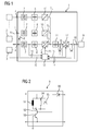
- FIG. 2 shows a preferred circuit of the MPP controller 9.
- the MPP controller 9 has an inductance 91 which is connected on the one hand with a connection to the high potential side terminal of the smoothed by the capacitance 8 input voltage of the converter module 1.
- the inductance 91 with its second connection can be selectively switched via a switch 92 to the collector terminal of a transistor 93.
- the transistor 93 is connected at its base and emitter terminals to the low potential side terminal of the smoothed voltage of the capacitor 8, respectively.
- a parallel connection of a resistor 94 and a diode 95 is also connected to the high potential side terminal of the smoothed voltage of the smoothing capacitor 8.
- the cathode-side N terminal of the diode 95 is connected to the high potential side terminal of the parallel circuit of diode 95 and resistor 94.
- the anode-side P terminal of the diode 95 is connected to the low-potential side terminal of the parallel circuit of the diode 95 and the resistor 94.
- Switch 92 may selectively connect the collector terminal of transistor 93 to either the low potential side terminal of inductor 91 or the low potential side terminal of parallel resistor 94 and diode 95 terminal.
- a diode 96 is connected to the collector terminal of the transistor 95 with its P terminal. N- or cathode side, the diode 96 forms the high-potential-side output terminal of the MPP controller 9.
- the emitter terminal of the transistor 95 forms the low-potential-side output terminal of the MPP controller.
- the MPP controller 9 In a first position in which the switch 92 connects the transistor 93 to the inductor 91, the MPP controller 9 operates as a boost converter and can regulate the injected power according to an MPP controller or tracker. That is the MPP controller 9 follows the maximum power point (MPP) of the PV system connected on the input side (PV field or PV array) and regulates its operating point accordingly to the MPP of the current state of the PV system.
- MPP maximum power point
- the MPP controller 9 operates as a chopper in a chopper circuit, in which, for example as a result of a power take-off overvoltages 94th derived and thus the subsequent circuit parts are protected against overload.
Landscapes
- Engineering & Computer Science (AREA)
- Power Engineering (AREA)
- Inverter Devices (AREA)
Abstract
Die Erfindung betrifft ein Umrichtermodul (1) mit mindestens einem Moduleingang (4) zum Anschluss einer Gleichstromquelle (2) oder einer Wechselstromquelle (3) und mit einem Modulausgang (18) zum Anschluss einer Stromsenke, mit mindestens einem ersten Maximum-Power-Point-Steller (9), der zur Steuerung sowohl einer eingangsseitig eingespeisten Gleichspannung als auch einer eingangsseitig eingespeisten gleichgerichtete Wechselspannung zwischen einem Hochsetzstellermodus und einem Choppermodus umschaltbar ist, mit einer Wechselrichterstufe (12), welche die eingespeiste Gleichspannung in eine Wechselspannung umsetzt, sowie mit einer Steuereinheit (13) zur Steuerung der Wechselrichterstufe (12) und des Maximum-Power-Point-Stellers (9).The invention relates to an inverter module (1) having at least one module input (4) for connecting a direct current source (2) or an alternating current source (3) and having a module output (18) for connecting a current sink, with at least one first maximum power point. Actuator (9), which is switchable between a boost converter mode and a chopper mode for controlling both a DC voltage supplied on the input side and a rectified AC voltage input, with an inverter stage (12) which converts the DC voltage fed into an AC voltage, and a control unit (9). 13) for controlling the inverter stage (12) and the maximum power point adjuster (9).
Description
Die Erfindung betrifft ein Umrichtermodul, insbesondere für eine Photovoltaikanlage und/oder eine Wind- und Wasserkraftanlage, mit mindestens einem Moduleingang zum Anschluss einer Gleichstromquelle oder einer Wechselstromquelle und mit einem Modulausgang zum Anschluss einer Stromsenke, insbesondere an ein Energieverteilungsnetz.The invention relates to an inverter module, in particular for a photovoltaic system and / or a wind and hydroelectric power plant, with at least one module input for connecting a DC power source or an AC power source and with a module output for connecting a current sink, in particular to an energy distribution network.
Um regenerative Energie nutzen zu können, werden zusätzlich zu stromerzeugenden Elementen (Generatoren) auch Geräte benötigt, die die Energie geeignet in das öffentliche Netz einspeisen. Diese Geräte werden als Umrichter, Wechselrichter oder Inverter bezeichnet. In Photovoltaikanlagen (PV-Anlagen) und in Wind- bzw. Wasserkraftanlagen werden üblicherweise jeweils unterschiedliche Umrichter eingesetzt. Insbesondere zur kostentechnisch möglichst effektiven Handhabung der genannten Unterschiede in den Energiearten werden bisher unterschiedliche Umrichter entwickelt, die lediglich auf den jeweiligen Generatortyp abgestimmt sind.In order to be able to use regenerative energy, devices are needed in addition to electricity-generating elements (generators) that feed the energy into the public grid. These devices are called inverters, inverters or inverters. In photovoltaic systems (PV systems) and wind or hydroelectric plants usually different converters are used. In particular, for the most cost-effective handling of the aforementioned differences in the types of energy so far different converters are developed, which are tuned only to the respective generator type.
PV-Umrichter können eingangsseitig mit einem DC/DC-Wandler (Step-Up-Wandler) ausgerüstet sein, der die Eingangsspannung aus den PV-Feldern in eine höhere Spannung umsetzt. Um ein PV-Feld dynamisch am sogenannten MPP (Maximum Power Point) zu betreiben, wird eine als MPP-Steller bezeichnete Funktionseinheit innerhalb des PV-Umrichters eingesetzt.PV inverters can be equipped on the input side with a DC / DC converter (step-up converter), which converts the input voltage from the PV fields into a higher voltage. To operate a PV field dynamically at the so-called MPP (Maximum Power Point), a functional unit called MPP controller is used within the PV inverter.
MPP-Steller messen die Eingangsspannung und den Eingangsstrom, berechnen daraus die Eingangsleistung und steuern über eine Steuereinrichtung (Control Unit) in den DC/DC-Wandlern vorgesehene Leistungsschalter. Der Ablauf einer MPP-Regelung wird üblicherweise durch die sogenannte Firmware in der Steuereinheit bestimmt. Diese Steuereinheit (Control Unit) wird üblicherweise als Microcontroller oder digitaler Signalprozessor ausgeführt. Während Regelungsalgorithmen die Leistungselektronik steuern, regelt eine Ablaufsteuerung die Funktion des gesamten Gerätes. Zweckmäßigerweise werden mehrere MPP-Steller eingesetzt, wenn mehrere PV-Felder unterschiedlich ausgerichtet oder unterschiedlich verschaltet sind.MPP controllers measure the input voltage and the input current, calculate the input power and control circuit breakers in the DC / DC converters via a control unit. The course of an MPP control is usually determined by the so-called firmware in the control unit. This control unit (control unit) is usually designed as a microcontroller or digital signal processor. During control algorithms the power electronics control, a sequence control regulates the function of the entire device. It is expedient to use a plurality of MPP controllers if a plurality of PV fields are differently oriented or differently interconnected.
Bei Wind- und Wasserkraftanlagen sind unterschiedliche Energieumwandlungen möglich. Je nach Leistungsklasse kommen verschiedene technische Ausführungen von Umrichtern zum Einsatz. Große Windräder oberhalb einer Leistungsklasse von ca. 100KW weisen einen speziellen Generator auf, welcher Energie mittels zusätzlicher Leistungselektronik direkt in das öffentliche Netz einspeist. Hierbei werden doppelt gespeiste Asynchronmaschinen als Energiequelle für das öffentliche Netz verwendet.In wind and hydro power plants different energy conversions are possible. Depending on the performance class, various technical versions of inverters are used. Large wind turbines above a power class of about 100KW have a special generator, which feeds energy directly into the public grid by means of additional power electronics. Here, doubly fed asynchronous machines are used as power source for the public network.
Bei kleineren Leistungen (ca. 5KW bis 50KW) wandelt ein aktiv geregelter oder ein ungeregelter Brückengleichrichter (in B4- oder B6-Schaltung) die Wechselspannung in eine pulsierende Gleichspannung um. Ein DC/DC-Wandler (Step-Up-Wandler) setzt diese Gleichspannung in eine höhere Gleichspannung um. Ein nachgeschaltetes Wechselrichtermodul, z. B. in B6C-oder NPC-Schaltung oder ein Matrix-Inverter, erzeugt daraus eine stromgeregelt stabilisierte Wechselspannung für die Einspeisung in das öffentliche Netz (Verbundnetz).For smaller powers (about 5KW to 50KW), an actively regulated or an unregulated bridge rectifier (in B4 or B6 circuit) converts the AC voltage into a pulsating DC voltage. A DC / DC converter (step-up converter) converts this DC voltage into a higher DC voltage. A downstream inverter module, z. B. in B6C or NPC circuit or a matrix inverter, it generates a current-stabilized AC voltage for feeding into the public network (interconnected network).
Bei Umrichtern für gleichgerichtete Wechselspannungen aus drehenden Generatoren erfolgt die Regelung der Ausgangsleistung über die Spannungshöhe am Eingang des DC/DC-Wandlers. Typischerweise kann durch eine Spannungs-Leistungs-Zuordnung (U- zu P- Zuordnung) eine Anpassung des Generators an die Ausgangsleistung des DC/DC-Wandlers und/oder nachgeschalteter Wechselrichtereinheit (Inverter) erfolgen.In converters for rectified AC voltages from rotating generators, the output power is controlled by the voltage level at the input of the DC / DC converter. Typically, by a voltage-power assignment (U to P assignment), an adaptation of the generator to the output power of the DC / DC converter and / or downstream inverter unit (inverter).
Kritisch ist bei sich drehenden Generatoren eine spontan fehlende Belastung. Dies kann beispielsweise durch eine Abschaltung des Inverters erfolgen, wenn dieser einen Netzfehler (Frequenzfehler, Impedanzfehler, Phasenausfall oder dergleichen), eine Störung im Umrichter und/oder eine Störungen durch den Generator feststellt.Critically, rotating generators have a spontaneously missing load. This can be done for example by a shutdown of the inverter, if this a network error (frequency error, impedance error, phase failure or the like), detects a fault in the inverter and / or a fault by the generator.
Während die Induktivitäten in den Generatoren gemäß der Lenz'schen Regel den Strom weiter in die Last (Umrichter) treiben, würde bei fehlender Last die Eingangsspannung am Umrichter sprunghaft ansteigen. Um solche sprunghaften Spannungsanstiege zu beherrschen, sind Schutzbeschaltungen oder Eingangsschaltungen vorgesehen, die auch als Chopperschaltungen bezeichnet werden. Diese begrenzen bei Umrichtern für Wind- und Wasserkraftanlagen die Eingangsspannung an den DC/DC-Wandlern (Step-Up-Wandlern) auf eine für die Leistungshalbleiter zulässige Maximalspannung. Derartige Chopperschaltungen schalten Lastwiderstände in den Eingangskreis und übernehmen bis zur Absenkung der Erregung des Generators oder bis zur anderweitigen Generatorabschaltung die überschüssige Energie.While the inductors in the generators continue to drive the current into the load (inverter) according to Lenz's rule, the input voltage at the inverter would increase abruptly in the absence of load. In order to control such sudden voltage increases, protective circuits or input circuits are provided, which are also referred to as chopper circuits. These limit the input voltage at the DC / DC converters (step-up converters) to a maximum voltage permissible for the power semiconductors in converters for wind and hydroelectric power plants. Such chopper circuits switch load resistors in the input circuit and take over until the reduction of the excitation of the generator or to the other generator shutdown the excess energy.
Bisher werden Geräte speziell für den jeweiligen Anwendungsfall (Windwechselrichter-Wasserkraft-Wechselrichter oder PV-Wechselrichter) entwickelt und betrieben, was mit hohen Kosten verbunden ist.Until now, devices have been developed and operated especially for the respective application (wind inverter-hydropower inverter or PV inverter), which is associated with high costs.
Der Erfindung liegt die Aufgabe zugrunde, ein Umrichtermodul bereitzustellen, welches eine alternative und eine gemeinsame Nutzung von Photovoltaikanlagen und Wind- oder Wasserkraftanlagen als Stromquelle ermöglicht. Dabei sollen insbesondere externe Schutzbeschaltung oder ein externer Eingangs-Chopper vermieden werden.The invention has for its object to provide a converter module, which allows an alternative and a common use of photovoltaic systems and wind or hydroelectric power plants as a source of electricity. In particular, external protective circuit or an external input chopper should be avoided.
Diese Aufgabe wird erfindungsgemäß gelöst durch die Merkmale des Anspruches 1. Vorteilhafte Ausgestaltungen sind in den Unteransprüchen angegeben.This object is achieved by the features of claim 1. Advantageous embodiments are specified in the dependent claims.
Hierzu ist ein Umrichtermodul mit Moduleingängen zum Anschluss von Gleich- und Wechselstromquellen und mit einem Modulausgang zum Anschluss einer Stromsenken sowie mit mindestens einem ersten Maximum-Power-Point-Steller (MPP-Steller), der zur Steuerung sowohl einer eingangsseitig eingespeisten Gleichspannung als auch einer eingangsseitig eingespeisten gleichgerichtete Wechselspannung zwischen einem Hochsetzstellermodus und einem Choppermodus umschaltbar ist. Die Umschaltung zwischen dem Hochsetzstellermodus und dem Choppermodus erfolgt mittels einer Steuereinheit, die zudem eine Wechselrichterstufe steuert, welche die eingespeiste Gleichspannung in eine Wechselspannung umsetzt.This includes a converter module with module inputs for connecting DC and AC sources and with a module output for connecting a current sink and at least one first maximum power point controller (MPP controller), which can be switched between a boost converter mode and a chopper mode for controlling both a DC voltage input on the input side and a rectified AC voltage input on the input side. The switching between the boost converter mode and the chopper mode is carried out by means of a control unit, which also controls an inverter stage, which converts the DC voltage fed into an AC voltage.
Gemäß einer zweckmäßigen Weiterbildung weist der MPP-Steller sowohl eine Hochsetzstellerschaltung mit einem Halbleiterschalter und mit einer Induktivität als auch eine Chopperschaltung mit einem ohmschen Widerstand sowie einen ansteuerbaren Schalter zur Umschaltung zwischen dem Choppermodus und dem Hochsetzstellermodus auf. Damit können die verschiedenen Eingangsspannungsarten und deren Kennlinien in dem MPP-Steller verarbeitet und eine konstante geregelte Spannung für den nachfolgenden Wechselrichtermodul bereitgestellt werden. Zudem wird eine externe Chopperbeschaltung vermieden und somit Bauraum eingespart.According to an expedient development, the MPP controller has both a step-up converter circuit with a semiconductor switch and with an inductor and a chopper circuit with an ohmic resistance and a controllable switch for switching between the chopper mode and the boost converter mode. This allows the various types of input voltages and their characteristics to be processed in the MPP controller and to provide a constant regulated voltage for the subsequent inverter module. In addition, an external Chopperbeschaltung is avoided, thus saving space.
Vorzugsweise ist dem Halbleiterschalter im Hochsetzstellermodus eine Induktivität und im Choppermodus der ohmsche Widerstand vorgeschaltet. Dadurch kann der MPP-Steller einerseits im Hochsetzstellermodus und andererseits im Choppermodus arbeiten, um überschüssige, Energie über den ohmschen Widerstand abzuführen. Der Choppermodus dient insbesondere zum Schutz des dem MPP-Steller nachgeordneten Wechselrichters (Wechselrichterstufe), insbesondere wenn bei eingangsseitig angeschlossener, generatorisch arbeitender Wind- oder Wasserkraftanlage im Falle eines Netzabwurfs die Spannung am MPP-Steller sprungartig und/oder auf hohe Spannungswerte ansteigt.In the boost converter mode, the semiconductor switch is preferably preceded by an inductance and in chopper mode by the ohmic resistance. As a result, the MPP controller can work in boost converter mode on the one hand and in chopper mode on the other hand to dissipate excess energy via the ohmic resistor. The chopper mode is used in particular for the protection of the MPP actuator downstream inverter (inverter stage), especially when connected on the input side, generator operating wind or hydropower plant in the case of a network drop, the voltage at the MPP controller jumps and / or rises to high voltage values.
Vorzugsweise ist zwischen dem Eingangsfilter und dem MPP-Steller eine Kapazität angeordnet. Dadurch ist eine Glättungsmöglichkeit der Eingangsspannung geschaffen. Änderungen in der Eingangsspannung oder in der Belastung können kurzfristig durch die Kapazität ausgeglichen werden.Preferably, a capacitance is arranged between the input filter and the MPP controller. This creates a possibility of smoothing the input voltage. amendments in the input voltage or in the load can be compensated in the short term by the capacity.
Vorzugsweise ist auch zwischen dem MPP-Steller und dem Wechselrichtermodul eine Kapazität angeordnet. Damit ist eine Glättungsmöglichkeit der geregelten Spannung am Ausgang des MPP-Stellers geschaffen. Änderungen in der geregelten Spannung oder in der Belastung durch den Wechselspannungsrichter können kurzfristig durch die Kapazität ausgeglichen werden.Preferably, a capacitance is also arranged between the MPP controller and the inverter module. This creates a smoothing option for the regulated voltage at the output of the MPP controller. Changes in the regulated voltage or in the load by the AC voltage converter can be compensated in the short term by the capacity.
Gemäß einer vorteilhaften Weiterbildung weist das Umrichtermodul wenigsten einen weiteren Eingangsfilter auf. Darüber hinaus ist zwischen wenigstens einem weiteren MPP-Steller und dem weiteren Eingangsfilter eine weitere Kapazität vorgesehen, welche eine geglättete Eingangsspannung bereitstellt.According to an advantageous development, the converter module has at least one further input filter. In addition, a further capacitor is provided between at least one further MPP controller and the further input filter, which provides a smoothed input voltage.
Vorzugsweise erfolgt die Energieversorgung der Steuereinheit über eine der Wechselrichterstufe gleichstromseitig vorgeordnete erste Diode und/oder über eine der Wechselrichterstufe wechselstromseitig nachgeordnete zweite Diode. Somit ist es möglich, die Steuereinheit bei ausreichender Sonneneinstrahlung, insbesondere tagsüber, über eine eingangsseitig angeschlossene PV-Anlage (PV-Array) und bei nicht ausreichender Sonnenstrahlung, beispielsweise nachts oder bei starker Bewölkung, über das ausgangsseitig angeschlossene Energieverteilungsnetz (öffentliches Stromverteilnetz) zu versorgen.The power supply of the control unit preferably takes place via a first diode arranged on the DC side of the inverter stage and / or via a second diode downstream of the inverter stage on the AC side. Thus, it is possible to provide the control unit with sufficient sunlight, especially during the day, via an input side connected PV system (PV array) and insufficient solar radiation, for example, at night or in heavy cloudy, on the output side connected power distribution network (public power distribution network) ,
Gemäß einer vorteilhaften Weiterbildung ist mindestens ein dritter Maximum-Power-Point Steller dem Wechselrichter vorgeschaltet. Damit kann gleichzeitig zu einem Wind- oder Wasserkraftgenerator auch eine PV-Anlage an das Umrichtermodul angeschlossen werden.According to an advantageous development, at least a third maximum power point actuator is connected upstream of the inverter. This can be connected to the inverter module at the same time to a wind or hydropower generator and a PV system.
In einer geeigneten Ausführungsform ist das Umrichtermodul eingangsseitig zum Anschluss mindestens einer Batterie, mindestens einer PV-Anlage, mindestens einer Wind- oder Wasserkraftgeneratoranlage und ausgangsseitig zum Anschluss insbesondere an ein öffentliches Stromverteilnetz und/oder an eine Batterie vorgesehen und eingerichtet.In a suitable embodiment, the converter module is on the input side for connecting at least one battery, at least one PV system, at least one wind or hydropower generator system and on the output side to the connection in particular provided and set up to a public power distribution network and / or to a battery.
Nachfolgend werden Ausführungsbeispiele der Erfindung anhand einer Zeichnung näher erläutert, darin zeigen:
- FIG 1
- ein Blockdiagramm eines Umrichters mit einem zwischen zwei Modi umschaltbaren MPP-Steller, und
- FIG 2
- eine elektronische Schaltung des umschaltbaren MPP-Stellers.
- FIG. 1
- a block diagram of an inverter with a switchable between two modes MPP-controller, and
- FIG. 2
- an electronic circuit of the switchable MPP controller.
In einer Photovoltaikanlagen (PV-Anlage) liefern PV-Felder mit in Reihenschaltung und Parallelschaltung angeordneten Solarmodulen quasi als Generator direkt eine Gleichspannung, während Wind- und Wasserkraftanlagen aus drehenden Generatoren eine Wechselspannung erzeugen. Zusätzlich zu der unterschiedlichen Spannungsart weisen PV-Felder eine andere Leistungskennlinie als drehende Generatoren auf.In a photovoltaic system (PV system) supply PV array with arranged in series and parallel circuit solar modules quasi as a generator directly a DC voltage, while wind and hydro power plants from rotating generators generate an AC voltage. In addition to the different voltage type, PV fields have a different performance characteristic than rotating generators.
PV-Felder zeigen einen von der Substrat-Temperatur und der Einstrahlungsintensität des Sonnenlichtes abhängigen und veränderlichen Punkt, an dem die Leistungsabgabe am größten ist. Dieser Punkt wird als MPP (Maximum Power Point) bezeichnet. Je größer der durch die Solarfelder fließende Strom bei gleichen Bedingungen ist, umso kleiner ist die abgebende Gleichspannung.PV fields show a point that is dependent on the substrate temperature and the intensity of insolation of the sunlight and that is variable, at which the power output is greatest. This point is called MPP (Maximum Power Point). The larger the current flowing through the solar fields under the same conditions, the smaller the output DC voltage.
Im Gegensatz dazu steigen bei einem drehendem Wind- oder Wasserkraftgenerator die Wechselspannungshöhe und die Leistungsabgabe mit zunehmender Generator-Drehzahl an.In contrast, with a rotating wind or hydro generator, the AC level and power output increase with increasing generator speed.
Generatoren für Windkraft und Wasserkraft weisen einen Rotor und einen mit Spulen mit definierten Induktivitäten bewickelten Stator auf. Dreht sich ein magnetisch wirksamer Rotor gegenüber dem Stator des Generators, so wird eine Spannung in der äußeren Statorwicklung induziert. Wird die Statorwicklung elektrisch belastet, so fließt z. B. ein sinusförmiger Strom durch diese Wicklung. Unterschiedliche Drehzahlen haben einen großen Einfluss auf die Höhe der Ausgangsspannung. Ebenso ist der Unterschied der Spannungshöhe zwischen einer belasteten und einer unbelasteten Wicklung erheblich.Wind and hydro generators have a rotor and a stator wound with coils of defined inductance. When a magnetically active rotor rotates relative to the stator of the generator, a voltage is induced in the outer stator winding. If the stator winding is electrically loaded, then flows z. B. a sinusoidal current through this winding. Different speeds have one great influence on the level of the output voltage. Similarly, the difference in voltage level between a loaded and an unloaded winding is significant.
In dem in
Das Umrichtermodul 1 weist mehrere Eingänge 4 zum Anschluss von Gleichspannungsquellen 2 oder Wechselspannungsquellen 3 auf. Die Moduleingänge 4 sind auch über eine Brücke 5 verbindbar, die im Falle des Anschlusses einer Wechselspannungsquelle 3 gesetzt werden sollte. Ein solcher Moduleingang 4 des Umrichtermoduls 1 dient somit zur Einspeisung einer Gleichspannung oder einer gleichgerichteten Wechselspannung, wobei im Falle einer eingespeisten gleichgerichteten Wechselspannung zwei Moduleingänge 4 belegt sind. Es steht auch mindestens ein weiterer Moduleingang 4 bereit, an den eine weitere Gleichspannungsquelle 2 angeschlossen werden kann. So können gleichzeitig auch mehrere gleichartige oder unterschiedliche Energiequellen 2, 3 an die Eingänge oder Moduleingänge 4 des Umrichtermoduls 1 angeschlossen sein.The converter module 1 has a plurality of
Alternativ zur Verbindung der Moduleingänge 4 mittels einer Brücke 5 kann auch umrichtermodulintern ein Schalter 6 vorgesehen sein, welcher die Überbrückungsfunktion intern übernimmt. Diese Überbrückungsfunktion ist bevorzugt zu realisieren, wenn ein gleichgerichteter Wechselstrom aus einer Wechselspannungsquelle 3 an einem der Eingangsanschlüsse 4 eingespeist wird.As an alternative to the connection of the
Das Umrichtermodul 1 weist mehrere Stränge S1, S2 bis Sn mit jeweils einem Eingangsfilter 7, einer Kapazität 8 und einem Maximum-Power-Point-(MPP-)Steller 9, 10 auf. Dabei ist ein erster Strang S1 mit einem MPP-Steller 9 ausgestattet, der zusätzlich zu einem Hochsetzstellermodus auch eine sogenannte Chopperschaltung realisiert. Die anderen MPP-Steller 10 arbeiten bevorzugt lediglich als Hochsetzsteller unter Berücksichtigung der Kennlinien einer PV-Anlage 2 bzw. der Generatorkennlinien einer Wind- oder Wasserkraftanlage als Wechselspannungsquelle 3.The converter module 1 has a plurality of strings S 1 , S 2 to S n , each having an
Jeder der Stränge S1, S2, Sn erhält eine Eingangsspannung, welche an einem oder mehreren der Moduleingänge 4 bereit gestellt ist. Die Eingangsspannung wird durch den Eingangsfilter 7 von unerwünschten Oberschwingungen und hochfrequenten Signalanteilen befreit. Die durch den Eingangsfilter 7 geglättete Spannung lädt die Kapazität 8 in Form eines oder mehrerer Kondensatoren auf. Die geglättete Ausgangsspannung der Kapazität 8 wird in den MPP-Steller 9, 10 gespeist, der die an diesem anliegende Spannung bzw. den Strom auf den Maximum-Power-Point im Falle einer PV-Anlage oder mit Hilfe einer Leistungskennlinie des am Eingang angeschlossenen Generators einer Wechselspannungsquelle regelt.Each of the strings S 1 , S 2 , S n receives an input voltage which is provided at one or more of the
Dem MPP-Steller 9, 10 ist ein Kapazität 11 in Form eines oder mehrerer Kondensatoren nachgeschaltet, welche zusammen mit dem MPP-Steller 9, 10 wirkt und die geregelte Spannung als weiteres Energiereservoir glättet sowie dieses den nachfolgenden Kreisen bereitstellt. Ein dem MPP-Steller 9, 10 nachgeordneter Wechselrichter 12 richtet die in diesen eingespeiste Gleichspannung in eine Wechselspannung zur Einspeisung in ein Netz um.The
Treten unerwünschte Spannungsspitzen auf, kann der MPP-Steller 9 in Strang S1 die kurzfristige Überlastung durch eine interne Schaltung (Chopperbeschaltung) abfangen und somit nachfolgende Bauteile vor Überspannung und Überbeanspruchung schützen. Umrichtermodulintern können mehrere Stränge S1, S2, Sn mit Eingangsfilter 7, Kapazität 8 und MPP-Steller 9, 10, korrespondierend zu der Anzahl der Moduleingänge 4 vorgesehen sein. Diese sind jeweils parallel der Kapazität 11 vorgeschaltet.If unwanted voltage peaks occur, the
Eine Steuereinheit oder -einrichtung 13 in Form vorzugsweise eines Microcontrollers wertet Messungen, insbesondere vor und hinter dem Wechselrichter 12 sowie zwischen dem Eingangsfilter 7 und der Kapazität 8 vorgenommene Strom- und/oder Spannungsmessungen, aus. Entsprechende Messwerte werden über Messleitungen 14 an die Steuereinheit 13 geführt. Anhand der Messungen bzw. Messwerte steuert die Steuereinheit 13 über Steuerleitungen 15 in den relevanten Blöcken 9, 10 und 12 vorgesehene Schalter und/oder Transistoren. Zusätzlich dazu steuert die Steuereinheit 13 auch den Umschalter 6, welcher in Schließstellung zwei Stränge S1 und S2 mit Eingangsfilter 7, Kapazität 8, MPP-Steller 9 bzw. Eingangsfilter 7, Kapazität 8 und MPP-Steller 10 eingangsseitig parallel schaltet und beispielsweise eine PV-Anlage und/oder eine Wind-/Wasserkraftanlage an das Umrichtermodul 1 anschließt.A control unit or
Zur Spannungsversorgung der Steuereinheit 13 sind Dioden 16 und 17 vorgesehen, die gleich- bzw. wechselstromseitig an den Wechselrichter 12 angeschlossen sind. Insbesondere tagsüber kann somit die Steuereinheit 13 mittels der gelieferten Energie z. B. einer angeschlossenen PV-Anlage über die Diode 16 gespeist werden. Liefert die PV-Anlage beispielsweise Nachts oder bei starker Bewölkung keine ausreichende Energie, so kann die Steuereinheit 13 von einem ausgangsseitig mit einem Modulausgang oder -anschluss 18 des Umrichtermoduls 1 verbundenen Energieverteilungs- oder Versorgungsnetz 19 über die Diode 17 je nach Betriebsart versorgt werden.To supply power to the
Letztlich wird die aufbereitete und wechselgerichtete Gleichspannung am Modulausgang 18 des Umrichtermoduls 1 zur Verfügung gestellt und kann in das Energieverteilungsnetz 19 eingespeist werden.Finally, the processed and reversed DC voltage is provided at the
Eine Parallelschaltung eines Widerstandes 94 und einer Diode 95 ist ebenfalls an den hochpotentialseitigen Anschluss der geglätteten Spannung der Glättungskapazität 8 angeschlossen. Der kathodenseitige N-Anschluss der Diode 95 ist dabei an dem hochpotentialseitigen Anschluss der Parallelschaltung aus Diode 95 und Widerstand 94 angeschlossen. Der anodenseitige P-Anschluss der Diode 95 ist an dem niederpotentialseitigen Anschluss der Parallelschaltung aus Diode 95 und Widerstand 94 angeschlossen.A parallel connection of a
Der Schalter 92 kann den Kollektor-Anschluss des Transistors 93 selektiv entweder an den niederpotentialseitigen Anschluss der Induktivität 91 oder an den niederpotentialseitigen Anschluss der Parallelschaltung aus Widerstand 94 und Diode 95 anschließen. Eine Diode 96 ist an den Kollektoranschluss des Transistors 95 mit deren P-Anschluss geschaltet. N- bzw. kathodenseitig bildet die Diode 96 den hochpotentialseitigen Ausgangsanschluss des MPP-Stellers 9. Der Emitteranschluss des Transistors 95 bildet den niederpotentialseitigen Ausgangsanschluss des MPP-Stellers 9.
In einer ersten Stellung, in der der Schalter 92 den Transistor 93 mit der Induktivität 91 verbindet, arbeitet der MPP-Steller 9 als Hochsetzsteller und kann die eingespeiste Leistung gemäß eines MPP-Stellers oder -Trackers regeln. D.h. der MPP-Steller 9 folgt dem Maximum Power Point (MPP) der eingangsseitig angeschlossenen PV-Anlage (PV-Feld oder PV-Array) und regelt seinen Arbeitspunkt entsprechend auf den MPP des gerade aktuellen Zustandes der PV-Anlage.In a first position in which the
In einer zweiten Stellung, in welcher der Schalter 92 den Transistor 93 mit der Parallelschaltung aus Diode 95 und Widerstand 94 verbindet, arbeitet der MPP-Steller 9 als in einem Choppermodus als Chopperschaltung, in dem beispielsweise in Folge eines Netzabwurfes entstehende Überspannungen über den Widerstand 94 abgeleitet und somit die nachfolgenden Schaltungsteile gegen eine Überlastung geschützt werden.In a second position, in which the
Die Erfindung ist nicht auf die vorstehend beschriebene Ausführungsbeispiele beschränkt. Vielmehr können auch andere Varianten der Erfindung von dem Fachmann hieraus abgeleitet werden, ohne den Gegenstand der Erfindung zu verlassen. Insbesondere sind ferner alle im Zusammenhang mit den Ausführungsbeispielen beschriebenen Einzelmerkmale auch auf andere Weise miteinander kombinierbar, ohne den Gegenstand der Erfindung zu verlassen.The invention is not limited to the embodiments described above. Rather, other variants of the invention can be derived therefrom by the person skilled in the art without departing from the subject matter of the invention. In particular, all the individual features described in connection with the exemplary embodiments can also be combined with one another in other ways, without departing from the subject matter of the invention.
Claims (10)
dadurch gekennzeichnet, dass der Maximum-Power-Point-Steller (9) sowohl eine Hochsetzstellerschaltung mit einem Halbleiterschalter (93) und mit einer Induktivität (91) als auch eine Chopperschaltung mit einem ohmschen Widerstand (94) sowie einen ansteuerbaren Schalter (92) zur Umschaltung zwischen dem Choppermodus und dem Hochsetzstellermodus umfasst.Inverter module (1) according to claim 1,
characterized in that the maximum power point actuator (9) both a boost converter circuit with a semiconductor switch (93) and with an inductance (91) and a chopper circuit with an ohmic resistance (94) and a controllable switch (92) for Switching between the chopper mode and the boost converter mode includes.
dadurch gekennzeichnet, dass dem Halbleiterschalter (93) im Hochsetzstellermodus die Induktivität (91) und im Choppermodus der ohmsche Widerstand (94) vorgeschaltet ist.Inverter module (1) according to claim 2,
characterized in that the semiconductor switch (93) in the boost converter mode, the inductance (91) and in the chopper mode of the ohmic resistance (94) is connected upstream.
gekennzeichnet durch mindestens einen zweiten Maximum-Power-Point-Steller (10), der eingangsseitig dem ersten Maximum-Power-Point-Steller (9) mittels einer Brücke (5) oder über einem Schalter (6) parallel geschaltet istInverter module (1) according to one of claims 1 to 3,
characterized by at least one second maximum power point controller (10), the input side of the first Maximum power point actuator (9) by means of a bridge (5) or via a switch (6) is connected in parallel
dadurch gekennzeichnet, dass dem oder jedem Maximum-Power-Point-Steller (9, 10) über eine Kapazität (8) ein Eingangsfilter (7) zur Filterung des Eingangssignals vorgeschaltet angeordnet ist.Inverter module (1) according to one of claims 1 to 4,
characterized in that the or each maximum power point controller (9, 10) via a capacitance (8) an input filter (7) is arranged upstream of the filtering of the input signal.
dadurch gekennzeichnet, dass der Wechselrichterstufe (12) eine Kapazität (11) vorgeschaltet ist.Inverter module (1) according to one of claims 1 to 5,
characterized in that the inverter stage (12) is preceded by a capacitor (11).
dadurch gekennzeichnet, dass die Energieversorgung der Steuereinheit (13) über eine der Wechselrichterstufe (12) gleichstromseitig vorgeordnete erste Diode (16) und/oder über eine der Wechselrichterstufe (12) wechselstromseitig nachgeordnete zweite Diode (17) erfolgt.Inverter module (1) according to one of claims 1 to 6,
characterized in that the power supply of the control unit (13) via one of the inverter stage (12) on the DC side upstream first diode (16) and / or via one of the inverter stage (12) on the AC side downstream second diode (17).
dadurch gekennzeichnet, dass der dem Wechselrichter (12) vorgeschalteten Kapazität (11) mindestens ein dritter Maximum-Power-Point-Steller (10) vorgeschaltet ist.Inverter module (1) according to one of Claims 1 to 7,
characterized in that the inverter (12) upstream of the capacitance (11) at least a third maximum power-point adjuster (10) is connected upstream.
Priority Applications (1)
| Application Number | Priority Date | Filing Date | Title |
|---|---|---|---|
| EP13163705.0A EP2793384A1 (en) | 2013-04-15 | 2013-04-15 | Converter module |
Applications Claiming Priority (1)
| Application Number | Priority Date | Filing Date | Title |
|---|---|---|---|
| EP13163705.0A EP2793384A1 (en) | 2013-04-15 | 2013-04-15 | Converter module |
Publications (1)
| Publication Number | Publication Date |
|---|---|
| EP2793384A1 true EP2793384A1 (en) | 2014-10-22 |
Family
ID=48092812
Family Applications (1)
| Application Number | Title | Priority Date | Filing Date |
|---|---|---|---|
| EP13163705.0A Withdrawn EP2793384A1 (en) | 2013-04-15 | 2013-04-15 | Converter module |
Country Status (1)
| Country | Link |
|---|---|
| EP (1) | EP2793384A1 (en) |
Citations (4)
| Publication number | Priority date | Publication date | Assignee | Title |
|---|---|---|---|---|
| US20080164766A1 (en) * | 2006-12-06 | 2008-07-10 | Meir Adest | Current bypass for distributed power harvesting systems using dc power sources |
| WO2009039887A1 (en) * | 2007-09-27 | 2009-04-02 | Conergy Ag | Dc control unit for controlling an input voltage in a photovoltaic system |
| WO2011066121A1 (en) * | 2009-11-25 | 2011-06-03 | American Superconductor Corporation | Reducing photovoltaic array voltage during inverter re-enablement |
| US20120087158A1 (en) * | 2011-10-17 | 2012-04-12 | Solarbridge Technologies, Inc. | Method and Apparatus for Controlling an Inverter Using Pulse Mode Control |
-
2013
- 2013-04-15 EP EP13163705.0A patent/EP2793384A1/en not_active Withdrawn
Patent Citations (4)
| Publication number | Priority date | Publication date | Assignee | Title |
|---|---|---|---|---|
| US20080164766A1 (en) * | 2006-12-06 | 2008-07-10 | Meir Adest | Current bypass for distributed power harvesting systems using dc power sources |
| WO2009039887A1 (en) * | 2007-09-27 | 2009-04-02 | Conergy Ag | Dc control unit for controlling an input voltage in a photovoltaic system |
| WO2011066121A1 (en) * | 2009-11-25 | 2011-06-03 | American Superconductor Corporation | Reducing photovoltaic array voltage during inverter re-enablement |
| US20120087158A1 (en) * | 2011-10-17 | 2012-04-12 | Solarbridge Technologies, Inc. | Method and Apparatus for Controlling an Inverter Using Pulse Mode Control |
Non-Patent Citations (1)
| Title |
|---|
| "SPV1020", 25 May 2012 (2012-05-25), STMircroelectronics website, pages 1 - 20, XP055076795, Retrieved from the Internet <URL:http://www.st.com/st-web-ui/static/active/en/resource/technical/document/datasheet/CD00275733.pdf> [retrieved on 20130828] * |
Similar Documents
| Publication | Publication Date | Title |
|---|---|---|
| EP1971019B1 (en) | Switching device for transformerless conversion of an electric direct current into an AC voltage with two DC/DC converters and a DC/AC converter | |
| EP3022835B1 (en) | Inverter comprising at least two direct current inputs, a photovoltaic installation comprising such an inverter, and a method for actuating an inverter | |
| DE102015109724A1 (en) | A system and method for protecting a power converter during an unwanted voltage event | |
| DE102004001478B4 (en) | Converter circuit arrangement for converting an alternating voltage into a high-voltage direct voltage | |
| EP2445077B1 (en) | Photovoltaic assembly with reactive power generation dependent on mains voltage | |
| DE102013212682B4 (en) | Energy storage device with DC power supply circuit and method for providing a DC voltage from an energy storage device | |
| EP2994969B1 (en) | Assembly for compensating reactive power and active power in a high-voltage network | |
| EP2408081A1 (en) | Modular multi-level converter | |
| WO2014086696A2 (en) | Photovoltaic system and method for operating a photovoltaic system | |
| WO2013124079A1 (en) | System and method for actuating an energy storage device | |
| WO2014154495A1 (en) | Energy storage device and system having an energy storage device | |
| WO2012104333A1 (en) | Method for producing reactive current with a converter and converter arrangement and energy supply plant | |
| WO2009156021A1 (en) | Voltage conversion circuit and inverter | |
| DE102013202650A1 (en) | Internal power supply of energy storage modules for an energy storage device and energy storage device with such | |
| DE102014101571B4 (en) | INVERTER AND PROCESS FOR OPERATING AN INVERTER | |
| EP2544326A1 (en) | Photovoltaic assembly | |
| DE102011086545A1 (en) | Energy storage device, system with energy storage device and method for driving an energy storage device | |
| DE102018105683A1 (en) | Method for operating an electronic circuit breaker of an inverter | |
| EP2793384A1 (en) | Converter module | |
| EP2933895B2 (en) | Control method and system with an inverter, a direct current source and a further direct current source or a direct current sink | |
| EP2523339B1 (en) | Method and apparatus for energy generation by a photovoltaic arrangement with compensation of energy between the branches of the photovoltaic generators | |
| DE102014100257A1 (en) | Modular converter and energy transfer device | |
| DE102021119899B4 (en) | METHOD OF OPERATING AN INVERTER AND INVERTERS | |
| WO2011104285A1 (en) | Method for compensating for fluctuations in the power output and a corresponding converter system and wind energy installation | |
| DE202020101549U1 (en) | Circuit arrangement with several power electronics modules |
Legal Events
| Date | Code | Title | Description |
|---|---|---|---|
| PUAI | Public reference made under article 153(3) epc to a published international application that has entered the european phase |
Free format text: ORIGINAL CODE: 0009012 |
|
| 17P | Request for examination filed |
Effective date: 20130415 |
|
| AK | Designated contracting states |
Kind code of ref document: A1 Designated state(s): AL AT BE BG CH CY CZ DE DK EE ES FI FR GB GR HR HU IE IS IT LI LT LU LV MC MK MT NL NO PL PT RO RS SE SI SK SM TR |
|
| AX | Request for extension of the european patent |
Extension state: BA ME |
|
| STAA | Information on the status of an ep patent application or granted ep patent |
Free format text: STATUS: THE APPLICATION IS DEEMED TO BE WITHDRAWN |
|
| 18D | Application deemed to be withdrawn |
Effective date: 20150423 |