EP2768104A1 - Control of a three-phase voltage converter in unbalanced mode - Google Patents
Control of a three-phase voltage converter in unbalanced mode Download PDFInfo
- Publication number
- EP2768104A1 EP2768104A1 EP13155388.5A EP13155388A EP2768104A1 EP 2768104 A1 EP2768104 A1 EP 2768104A1 EP 13155388 A EP13155388 A EP 13155388A EP 2768104 A1 EP2768104 A1 EP 2768104A1
- Authority
- EP
- European Patent Office
- Prior art keywords
- current
- value
- limit value
- direct
- maximum
- Prior art date
- Legal status (The legal status is an assumption and is not a legal conclusion. Google has not performed a legal analysis and makes no representation as to the accuracy of the status listed.)
- Withdrawn
Links
Images

Classifications
-
- H—ELECTRICITY
- H02—GENERATION; CONVERSION OR DISTRIBUTION OF ELECTRIC POWER
- H02M—APPARATUS FOR CONVERSION BETWEEN AC AND AC, BETWEEN AC AND DC, OR BETWEEN DC AND DC, AND FOR USE WITH MAINS OR SIMILAR POWER SUPPLY SYSTEMS; CONVERSION OF DC OR AC INPUT POWER INTO SURGE OUTPUT POWER; CONTROL OR REGULATION THEREOF
- H02M7/00—Conversion of ac power input into dc power output; Conversion of dc power input into ac power output
- H02M7/42—Conversion of dc power input into ac power output without possibility of reversal
- H02M7/44—Conversion of dc power input into ac power output without possibility of reversal by static converters
- H02M7/48—Conversion of dc power input into ac power output without possibility of reversal by static converters using discharge tubes with control electrode or semiconductor devices with control electrode
- H02M7/53—Conversion of dc power input into ac power output without possibility of reversal by static converters using discharge tubes with control electrode or semiconductor devices with control electrode using devices of a triode or transistor type requiring continuous application of a control signal
- H02M7/537—Conversion of dc power input into ac power output without possibility of reversal by static converters using discharge tubes with control electrode or semiconductor devices with control electrode using devices of a triode or transistor type requiring continuous application of a control signal using semiconductor devices only, e.g. single switched pulse inverters
- H02M7/5387—Conversion of dc power input into ac power output without possibility of reversal by static converters using discharge tubes with control electrode or semiconductor devices with control electrode using devices of a triode or transistor type requiring continuous application of a control signal using semiconductor devices only, e.g. single switched pulse inverters in a bridge configuration
-
- H—ELECTRICITY
- H02—GENERATION; CONVERSION OR DISTRIBUTION OF ELECTRIC POWER
- H02J—CIRCUIT ARRANGEMENTS OR SYSTEMS FOR SUPPLYING OR DISTRIBUTING ELECTRIC POWER; SYSTEMS FOR STORING ELECTRIC ENERGY
- H02J3/00—Circuit arrangements for ac mains or ac distribution networks
- H02J3/26—Arrangements for eliminating or reducing asymmetry in polyphase networks
-
- H—ELECTRICITY
- H02—GENERATION; CONVERSION OR DISTRIBUTION OF ELECTRIC POWER
- H02M—APPARATUS FOR CONVERSION BETWEEN AC AND AC, BETWEEN AC AND DC, OR BETWEEN DC AND DC, AND FOR USE WITH MAINS OR SIMILAR POWER SUPPLY SYSTEMS; CONVERSION OF DC OR AC INPUT POWER INTO SURGE OUTPUT POWER; CONTROL OR REGULATION THEREOF
- H02M1/00—Details of apparatus for conversion
- H02M1/0003—Details of control, feedback or regulation circuits
- H02M1/0009—Devices or circuits for detecting current in a converter
-
- H—ELECTRICITY
- H02—GENERATION; CONVERSION OR DISTRIBUTION OF ELECTRIC POWER
- H02M—APPARATUS FOR CONVERSION BETWEEN AC AND AC, BETWEEN AC AND DC, OR BETWEEN DC AND DC, AND FOR USE WITH MAINS OR SIMILAR POWER SUPPLY SYSTEMS; CONVERSION OF DC OR AC INPUT POWER INTO SURGE OUTPUT POWER; CONTROL OR REGULATION THEREOF
- H02M7/00—Conversion of ac power input into dc power output; Conversion of dc power input into ac power output
- H02M7/42—Conversion of dc power input into ac power output without possibility of reversal
- H02M7/44—Conversion of dc power input into ac power output without possibility of reversal by static converters
- H02M7/48—Conversion of dc power input into ac power output without possibility of reversal by static converters using discharge tubes with control electrode or semiconductor devices with control electrode
- H02M7/53—Conversion of dc power input into ac power output without possibility of reversal by static converters using discharge tubes with control electrode or semiconductor devices with control electrode using devices of a triode or transistor type requiring continuous application of a control signal
- H02M7/537—Conversion of dc power input into ac power output without possibility of reversal by static converters using discharge tubes with control electrode or semiconductor devices with control electrode using devices of a triode or transistor type requiring continuous application of a control signal using semiconductor devices only, e.g. single switched pulse inverters
- H02M7/5387—Conversion of dc power input into ac power output without possibility of reversal by static converters using discharge tubes with control electrode or semiconductor devices with control electrode using devices of a triode or transistor type requiring continuous application of a control signal using semiconductor devices only, e.g. single switched pulse inverters in a bridge configuration
- H02M7/53871—Conversion of dc power input into ac power output without possibility of reversal by static converters using discharge tubes with control electrode or semiconductor devices with control electrode using devices of a triode or transistor type requiring continuous application of a control signal using semiconductor devices only, e.g. single switched pulse inverters in a bridge configuration with automatic control of output voltage or current
- H02M7/53875—Conversion of dc power input into ac power output without possibility of reversal by static converters using discharge tubes with control electrode or semiconductor devices with control electrode using devices of a triode or transistor type requiring continuous application of a control signal using semiconductor devices only, e.g. single switched pulse inverters in a bridge configuration with automatic control of output voltage or current with analogue control of three-phase output
- H02M7/53876—Conversion of dc power input into ac power output without possibility of reversal by static converters using discharge tubes with control electrode or semiconductor devices with control electrode using devices of a triode or transistor type requiring continuous application of a control signal using semiconductor devices only, e.g. single switched pulse inverters in a bridge configuration with automatic control of output voltage or current with analogue control of three-phase output based on synthesising a desired voltage vector via the selection of appropriate fundamental voltage vectors, and corresponding dwelling times
-
- Y—GENERAL TAGGING OF NEW TECHNOLOGICAL DEVELOPMENTS; GENERAL TAGGING OF CROSS-SECTIONAL TECHNOLOGIES SPANNING OVER SEVERAL SECTIONS OF THE IPC; TECHNICAL SUBJECTS COVERED BY FORMER USPC CROSS-REFERENCE ART COLLECTIONS [XRACs] AND DIGESTS
- Y02—TECHNOLOGIES OR APPLICATIONS FOR MITIGATION OR ADAPTATION AGAINST CLIMATE CHANGE
- Y02E—REDUCTION OF GREENHOUSE GAS [GHG] EMISSIONS, RELATED TO ENERGY GENERATION, TRANSMISSION OR DISTRIBUTION
- Y02E40/00—Technologies for an efficient electrical power generation, transmission or distribution
- Y02E40/50—Arrangements for eliminating or reducing asymmetry in polyphase networks
Definitions
- the present invention generally relates to three-phase voltage converters. It relates more particularly to the control of three-phase voltage converters operating in unbalanced current mode.
- Equipment concerned are, for example, a three-phase power supply with unbalanced load, a HVSC (High Voltage Shore Connection) high-voltage shore connection.
- HVSC High Voltage Shore Connection
- the voltage converter VSCs (English Voltage Source Converter) are controlled so that the current is limited.
- the current limitation is conventionally made in a limit circle determined by the current capacity of the converter and defined in a complex plane.
- the phase currents of the converter do not reach their respective limits. This leads to not being able to enjoy the full capacity of the equipment.
- the inventor found experimentally that the loss of performance can reach 8 to 10% depending on the state of the imbalance. The loss is measured by the difference between the current capacity per phase and the peak current obtained during the limitation.
- the equipment should be over-sized to compensate for this loss of performance.
- a new condition of current limitation is defined for a three-phase voltage converter operating in unbalanced mode, allowing maximum exploitation of the current capacity of the converter.
- the limit location of the current under imbalance conditions is not the limit circle defined by the current capacity of the converter.
- the current is limited phase by phase, so as to make full use of the current capabilities of the converter.
- the direct current setpoint limit value must be determined first.
- the direct current setpoint limit value is determined to be equal to the current capacity of the converter if the direct balanced current has a value greater than the current capacity of the converter, and the direct balanced current otherwise.
- the reverse current is then used.
- the maximum value of the reverse current is determined as being the minimum value of maximum current values respectively determined for each of the phases as a function of the forward current limit value.
- the inverse current setpoint limit value is determined to be equal to the maximum reverse current value if the inverse balanced current has a value greater than the maximum reverse current value, and the inverse balanced current otherwise.
- control method furthermore comprises the step of determining the values of the converter target phase currents as a function of the direct current setpoint limit value and the setpoint limit value. reverse current.
- the invention also relates to a three-phase voltage converter, characterized in that it comprises a control device as previously presented.
- the controller and the converter have advantages similar to those previously discussed.
- the steps of the method according to the invention are implemented by computer program instructions.
- the invention also relates to a computer program on an information medium, this program being capable of being implemented in a computer, this program comprising instructions adapted to the implementation of the steps of a process as described above.
- This program can use any programming language, and be in the form of source code, object code, or intermediate code between source code and object code, such as in a partially compiled form, or in any other form desirable shape.
- the invention also relates to a computer readable information medium, and comprising computer program instructions adapted to the implementation of the steps of a method as described above.
- the information carrier may be any entity or device capable of storing the program.
- the medium may comprise storage means, such as a ROM, for example a CD ROM or a microelectronic circuit ROM, or a magnetic recording means, for example a diskette or a hard disk.
- the information medium may be a transmissible medium such as an electrical or optical signal, which may be conveyed via an electrical or optical cable, by radio or by others. means.
- the program according to the invention can be downloaded in particular on an Internet type network.
- the information carrier may be an integrated circuit in which the program is incorporated, the circuit being adapted to execute or to be used in the execution of the method according to the invention.
- the space vector contains all the information of the original three-phase system.
- the space vector travels a circle in the complex plane.
- a disturbance such as in particular an imbalance, causes a deformation of the space vector, and consequently of the circle, visible in the complex plane.
- the unbalanced three-phase system consists of two balanced three-phase systems, one of which is direct and the other is inverse.
- a device for controlling the current of a three-phase voltage converter operating in current unbalanced comprises a module 1 for determining a direct current setpoint limit value Idlim *.
- the module 1 comprises an input interface capable of receiving the value of the direct balanced current Id *.
- the direct current setpoint limit value Idlim * is equal to the smaller of the values of the current capacitance of the converter Ilim and the direct balanced current Id *.
- the module 1 comprises an output interface which is firstly connected to an input interface of a module 2 for determining a maximum value of reverse current Iimax.
- the module 2 comprises a second input interface which is adapted to receive the phase shift phi between the direct current and the reverse current.
- Module 1 transmits to module 2 the Idlim direct current limit value which it has determined.
- the inverse current setpoint limit value Iilim * is equal to the smallest of the values of the maximum reverse current value Iimax and the value of the inverse balanced current Ii *.
- the module 3 comprises an output interface which is connected to an input interface of a module 4 for determining the values of the reference phase phase currents of the converter as a function of the direct current setpoint limit value Idlim * and the reverse current set point limit Iilim *.
- Module 3 delivers the inverse current setpoint limit value Iilim * to module 4.
- Module 1 comprises an output interface which is connected to an input interface of module 4.
- Module 1 delivers the Idlim direct current command limit value to module 4.
- the module 4 uses the values it receives by performing the following calculations to determine the values of the phase currents I1 * (t), I2 * (t) and I3 * (t):
- I ⁇ 1 * t Idlim * . cos w . t + Iilim * . cos w . t - phi
- I ⁇ 2 * t Idlim * . cos w . t - 2.
- I ⁇ 3 * t Idlim * . cos w . t - 4.
- the module 4 comprises an output interface which is connected to an input interface of a voltage converter 5.
- the module 4 delivers the values of the reference phase currents I1 * (t), I2 * (t) and I3 * (t) converter 5. The latter is conventional and will not be detailed here.
- the control device essentially comprising the modules 1, 2, 3 and 4 can be integrated in the converter 5 or on the contrary be an external device associated with the converter 5.
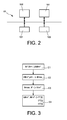
- the figure 2 represents a particular embodiment of the device according to the invention.
- the device 10 has the general structure of a computer. It comprises in particular a processor 100 executing a computer program implementing the method according to the invention, a memory 101, an input interface 102 and an output interface 103 for applying the determined values as set values of the converter.
- the input interface 102 is intended to receive the values of direct balanced current Id *, inverse balanced current Ii * and phase shift phi of the reverse current with respect to the direct current.
- the processor 100 executes the previously exposed treatments with reference to the figure 1 . These processes are performed in the form of code instructions of the computer program which are stored by the memory 101 before being executed by the processor 100.
- the memory 101 may furthermore memorize the results of the treatments carried out.
- the output interface 103 is connected to the converter to apply to it the values determined as set values.
- the current control method of a three-phase voltage converter operating in unbalanced current mode comprises the steps E1 to E4.
- Step E1 is the determination of the direct current setpoint limit value Idlim * as a function of the value of the direct balanced current Id * and the value of the current capacity of the converter Ilim.
- the Idlim direct current setpoint limit value is equal to the smallest of the current capacitance values of the Ilim converter and the Id * direct balanced current.
- the next step E2 is the determination of the maximum value of the inverse current Iimax as a function of the direct current setpoint limit value Idlim * and the phase shift phi.
- This step comprises calculating the maximum inverse current value I1max1, Iimax2 and Iimax3 for each phase according to the following formulas:
- Ii ⁇ max ⁇ 1 - id ⁇ lim * . cos phi + 1 + id ⁇ lim * . sin phi 2
- Ii ⁇ max ⁇ 2 - id ⁇ lim * . cos phi + 4. ⁇ ⁇ / 3 + 1 - id ⁇ lim * . sin phi + 4. ⁇ ⁇ / 3 2
- Ii ⁇ max ⁇ 3 - id ⁇ lim * . cos phi + 2. ⁇ ⁇ / 3 + 1 - id ⁇ lim * . sin phi + 2. ⁇ ⁇ / 3 2
- This step then comprises the determination of the minimum value among the three calculated values Iimax1, Iimax2 and Iimax3. This minimum value is the maximum value of reverse current Iimax.
- step E3 is the determination of the limit value of the reverse current command Iilim * as a function of the maximum value of the reverse current Iimax and of the value of the inverse balanced current Ii *.
- the inverse current setpoint limit value Iilim * is equal to the smallest of the values of the maximum reverse current value Iimax and the value of the inverse balanced current Ii *.
- step E4 is the determination of the values I1 * (t), I2 * (t) and I3 * (t) of the target phase currents of the converter as a function of the Idlim direct current setpoint limit value and the limit value of reverse current command Iilim *.
- I ⁇ 1 * t Idlim * . cos w . t + Iilim * . cos w . t - phi
- I ⁇ 2 * t Idlim * . cos w . t - 2. ⁇ ⁇ / 3 + Iilim * . cos w . t - phi + 2. ⁇ ⁇ / 3
- I ⁇ 3 * t Idlim * . cos w . t - 4. ⁇ ⁇ / 3 + Iilim * . cos w . t - phi + 4. ⁇ ⁇ / 3 .
Abstract
Description
La présente invention concerne de manière générale les convertisseurs triphasés de tension. Elle concerne plus particulièrement la commande des convertisseurs triphasés de tension fonctionnant en mode déséquilibré en courant.The present invention generally relates to three-phase voltage converters. It relates more particularly to the control of three-phase voltage converters operating in unbalanced current mode.
Des équipements concernés sont par exemple une alimentation triphasée avec charge déséquilibrée, une connexion côtière haute tension HVSC (d'après l'anglais High Voltage Shore Connection).Equipment concerned are, for example, a three-phase power supply with unbalanced load, a HVSC (High Voltage Shore Connection) high-voltage shore connection.
Les convertisseurs de tension, dits VSC (d'après l'anglais Voltage Source Converter) à circuit intermédiaire de tension sont commandés de sorte que le courant soit limité.The voltage converter VSCs (English Voltage Source Converter) are controlled so that the current is limited.
La limitation de courant est classiquement faite dans un cercle limite déterminé par la capacité en courant du convertisseur et défini dans un plan complexe.The current limitation is conventionally made in a limit circle determined by the current capacity of the converter and defined in a complex plane.
Or l'inventeur a constaté que la limitation du courant au cercle limite n'est pas optimale lorsque le convertisseur fonctionne en mode déséquilibré.However, the inventor has found that limiting the current to the limit circle is not optimal when the converter operates in unbalanced mode.
En effet, dans ce cas, les courants de phase du convertisseur n'atteignent pas leurs limites respectives. Cela conduit à ne pas pouvoir profiter de la pleine capacité de l'équipement. L'inventeur a constaté expérimentalement que la perte de performance peut atteindre 8 à 10 % selon l'état du déséquilibre. La perte est mesurée par l'écart entre la capacité de courant par phase et le courant crête obtenu lors de la limitation.Indeed, in this case, the phase currents of the converter do not reach their respective limits. This leads to not being able to enjoy the full capacity of the equipment. The inventor found experimentally that the loss of performance can reach 8 to 10% depending on the state of the imbalance. The loss is measured by the difference between the current capacity per phase and the peak current obtained during the limitation.
A performance constante, il faudrait sur-dimensionner l'équipement pour compenser cette perte de performance.At constant performance, the equipment should be over-sized to compensate for this loss of performance.
L'invention vise à résoudre les problèmes de la technique antérieure en fournissant un procédé de commande en courant d'un convertisseur de tension triphasé fonctionnant en mode déséquilibré en courant, caractérisé en ce qu'il comporte les étapes de :
- détermination d'une valeur limite de consigne de courant direct en fonction d'une capacité en courant du convertisseur et d'un courant équilibré direct,
- détermination d'une valeur maximale de courant inverse en fonction de la valeur limite de consigne de courant direct déterminée et telle que les courants de phase soient maximaux,
- détermination d'une valeur limite de consigne de courant inverse en fonction de la valeur maximale de courant inverse et d'un courant équilibré inverse.
- determination of a direct current setpoint limit value as a function of a current capacity of the converter and a direct balanced current,
- determination of a maximum value of reverse current as a function of the determined forward current limit value and such that the phase currents are maximum,
- determining a reverse current set point limit value as a function of the maximum reverse current value and an inverse balanced current.
Grâce à l'invention, une nouvelle condition de limitation du courant est définie pour un convertisseur triphasé de tension fonctionnant en mode déséquilibré, permettant une exploitation maximale de la capacité en courant du convertisseur.Thanks to the invention, a new condition of current limitation is defined for a three-phase voltage converter operating in unbalanced mode, allowing maximum exploitation of the current capacity of the converter.
Selon l'invention, le lieu limite du courant dans des conditions de déséquilibre n'est pas le cercle limite défini par la capacité en courant du convertisseur.According to the invention, the limit location of the current under imbalance conditions is not the limit circle defined by the current capacity of the converter.
Le courant est limité phase par phase, de manière à utiliser pleinement les possibilités en courant du convertisseur.The current is limited phase by phase, so as to make full use of the current capabilities of the converter.
Il convient de déterminer tout d'abord la valeur limite de consigne de courant direct.The direct current setpoint limit value must be determined first.
Selon une caractéristique préférée, la valeur limite de consigne de courant direct est déterminée comme étant égale à la capacité en courant du convertisseur si le courant équilibré direct a une valeur supérieure à la capacité en courant du convertisseur, et au courant équilibré direct sinon.According to a preferred characteristic, the direct current setpoint limit value is determined to be equal to the current capacity of the converter if the direct balanced current has a value greater than the current capacity of the converter, and the direct balanced current otherwise.
Une fois la valeur limite de consigne de courant direct déterminée, on travaille ensuite sur le courant inverse.Once the direct current setpoint limit value has been determined, the reverse current is then used.
Selon une autre caractéristique préférée, la valeur maximale de courant inverse est déterminée comme étant la valeur minimale de valeurs de courant maximales respectivement déterminées pour chacune des phases en fonction de la valeur limite de consigne de courant direct.According to another preferred characteristic, the maximum value of the reverse current is determined as being the minimum value of maximum current values respectively determined for each of the phases as a function of the forward current limit value.
Selon une autre caractéristique préférée, la valeur limite de consigne de courant inverse est déterminée comme étant égale à la valeur maximale de courant inverse si le courant équilibré inverse a une valeur supérieure à la valeur maximale de courant inverse, et au courant équilibré inverse sinon.According to another preferred characteristic, the inverse current setpoint limit value is determined to be equal to the maximum reverse current value if the inverse balanced current has a value greater than the maximum reverse current value, and the inverse balanced current otherwise.
Selon une autre caractéristique préféré, le procédé de commande selon l'invention comporte en outre l'étape de détermination de valeurs de courants de phase de consigne du convertisseur en fonction de la valeur limite de consigne de courant direct et de la valeur limite de consigne de courant inverse.According to another preferred characteristic, the control method according to the invention furthermore comprises the step of determining the values of the converter target phase currents as a function of the direct current setpoint limit value and the setpoint limit value. reverse current.
L'invention concerne aussi un dispositif de commande en courant d'un convertisseur de tension triphasé fonctionnant en mode déséquilibré en courant, caractérisé en ce qu'il comporte :
- des moyens de détermination d'une valeur limite de consigne de courant direct en fonction d'une capacité en courant du convertisseur et d'un courant équilibré direct,
- des moyens de détermination d'une valeur maximale de courant inverse en fonction de la valeur limite de consigne de courant direct déterminée et telle que les courants de phase soient maximaux,
- des moyens de détermination d'une valeur limite de consigne de courant inverse en fonction de la valeur maximale de courant inverse et d'un courant équilibré inverse.
- means for determining a direct current setpoint limit value as a function of a current capacity of the converter and a direct balanced current,
- means for determining a maximum value of reverse current as a function of the determined direct current setpoint limit value and such that the phase currents are maximum,
- means for determining an inverse current setpoint limit value as a function of the maximum reverse current value and an inverse balanced current.
L'invention concerne encore un convertisseur triphasé de tension, caractérisé en ce qu'il comporte un dispositif de commande tel que précédemment présenté.The invention also relates to a three-phase voltage converter, characterized in that it comprises a control device as previously presented.
Le dispositif de commande et le convertisseur présentent des avantages analogues à ceux précédemment exposés.The controller and the converter have advantages similar to those previously discussed.
Dans un mode particulier de réalisation, les étapes du procédé selon l'invention sont mises en oeuvre par des instructions de programme d'ordinateur.In a particular embodiment, the steps of the method according to the invention are implemented by computer program instructions.
En conséquence, l'invention vise aussi un programme d'ordinateur sur un support d'informations, ce programme étant susceptible d'être mis en oeuvre dans un ordinateur, ce programme comportant des instructions adaptées à la mise en oeuvre des étapes d'un procédé tel que décrit ci-dessus.Consequently, the invention also relates to a computer program on an information medium, this program being capable of being implemented in a computer, this program comprising instructions adapted to the implementation of the steps of a process as described above.
Ce programme peut utiliser n'importe quel langage de programmation, et être sous la forme de code source, code objet, ou de code intermédiaire entre code source et code objet, tel que dans une forme partiellement compilée, ou dans n'importe quelle autre forme souhaitable.This program can use any programming language, and be in the form of source code, object code, or intermediate code between source code and object code, such as in a partially compiled form, or in any other form desirable shape.
L'invention vise aussi un support d'informations lisible par un ordinateur, et comportant des instructions de programme d'ordinateur adaptées à la mise en oeuvre des étapes d'un procédé tel que décrit ci-dessus.The invention also relates to a computer readable information medium, and comprising computer program instructions adapted to the implementation of the steps of a method as described above.
Le support d'informations peut être n'importe quelle entité ou dispositif capable de stocker le programme. Par exemple, le support peut comporter un moyen de stockage, tel qu'une ROM, par exemple un CD ROM ou une ROM de circuit microélectronique, ou encore un moyen d'enregistrement magnétique, par exemple une disquette ou un disque dur.The information carrier may be any entity or device capable of storing the program. For example, the medium may comprise storage means, such as a ROM, for example a CD ROM or a microelectronic circuit ROM, or a magnetic recording means, for example a diskette or a hard disk.
D'autre part, le support d'informations peut être un support transmissible tel qu'un signal électrique ou optique, qui peut être acheminé via un câble électrique ou optique, par radio ou par d'autres moyens. Le programme selon l'invention peut être en particulier téléchargé sur un réseau de type Internet.On the other hand, the information medium may be a transmissible medium such as an electrical or optical signal, which may be conveyed via an electrical or optical cable, by radio or by others. means. The program according to the invention can be downloaded in particular on an Internet type network.
Alternativement, le support d'informations peut être un circuit intégré dans lequel le programme est incorporé, le circuit étant adapté pour exécuter ou pour être utilisé dans l'exécution du procédé selon l'invention.Alternatively, the information carrier may be an integrated circuit in which the program is incorporated, the circuit being adapted to execute or to be used in the execution of the method according to the invention.
D'autres caractéristiques et avantages apparaîtront à la lecture d'un mode de réalisation préféré donné à titre d'exemple non limitatif, décrit en référence aux figures dans lesquelles .
- La
figure 1 représente un dispositif de commande en courant d'un convertisseur de tension triphasé fonctionnant en mode déséquilibré en courant, selon l'invention, - La
figure 2 représente un mode de réalisation du dispositif selon l'invention, et - La
figure 3 représente un mode de réalisation de procédé de commande en courant d'un convertisseur de tension triphasé fonctionnant en mode déséquilibré en courant, selon l'invention.
- The
figure 1 represents a current control device of a three-phase voltage converter operating in unbalanced current mode, according to the invention, - The
figure 2 represents an embodiment of the device according to the invention, and - The
figure 3 represents a current control method embodiment of a three-phase voltage converter operating in unbalanced current mode, according to the invention.
On rappelle tout d'abord qu'il y a équivalence entre des grandeurs respectivement relatives aux phases d'un système triphasé et un vecteur d'espace qui est un nombre complexe.It is recalled first of all that there is equivalence between magnitudes respectively relative to the phases of a three-phase system and a space vector which is a complex number.
Le vecteur d'espace contient toute l'information du système triphasé original.The space vector contains all the information of the original three-phase system.
Lorsque le système triphasé est équilibré, le vecteur d'espace parcourt un cercle dans le plan complexe. Une perturbation, telle que notamment un déséquilibre, provoque une déformation du vecteur d'espace, et par conséquent du cercle, visible dans le plan complexe.When the three-phase system is balanced, the space vector travels a circle in the complex plane. A disturbance, such as in particular an imbalance, causes a deformation of the space vector, and consequently of the circle, visible in the complex plane.
Dans la suite, on s'intéresse plus particulièrement aux courants de phase d'un système triphasé déséquilibré et par conséquent au vecteur d'espace courant. Le système triphasé déséquilibré est composé de deux systèmes triphasés équilibrés dont l'un est direct et l'autre est inverse.In the following, we focus more particularly on the phase currents of an unbalanced three-phase system and consequently on the current space vector. The unbalanced three-phase system consists of two balanced three-phase systems, one of which is direct and the other is inverse.
On considère les courants de phase de référence, ou de consigne, I1*, I2* et I3* d'un convertisseur triphasé de tension. En vertu de ce qui précède, ces courants de phase de référence peuvent être exprimés en fonction d'un courant équilibré direct Id* et d'un courant équilibré inverse Ii*, selon les relations suivante :
- I1*(t) = Id*.cos(w.t) + Ii*.cos(w.t - phi)
- I2*(t) = Id*.cos(w.t - 2.n/3) + Ii*.cos(w.t - phi+2.n/3)
- I3*(t) = Id*.cos(w.t - 4.n/3) + Ii*.cos(w.t - phi + 4.π/3)
- I1 * (t) = Id * .cos (wt) + Ii * .cos (wt-phi)
- I2 * (t) = Id * .cos (wt - 2.n / 3) + Ii * .cos (wt - phi + 2.n / 3)
- I3 * (t) = Id * .cos (wt - 4.n / 3) + Ii * .cos (wt - phi + 4.π / 3)
Dans lesquelles phi est le déphasage du courant inverse par rapport au courant direct.In which phi is the phase shift of the reverse current with respect to the direct current.
Selon un mode de réalisation représenté à la
Le module 1 utilise la valeur du courant équilibré direct Id* de la manière suivante :
- Si la valeur du courant équilibré direct Id* est supérieure à la valeur de la capacité en courant du convertisseur Ilim, alors la valeur limite de consigne de courant direct Idlim* est égale à la valeur de la capacité en courant du convertisseur Ilim.
- Si la valeur du courant équilibré direct Id* est inférieure à la valeur de la capacité en courant du convertisseur Ilim, alors la valeur limite de consigne de courant direct Idlim* est égale à la valeur du courant équilibré direct Id*.
- If the value of the direct balanced current Id * is greater than the value of the current capacity of the converter Ilim, then the direct current setpoint limit value Idlim * is equal to the value of the current capacity of the converter Ilim.
- If the value of the direct balanced current Id * is smaller than the value of the current capacity of the converter Ilim, then the direct current setpoint limit value Idlim * is equal to the value of the direct balanced current Id *.
En d'autres termes, la valeur limite de consigne de courant direct Idlim* est égale à la plus petite des valeurs de la capacité en courant du convertisseur Ilim et du courant équilibré direct Id*.In other words, the direct current setpoint limit value Idlim * is equal to the smaller of the values of the current capacitance of the converter Ilim and the direct balanced current Id *.
Le module 1 comporte une interface de sortie qui est tout d'abord reliée à une interface d'entrée d'un module 2 de détermination d'une valeur maximale de courant inverse Iimax. Le module 2 comporte une seconde interface d'entrée qui est apte à recevoir le déphasage phi entre le courant direct et le courant inverse.The
Le module 1 transmet au module 2 la valeur limite de consigne de courant direct Idlim* qu'il a déterminée.
Le module 2 utilise la valeur limite de consigne de courant direct Idlim* et la valeur du déphasage phi de la manière suivante :
Le module 2 calcule tout d'abord une valeur de courant inverse maximal I1max1, Iimax2 et Iimax3 pour chaque phase, selon les formules suivantes, exprimées en unité réduite, dite « per unit » :


Le module 2 détermine ensuite la valeur minimale parmi les trois valeurs calculées Iimax1, Iimax2 et Iimax3. Cette valeur minimale est la valeur maximale de courant inverse Iimax.Le module 2 comporte une interface de sortie qui est reliée à une interfaced'entrée d'un module 3 de détermination d'une valeur limite de consigne de courant inverse Iilim* en fonction de la valeur maximale de courant inverse Iimax et du courant équilibré inverse Ii*.Le module 2 fournit la valeur maximale de courant inverseIimax au module 3.Le module 3 comporte une seconde interface d'entrée qui est apte à recevoir la valeur du courant équilibré inverse Ii*.Le module 3 utilise la valeur maximale de courant inverse Iimax et la valeur du courant équilibré inverse Ii* de la manière suivante :- Si la valeur du courant équilibré inverse Ii* est supérieure à la valeur maximale de courant inverse Iimax, alors la valeur limite de consigne de courant inverse Iilim* est égale à la valeur maximale de courant inverse Iimax.
- Si la valeur du courant équilibré inverse Ii* est inférieure à la valeur maximale de courant inverse Iimax, alors la valeur limite de consigne de courant inverse Iilim* est égale à la valeur du courant équilibré inverse Ii*.
- The
module 2 first calculates a maximum inverse current value I1max1, Iimax2 and Iimax3 for each phase, according to the following formulas, expressed in reduced unit, called "per unit": - The
module 2 then determines the minimum value among the three calculated values Iimax1, Iimax2 and Iimax3. This minimum value is the maximum value of reverse current Iimax. - The
module 2 comprises an output interface which is connected to an input interface of amodule 3 for determining a reverse current setpoint limit value Ilim * as a function of the maximum value of the reverse current Iimax and of the balanced current inverse II *.Module 2 provides the maximum value of reverse current Iimax tomodule 3. - The
module 3 comprises a second input interface which is able to receive the value of the inverse balanced current Ii *. - The
module 3 uses the maximum value of inverse current Iimax and the value of the inverse balanced current Ii * as follows:- If the value of the inverse balanced current Ii * is greater than the maximum value of the reverse current Iimax, then the set limit value of inverse current Iilim * is equal to the maximum value of reverse current Iimax.
- If the value of the inverse balanced current Ii * is smaller than the maximum value of the reverse current Iimax, then the inverse current set point limit value Ilim * is equal to the value of the inverse balanced current Ii *.
En d'autres termes, la valeur limite de consigne de courant inverse Iilim* est égale à la plus petite des valeurs parmi la valeur maximale de courant inverse Iimax et la valeur du courant équilibré inverse Ii*.In other words, the inverse current setpoint limit value Iilim * is equal to the smallest of the values of the maximum reverse current value Iimax and the value of the inverse balanced current Ii *.
Le module 3 comporte une interface de sortie qui est reliée à une interface d'entrée d'un module 4 de détermination de valeurs de courants de phase de consigne du convertisseur en fonction de la valeur limite de consigne de courant direct Idlim* et de la valeur limite de consigne de courant inverse Iilim*. Le module 3 délivre la valeur limite de consigne de courant inverse Iilim* au module 4.The
Le module 1 comporte une interface de sortie qui est reliée à une interface d'entrée du module 4. Le module 1 délivre la valeur limite de consigne de courant direct Idlim* au module 4.
Le module 4 utilise les valeurs qu'il reçoit en effectuant les calculs suivants pour déterminer les valeurs des courants de phase de consigne I1*(t), I2* (t) et I3*(t) : 


Le module 4 comporte une interface de sortie qui est reliée à une interface d'entrée d'un convertisseur de tension 5. Le module 4 délivre les valeurs des courants de phase de consigne I1*(t), I2*(t) et I3*(t) au convertisseur 5. Ce dernier est classique et ne sera pas détaillé ici.The
Le dispositif de commande, comportant essentiellement les modules 1, 2, 3 et 4 peut être intégré au convertisseur 5 ou au contraire être un dispositif extérieur associé au convertisseur 5.The control device essentially comprising the
La
Le dispositif 10 a la structure générale d'un ordinateur. Il comporte notamment un processeur 100 exécutant un programme d'ordinateur mettant en oeuvre le procédé selon l'invention, une mémoire 101, une interface d'entrée 102 et une interface de sortie 103 pour appliquer les valeurs déterminées comme valeurs de consigne du convertisseur.The
Ces différents éléments sont classiquement reliés par un bus.These different elements are conventionally connected by a bus.
L'interface d'entrée 102 est destinée à recevoir les valeurs de courant équilibré direct Id*, de courant équilibré inverse Ii* et de déphasage phi du courant inverse par rapport au courant direct.The
Le processeur 100 exécute les traitements précédemment exposés en référence à la
La mémoire 101 peut en outre mémoriser les résultats des traitements effectués.The
L'interface de sortie 103 est reliée au convertisseur pour lui appliquer les valeurs déterminées comme valeurs de consigne.The
En référence à la
L'étape E1 est la détermination de la valeur limite de consigne de courant direct Idlim* en fonction de la valeur du courant équilibré direct Id* et de la valeur de la capacité en courant du convertisseur Ilim.Step E1 is the determination of the direct current setpoint limit value Idlim * as a function of the value of the direct balanced current Id * and the value of the current capacity of the converter Ilim.
La valeur limite de consigne de courant direct Idlim* est égale à la plus petite des valeurs de la capacité en courant du convertisseur Ilim et du courant équilibré direct Id*.The Idlim direct current setpoint limit value is equal to the smallest of the current capacitance values of the Ilim converter and the Id * direct balanced current.
L'étape suivante E2 est la détermination de la valeur maximale de courant inverse Iimax en fonction de la valeur limite de consigne de courant direct Idlim* et du déphasage phi.The next step E2 is the determination of the maximum value of the inverse current Iimax as a function of the direct current setpoint limit value Idlim * and the phase shift phi.
Cette étape comporte le calcul de la valeur de courant inverse maximal I1max1, Iimax2 et Iimax3 pour chaque phase selon les formules suivantes : 
![]()
![]()
![]()
![]()
Cette étape comporte ensuite la détermination de la valeur minimale parmi les trois valeurs calculées Iimax1, Iimax2 et Iimax3. Cette valeur minimale est la valeur maximale de courant inverse Iimax.This step then comprises the determination of the minimum value among the three calculated values Iimax1, Iimax2 and Iimax3. This minimum value is the maximum value of reverse current Iimax.
L'étape suivante E3 est la détermination de la valeur limite de consigne de courant inverse Iilim* en fonction de la valeur maximale de courant inverse Iimax et de la valeur du courant équilibré inverse Ii*.The following step E3 is the determination of the limit value of the reverse current command Iilim * as a function of the maximum value of the reverse current Iimax and of the value of the inverse balanced current Ii *.
La valeur limite de consigne de courant inverse Iilim* est égale à la plus petite des valeurs parmi la valeur maximale de courant inverse Iimax et la valeur du courant équilibré inverse Ii*.The inverse current setpoint limit value Iilim * is equal to the smallest of the values of the maximum reverse current value Iimax and the value of the inverse balanced current Ii *.
L'étape suivante E4 est la détermination des valeurs I1*(t), I2*(t) et I3*(t) de courants de phase de consigne du convertisseur en fonction de la valeur limite de consigne de courant direct Idlim* et de la valeur limite de consigne de courant inverse Iilim*.The following step E4 is the determination of the values I1 * (t), I2 * (t) and I3 * (t) of the target phase currents of the converter as a function of the Idlim direct current setpoint limit value and the limit value of reverse current command Iilim *.
Ces valeurs sont déterminées selon les formules suivantes : 


Ces valeurs de courant de consigne sont ensuite appliquées au convertisseur.These setpoint current values are then applied to the converter.
Claims (9)
Priority Applications (5)
| Application Number | Priority Date | Filing Date | Title |
|---|---|---|---|
| EP13155388.5A EP2768104A1 (en) | 2013-02-15 | 2013-02-15 | Control of a three-phase voltage converter in unbalanced mode |
| CN201480006142.7A CN104956559A (en) | 2013-02-15 | 2014-02-13 | Control of a three-phase voltage converter in unbalanced mode |
| PCT/EP2014/052806 WO2014125015A2 (en) | 2013-02-15 | 2014-02-13 | Control of a three-phase voltage converter in unbalanced mode |
| CA2900813A CA2900813A1 (en) | 2013-02-15 | 2014-02-13 | Control of a three-phase voltage converter in unbalanced mode |
| US14/766,929 US20150372582A1 (en) | 2013-02-15 | 2014-02-13 | Control of a three-phase voltage converter in unbalanced mode |
Applications Claiming Priority (1)
| Application Number | Priority Date | Filing Date | Title |
|---|---|---|---|
| EP13155388.5A EP2768104A1 (en) | 2013-02-15 | 2013-02-15 | Control of a three-phase voltage converter in unbalanced mode |
Publications (1)
| Publication Number | Publication Date |
|---|---|
| EP2768104A1 true EP2768104A1 (en) | 2014-08-20 |
Family
ID=47740851
Family Applications (1)
| Application Number | Title | Priority Date | Filing Date |
|---|---|---|---|
| EP13155388.5A Withdrawn EP2768104A1 (en) | 2013-02-15 | 2013-02-15 | Control of a three-phase voltage converter in unbalanced mode |
Country Status (5)
| Country | Link |
|---|---|
| US (1) | US20150372582A1 (en) |
| EP (1) | EP2768104A1 (en) |
| CN (1) | CN104956559A (en) |
| CA (1) | CA2900813A1 (en) |
| WO (1) | WO2014125015A2 (en) |
Families Citing this family (1)
| Publication number | Priority date | Publication date | Assignee | Title |
|---|---|---|---|---|
| WO2019129729A1 (en) | 2017-12-31 | 2019-07-04 | Vito Nv | Unbalance compensation by optimally redistributing current |
Citations (3)
| Publication number | Priority date | Publication date | Assignee | Title |
|---|---|---|---|---|
| US20050063205A1 (en) * | 2003-09-24 | 2005-03-24 | Stancu Constantin C. | Method and apparatus for controlling a stand-alone 4-leg voltage source inverter |
| US20090244937A1 (en) * | 2008-03-28 | 2009-10-01 | American Superconductor Corporation | Dc bus voltage harmonics reduction |
| WO2012062327A2 (en) * | 2010-11-10 | 2012-05-18 | Vestas Wind Systems A/S | Method for operating a power generation system |
Family Cites Families (3)
| Publication number | Priority date | Publication date | Assignee | Title |
|---|---|---|---|---|
| DE102006054870A1 (en) * | 2006-11-20 | 2008-06-12 | Repower Systems Ag | Wind turbine with negative sequence control and operating procedure |
| US8559197B2 (en) * | 2008-10-13 | 2013-10-15 | Infinia Corporation | Electrical control circuits for an energy converting apparatus |
| DE102009040745A1 (en) * | 2009-09-08 | 2011-03-17 | Siemens Aktiengesellschaft | Method for controlling power converters and arrangement for carrying out the method |
-
2013
- 2013-02-15 EP EP13155388.5A patent/EP2768104A1/en not_active Withdrawn
-
2014
- 2014-02-13 US US14/766,929 patent/US20150372582A1/en not_active Abandoned
- 2014-02-13 WO PCT/EP2014/052806 patent/WO2014125015A2/en active Application Filing
- 2014-02-13 CA CA2900813A patent/CA2900813A1/en not_active Abandoned
- 2014-02-13 CN CN201480006142.7A patent/CN104956559A/en active Pending
Patent Citations (3)
| Publication number | Priority date | Publication date | Assignee | Title |
|---|---|---|---|---|
| US20050063205A1 (en) * | 2003-09-24 | 2005-03-24 | Stancu Constantin C. | Method and apparatus for controlling a stand-alone 4-leg voltage source inverter |
| US20090244937A1 (en) * | 2008-03-28 | 2009-10-01 | American Superconductor Corporation | Dc bus voltage harmonics reduction |
| WO2012062327A2 (en) * | 2010-11-10 | 2012-05-18 | Vestas Wind Systems A/S | Method for operating a power generation system |
Also Published As
| Publication number | Publication date |
|---|---|
| WO2014125015A2 (en) | 2014-08-21 |
| US20150372582A1 (en) | 2015-12-24 |
| CA2900813A1 (en) | 2014-08-21 |
| WO2014125015A3 (en) | 2014-11-13 |
| CN104956559A (en) | 2015-09-30 |
Similar Documents
| Publication | Publication Date | Title |
|---|---|---|
| EP2684289B1 (en) | Control method implemented in a power converter and intended for identifying parameters linked to the magnetic saturation of an electric motor | |
| FR3002050A1 (en) | THERMAL REGULATOR | |
| EP3001524A1 (en) | Directional detection of a ground fault in an electrical distribution network | |
| EP3080626B1 (en) | Method of estimating the residual capacities of a plurality of batteries | |
| EP2963611B1 (en) | Method for controlling electric power supplied to a power grid by at least two sources of electrical energy and associated electrical system | |
| EP2870018B1 (en) | Method for controlling a power train and corresponding system | |
| EP3229366A1 (en) | Method for controlling an asynchronous electrical motor | |
| FR3110551A1 (en) | Satellite orbital path adjustment method | |
| EP2768104A1 (en) | Control of a three-phase voltage converter in unbalanced mode | |
| EP3401694B1 (en) | Method for identifying the electrical resistance of the rotor of an electric motor | |
| EP3287795A1 (en) | Method for determining the frequency of an ac signal | |
| EP3847734B1 (en) | Method for controlling a power supply device of an electrical system | |
| EP3503380B1 (en) | Method for controlling an electric motor including an identification sequence of a transformer | |
| EP2790315A1 (en) | Rotary drive system, method for controlling an inverter, and related computer program | |
| EP1233506A9 (en) | Control method and device for a rotating electric ac machine, especially synchronous machine | |
| EP3672059B1 (en) | Adapting the deceleration of a motor as a function of an average rectified voltage | |
| EP4173130A1 (en) | Method and system for controlling a synchronous electric machine | |
| FR3072794A1 (en) | METHOD FOR DETERMINING THE PARAMETERS OF A SIMPLIFIED MODEL OF AN ENERGY STORAGE SYSTEM, A STEERING METHOD USING SUCH A MODEL AND ASSOCIATED DEVICE | |
| EP2796885B1 (en) | Method and device for determining the electric power consumed by an electric system | |
| EP3269035B1 (en) | Electrical machine torque estimator used for the vehicle electric drive and associated method | |
| EP3491731A1 (en) | Method for controlling a multi-level modular converter | |
| EP4101047B1 (en) | Method of pulse charging with variable amplitude step | |
| FR3102899A1 (en) | Three-level inverter electrical control method | |
| EP3073376A2 (en) | Method for sequencing execution commands, execution method, computer program, and integrated circuit | |
| FR3072516B1 (en) | DEVICE FOR CHARGING AN ELECTRICAL ACCUMULATION BATTERY |
Legal Events
| Date | Code | Title | Description |
|---|---|---|---|
| PUAI | Public reference made under article 153(3) epc to a published international application that has entered the european phase |
Free format text: ORIGINAL CODE: 0009012 |
|
| 17P | Request for examination filed |
Effective date: 20130215 |
|
| AK | Designated contracting states |
Kind code of ref document: A1 Designated state(s): AL AT BE BG CH CY CZ DE DK EE ES FI FR GB GR HR HU IE IS IT LI LT LU LV MC MK MT NL NO PL PT RO RS SE SI SK SM TR |
|
| AX | Request for extension of the european patent |
Extension state: BA ME |
|
| R17P | Request for examination filed (corrected) |
Effective date: 20150204 |
|
| RBV | Designated contracting states (corrected) |
Designated state(s): AL AT BE BG CH CY CZ DE DK EE ES FI FR GB GR HR HU IE IS IT LI LT LU LV MC MK MT NL NO PL PT RO RS SE SI SK SM TR |
|
| RAP1 | Party data changed (applicant data changed or rights of an application transferred) |
Owner name: GENERAL ELECTRIC TECHNOLOGY GMBH |
|
| STAA | Information on the status of an ep patent application or granted ep patent |
Free format text: STATUS: REQUEST FOR EXAMINATION WAS MADE |
|
| STAA | Information on the status of an ep patent application or granted ep patent |
Free format text: STATUS: THE APPLICATION IS DEEMED TO BE WITHDRAWN |
|
| 18D | Application deemed to be withdrawn |
Effective date: 20170901 |