EP2717409A1 - Control of a voltage adapter electronic module - Google Patents
Control of a voltage adapter electronic module Download PDFInfo
- Publication number
- EP2717409A1 EP2717409A1 EP12187122.2A EP12187122A EP2717409A1 EP 2717409 A1 EP2717409 A1 EP 2717409A1 EP 12187122 A EP12187122 A EP 12187122A EP 2717409 A1 EP2717409 A1 EP 2717409A1
- Authority
- EP
- European Patent Office
- Prior art keywords
- signal
- power
- module
- microcontroller
- converter module
- Prior art date
- Legal status (The legal status is an assumption and is not a legal conclusion. Google has not performed a legal analysis and makes no representation as to the accuracy of the status listed.)
- Withdrawn
Links
Images


Classifications
-
- H—ELECTRICITY
- H02—GENERATION; CONVERSION OR DISTRIBUTION OF ELECTRIC POWER
- H02J—CIRCUIT ARRANGEMENTS OR SYSTEMS FOR SUPPLYING OR DISTRIBUTING ELECTRIC POWER; SYSTEMS FOR STORING ELECTRIC ENERGY
- H02J3/00—Circuit arrangements for ac mains or ac distribution networks
- H02J3/38—Arrangements for parallely feeding a single network by two or more generators, converters or transformers
- H02J3/46—Controlling of the sharing of output between the generators, converters, or transformers
-
- H—ELECTRICITY
- H02—GENERATION; CONVERSION OR DISTRIBUTION OF ELECTRIC POWER
- H02J—CIRCUIT ARRANGEMENTS OR SYSTEMS FOR SUPPLYING OR DISTRIBUTING ELECTRIC POWER; SYSTEMS FOR STORING ELECTRIC ENERGY
- H02J3/00—Circuit arrangements for ac mains or ac distribution networks
- H02J3/38—Arrangements for parallely feeding a single network by two or more generators, converters or transformers
- H02J3/381—Dispersed generators
-
- H—ELECTRICITY
- H02—GENERATION; CONVERSION OR DISTRIBUTION OF ELECTRIC POWER
- H02M—APPARATUS FOR CONVERSION BETWEEN AC AND AC, BETWEEN AC AND DC, OR BETWEEN DC AND DC, AND FOR USE WITH MAINS OR SIMILAR POWER SUPPLY SYSTEMS; CONVERSION OF DC OR AC INPUT POWER INTO SURGE OUTPUT POWER; CONTROL OR REGULATION THEREOF
- H02M1/00—Details of apparatus for conversion
- H02M1/14—Arrangements for reducing ripples from dc input or output
-
- H—ELECTRICITY
- H02—GENERATION; CONVERSION OR DISTRIBUTION OF ELECTRIC POWER
- H02M—APPARATUS FOR CONVERSION BETWEEN AC AND AC, BETWEEN AC AND DC, OR BETWEEN DC AND DC, AND FOR USE WITH MAINS OR SIMILAR POWER SUPPLY SYSTEMS; CONVERSION OF DC OR AC INPUT POWER INTO SURGE OUTPUT POWER; CONTROL OR REGULATION THEREOF
- H02M7/00—Conversion of ac power input into dc power output; Conversion of dc power input into ac power output
- H02M7/42—Conversion of dc power input into ac power output without possibility of reversal
- H02M7/44—Conversion of dc power input into ac power output without possibility of reversal by static converters
- H02M7/48—Conversion of dc power input into ac power output without possibility of reversal by static converters using discharge tubes with control electrode or semiconductor devices with control electrode
- H02M7/4807—Conversion of dc power input into ac power output without possibility of reversal by static converters using discharge tubes with control electrode or semiconductor devices with control electrode having a high frequency intermediate AC stage
-
- H—ELECTRICITY
- H02—GENERATION; CONVERSION OR DISTRIBUTION OF ELECTRIC POWER
- H02J—CIRCUIT ARRANGEMENTS OR SYSTEMS FOR SUPPLYING OR DISTRIBUTING ELECTRIC POWER; SYSTEMS FOR STORING ELECTRIC ENERGY
- H02J2300/00—Systems for supplying or distributing electric power characterised by decentralized, dispersed, or local generation
- H02J2300/20—The dispersed energy generation being of renewable origin
- H02J2300/22—The renewable source being solar energy
- H02J2300/24—The renewable source being solar energy of photovoltaic origin
- H02J2300/26—The renewable source being solar energy of photovoltaic origin involving maximum power point tracking control for photovoltaic sources
-
- H—ELECTRICITY
- H02—GENERATION; CONVERSION OR DISTRIBUTION OF ELECTRIC POWER
- H02M—APPARATUS FOR CONVERSION BETWEEN AC AND AC, BETWEEN AC AND DC, OR BETWEEN DC AND DC, AND FOR USE WITH MAINS OR SIMILAR POWER SUPPLY SYSTEMS; CONVERSION OF DC OR AC INPUT POWER INTO SURGE OUTPUT POWER; CONTROL OR REGULATION THEREOF
- H02M1/00—Details of apparatus for conversion
- H02M1/0003—Details of control, feedback or regulation circuits
- H02M1/0009—Devices or circuits for detecting current in a converter
-
- H—ELECTRICITY
- H02—GENERATION; CONVERSION OR DISTRIBUTION OF ELECTRIC POWER
- H02M—APPARATUS FOR CONVERSION BETWEEN AC AND AC, BETWEEN AC AND DC, OR BETWEEN DC AND DC, AND FOR USE WITH MAINS OR SIMILAR POWER SUPPLY SYSTEMS; CONVERSION OF DC OR AC INPUT POWER INTO SURGE OUTPUT POWER; CONTROL OR REGULATION THEREOF
- H02M1/00—Details of apparatus for conversion
- H02M1/0003—Details of control, feedback or regulation circuits
- H02M1/0025—Arrangements for modifying reference values, feedback values or error values in the control loop of a converter
-
- Y—GENERAL TAGGING OF NEW TECHNOLOGICAL DEVELOPMENTS; GENERAL TAGGING OF CROSS-SECTIONAL TECHNOLOGIES SPANNING OVER SEVERAL SECTIONS OF THE IPC; TECHNICAL SUBJECTS COVERED BY FORMER USPC CROSS-REFERENCE ART COLLECTIONS [XRACs] AND DIGESTS
- Y02—TECHNOLOGIES OR APPLICATIONS FOR MITIGATION OR ADAPTATION AGAINST CLIMATE CHANGE
- Y02E—REDUCTION OF GREENHOUSE GAS [GHG] EMISSIONS, RELATED TO ENERGY GENERATION, TRANSMISSION OR DISTRIBUTION
- Y02E10/00—Energy generation through renewable energy sources
- Y02E10/50—Photovoltaic [PV] energy
- Y02E10/56—Power conversion systems, e.g. maximum power point trackers
Definitions
- An example of such electrical systems includes a power supply such as a solar panel providing a continuous signal, the output of this power supply is connected to a converter module providing a signal comprising a DC component and a sinusoidal component. This signal is sent to an inverter module which will transform this signal into a signal compatible with the network, in this case a sinusoidal signal.
- a decoupling device is installed between the power supply and the converter module.
- This decoupling means can be a capacitor of high value. This means of Decoupling prevents stray signals from the converter module or the inverter module from propagating in the power supply.
- capacitors of high value have the disadvantage of being large and expensive. Indeed, the capacitors have their price and their size which vary according to the value and the technology used.
- a value of 100 ⁇ F is a current value. This value involves a specific capacitor technology as well as a capacitor size, the latter being related to the value of said capacitor.
- electrolytic capacitors will be used.
- the invention aims to overcome the disadvantages of the prior art by proposing to provide an electronic system better matching the first signal to the second signal.
- said inverter module comprises an H-bridge.
- it further comprises a microcontroller for controlling said converter module.
- the converter module comprises at least one regulator block comprising a transformer connected in series with switching means, said switching means being controlled by said microcontroller.
- said converter module comprises at least two regulator blocks connected in parallel, the regulator blocks being controlled by pulse width modulation.
- the improvement step consists of modifying the voltage or current setpoint so that the maximum power is reached in the middle of the ripple or at the moment which gives the maximum of average power.
- the electronic system is an electrical module for adapting a first signal S I from a first system to a second signal S out of a second system
- the first system can be a power supply providing a DC voltage.
- this power supply can be one or more solar panels or one or more wind turbines or one or more batteries or others.
- the second system is for example the domestic electrical network that is to say a sinusoidal voltage.
- the DC voltage at the output of the power supply enters a converter module 102.
- This converter module comprises at least one regulator block 105.
- the converter module comprises a plurality of regulator blocks 106, 107 and 108 connected in parallel.
- the regulator block comprises a transformer T1 in series with switching means C1.
- the regulator block 105 further comprises current measuring means I1 connected in series with switching means C1.
- the transformer T1, the switching means C1 and the current measuring means I1 are connected in parallel with the first decoupling means 104.
- the regulator block 105 also comprises a rectifier R1 connected at the output of the transformer T1 to provide an intermediate signal. It is therefore clear that the regulator block 105 includes its own rectifier.
- the converter module further comprises a microcontroller 111. This microcontroller 111 is used to control the regulator block.
- the microcontroller 111 controls each regulator block 105, 106, 107 and 108 by modulation of the width. impulse. In this case, the microcontroller 111 operates a single command for all the regulator blocks. In the case where there are several power supplies 101 in parallel or in series, the control of the regulator blocks can be distinct for each block or set of blocks.
- the intermediate signal Sint is sent to an inverter module 103.
- This intermediate signal comprises a DC component S R, that is to say a continuous signal of predefined amplitude and a sinusoidal component S Q.
- This sinusoidal component is in the form of a signal in half sine or rectified sinus, ie the sinusoidal portions are all positive.
- the inverter module 103 comprises an H-bridge type circuit 104.
- This type of circuit is in the form of a plurality of switches arranged in H. It is then understood that said H-bridge comprises two parallel branches each consisting of two switches. serial. The H-bridge feeds a load which happens to be the central branch connecting the two parallel branches, this central branch is connected to each branch at the point of connection between the two switches.
- the bridge can be controlled to vary the polarity of the charging voltage cyclically to make it an inverter
- the microcontroller 111 is arranged to send control signals to the switches of the H bridge and obtain an inverter function.
- the power supply and the converter module are directly connected to each other, no device is arranged to prevent the propagation of the signals produced by the inverter module to the power supply. It will be understood that a capacitor of very low value can be placed in parallel with said power supply. This characteristic induces that the signal at the output of the power supply is a continuous signal having a ripple.
- This power output signal is then in the form of a rectified sinusoidal signal that is to say whose alternations are all positive.
- the output signal of the power supply has a frequency twice that of the second system.
- the signal of the second system is sinusoidal so that this signal has, for a period, a positive undulation and a negative undulation.
- the output signal since the output signal has a rectified appearance, it presents only positive undulations. As a result, the frequency is multiplied.
- a method for managing the operation of the micro inverter is used to adapt to this characteristic.
- the method is then configured so that the regulation and search of the maximum power point is synchronous with the output signal of the electronic system.
- the search for the maximum power point Pma is configured to have a frequency modeled on that of the output signal of the power supply.
- the converter module and the microcontroller are arranged for, alternately, to make a series of voltage and current measurements. These voltage and current measurements then make it possible to calculate a power and it is then possible to calculate the average power. This average power value is kept in a first buffer.
- a power variation is sent by the microcontroller 111.
- This setpoint or power variation command is used to initiate the regulation.
- an instruction for increasing the power is sent. This increase in power can be done by varying the current or the output voltage of the power supply.
- the microcontroller 111 understands that the maximum power has not been reached. As a result, the microcontroller will send a command or setpoint to increase the power via the current delivered by the power supply. The value of the first buffer will be erased and the value of the second buffer will be transferred to the first buffer.
- the microcontroller understands that the current delivered by the power supply is too great and therefore that the point of maximum power is exceeded.
- the microcontroller will then send a set of instructions intended to reduce the output current of the power supply.
- a new series of measurements is carried out during the next alternation giving place to the calculation of an average. This average will be compared to that of the previous alternation and so on.
- the power variation setpoint is made by varying the voltage.
- the regulation of the converter module is on a ripple. As a result, it evolves with the operation of the system.
- the power setpoint is to increase the power supplied by the power supply.
- the instantaneous power is measured at regular intervals. If it is measured that the power is only increasing, the microcontroller concludes that the maximum point of power is not reached and saves the point of highest power measured. The instruction to increase the power by changing the voltage is therefore retained and applied from the highest power point measured previously.
- the microcontroller passes in a monitoring phase. In this phase, the instantaneous power of each ripple is measured. The measurements are then compared with those of the previous ripple so that no instruction of increase or decrease of power is sent if the power variations are low.
- the step consisting in making power measurements makes it possible to know the distribution of the power and therefore to know where the maximum power points are. Knowing this, it becomes easier to modify the control of the output signal of the power supply to obtain an output signal of the power supply in which the maximum power points are ideally placed.
Abstract
Description
L'invention concerne un module électrique pour adapter un premier signal d'un premier système à un second signal d'un second système comprenant :
- une entrée agencée pour qu'une source d'alimentation puisse y être connectée, ladite source d'alimentation fournissant un premier signal, ce premier signal étant un signal continu présentant des ondulations,
- un module convertisseur agencé pour transformer la tension d'alimentation en un signal intermédiaire composé d'une composante continue et d'une composante sinusoïdale redressée;
- un module onduleur agencé pour fournir en sortie un signal compatible avec un second signal d'un second système.
- an input arranged for a power source to be connected thereto, said power source providing a first signal, said first signal being a continuous signal having ripples,
- a converter module arranged to transform the supply voltage into an intermediate signal composed of a DC component and a rectified sinusoidal component;
- an inverter module arranged to output a signal compatible with a second signal of a second system.
Il est connu des systèmes électriques dont le but est de rendre un signal compatible avec un réseau électrique. Un exemple de ces systèmes électriques comprend une alimentation électrique comme un panneau solaire fournissant un signal continu, la sortie de cette alimentation est connectée à un module convertisseur fournissant un signal comprenant une composante continue et une composante sinusoïdale. Ce signal est envoyé à un module onduleur qui va transformer ce signal en un signal compatible avec le réseau, en l'occurrence un signal sinusoïdal.It is known electrical systems whose purpose is to make a signal compatible with an electrical network. An example of such electrical systems includes a power supply such as a solar panel providing a continuous signal, the output of this power supply is connected to a converter module providing a signal comprising a DC component and a sinusoidal component. This signal is sent to an inverter module which will transform this signal into a signal compatible with the network, in this case a sinusoidal signal.
Dans les systèmes actuels, un dispositif de découplage est installé entre l'alimentation électrique et le module convertisseur. Ce moyen de découplage qui peut être un condensateur de forte valeur. Ce moyen de découplage permet d'empêcher des signaux parasites venant du module convertisseur ou du module onduleur de se propager dans l'alimentation.In current systems, a decoupling device is installed between the power supply and the converter module. This decoupling means can be a capacitor of high value. This means of Decoupling prevents stray signals from the converter module or the inverter module from propagating in the power supply.
Or, ces condensateurs de forte valeur ont l'inconvénient d'être imposants et coûteux. En effet, les condensateurs ont leur prix et leur taille qui varient selon la valeur et la technologie utilisé. Pour des condensateurs de découplage, une valeur de 100µF est une valeur courante. Cette valeur implique une technologie de condensateur spécifique ainsi qu'une taille de condensateur, cette dernière étant liée à la valeur dudit condensateur. Pour des condensateurs de découplage, on utilisera des condensateurs électrolytiques.However, these capacitors of high value have the disadvantage of being large and expensive. Indeed, the capacitors have their price and their size which vary according to the value and the technology used. For decoupling capacitors, a value of 100μF is a current value. This value involves a specific capacitor technology as well as a capacitor size, the latter being related to the value of said capacitor. For decoupling capacitors, electrolytic capacitors will be used.
L'invention a pour but de pallier les inconvénients de l'art antérieur en proposant de fournir un système électronique adaptant mieux le premier signal au second signal.The invention aims to overcome the disadvantages of the prior art by proposing to provide an electronic system better matching the first signal to the second signal.
A cet effet, l'invention concerne un module électrique pour adapter un premier signal d'un premier système à un second signal d'un second système comprenant :
- une source d'alimentation fournissant un premier signal, ce premier signal étant continu et présentant une ondulation,
- un module convertisseur agencé pour transformer la tension d'alimentation en un signal intermédiaire;
- un microcontrôleur pour commander et réguler le module convertisseur ;
- un module onduleur agencé pour fournir en sortie un signal compatible avec un second signal d'un second système,
- a power source providing a first signal, said first signal being continuous and having a ripple,
- a converter module arranged to transform the supply voltage into an intermediate signal;
- a microcontroller for controlling and regulating the converter module;
- an inverter module arranged to output a signal compatible with a second signal of a second system,
Dans un premier mode de réalisation avantageux, ledit module onduleur comprend un pont en H.In a first advantageous embodiment, said inverter module comprises an H-bridge.
Dans un second mode de réalisation avantageux, il comprend en outre un microcontrôleur permettant de contrôler ledit module convertisseur.In a second advantageous embodiment, it further comprises a microcontroller for controlling said converter module.
Dans un troisième mode de réalisation avantageux, le module convertisseur comprend au moins un bloc régulateur comprenant un transformateur connecté en série avec des moyens de commutation, lesdits moyens de commutation étant commandés par ledit microcontrôleur.In a third advantageous embodiment, the converter module comprises at least one regulator block comprising a transformer connected in series with switching means, said switching means being controlled by said microcontroller.
Dans un premier mode de réalisation avantageux, ledit module convertisseur comprend au moins deux blocs régulateurs connectés en parallèle, les blocs régulateurs étant commandé par modulation de largeur d'impulsion.In a first advantageous embodiment, said converter module comprises at least two regulator blocks connected in parallel, the regulator blocks being controlled by pulse width modulation.
L'invention concerne également un procédé de fonctionnement d'un module électrique pour adapter un premier signal d'un premier système à un second signal d'un second système, ledit module comprenant
- une source d'alimentation fournissant un premier signal, ce premier signal étant continu présentant des ondulations,
- un module convertisseur agencé pour transformer la tension d'alimentation en un signal intermédiaire;
- un microcontrôleur pour commander et réguler le module convertisseur ;
- un module onduleur agencé pour fournir en sortie un signal compatible avec un second signal d'un second système,
- a power source supplying a first signal, this first signal being continuous and presenting ripples,
- a converter module arranged to transform the supply voltage into an intermediate signal;
- a microcontroller for controlling and regulating the converter module;
- an inverter module arranged to output a signal compatible with a second signal of a second system,
Dans une premier mode de réalisation avantageux, l'étape de régulation consiste à :
- a) réaliser, durant une ondulation du premier signal, des mesures de puissances à intervalle régulier ;
- b) faire la moyenne et sauvegarder cette valeur dans une première zone mémoire
- c) comparer cette moyenne avec la moyenne des mesures de puissance réalisés lors d'une ondulation précédentes et sauvegardée dans un seconde zone mémoire :
- si la valeur de la première zone mémoire est supérieure à celle de la seconde zone mémoire, envoyer une commande d'augmentation de la consigne de la tension ou du courant du premier signal dans le but d'augmenter la puissance ;
- si la valeur de la première zone mémoire est inférieure à celle de la seconde zone mémoire, envoyer une commande de diminution de la consigne de la tension ou du courant du premier signal dans le but d'augmenter la puissance;
- sinon faire varier la consigne de la tension ou du courant du premier signal et recommencer à l'étape a)
- d) recommencer à l'étape a)
- a) performing, during a ripple of the first signal, power measurements at regular intervals;
- b) average and save this value in a first memory area
- c) comparing this average with the average of the power measurements made during a previous ripple and saved in a second memory zone:
- if the value of the first memory area is greater than that of the second memory area, sending a command to increase the setpoint of the voltage or current of the first signal in order to increase the power;
- if the value of the first memory zone is smaller than that of the second memory zone, sending a command to decrease the setpoint of the voltage or current of the first signal in order to increase the power;
- if not vary the setpoint of the voltage or current of the first signal and start again at step a)
- d) start again at step a)
Dans une second mode de réalisation avantageux, l'étape de régulation consiste à :
- A) réaliser, durant une ondulation du premier signal, des mesures de puissance instantanée à intervalle régulier ;
- B) analyser ces mesures de puissance instantanée,
- si la puissance instantanée passe par un maximum, sauvegarder dans une première zone mémoire et réaliser une étape d'amélioration.
- sinon augmenter la puissance délivrée par l'alimentation à travers le premier signal en augmentant la consigne de la tension ou du courant.
- C) recommencer à l'étape A).
- A) performing, during a ripple of the first signal, instantaneous power measurements at regular intervals;
- B) analyze these instantaneous power measurements,
- if the instantaneous power goes through a maximum, save in a first memory zone and carry out an improvement step.
- if not increase the power delivered by the power supply through the first signal by increasing the setpoint of the voltage or current.
- C) start again at step A).
Dans une troisième mode de réalisation avantageux, l'étape d'amélioration consiste à modifier la consigne de tension ou de courant de sorte que le maximum de puissance soit atteint au milieu de l'ondulation ou au moment qui donne le maximum de puissance moyenne.In a third advantageous embodiment, the improvement step consists of modifying the voltage or current setpoint so that the maximum power is reached in the middle of the ripple or at the moment which gives the maximum of average power.
Les buts, avantages et caractéristiques du module électronique et du procédé selon la présente invention apparaîtront plus clairement dans la description détaillée suivante d'au moins une forme de réalisation de l'invention donnée uniquement à titre d'exemple non limitatif et illustrée par les dessins annexés sur lesquels :
- La
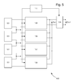
figure 1 représente schématiquement le module électronique selon l'invention - Les
figures 2 et5 représentent schématiquement chacune une variante de l'invention; et - Les
figures 3 et 4 représentent schématiquement des diagrammes de tensions du module électronique d'un premier et d'un second mode de réalisation de l'invention.
- The
figure 1 schematically represents the electronic module according to the invention - The
figures 2 and5 schematically represent each a variant of the invention; and - The
Figures 3 and 4 schematically represent voltage diagrams of the electronic module of a first and a second embodiment of the invention.
Sur la
La tension continu en sortie de l'alimentation entre dans un module convertisseur 102. Ce module convertisseur comprend au moins un bloc régulateur 105. Dans une variante visible à la
Le bloc régulateur comprend un transformateur T1 en série avec des moyens de commutation C1. Le bloc régulateur 105 comprend en outre un moyen de mesure de courant I1 monté en série des moyens de commutations C1. Le transformateur T1, les moyens de commutation C1 et le moyen de mesure de courant I1 sont montés en parallèle du premier moyen de découplage 104. Le bloc régulateur 105 comprend également un redresseur R1 connecté en sortie du transformateur T1 pour fournir un signal intermédiaire. On comprend donc que le bloc régulateur 105 comprend son propre redresseur. Le module convertisseur comprend en outre un microcontrôleur 111. Ce microcontrôleur 111 est utilisé pour commander le bloc régulateur.The regulator block comprises a transformer T1 in series with switching means C1. The
Dans le cas où le module convertisseur comprend plusieurs blocs régulateurs 105, 106, 107 et 108 en parallèle ou en série ou une combinaison parallèle et série, le microcontrôleur 111 commande chaque bloc régulateur 105, 106, 107 et 108 par modulation de largeur d'impulsion. Dans ce cas-là, le microcontrôleur 111 opère une seule commande pour tous les blocs régulateurs. Dans le cas où on a plusieurs alimentations électriques 101 en parallèle ou en série, la commande des blocs régulateurs peut être distincte pour chaque bloc ou ensemble de blocs.In the case where the converter module comprises several regulator blocks 105, 106, 107 and 108 in parallel or in series or a parallel and series combination, the
Le signal intermédiaire Sint est envoyé à un module onduleur 103. Ce signal intermédiaire comprend une composante continue SR c'est-à-dire un signal continu d'amplitude prédéfinie et une composante sinusoïdale SQ. Cette composante sinusoïdale se présente sous la forme d'un signal en demi sinus ou sinus redressé, c'est à dire que les portions sinusoïdales sont toutes positives.The intermediate signal Sint is sent to an
Le module onduleur 103 comprend un circuit de type pont en H 104. Ce type de circuit se présente sous la forme d'une pluralité de commutateurs disposé en H. on comprend alors que ledit pont en H comprend deux branches parallèles constituées chacune de deux commutateurs en série. Le pont en H alimente une charge qui se trouve être la branche centrale reliant les deux branches parallèles, cette branche centrale est connectée à chaque branche au niveau du point de connexion entre les deux commutateurs.The
Le pont peut être commandé de manière à faire varier la polarité de la tension de charge de façon cyclique pour en faire un onduleur, le microcontrôleur 111 est agencé pour envoyer des signaux de commande aux commutateurs du pont en H et obtenir une fonction onduleur.The bridge can be controlled to vary the polarity of the charging voltage cyclically to make it an inverter, the
Avantageusement selon l'invention, l'alimentation et le module convertisseur sont directement reliés l'un à l'autre, aucun dispositif de n'est agencé pour empêcher la propagation des signaux produits par le module onduleur vers l'alimentation. On comprendra alors qu'un condensateur de très faible valeur peut être placé en parallèle de ladite alimentation. Cette caractéristique induit que le signal en sortie de l'alimentation est un signal continu présentant une ondulation.Advantageously according to the invention, the power supply and the converter module are directly connected to each other, no device is arranged to prevent the propagation of the signals produced by the inverter module to the power supply. It will be understood that a capacitor of very low value can be placed in parallel with said power supply. This characteristic induces that the signal at the output of the power supply is a continuous signal having a ripple.
Ce signal de sortie de l'alimentation se présente alors sous la forme d'un signal sinusoïdal redressé c'est-à-dire dont les alternances sont toutes positives. On constatera que le signal de sortie de l'alimentation présente une fréquence double de celle du second système. Par exemple, si le second système est le réseau fonctionnant au 50Hz, le signal de sortie de l'alimentation aura une fréquence de 100Hz. En effet, le signal du second système est sinusoïdal ce qui fait que ce signal présente, pour une période, une ondulation positive et une ondulation négative. Or, comme le signal de sortie présente une allure redressée, il ne présente que des ondulations positives. Par conséquent, la fréquence est multipliée.This power output signal is then in the form of a rectified sinusoidal signal that is to say whose alternations are all positive. It will be seen that the output signal of the power supply has a frequency twice that of the second system. For example, if the second system is the network operating at 50Hz, the output signal of the power supply will have a frequency of 100Hz. Indeed, the signal of the second system is sinusoidal so that this signal has, for a period, a positive undulation and a negative undulation. However, since the output signal has a rectified appearance, it presents only positive undulations. As a result, the frequency is multiplied.
Selon l'invention, un procédé pour gérer le fonctionnement du micro onduleur est utilisé pour s'adapter à cette caractéristique. Le procédé est alors configuré pour que la régulation et recherche du point de puissance maximum soit synchrone avec le signal de sortie du système électronique.According to the invention, a method for managing the operation of the micro inverter is used to adapt to this characteristic. The method is then configured so that the regulation and search of the maximum power point is synchronous with the output signal of the electronic system.
Selon un premier mode de réalisation visible à la
Après la tout première ondulation, une variation de puissance est envoyée par le microcontrôleur 111. Cette consigne ou commande variation de puissance permet d'amorcer la régulation. Préférentiellement, une consigne d'augmentation de la puissance est envoyée. Cette augmentation de la puissance peut se faire par variation du courant ou de la tension de sortie de l'alimentation.After the very first ripple, a power variation is sent by the
Puis, pour l'alternance suivante, les mêmes actions sont réalisées c'est-à-dire que des mesures de tensions et de courants sont faites et que la moyenne de puissance est calculée et placée dans une seconde mémoire tampon. Une fois cette moyenne calculée, la valeur mesurée et celle de la première alternance sont comparées.Then, for the next alternation, the same actions are performed that is to say that measurements of voltages and currents are made and the average power is calculated and placed in a second buffer. Once this average is calculated, the measured value and the value of the first alternation are compared.
Si la moyenne de la première alternance est inférieure à la moyenne de la seconde alternance, le microcontrôleur 111 comprend que la puissance maximale n'a pas été atteinte. De ce fait, le microcontrôleur va envoyer une commande ou consigne pour augmenter la puissance via le courant délivré par l'alimentation. La valeur de la première mémoire tampon sera effacée et la valeur de la deuxième mémoire tampon sera transférée dans la première mémoire tampon.If the average of the first half-cycle is lower than the average of the second half-cycle, the
Lors de la prochaine alternance, des mesures de tension et de courant et donc de puissance seront également faites de sorte à calculer la valeur moyenne de la puissance. Cette valeur moyenne sera sauvegardé dans la seconde mémoire tampon et une étape de comparaison aura lieu.During the next alternation, voltage and current and therefore power measurements will also be made so as to calculate the average value of the power. This average value will be saved in the second buffer and a comparison step will take place.
Si la moyenne de la première alternance est supérieure à la moyenne de la seconde alternance, le microcontrôleur comprend que le courant délivré par l'alimentation est trop important et donc que le point de puissance maximale est dépassé. Le microcontrôleur va alors envoyer une consigne ayant pour but de diminuer le courant de sortie de l'alimentation. Une nouvelle série de mesures est réalisée pendant l'alternance suivante donnant lieux au calcul d'une moyenne. Cette moyenne sera comparée par rapport à celle de l'alternance précédente et ainsi de suite. Bien entendu, il est envisageable que la consigne de variation de puissance soit faite par variation de la tension.If the average of the first half-cycle is greater than the average of the second half-cycle, the microcontroller understands that the current delivered by the power supply is too great and therefore that the point of maximum power is exceeded. The microcontroller will then send a set of instructions intended to reduce the output current of the power supply. A new series of measurements is carried out during the next alternation giving place to the calculation of an average. This average will be compared to that of the previous alternation and so on. Of course, it is conceivable that the power variation setpoint is made by varying the voltage.
Dans un deuxième mode de réalisation visible à la
En effet, au démarrage du système soit dans les zones 2 de la
Pour cela, on utilise le fait que le signal de sortie de l'alimentation soit ondulé. Cette variation de la tension implique une variation de la puissance instantanée, ce qui fait qu'à chaque ondulation, la puissance instantanée peut être mesurée.For this, we use the fact that the output signal of the power supply is wavy. This variation of the voltage implies a variation of the instantaneous power, so that at each ripple, the instantaneous power can be measured.
Pendant la phase de démarrage, la consigne de puissance est d'augmenter la puissance fournie par l'alimentation. A chaque ondulation, on mesure la puissance instantanée à intervalle régulier. S'il est mesurée que la puissance ne fait qu'augmenter, le microcontrôleur en conclut que le point maximum de puissance n'est pas atteint et sauvegarde le point de puissance le plus élevé mesuré. La consigne d'augmenter la puissance par modification de la tension est donc conservé et appliqué à partir du point de puissance le plus élevé mesuré précédemment.During the start-up phase, the power setpoint is to increase the power supplied by the power supply. At each ripple, the instantaneous power is measured at regular intervals. If it is measured that the power is only increasing, the microcontroller concludes that the maximum point of power is not reached and saves the point of highest power measured. The instruction to increase the power by changing the voltage is therefore retained and applied from the highest power point measured previously.
Lors d'une ondulation, s'il est mesuré que la puissance instantanée augmente puis diminue, c'est-à-dire la zone 1, cela signifie que le point maximum de puissance est atteint et dans ce cas-là, le microcontrôleur passe dans une phase de surveillance. Dans cette phase, la puissance instantanée de chaque ondulation est mesurée. Les mesures sont alors comparées à celles de l'ondulation précédente de sorte qu'aucune consigne d'augmentation ou de diminution de puissance ne soit envoyé si les variations de puissances sont faibles.During a ripple, if it is measured that the instantaneous power increases then decreases, that is to say the zone 1, it means that the maximum power point is reached and in this case, the microcontroller passes in a monitoring phase. In this phase, the instantaneous power of each ripple is measured. The measurements are then compared with those of the previous ripple so that no instruction of increase or decrease of power is sent if the power variations are low.
Il est envisageable qu'une étape visant à améliorer le signal de sortie de l'alimentation. En effet, le fait d'atteindre le point de puissance maximum ne signifie pas que le signal de sortie de l'alimentation est parfait. Il est possible que ce signal soit déséquilibré. Effectivement, la commande du signal de sortie de l'alimentation est réalisée de sorte que le point de puissance maximum soit atteint par deux fois. Or, ce point de puissance maximum peut être atteint en début et fin de l'ondulation ou au milieu de l'ondulation.It is conceivable that a step to improve the output signal of the power supply. Indeed, reaching the maximum power point does not mean that the output signal of the power supply is perfect. It is possible that this signal is unbalanced. Effectively, the control of the output signal of the power supply is carried out so that the maximum power point is reached twice. Now this point of maximum power can be reached at the beginning and end of the undulation or in the middle of the undulation.
Par ailleurs, l'étape consistant à réaliser des mesures de puissance permet de connaitre la répartition de la puissance et donc de savoir où ce trouve les points de puissance maximum. Sachant cela, il devient plus aisé de modifier la commande du signal de sortie de l'alimentation pour obtenir un signal de sortie de l'alimentation dans lequel les points de puissance maximum sont placés idéalement.Moreover, the step consisting in making power measurements makes it possible to know the distribution of the power and therefore to know where the maximum power points are. Knowing this, it becomes easier to modify the control of the output signal of the power supply to obtain an output signal of the power supply in which the maximum power points are ideally placed.
On comprendra que diverses modifications et/ou améliorations et/ou combinaisons évidentes pour l'homme du métier peuvent être apportées aux différents modes de réalisation de l'invention exposée ci-dessus sans sortir du cadre de l'invention définie par les revendications annexées.It will be understood that various modifications and / or improvements and / or combinations obvious to those skilled in the art can be made to the various embodiments of the invention set out above without departing from the scope of the invention defined by the appended claims.
Claims (9)
caractérisé en ce que le microcontrôleur est agencé pour que la régulation du module convertisseur soit synchrone au second signal.
characterized in that the microcontroller is arranged so that the regulation of the converter module is synchronous with the second signal.
caractérisé en ce que le procédé comprend une étape de régulation visant à réguler la puissance délivrée par l'alimentation à travers le premier signal, ladite étape consistant à réaliser des mesures de puissances de manière synchrone au second système.
characterized in that the method comprises a regulating step for regulating the power delivered by the power supply through the first signal, said step of performing power measurements synchronously with the second system.
Priority Applications (8)
| Application Number | Priority Date | Filing Date | Title |
|---|---|---|---|
| EP12187122.2A EP2717409A1 (en) | 2012-10-03 | 2012-10-03 | Control of a voltage adapter electronic module |
| CN201380051480.8A CN104685751B (en) | 2012-10-03 | 2013-10-02 | The regulation of electronic voltage adaptor module |
| KR1020157011461A KR101738796B1 (en) | 2012-10-03 | 2013-10-02 | Controlling a voltage-adapting electronic module |
| EP13771158.6A EP2904683A1 (en) | 2012-10-03 | 2013-10-02 | Controlling a voltage-adapting electronic module |
| JP2015535009A JP6074045B2 (en) | 2012-10-03 | 2013-10-02 | Electronic voltage adapter module adjustment |
| US14/432,635 US11018571B2 (en) | 2012-10-03 | 2013-10-02 | Regulation of an electronic voltage adapter module |
| PCT/EP2013/070566 WO2014053557A1 (en) | 2012-10-03 | 2013-10-02 | Controlling a voltage-adapting electronic module |
| HK15108127.2A HK1207479A1 (en) | 2012-10-03 | 2015-08-21 | Controlling a voltage-adapting electronic module |
Applications Claiming Priority (1)
| Application Number | Priority Date | Filing Date | Title |
|---|---|---|---|
| EP12187122.2A EP2717409A1 (en) | 2012-10-03 | 2012-10-03 | Control of a voltage adapter electronic module |
Publications (1)
| Publication Number | Publication Date |
|---|---|
| EP2717409A1 true EP2717409A1 (en) | 2014-04-09 |
Family
ID=47071125
Family Applications (2)
| Application Number | Title | Priority Date | Filing Date |
|---|---|---|---|
| EP12187122.2A Withdrawn EP2717409A1 (en) | 2012-10-03 | 2012-10-03 | Control of a voltage adapter electronic module |
| EP13771158.6A Ceased EP2904683A1 (en) | 2012-10-03 | 2013-10-02 | Controlling a voltage-adapting electronic module |
Family Applications After (1)
| Application Number | Title | Priority Date | Filing Date |
|---|---|---|---|
| EP13771158.6A Ceased EP2904683A1 (en) | 2012-10-03 | 2013-10-02 | Controlling a voltage-adapting electronic module |
Country Status (7)
| Country | Link |
|---|---|
| US (1) | US11018571B2 (en) |
| EP (2) | EP2717409A1 (en) |
| JP (1) | JP6074045B2 (en) |
| KR (1) | KR101738796B1 (en) |
| CN (1) | CN104685751B (en) |
| HK (1) | HK1207479A1 (en) |
| WO (1) | WO2014053557A1 (en) |
Families Citing this family (5)
| Publication number | Priority date | Publication date | Assignee | Title |
|---|---|---|---|---|
| US10833629B2 (en) | 2013-03-15 | 2020-11-10 | Technology Research, Llc | Interface for renewable energy system |
| WO2017106842A1 (en) * | 2015-12-18 | 2017-06-22 | Southwire Company, Llc | Cable integrated solar inverter |
| CA3043196A1 (en) | 2016-11-07 | 2018-05-11 | Southwire Company, Llc | Dead band direct current converter |
| US11251621B1 (en) | 2017-08-03 | 2022-02-15 | Southwire Company, Llc | Solar power generation system |
| US11438988B1 (en) | 2017-08-11 | 2022-09-06 | Southwire Company, Llc | DC power management system |
Citations (1)
| Publication number | Priority date | Publication date | Assignee | Title |
|---|---|---|---|---|
| US20090179500A1 (en) * | 2008-01-10 | 2009-07-16 | Stmicroelectronics S.R.L. | Multi-cellular photovoltaic panel system with dc-dc conversion replicated for groups of cells in series of each panel and photovoltaic panel structure |
Family Cites Families (19)
| Publication number | Priority date | Publication date | Assignee | Title |
|---|---|---|---|---|
| JP2810630B2 (en) * | 1993-11-16 | 1998-10-15 | キヤノン株式会社 | Solar cell power control device, power control system, power control method, and voltage / current output characteristic measurement method |
| JP3386295B2 (en) * | 1995-08-11 | 2003-03-17 | シャープ株式会社 | Interconnected power converter |
| US5903452A (en) * | 1997-08-11 | 1999-05-11 | System General Corporation | Adaptive slope compensator for current mode power converters |
| DE19855615A1 (en) * | 1997-12-03 | 1999-06-10 | Fuji Electric Co Ltd | Switched network supply device |
| US6400582B1 (en) * | 2000-11-21 | 2002-06-04 | International Business Machines Corporation | Dual forward power converter utilizing coupling capacitors for improved efficiency |
| JP2004147465A (en) | 2002-10-25 | 2004-05-20 | Canon Inc | Converter |
| US7681090B2 (en) * | 2007-01-25 | 2010-03-16 | Solarbridge Technologies, Inc. | Ripple correlation control based on limited sampling |
| US7986539B2 (en) * | 2007-09-26 | 2011-07-26 | Enphase Energy, Inc. | Method and apparatus for maximum power point tracking in power conversion based on dual feedback loops and power ripples |
| KR101576321B1 (en) * | 2009-01-07 | 2015-12-21 | 파워-원 이태리 에스.피.에이. | Method and system for extracting electric power from a renewable energy source |
| KR101097260B1 (en) * | 2009-12-15 | 2011-12-22 | 삼성에스디아이 주식회사 | Grid-connected energy storage system and method for controlling grid-connected energy storage system |
| WO2011134058A1 (en) * | 2010-04-26 | 2011-11-03 | Queen's University At Kingston | Maximum power point tracking for a power generator |
| CN102959845B (en) * | 2010-05-10 | 2015-08-26 | 恩菲斯能源公司 | The method of operation DC-DC converter |
| US9035626B2 (en) * | 2010-08-18 | 2015-05-19 | Volterra Semiconductor Corporation | Switching circuits for extracting power from an electric power source and associated methods |
| CN101976855B (en) * | 2010-11-28 | 2013-06-19 | 河海大学常州校区 | Intelligent solar cell component and control method of array thereof |
| GB2496140B (en) * | 2011-11-01 | 2016-05-04 | Solarcity Corp | Photovoltaic power conditioning units |
| CN102122826A (en) * | 2011-01-17 | 2011-07-13 | 中国南方电网有限责任公司电网技术研究中心 | Energy storage bidirectional current converter for high-capacity storage battery |
| CN102088192B (en) * | 2011-03-02 | 2013-01-02 | 中南大学 | Single-phase single-stage current type photovoltaic grid inverter and control method thereof |
| US9071141B2 (en) * | 2011-04-08 | 2015-06-30 | Virginia Tech Intellectual Properties, Inc. | Two-stage single phase bi-directional PWM power converter with DC link capacitor reduction |
| US9143056B2 (en) * | 2011-12-16 | 2015-09-22 | Empower Micro Systems, Inc. | Stacked voltage source inverter with separate DC sources |
-
2012
- 2012-10-03 EP EP12187122.2A patent/EP2717409A1/en not_active Withdrawn
-
2013
- 2013-10-02 JP JP2015535009A patent/JP6074045B2/en active Active
- 2013-10-02 WO PCT/EP2013/070566 patent/WO2014053557A1/en active Application Filing
- 2013-10-02 CN CN201380051480.8A patent/CN104685751B/en active Active
- 2013-10-02 US US14/432,635 patent/US11018571B2/en active Active
- 2013-10-02 EP EP13771158.6A patent/EP2904683A1/en not_active Ceased
- 2013-10-02 KR KR1020157011461A patent/KR101738796B1/en active IP Right Grant
-
2015
- 2015-08-21 HK HK15108127.2A patent/HK1207479A1/en unknown
Patent Citations (1)
| Publication number | Priority date | Publication date | Assignee | Title |
|---|---|---|---|---|
| US20090179500A1 (en) * | 2008-01-10 | 2009-07-16 | Stmicroelectronics S.R.L. | Multi-cellular photovoltaic panel system with dc-dc conversion replicated for groups of cells in series of each panel and photovoltaic panel structure |
Non-Patent Citations (7)
| Title |
|---|
| ANDREAS F. BOEHRINGER: "Self-Adapting dc Converter for Solar Spacecraft Power Supply Selbstanpassender Gleichstromwandler für die Energieversorgung eines Sonnensatelliten", IEEE TRANSACTIONS ON AEROSPACE AND ELECTRONIC SYSTEMS, vol. AES-4, no. 1, 1 January 1968 (1968-01-01), pages 102 - 111, XP055053272, ISSN: 0018-9251, DOI: 10.1109/TAES.1968.5408938 * |
| BLAABJERG F ET AL: "A Review of Single-Phase Grid-Connected Inverters for Photovoltaic Modules", IEEE TRANSACTIONS ON INDUSTRY APPLICATIONS, IEEE SERVICE CENTER, PISCATAWAY, NJ, US, vol. 41, no. 5, 1 September 2005 (2005-09-01), pages 1292 - 1306, XP011139229, ISSN: 0093-9994, DOI: 10.1109/TIA.2004.841166 * |
| CHING-MING LAI ET AL: "Development of an instantaneous real power tracking control scheme for a single-phase grid-tied photovoltaic inverter with minimum DC-Link capacitance", INDUSTRIAL ELECTRONICS (ISIE), 2012 IEEE INTERNATIONAL SYMPOSIUM ON, IEEE, 28 May 2012 (2012-05-28), pages 1774 - 1779, XP032199973, ISBN: 978-1-4673-0159-6, DOI: 10.1109/ISIE.2012.6237360 * |
| ENSLIN J H R ED - INSTITUTE OF ELECTRICAL AND ELECTRONICS ENGINEERS: "Maximum power point tracking: a cost saving necessity in solar energy systems", SIGNAL PROCESSING AND SYSTEM CONTROL, FACTORY AUTOMATION. PACIFIC GROVE, NOV. 27 - 30, 1990; [PROCEEDINGS OF THE ANNUAL CONFERENCE OF THE INDUSTRIAL ELECTRONICS SOCIETY. (IECON)], NEW YORK, IEEE, US, vol. CONF. 16, 27 November 1990 (1990-11-27), pages 1073 - 1077, XP010038313, ISBN: 978-0-87942-600-2, DOI: 10.1109/IECON.1990.149286 * |
| HAIBING HU ET AL: "Power decoupling techniques for micro-inverters in PV systems-a review", ENERGY CONVERSION CONGRESS AND EXPOSITION (ECCE), 2010 IEEE, IEEE, PISCATAWAY, NJ, USA, 12 September 2010 (2010-09-12), pages 3235 - 3240, XP031787487, ISBN: 978-1-4244-5286-6 * |
| OLIVIER STALTER ET AL: "Advanced solar power electronics", POWER SEMICONDUCTOR DEVICES&IC'S (ISPSD), 2010 22ND INTERNATIONAL SYMPOSIUM ON, IEEE, PISCATAWAY, NJ, USA, 6 June 2010 (2010-06-06), pages 3 - 10, XP031729206, ISBN: 978-1-4244-7718-0 * |
| XIAO LI ET AL: "Maximum power point tracking for photovoltaic systems using adaptive extremum seeking control", DECISION AND CONTROL AND EUROPEAN CONTROL CONFERENCE (CDC-ECC), 2011 50TH IEEE CONFERENCE ON, IEEE, 12 December 2011 (2011-12-12), pages 1503 - 1508, XP032123281, ISBN: 978-1-61284-800-6, DOI: 10.1109/CDC.2011.6161436 * |
Also Published As
| Publication number | Publication date |
|---|---|
| US11018571B2 (en) | 2021-05-25 |
| HK1207479A1 (en) | 2016-01-29 |
| WO2014053557A1 (en) | 2014-04-10 |
| JP6074045B2 (en) | 2017-02-01 |
| US20150244250A1 (en) | 2015-08-27 |
| EP2904683A1 (en) | 2015-08-12 |
| CN104685751A (en) | 2015-06-03 |
| KR20150064176A (en) | 2015-06-10 |
| JP2015534440A (en) | 2015-11-26 |
| CN104685751B (en) | 2018-04-10 |
| KR101738796B1 (en) | 2017-05-22 |
Similar Documents
| Publication | Publication Date | Title |
|---|---|---|
| EP2717409A1 (en) | Control of a voltage adapter electronic module | |
| EP2697886B1 (en) | Device for charging a battery of a motor vehicle on the basis of a single-phase power supply network, and method of controlling the device | |
| FR2923653A1 (en) | OPERATING METHOD AND DEVICE FOR CONTROLLING AN ENERGY PLANT WITH PHOTOVOLTAIC MODULES. | |
| EP2842223B1 (en) | Method of controlling charge of a battery | |
| EP2577834B1 (en) | Matrix connection device for photovoltaic panels and/or wind turbines | |
| FR2801444A1 (en) | AUTONOMOUS ELECTRIC GENERATOR, ESPECIALLY FOR AIRCRAFT | |
| FR2893786A1 (en) | CONTROL METHOD AND APPARATUS FOR LIMITING THE CURRENT OF A CONTROL SYSTEM OF AN INDUCTION MACHINE | |
| EP3627687A1 (en) | Power converter | |
| FR2974257A1 (en) | POWER CONVERTER CONTROL APPARATUS | |
| EP1275196B1 (en) | Motor with phase advance angle | |
| EP3627688A1 (en) | Power converter | |
| EP3175528B1 (en) | Method and device for charging a battery of a motor vehicle depending on the impedance of a power supply network and motor vehicle provided with such a charging device | |
| CN107404237A (en) | Method and apparatus for estimating DC link capacitances | |
| EP1786090B1 (en) | Control method for poliphase inverter | |
| EP2963611A1 (en) | Method for controlling electric power supplied to a power grid by at least two sources of electrical energy and associated electrical system | |
| EP3539204B1 (en) | Method for controlling a three-phase rectifier for a charging device on board an electric or hybrid vehicle | |
| WO2019174701A2 (en) | Control of the injection of current into the power grid without a phase-locked loop, and use in relation to a wind turbine system | |
| WO2014083276A1 (en) | Method for converting alternating current into direct current and related device | |
| FR3010594A1 (en) | CONTROL METHOD IMPLEMENTED IN A SPEED DRIVE FOR DECELERATING AN ELECTRIC MOTOR | |
| EP1686682B1 (en) | Method and system for limiting the current output by a speed controller operating according to a U/F control law. | |
| WO2017187045A1 (en) | Method of controlling a dual-bridge dc/dc converter | |
| EP3520210B1 (en) | Method for controlling a three-phase rectifier for a charging device on board an electrical or hybrid vehicle | |
| FR3048830A1 (en) | METHOD AND APPARATUS FOR MONOPHASE CONTROL OF A CHARGER OF ELECTRICAL OR HYBRID TRACTION VEHICLES ONBOARD WITHOUT GALVANIC ISOLATION | |
| EP2717459A1 (en) | DC/AC converter with intermediate rectified sinusoid with offset and PWM inversion | |
| CH707569A2 (en) | Device for controlling power transmitted by power source e.g. lithium-ion-battery for charging cell phone, has feedback terminal connected with terminal of amplifier, where voltage at feedback terminal is equal to reference voltage |
Legal Events
| Date | Code | Title | Description |
|---|---|---|---|
| PUAI | Public reference made under article 153(3) epc to a published international application that has entered the european phase |
Free format text: ORIGINAL CODE: 0009012 |
|
| AK | Designated contracting states |
Kind code of ref document: A1 Designated state(s): AL AT BE BG CH CY CZ DE DK EE ES FI FR GB GR HR HU IE IS IT LI LT LU LV MC MK MT NL NO PL PT RO RS SE SI SK SM TR |
|
| AX | Request for extension of the european patent |
Extension state: BA ME |
|
| STAA | Information on the status of an ep patent application or granted ep patent |
Free format text: STATUS: THE APPLICATION IS DEEMED TO BE WITHDRAWN |
|
| 18D | Application deemed to be withdrawn |
Effective date: 20141010 |