EP2670016A2 - Apparatus for photovoltaic power generation and method thereof - Google Patents
Apparatus for photovoltaic power generation and method thereof Download PDFInfo
- Publication number
- EP2670016A2 EP2670016A2 EP13169359.0A EP13169359A EP2670016A2 EP 2670016 A2 EP2670016 A2 EP 2670016A2 EP 13169359 A EP13169359 A EP 13169359A EP 2670016 A2 EP2670016 A2 EP 2670016A2
- Authority
- EP
- European Patent Office
- Prior art keywords
- booster
- switching unit
- power generation
- output voltage
- photovoltaic power
- Prior art date
- Legal status (The legal status is an assumption and is not a legal conclusion. Google has not performed a legal analysis and makes no representation as to the accuracy of the status listed.)
- Withdrawn
Links
Images


Classifications
-
- H—ELECTRICITY
- H02—GENERATION; CONVERSION OR DISTRIBUTION OF ELECTRIC POWER
- H02J—CIRCUIT ARRANGEMENTS OR SYSTEMS FOR SUPPLYING OR DISTRIBUTING ELECTRIC POWER; SYSTEMS FOR STORING ELECTRIC ENERGY
- H02J3/00—Circuit arrangements for ac mains or ac distribution networks
- H02J3/38—Arrangements for parallely feeding a single network by two or more generators, converters or transformers
- H02J3/381—Dispersed generators
-
- H—ELECTRICITY
- H02—GENERATION; CONVERSION OR DISTRIBUTION OF ELECTRIC POWER
- H02M—APPARATUS FOR CONVERSION BETWEEN AC AND AC, BETWEEN AC AND DC, OR BETWEEN DC AND DC, AND FOR USE WITH MAINS OR SIMILAR POWER SUPPLY SYSTEMS; CONVERSION OF DC OR AC INPUT POWER INTO SURGE OUTPUT POWER; CONTROL OR REGULATION THEREOF
- H02M1/00—Details of apparatus for conversion
- H02M1/42—Circuits or arrangements for compensating for or adjusting power factor in converters or inverters
- H02M1/4208—Arrangements for improving power factor of AC input
-
- H—ELECTRICITY
- H02—GENERATION; CONVERSION OR DISTRIBUTION OF ELECTRIC POWER
- H02M—APPARATUS FOR CONVERSION BETWEEN AC AND AC, BETWEEN AC AND DC, OR BETWEEN DC AND DC, AND FOR USE WITH MAINS OR SIMILAR POWER SUPPLY SYSTEMS; CONVERSION OF DC OR AC INPUT POWER INTO SURGE OUTPUT POWER; CONTROL OR REGULATION THEREOF
- H02M3/00—Conversion of dc power input into dc power output
- H02M3/02—Conversion of dc power input into dc power output without intermediate conversion into ac
- H02M3/04—Conversion of dc power input into dc power output without intermediate conversion into ac by static converters
- H02M3/10—Conversion of dc power input into dc power output without intermediate conversion into ac by static converters using discharge tubes with control electrode or semiconductor devices with control electrode
- H02M3/145—Conversion of dc power input into dc power output without intermediate conversion into ac by static converters using discharge tubes with control electrode or semiconductor devices with control electrode using devices of a triode or transistor type requiring continuous application of a control signal
- H02M3/155—Conversion of dc power input into dc power output without intermediate conversion into ac by static converters using discharge tubes with control electrode or semiconductor devices with control electrode using devices of a triode or transistor type requiring continuous application of a control signal using semiconductor devices only
-
- H—ELECTRICITY
- H02—GENERATION; CONVERSION OR DISTRIBUTION OF ELECTRIC POWER
- H02M—APPARATUS FOR CONVERSION BETWEEN AC AND AC, BETWEEN AC AND DC, OR BETWEEN DC AND DC, AND FOR USE WITH MAINS OR SIMILAR POWER SUPPLY SYSTEMS; CONVERSION OF DC OR AC INPUT POWER INTO SURGE OUTPUT POWER; CONTROL OR REGULATION THEREOF
- H02M7/00—Conversion of ac power input into dc power output; Conversion of dc power input into ac power output
- H02M7/42—Conversion of dc power input into ac power output without possibility of reversal
- H02M7/44—Conversion of dc power input into ac power output without possibility of reversal by static converters
- H02M7/48—Conversion of dc power input into ac power output without possibility of reversal by static converters using discharge tubes with control electrode or semiconductor devices with control electrode
- H02M7/53—Conversion of dc power input into ac power output without possibility of reversal by static converters using discharge tubes with control electrode or semiconductor devices with control electrode using devices of a triode or transistor type requiring continuous application of a control signal
- H02M7/537—Conversion of dc power input into ac power output without possibility of reversal by static converters using discharge tubes with control electrode or semiconductor devices with control electrode using devices of a triode or transistor type requiring continuous application of a control signal using semiconductor devices only, e.g. single switched pulse inverters
- H02M7/5387—Conversion of dc power input into ac power output without possibility of reversal by static converters using discharge tubes with control electrode or semiconductor devices with control electrode using devices of a triode or transistor type requiring continuous application of a control signal using semiconductor devices only, e.g. single switched pulse inverters in a bridge configuration
-
- H—ELECTRICITY
- H02—GENERATION; CONVERSION OR DISTRIBUTION OF ELECTRIC POWER
- H02J—CIRCUIT ARRANGEMENTS OR SYSTEMS FOR SUPPLYING OR DISTRIBUTING ELECTRIC POWER; SYSTEMS FOR STORING ELECTRIC ENERGY
- H02J2300/00—Systems for supplying or distributing electric power characterised by decentralized, dispersed, or local generation
- H02J2300/20—The dispersed energy generation being of renewable origin
- H02J2300/22—The renewable source being solar energy
- H02J2300/24—The renewable source being solar energy of photovoltaic origin
-
- H—ELECTRICITY
- H02—GENERATION; CONVERSION OR DISTRIBUTION OF ELECTRIC POWER
- H02M—APPARATUS FOR CONVERSION BETWEEN AC AND AC, BETWEEN AC AND DC, OR BETWEEN DC AND DC, AND FOR USE WITH MAINS OR SIMILAR POWER SUPPLY SYSTEMS; CONVERSION OF DC OR AC INPUT POWER INTO SURGE OUTPUT POWER; CONTROL OR REGULATION THEREOF
- H02M1/00—Details of apparatus for conversion
- H02M1/0067—Converter structures employing plural converter units, other than for parallel operation of the units on a single load
- H02M1/0077—Plural converter units whose outputs are connected in series
-
- Y—GENERAL TAGGING OF NEW TECHNOLOGICAL DEVELOPMENTS; GENERAL TAGGING OF CROSS-SECTIONAL TECHNOLOGIES SPANNING OVER SEVERAL SECTIONS OF THE IPC; TECHNICAL SUBJECTS COVERED BY FORMER USPC CROSS-REFERENCE ART COLLECTIONS [XRACs] AND DIGESTS
- Y02—TECHNOLOGIES OR APPLICATIONS FOR MITIGATION OR ADAPTATION AGAINST CLIMATE CHANGE
- Y02E—REDUCTION OF GREENHOUSE GAS [GHG] EMISSIONS, RELATED TO ENERGY GENERATION, TRANSMISSION OR DISTRIBUTION
- Y02E10/00—Energy generation through renewable energy sources
- Y02E10/50—Photovoltaic [PV] energy
- Y02E10/56—Power conversion systems, e.g. maximum power point trackers
Definitions
- the present disclosure relates to an apparatus for photovoltaic power generation and a method thereof.
- an inverter of solar photovoltaic power generation system may be largely classified to two types, that is, a DC-DC converter (booster) transmitting DC energy of solar module (solar cell) to an inverter, and an inverter converting the DC energy to AC energy.
- the DC-DC converter is a general term that converts DC energy to DC energy, where a booster corresponds to a part of the DC-DC converter.
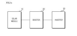
- FIG.1a is a block diagram illustrating a conventional solar photovoltaic power generation system.
- a conventional solar photovoltaic power generation system includes a solar module (10), a booster (20) and an inverter (30).
- the solar module (10) generates an electric energy using a solar light, and outputs a DC voltage corresponding to the generated electrical energy to the booster (20).
- the booster (20) increases the DC voltage outputted from the solar module to a voltage level for operating the inverter (30) and outputs the voltage of increased level to the inverter (30).
- the inverter (30) serves to convert the DC voltage outputted from the booster (20) to an AC power for transmitting to a power system.
- Drawings including FIG.1a explain exemplary embodiments of the present disclosure and only describe essential components for explaining a technical difference between the prior art and the present disclosure. A detailed circuit configuration and operation of each blocked component of the solar photovoltaic power generation system illustrated in FIG.1a will be described with reference to FIG. 1b .
- FIG.1b is a circuit diagram illustrating a detailed circuit configuration of solar photovoltaic power generation system according to prior art.
- a DC voltage outputted from the solar module (10) is charged in a capacitor (C 1 ) of the booster (20).
- the booster (20) is activated to increase (boost) the voltage to a predetermined voltage (e.g., threshold) and the increased voltage may be stored in a capacitor (C 2 ) of the inverter (30).
- a predetermined voltage e.g., threshold
- the reason of increasing, by the booster (20), the DC voltage outputted from the solar module (10) is because a DC voltage greater than a reference voltage is required for operating the inverter (30).
- the booster (20) is not operated, because the inverter (30) can be operated by itself.
- the solar photovoltaic power generation systems according to prior art as illustrated in FIGS. 1a and 1b suffer from disadvantages in that power loss is generated from an reactor (L) and a diode (D) of the booster (20) even if the booster (20) is not needed to operate.
- Exemplary aspects of the present disclosure are to substantially solve at least the above problems and/or disadvantages and to provide at least the advantages as mentioned below.
- the present disclosure is directed to provide an apparatus for photovoltaic power generation configured to improve a solar power generating efficiency of a solar photovoltaic power generation system, and a method thereof.
- an apparatus for photovoltaic power generation including a solar module, a booster and an inverter, the apparatus comprising:
- the switching unit may include at least one of a diode, a transistor and a relay circuit.
- the controller may compare the output voltage level sensed by the voltage sensing unit with a predetermined threshold, and turn on the switching unit to prevent the booster from being supplied with a power, in a case the sensed voltage level surpasses a predetermined threshold as a result of the comparison.
- the controller may turn off the switching unit to allow the booster to be supplied with a power, in a case the output voltage level sensed by the voltage sensing unit does not surpass a predetermined threshold.
- a method for photovoltaic power generation including a solar module, a booster, an inverter and a switching unit connected in parallel to the booster, the method comprising:
- the step of controlling may include comparing the sensed output voltage with the predetermined threshold; and turning on the switching unit to prevent the booster from being supplied with a power, in a case the sensed output voltage level surpasses the predetermined threshold as a result of the comparison.
- the step of comparison may further include turning off the switching unit to allow the booster to be supplied with a power, in a case the sensed output voltage level does not surpass the predetermined threshold.
- the apparatus for photovoltaic power generation and the method thereof according to the present disclosure have an advantageous effect in that a power efficiency of the apparatus can be improved by prevention of power loss caused by a reactor and a diode of a booster mounted on a conventional booster circuit, in a case the booster is inactive.
- FIG.2a is a block diagram illustrating an apparatus for photovoltaic power generation according to an exemplary embodiment of the present disclosure.
- an apparatus for photovoltaic power generation includes a solar module (100), a booster (210), a switching unit (220) connected in parallel to the booster (210), and an inverter (300).
- the solar module (100) generates an electric energy using the solar light, and outputs a DC voltage corresponding to the generated electric energy to the booster (210).
- the booster (210) boosts the DC voltage outputted from the solar module (100) to a voltage level for operating the inverter (300) and outputs the DC voltage to the inverter (300).
- the inverter (300) converts the DC voltage outputted from the booster (210) to an AC power source for transmission to an electric system.
- the switching unit (220) may be connected to the booster (210) in parallel to form two paths between the solar module (100) and the inverter (300).
- the two paths that is, a path through the booster (210) and a path through the switching unit (220), are not simultaneously used for photovoltaic power generation, and only one of the two paths may be used, if necessary.
- the apparatus for photovoltaic power generation is basically configured in such a manner that the DC power source generated by the solar module (100) is boosted by the booster (210), transmitted to the inverter (300), and converted to an AC power source for being supplied to an electric system.
- the boosting of the DC power source by the booster (210) is not always needed, such that a power loss may be generated, in a case a path is connected between the booster (210) and the inverter (300) even if there is no need of voltage boost by the booster (210).
- the switching unit (220) may be connected to the booster (210) in parallel to actually interrupt the connection with the booster (210) (or by using an equivalent circuit), in a case there is no need of voltage boost by the booster (210).
- the switching unit (220) is turned on to short-circuit a path passing the booster (210) and to allow the power source to be supplied to a path passing the switching unit (220) and simultaneously interrupt the power supply to the booster (210).
- the switching unit (220) is turned off or opened to open the path passing the switching unit (220), whereby the power source outputted to the solar module (100) is supplied only to the booster (210).
- FIG.2b is a block diagram illustrating additional elements for operation of the switching unit (220) in the apparatus for photovoltaic power generation of FIG.2a according to an exemplary embodiment of the present disclosure.
- the apparatus may further include a controller (211) and a voltage sensing unit (222) for operation of the switching unit (220).
- the apparatus may further include, in addition to the switching unit (220), a voltage sensing unit (222) for sensing an output voltage of the solar module (100), and a controller (221) for turning on and turning off the switching unit (220) in response to an output voltage level sensed by the voltage sensing unit (222).
- the switching unit (220) needs to sense an output voltage of the solar module (100) for turning on the switching unit (220), in a case there is no need of voltage boost by the booster (210), that is, in a case the output voltage level of the solar module (100) surpasses a threshold. Furthermore, the controller (221) may turn on or turn off the switching unit (220) in response to the voltage level of output of the solar module (100) sensed by the voltage sensing unit (222). That is, the controller (221) compares a size of the voltage outputted by the voltage sensing unit (222) with the threshold, and turns on or turns off the switching unit (220) in response to a comparison result.
- an electrical connection of the booster (210), the solar module (100) and the inverter (300) can be disconnected to solve the problem of power loss by a reactor (L) and a diode (D) of the booster (210).
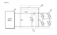
- FIG. 3a is a detailed circuit diagram illustrating the switching unit of an apparatus for photovoltaic power generation of FIGS.2a and 2b according to an exemplary embodiment of the present disclosure.
- the apparatus may include a solar module (100) configured to convert a solar energy to an electric energy, a booster (210) configured to voltage-boost an output voltage from the solar module (100), a switching unit (220) connected in parallel to the booster (210) to be turned on or turned off, and an inverter (300) configured to convert an output voltage-boosted by the booster or an output from the solar module (100) to an AC power source.
- a solar module (100) configured to convert a solar energy to an electric energy
- a booster (210) configured to voltage-boost an output voltage from the solar module (100)
- a switching unit (220) connected in parallel to the booster (210) to be turned on or turned off
- an inverter (300) configured to convert an output voltage-boosted by the booster or an output from the solar module (100) to an AC power source.
- DC energy outputted by the solar module (100) is charged in a capacitor (C 1 ) of the booster (210).
- the booster (210) is activated to increase (boost) the voltage to a predetermined voltage (e.g., threshold) and the boosted voltage may be stored in a capacitor (C 2 ) of the inverter (300).
- a predetermined voltage e.g., threshold
- the booster (210) is not operated, because the inverter (300) can be operated by itself.
- the switching unit (220) may be a general switch, and therefore, it should be apparent that any type of switch may be used as long as it can withstand a current/voltage level permitted to the apparatus for photovoltaic power generation according to an exemplary embodiment of the present disclosure.
- the switching unit (220) may be a relay circuit.
- FIG. 3b is anther detailed circuit diagram illustrating the switching unit of an apparatus for photovoltaic power generation of FIGS.2a and 2b according to an exemplary embodiment of the present disclosure.
- the switching unit (220) may be configured with a diode.
- any type of diodes may be used as long as the switching unit (220) can be turned on or turned off in response to control of the controller (221) illustrated in FIG.2b .
- the diode must be configured to rectify voltage/current level permitted to the apparatus for photovoltaic power generation according to an exemplary embodiment of the present disclosure.
Landscapes
- Engineering & Computer Science (AREA)
- Power Engineering (AREA)
- Photovoltaic Devices (AREA)
- Dc-Dc Converters (AREA)
- Inverter Devices (AREA)
Abstract
Description
- The present disclosure relates to an apparatus for photovoltaic power generation and a method thereof.
- In recent years, with emergence of serious problems such as global warming due to emission of carbon dioxide caused by use of fossil fuel and pollution with radioactivity by accidents at atomic power plants and nuclear waste, there is a growing concern about global environment and energy. Under such circumstances, particularly, solar photovoltaic power generation using solar radiation, among other new renewable energies including geothermal power generation using geothermal power and wind power generation using wind power, is being advantageously put to practical use worldwide as inexhaustible, pollution-free, noise-free and easily capacity-increasable clean energy source.
- To be more specific, an inverter of solar photovoltaic power generation system may be largely classified to two types, that is, a DC-DC converter (booster) transmitting DC energy of solar module (solar cell) to an inverter, and an inverter converting the DC energy to AC energy. The DC-DC converter is a general term that converts DC energy to DC energy, where a booster corresponds to a part of the DC-DC converter.
- Various topologies, including but not limited to, an H5 inverter and a HERIC inverter have been used to improve efficiency of inverter. Furthermore, there is a need to improve efficiency of solar photovoltaic power generation system through improvement of DC-DC converter, in addition to improvement of efficiency of inverter, and a measure is required that is capable of enhancing efficiency of photovoltaic power generation system by improving the DC-DC converter used to be applied to the existing photovoltaic power generation system.
- Hereinafter, a conventional solar photovoltaic power generation system will be described with reference to the accompanying drawings.
-
FIG.1a is a block diagram illustrating a conventional solar photovoltaic power generation system. - Referring to
FIG.1a , a conventional solar photovoltaic power generation system includes a solar module (10), a booster (20) and an inverter (30). The solar module (10) generates an electric energy using a solar light, and outputs a DC voltage corresponding to the generated electrical energy to the booster (20). The booster (20) increases the DC voltage outputted from the solar module to a voltage level for operating the inverter (30) and outputs the voltage of increased level to the inverter (30). - The inverter (30) serves to convert the DC voltage outputted from the booster (20) to an AC power for transmitting to a power system. Drawings including
FIG.1a explain exemplary embodiments of the present disclosure and only describe essential components for explaining a technical difference between the prior art and the present disclosure. A detailed circuit configuration and operation of each blocked component of the solar photovoltaic power generation system illustrated inFIG.1a will be described with reference toFIG. 1b . -
FIG.1b is a circuit diagram illustrating a detailed circuit configuration of solar photovoltaic power generation system according to prior art. - Referring to
FIG. 1b , a DC voltage outputted from the solar module (10) is charged in a capacitor (C1) of the booster (20). At this time, in a case a voltage charged in the capacitor (C1) of the booster (20) is low (e.g., in a case an output from the solar module is low due to small quantity of solar radiation as in the morning or evening), the booster (20) is activated to increase (boost) the voltage to a predetermined voltage (e.g., threshold) and the increased voltage may be stored in a capacitor (C2) of the inverter (30). - At this time, the reason of increasing, by the booster (20), the DC voltage outputted from the solar module (10) is because a DC voltage greater than a reference voltage is required for operating the inverter (30).
- Meantime, in a case a voltage outputted from the solar module (10) is a voltage sufficient enough to operate the inverter (30) (e.g., a condition where quantity of solar radiation is large as in the midday), the booster (20) is not operated, because the inverter (30) can be operated by itself.
- However, the solar photovoltaic power generation systems according to prior art as illustrated in
FIGS. 1a and1b suffer from disadvantages in that power loss is generated from an reactor (L) and a diode (D) of the booster (20) even if the booster (20) is not needed to operate. - This section provides a general summary of the disclosure, and is not a comprehensive disclosure of its full scope or all of its features.
- Exemplary aspects of the present disclosure are to substantially solve at least the above problems and/or disadvantages and to provide at least the advantages as mentioned below.
- Thus, the present disclosure is directed to provide an apparatus for photovoltaic power generation configured to improve a solar power generating efficiency of a solar photovoltaic power generation system, and a method thereof.
- Technical problems to be solved by the present disclosure are not restricted to the above-mentioned descriptions, and any other technical problems not mentioned so far will be clearly appreciated from the following description by skilled in the art.
- In one general aspect of the present invention, there is provided an apparatus for photovoltaic power generation including a solar module, a booster and an inverter, the apparatus comprising:
- a voltage sensing unit configured to sense an output voltage of the solar module; a switching unit connected to the booster in parallel; and
- a controller configured to selectively control the booster or the switching unit whereby the booster or the switching unit can be driven in response to an output voltage level sensed by the voltage sensing unit.
- Preferably, but not necessarily, the switching unit may include at least one of a diode, a transistor and a relay circuit.
- Preferably, but not necessarily, the controller may compare the output voltage level sensed by the voltage sensing unit with a predetermined threshold, and turn on the switching unit to prevent the booster from being supplied with a power, in a case the sensed voltage level surpasses a predetermined threshold as a result of the comparison.
- Preferably, but not necessarily, the controller may turn off the switching unit to allow the booster to be supplied with a power, in a case the output voltage level sensed by the voltage sensing unit does not surpass a predetermined threshold.
- In another general aspect of the present invention, there is provided a method for photovoltaic power generation including a solar module, a booster, an inverter and a switching unit connected in parallel to the booster, the method comprising:
- sensing an output voltage of the solar module; and
- selectively controlling the booster or the switching unit in response to the output voltage level sensed by a voltage sensing unit.
- Preferably, but not necessarily, the step of controlling may include comparing the sensed output voltage with the predetermined threshold; and
turning on the switching unit to prevent the booster from being supplied with a power, in a case the sensed output voltage level surpasses the predetermined threshold as a result of the comparison. - Preferably, but not necessarily, the step of comparison may further include turning off the switching unit to allow the booster to be supplied with a power, in a case the sensed output voltage level does not surpass the predetermined threshold.
- The apparatus for photovoltaic power generation and the method thereof according to the present disclosure have an advantageous effect in that a power efficiency of the apparatus can be improved by prevention of power loss caused by a reactor and a diode of a booster mounted on a conventional booster circuit, in a case the booster is inactive.
- The teachings of the present disclosure can be readily understood by considering the following detailed description in conjunction with the accompanying drawings, in which:
-
FIG.1a is a block diagram illustrating a conventional solar photovoltaic power generation system; -
FIG.1b is a circuit diagram illustrating a detailed circuit configuration of solar photovoltaic power generation system according to prior art illustrated inFIG.1a ; -
FIG.2b is a block diagram illustrating an apparatus for photovoltaic power generation according to an exemplary embodiment of the present disclosure; -
FIG.2b is a block diagram illustrating a switching unit of an apparatus for photovoltaic power generation ofFIG.2a according to an exemplary embodiment of the present disclosure; -
FIG. 3a is a detailed circuit diagram illustrating the switching unit of an apparatus for photovoltaic power generation ofFIGS.2a and2b according to an exemplary embodiment of the present disclosure; and -
FIG. 3b is anther detailed circuit diagram illustrating the switching unit of an apparatus for photovoltaic power generation ofFIGS.2a and2b according to an exemplary embodiment of the present disclosure. - Various exemplary embodiments will be described more fully hereinafter with reference to the accompanying drawings, in which some exemplary embodiments are shown. The present inventive concept may, however, be embodied in many different forms and should not be construed as limited to the example embodiments set forth herein. Rather, the described aspect is intended to embrace all such alterations, modifications, and variations that fall within the scope and novel idea of the present disclosure.
- Now, exemplary embodiments of the present disclosure will be explained in detail together with the figures.
-
FIG.2a is a block diagram illustrating an apparatus for photovoltaic power generation according to an exemplary embodiment of the present disclosure. - Referring to
FIG2a , an apparatus for photovoltaic power generation according to an exemplary embodiment of the present disclosure (hereinafter selectively referred to as 'apparatus' for simplicity) includes a solar module (100), a booster (210), a switching unit (220) connected in parallel to the booster (210), and an inverter (300). - The solar module (100) generates an electric energy using the solar light, and outputs a DC voltage corresponding to the generated electric energy to the booster (210). The booster (210) boosts the DC voltage outputted from the solar module (100) to a voltage level for operating the inverter (300) and outputs the DC voltage to the inverter (300). The inverter (300) converts the DC voltage outputted from the booster (210) to an AC power source for transmission to an electric system.
- Furthermore, the switching unit (220) may be connected to the booster (210) in parallel to form two paths between the solar module (100) and the inverter (300). The two paths, that is, a path through the booster (210) and a path through the switching unit (220), are not simultaneously used for photovoltaic power generation, and only one of the two paths may be used, if necessary.
- The apparatus for photovoltaic power generation according to an exemplary embodiment of the present disclosure is basically configured in such a manner that the DC power source generated by the solar module (100) is boosted by the booster (210), transmitted to the inverter (300), and converted to an AC power source for being supplied to an electric system.
- However, the boosting of the DC power source by the booster (210) is not always needed, such that a power loss may be generated, in a case a path is connected between the booster (210) and the inverter (300) even if there is no need of voltage boost by the booster (210).
- Hence, in the exemplary embodiment of the present disclosure, the switching unit (220) may be connected to the booster (210) in parallel to actually interrupt the connection with the booster (210) (or by using an equivalent circuit), in a case there is no need of voltage boost by the booster (210). In other words, the switching unit (220) is turned on to short-circuit a path passing the booster (210) and to allow the power source to be supplied to a path passing the switching unit (220) and simultaneously interrupt the power supply to the booster (210).
- Meanwhile, in a case there is a need of a voltage boost by the booster (210), the switching unit (220) is turned off or opened to open the path passing the switching unit (220), whereby the power source outputted to the solar module (100) is supplied only to the booster (210).
-
FIG.2b is a block diagram illustrating additional elements for operation of the switching unit (220) in the apparatus for photovoltaic power generation ofFIG.2a according to an exemplary embodiment of the present disclosure. Referring toFIG.2b , the apparatus may further include a controller (211) and a voltage sensing unit (222) for operation of the switching unit (220). - That is, the apparatus may further include, in addition to the switching unit (220), a voltage sensing unit (222) for sensing an output voltage of the solar module (100), and a controller (221) for turning on and turning off the switching unit (220) in response to an output voltage level sensed by the voltage sensing unit (222).
- The switching unit (220) needs to sense an output voltage of the solar module (100) for turning on the switching unit (220), in a case there is no need of voltage boost by the booster (210), that is, in a case the output voltage level of the solar module (100) surpasses a threshold.
Furthermore, the controller (221) may turn on or turn off the switching unit (220) in response to the voltage level of output of the solar module (100) sensed by the voltage sensing unit (222). That is, the controller (221) compares a size of the voltage outputted by the voltage sensing unit (222) with the threshold, and turns on or turns off the switching unit (220) in response to a comparison result. - Based on the above operation, in a case there is no need of operating the booster (210), an electrical connection of the booster (210), the solar module (100) and the inverter (300) can be disconnected to solve the problem of power loss by a reactor (L) and a diode (D) of the booster (210).
-
FIG. 3a is a detailed circuit diagram illustrating the switching unit of an apparatus for photovoltaic power generation ofFIGS.2a and2b according to an exemplary embodiment of the present disclosure. - Referring to
FIG. 3a , the apparatus may include a solar module (100) configured to convert a solar energy to an electric energy, a booster (210) configured to voltage-boost an output voltage from the solar module (100), a switching unit (220) connected in parallel to the booster (210) to be turned on or turned off, and an inverter (300) configured to convert an output voltage-boosted by the booster or an output from the solar module (100) to an AC power source. - Now, an operation of configuration illustrated in
FIG.3a will be briefly explained. DC energy outputted by the solar module (100) is charged in a capacitor (C1) of the booster (210). At this time, in a case a voltage charged in the capacitor (C1) of the booster (210) is low (e.g., in a case an output from the solar module is low due to small quantity of solar radiation as in the morning or evening), the booster (210) is activated to increase (boost) the voltage to a predetermined voltage (e.g., threshold) and the boosted voltage may be stored in a capacitor (C2) of the inverter (300). At this time, in a case a voltage outputted from the solar module (100) is a voltage sufficient enough to operate the inverter (300) (e.g., a condition where quantity of solar radiation is large as in the midday), the booster (210) is not operated, because the inverter (300) can be operated by itself. - Thus, selective operation by the booster (210) allows the switching unit (220) to be included in the apparatus for photovoltaic power generation according to an exemplary embodiment of the present disclosure. As illustrated in
FIG.3a , the switching unit (220) may be a general switch, and therefore, it should be apparent that any type of switch may be used as long as it can withstand a current/voltage level permitted to the apparatus for photovoltaic power generation according to an exemplary embodiment of the present disclosure. Thus, the switching unit (220) may be a relay circuit. -
FIG. 3b is anther detailed circuit diagram illustrating the switching unit of an apparatus for photovoltaic power generation ofFIGS.2a and2b according to an exemplary embodiment of the present disclosure. - Referring to
FIG.3b , the switching unit (220) may be configured with a diode. Thus, it should be apparent that any type of diodes may be used as long as the switching unit (220) can be turned on or turned off in response to control of the controller (221) illustrated inFIG.2b . Furthermore, the diode must be configured to rectify voltage/current level permitted to the apparatus for photovoltaic power generation according to an exemplary embodiment of the present disclosure. - The above-mentioned apparatus and method for photovoltaic power generation according to the exemplary embodiment of the present disclosure may, however, be embodied in many different forms and should not be construed as limited to the embodiment set forth herein. Thus, it is intended that embodiment of the present disclosure may cover the modifications and variations of this disclosure provided they come within the scope of the appended claims and their equivalents. While particular features or aspects may have been disclosed with respect to several embodiments, such features or aspects may be selectively combined with one or more other features and/or aspects of other embodiments as may be desired.
Claims (7)
- An apparatus for photovoltaic power generation including a solar module (100), a booster (210) and an inverter (300), the apparatus characterized by:a voltage sensing unit (222) configured to sense an output voltage of the solar module (100); a switching unit (220) connected to the booster (210) in parallel;
anda controller (221) configured to selectively control the booster (210) or the switching unit (220) whereby the booster (210) or the switching unit (220) can be driven in response to an output voltage level sensed by the voltage sensing unit (222). - The apparatus of claim 1, wherein the switching unit (220) includes at least one of a diode, a transistor and a relay circuit.
- The apparatus of claim 1, wherein the controller (221) compares the output voltage level sensed by the voltage sensing unit (222) with a predetermined threshold, and turns on the switching unit (220) to prevent the booster (210) from being supplied with a power, in a case the sensed voltage level surpasses a predetermined threshold as a result of the comparison.
- The apparatus of claim 3, wherein the controller (221) turns off the switching unit to allow the booster to be supplied with a power, in a case the output voltage level sensed by the voltage sensing unit (222) does not surpass a predetermined threshold.
- A method for photovoltaic power generation including a solar module (100), a booster (210), an inverter (300) and a switching unit (220) connected in parallel to the booster (210), the method comprising:sensing an output voltage of the solar module (100); andselectively controlling the booster (210) or the switching unit (220) in response to the output voltage level sensed by a voltage sensing unit (222).
- The method of claim 5, wherein the step of controlling includes comparing the sensed output voltage with the predetermined threshold; and
turning on the switching unit (220) to prevent the booster (210) from being supplied with a power, in a case the sensed output voltage level surpasses the predetermined threshold as a result of the comparison. - The method of claim 6, wherein the step of comparison further includes turning off the switching unit (220) to allow the booster (210) to be supplied with a power, in a case the sensed output voltage level does not surpass the predetermined threshold.
Applications Claiming Priority (1)
| Application Number | Priority Date | Filing Date | Title |
|---|---|---|---|
| KR1020120056634A KR20130133413A (en) | 2012-05-29 | 2012-05-29 | An apparatus for photovoltaic power generation |
Publications (2)
| Publication Number | Publication Date |
|---|---|
| EP2670016A2 true EP2670016A2 (en) | 2013-12-04 |
| EP2670016A3 EP2670016A3 (en) | 2014-06-25 |
Family
ID=48625737
Family Applications (1)
| Application Number | Title | Priority Date | Filing Date |
|---|---|---|---|
| EP13169359.0A Withdrawn EP2670016A3 (en) | 2012-05-29 | 2013-05-27 | Apparatus for photovoltaic power generation and method thereof |
Country Status (5)
| Country | Link |
|---|---|
| US (1) | US20130322140A1 (en) |
| EP (1) | EP2670016A3 (en) |
| JP (1) | JP2013247370A (en) |
| KR (1) | KR20130133413A (en) |
| CN (1) | CN103457511A (en) |
Cited By (4)
| Publication number | Priority date | Publication date | Assignee | Title |
|---|---|---|---|---|
| WO2017194598A1 (en) * | 2016-05-13 | 2017-11-16 | Phoenix Contact Gmbh & Co Kg | Voltage transformer having a reverse polarity protection diode |
| EP3216992B1 (en) | 2016-03-10 | 2018-10-31 | Eberspächer Exhaust Technology GmbH & Co. KG | Mixer |
| EP3547527A1 (en) * | 2018-03-28 | 2019-10-02 | Sungrow Power Supply Co., Ltd. | Medium-high voltage photovoltaic power generation system |
| EP3699018A1 (en) * | 2019-02-21 | 2020-08-26 | Audi AG | Drive device and method for operating a drive device |
Families Citing this family (8)
| Publication number | Priority date | Publication date | Assignee | Title |
|---|---|---|---|---|
| JP6349974B2 (en) * | 2014-05-30 | 2018-07-04 | 住友電気工業株式会社 | Conversion device |
| CN105119321A (en) * | 2015-09-29 | 2015-12-02 | 广西比迪光电科技工程有限责任公司 | System capable of increasing generating capacity of photovoltaic power generation system |
| WO2018212520A1 (en) | 2017-05-17 | 2018-11-22 | Samsung Electronics Co., Ltd. | Electronic device for harvesting power from at least one power source and method for operating the same |
| KR102555171B1 (en) * | 2017-05-17 | 2023-07-13 | 삼성전자주식회사 | Electronic device for harvesting power from at least one power source and operation method thereof |
| US11223208B2 (en) | 2017-08-21 | 2022-01-11 | General Electric Company | Method and system for controlling integration of DC power source in hybrid power generation system |
| KR102412303B1 (en) | 2021-07-30 | 2022-06-23 | 주식회사 스마트파워 | String optima for tracking equal voltage in string units using current value, and solar power generation system using the same |
| KR102242814B1 (en) | 2020-12-31 | 2021-04-21 | 주식회사 엘파워 | String-optima having possible output optimal equal voltage |
| KR20240057701A (en) * | 2022-10-25 | 2024-05-03 | 주식회사 윌링스 | Solar Power Inverter with Boost Converter and the Control Method |
Family Cites Families (12)
| Publication number | Priority date | Publication date | Assignee | Title |
|---|---|---|---|---|
| JPH05137267A (en) * | 1991-11-12 | 1993-06-01 | Dia Semikon Syst Kk | Power system |
| JPH1146457A (en) * | 1997-07-25 | 1999-02-16 | Tdk Corp | Charging device utilizing solar cell |
| JP2000112545A (en) * | 1998-09-30 | 2000-04-21 | Daihen Corp | Photovoltaic power generation system |
| JP2000174308A (en) * | 1998-12-01 | 2000-06-23 | Toshiba Corp | Solar battery power generation module |
| US6801028B2 (en) * | 2002-11-14 | 2004-10-05 | Fyre Storm, Inc. | Phase locked looped based digital pulse converter |
| EP1706936A1 (en) * | 2004-01-09 | 2006-10-04 | Philips Intellectual Property & Standards GmbH | Decentralized power generation system |
| JP4520325B2 (en) * | 2005-02-25 | 2010-08-04 | 三菱電機株式会社 | Power converter |
| JP4468840B2 (en) * | 2005-02-25 | 2010-05-26 | 三菱電機株式会社 | Power converter |
| WO2006090672A1 (en) * | 2005-02-25 | 2006-08-31 | Mitsubishi Denki Kabushiki Kaisha | Power converter |
| DE102008004675B3 (en) * | 2007-10-12 | 2009-03-05 | Fraunhofer-Gesellschaft zur Förderung der angewandten Forschung e.V. | Controllable switching device for solar module, has control provided to control controllable switching unit to switch switching unit in one of switch conditions using output of solar module or input at output terminal |
| US8184460B2 (en) * | 2009-05-28 | 2012-05-22 | General Electric Company | Solar inverter and control method |
| JP4631995B1 (en) * | 2010-06-18 | 2011-02-23 | オムロン株式会社 | Voltage setting device, photovoltaic power generation system, and voltage setting device control method |
-
2012
- 2012-05-29 KR KR1020120056634A patent/KR20130133413A/en not_active Application Discontinuation
-
2013
- 2013-05-22 US US13/900,249 patent/US20130322140A1/en not_active Abandoned
- 2013-05-27 EP EP13169359.0A patent/EP2670016A3/en not_active Withdrawn
- 2013-05-28 JP JP2013111990A patent/JP2013247370A/en active Pending
- 2013-05-29 CN CN2013102067726A patent/CN103457511A/en active Pending
Non-Patent Citations (1)
| Title |
|---|
| None |
Cited By (7)
| Publication number | Priority date | Publication date | Assignee | Title |
|---|---|---|---|---|
| EP3216992B1 (en) | 2016-03-10 | 2018-10-31 | Eberspächer Exhaust Technology GmbH & Co. KG | Mixer |
| WO2017194598A1 (en) * | 2016-05-13 | 2017-11-16 | Phoenix Contact Gmbh & Co Kg | Voltage transformer having a reverse polarity protection diode |
| US10511166B2 (en) | 2016-05-13 | 2019-12-17 | Phoenix Contact Gmbh & Co Kg | Voltage converter having a reverse polarity protection diode |
| EP3547527A1 (en) * | 2018-03-28 | 2019-10-02 | Sungrow Power Supply Co., Ltd. | Medium-high voltage photovoltaic power generation system |
| US10938208B2 (en) | 2018-03-28 | 2021-03-02 | Sungrow Power Supply Co., Ltd. | Medium-high voltage photovoltaic power generation system |
| EP3699018A1 (en) * | 2019-02-21 | 2020-08-26 | Audi AG | Drive device and method for operating a drive device |
| US11031889B2 (en) | 2019-02-21 | 2021-06-08 | Audi Ag | Drive device and method for operating a drive device |
Also Published As
| Publication number | Publication date |
|---|---|
| US20130322140A1 (en) | 2013-12-05 |
| JP2013247370A (en) | 2013-12-09 |
| EP2670016A3 (en) | 2014-06-25 |
| CN103457511A (en) | 2013-12-18 |
| KR20130133413A (en) | 2013-12-09 |
Similar Documents
| Publication | Publication Date | Title |
|---|---|---|
| EP2670016A2 (en) | Apparatus for photovoltaic power generation and method thereof | |
| JP5208374B2 (en) | Grid interconnection power conditioner and grid interconnection power system | |
| JP5124114B2 (en) | Power conditioner with power storage function | |
| EP2232663B2 (en) | Safety mechanisms, wake up and shutdown methods in distributed power installations | |
| JP5344759B2 (en) | Power distribution system | |
| JP5246239B2 (en) | Power supply | |
| KR101830666B1 (en) | Power conversion apparatus | |
| KR101214676B1 (en) | Electric generating system using solar cell | |
| JP3796460B2 (en) | Power conditioner for photovoltaic system | |
| KR20160129265A (en) | Grid connected power apparatus using solar converter and energy storage converter | |
| KR100702223B1 (en) | solar photovoltaic system and method | |
| KR20070009497A (en) | Solar generating apparatus with a separating direct current generating module and managing system of the same | |
| JP5211772B2 (en) | Power conditioner operation control device and photovoltaic power generation system | |
| JP2009207234A (en) | Linkage system of hybrid system | |
| KR101130320B1 (en) | Standby power supply system for wind turbine system | |
| KR101426696B1 (en) | Grid-connected module type photovoltaic power conversion apparatus | |
| KR20080030129A (en) | Solar energy power generation system | |
| KR101764651B1 (en) | Power applying apparatus and method for controlling connecting photovoltaic power generating apparatus | |
| KR101878669B1 (en) | Photovoltaic power generating apparatus and controlling method of the same in grid-connected system | |
| KR20160129266A (en) | Grid connected power apparatus using solar converter, energy storage converter and wind converter | |
| KR101376550B1 (en) | High Capacity Wind-Power Generator, Method for Controlling High Capacity Wind-Power Generator | |
| JP5931345B2 (en) | Uninterruptible power supply system | |
| JP2015133870A (en) | Power converter and power conversion method | |
| JP2005312158A (en) | Power converter and its control method, and solarlight power generator | |
| JP5895143B2 (en) | Power storage device |
Legal Events
| Date | Code | Title | Description |
|---|---|---|---|
| PUAI | Public reference made under article 153(3) epc to a published international application that has entered the european phase |
Free format text: ORIGINAL CODE: 0009012 |
|
| AK | Designated contracting states |
Kind code of ref document: A2 Designated state(s): AL AT BE BG CH CY CZ DE DK EE ES FI FR GB GR HR HU IE IS IT LI LT LU LV MC MK MT NL NO PL PT RO RS SE SI SK SM TR |
|
| AX | Request for extension of the european patent |
Extension state: BA ME |
|
| PUAL | Search report despatched |
Free format text: ORIGINAL CODE: 0009013 |
|
| AK | Designated contracting states |
Kind code of ref document: A3 Designated state(s): AL AT BE BG CH CY CZ DE DK EE ES FI FR GB GR HR HU IE IS IT LI LT LU LV MC MK MT NL NO PL PT RO RS SE SI SK SM TR |
|
| AX | Request for extension of the european patent |
Extension state: BA ME |
|
| RIC1 | Information provided on ipc code assigned before grant |
Ipc: H02J 3/38 20060101AFI20140520BHEP Ipc: H02M 3/155 20060101ALI20140520BHEP |
|
| 17P | Request for examination filed |
Effective date: 20150105 |
|
| RBV | Designated contracting states (corrected) |
Designated state(s): AL AT BE BG CH CY CZ DE DK EE ES FI FR GB GR HR HU IE IS IT LI LT LU LV MC MK MT NL NO PL PT RO RS SE SI SK SM TR |
|
| 17Q | First examination report despatched |
Effective date: 20180612 |
|
| STAA | Information on the status of an ep patent application or granted ep patent |
Free format text: STATUS: THE APPLICATION HAS BEEN WITHDRAWN |
|
| 18W | Application withdrawn |
Effective date: 20181019 |