EP2658112B1 - Methods and Systems for Controlling a Power Converter - Google Patents
Methods and Systems for Controlling a Power Converter Download PDFInfo
- Publication number
- EP2658112B1 EP2658112B1 EP13164778.6A EP13164778A EP2658112B1 EP 2658112 B1 EP2658112 B1 EP 2658112B1 EP 13164778 A EP13164778 A EP 13164778A EP 2658112 B1 EP2658112 B1 EP 2658112B1
- Authority
- EP
- European Patent Office
- Prior art keywords
- regulator
- power
- signal
- oscillations
- converter
- Prior art date
- Legal status (The legal status is an assumption and is not a legal conclusion. Google has not performed a legal analysis and makes no representation as to the accuracy of the status listed.)
- Active
Links
- 238000000034 method Methods 0.000 title description 19
- 230000010355 oscillation Effects 0.000 claims description 65
- 239000003381 stabilizer Substances 0.000 claims description 58
- 230000006641 stabilisation Effects 0.000 claims description 53
- 238000011105 stabilization Methods 0.000 claims description 53
- 238000006243 chemical reaction Methods 0.000 claims description 40
- 238000012546 transfer Methods 0.000 claims description 18
- 238000010248 power generation Methods 0.000 description 47
- 230000006870 function Effects 0.000 description 25
- 238000010586 diagram Methods 0.000 description 12
- 238000011084 recovery Methods 0.000 description 9
- 230000005611 electricity Effects 0.000 description 6
- 230000009467 reduction Effects 0.000 description 6
- 230000005540 biological transmission Effects 0.000 description 5
- 238000005259 measurement Methods 0.000 description 4
- 238000012544 monitoring process Methods 0.000 description 4
- 230000001419 dependent effect Effects 0.000 description 3
- 239000000446 fuel Substances 0.000 description 3
- 230000015654 memory Effects 0.000 description 3
- 238000003491 array Methods 0.000 description 2
- 238000004364 calculation method Methods 0.000 description 2
- 238000001514 detection method Methods 0.000 description 2
- 230000000694 effects Effects 0.000 description 2
- 239000012530 fluid Substances 0.000 description 2
- 230000006698 induction Effects 0.000 description 2
- 230000002093 peripheral effect Effects 0.000 description 2
- 230000008569 process Effects 0.000 description 2
- 230000004044 response Effects 0.000 description 2
- 230000003068 static effect Effects 0.000 description 2
- 230000001360 synchronised effect Effects 0.000 description 2
- 230000033228 biological regulation Effects 0.000 description 1
- 238000004891 communication Methods 0.000 description 1
- 230000009977 dual effect Effects 0.000 description 1
- 238000001914 filtration Methods 0.000 description 1
- 238000010304 firing Methods 0.000 description 1
- 239000002803 fossil fuel Substances 0.000 description 1
- 230000003534 oscillatory effect Effects 0.000 description 1
- 238000012545 processing Methods 0.000 description 1
- 238000004088 simulation Methods 0.000 description 1
- 230000000087 stabilizing effect Effects 0.000 description 1
- 238000012360 testing method Methods 0.000 description 1
- 230000001052 transient effect Effects 0.000 description 1
- XLYOFNOQVPJJNP-UHFFFAOYSA-N water Substances O XLYOFNOQVPJJNP-UHFFFAOYSA-N 0.000 description 1
Images


Classifications
-
- H—ELECTRICITY
- H02—GENERATION; CONVERSION OR DISTRIBUTION OF ELECTRIC POWER
- H02P—CONTROL OR REGULATION OF ELECTRIC MOTORS, ELECTRIC GENERATORS OR DYNAMO-ELECTRIC CONVERTERS; CONTROLLING TRANSFORMERS, REACTORS OR CHOKE COILS
- H02P9/00—Arrangements for controlling electric generators for the purpose of obtaining a desired output
-
- F—MECHANICAL ENGINEERING; LIGHTING; HEATING; WEAPONS; BLASTING
- F03—MACHINES OR ENGINES FOR LIQUIDS; WIND, SPRING, OR WEIGHT MOTORS; PRODUCING MECHANICAL POWER OR A REACTIVE PROPULSIVE THRUST, NOT OTHERWISE PROVIDED FOR
- F03D—WIND MOTORS
- F03D7/00—Controlling wind motors
- F03D7/02—Controlling wind motors the wind motors having rotation axis substantially parallel to the air flow entering the rotor
- F03D7/028—Controlling wind motors the wind motors having rotation axis substantially parallel to the air flow entering the rotor controlling wind motor output power
- F03D7/0284—Controlling wind motors the wind motors having rotation axis substantially parallel to the air flow entering the rotor controlling wind motor output power in relation to the state of the electric grid
-
- H—ELECTRICITY
- H02—GENERATION; CONVERSION OR DISTRIBUTION OF ELECTRIC POWER
- H02J—CIRCUIT ARRANGEMENTS OR SYSTEMS FOR SUPPLYING OR DISTRIBUTING ELECTRIC POWER; SYSTEMS FOR STORING ELECTRIC ENERGY
- H02J3/00—Circuit arrangements for ac mains or ac distribution networks
- H02J3/24—Arrangements for preventing or reducing oscillations of power in networks
-
- H—ELECTRICITY
- H02—GENERATION; CONVERSION OR DISTRIBUTION OF ELECTRIC POWER
- H02P—CONTROL OR REGULATION OF ELECTRIC MOTORS, ELECTRIC GENERATORS OR DYNAMO-ELECTRIC CONVERTERS; CONTROLLING TRANSFORMERS, REACTORS OR CHOKE COILS
- H02P21/00—Arrangements or methods for the control of electric machines by vector control, e.g. by control of field orientation
- H02P21/05—Arrangements or methods for the control of electric machines by vector control, e.g. by control of field orientation specially adapted for damping motor oscillations, e.g. for reducing hunting
-
- H—ELECTRICITY
- H02—GENERATION; CONVERSION OR DISTRIBUTION OF ELECTRIC POWER
- H02P—CONTROL OR REGULATION OF ELECTRIC MOTORS, ELECTRIC GENERATORS OR DYNAMO-ELECTRIC CONVERTERS; CONTROLLING TRANSFORMERS, REACTORS OR CHOKE COILS
- H02P9/00—Arrangements for controlling electric generators for the purpose of obtaining a desired output
- H02P9/10—Control effected upon generator excitation circuit to reduce harmful effects of overloads or transients, e.g. sudden application of load, sudden removal of load, sudden change of load
-
- H—ELECTRICITY
- H03—ELECTRONIC CIRCUITRY
- H03L—AUTOMATIC CONTROL, STARTING, SYNCHRONISATION, OR STABILISATION OF GENERATORS OF ELECTRONIC OSCILLATIONS OR PULSES
- H03L7/00—Automatic control of frequency or phase; Synchronisation
- H03L7/06—Automatic control of frequency or phase; Synchronisation using a reference signal applied to a frequency- or phase-locked loop
-
- Y—GENERAL TAGGING OF NEW TECHNOLOGICAL DEVELOPMENTS; GENERAL TAGGING OF CROSS-SECTIONAL TECHNOLOGIES SPANNING OVER SEVERAL SECTIONS OF THE IPC; TECHNICAL SUBJECTS COVERED BY FORMER USPC CROSS-REFERENCE ART COLLECTIONS [XRACs] AND DIGESTS
- Y02—TECHNOLOGIES OR APPLICATIONS FOR MITIGATION OR ADAPTATION AGAINST CLIMATE CHANGE
- Y02E—REDUCTION OF GREENHOUSE GAS [GHG] EMISSIONS, RELATED TO ENERGY GENERATION, TRANSMISSION OR DISTRIBUTION
- Y02E10/00—Energy generation through renewable energy sources
- Y02E10/70—Wind energy
- Y02E10/72—Wind turbines with rotation axis in wind direction
Definitions
- the subject matter described herein relates generally to controlling operation of power generation and delivery systems, and more specifically, to stabilizing a power converter after an electrical grid contingency event.
- Wind turbine generators utilize wind energy to produce electrical power.
- Wind turbine generators typically include a rotor having multiple blades that transform wind energy into rotational motion of a drive shaft, which in turn is utilized to drive an electrical generator to produce electrical power.
- Each of the multiple blades may be pitched to increase or decrease the rotational speed of the rotor.
- a power output of a wind turbine generator increases with wind speed until the wind speed reaches a rated wind speed for the turbine. At and above the rated wind speed, the wind turbine generator operates at a rated power.
- Variable speed operation of the wind turbine generator facilitates enhanced capture of energy by the wind turbine generator when compared to a constant speed operation of the wind turbine generator.
- variable speed operation of the wind turbine generator produces electricity having varying voltage and/or frequency. More specifically, the frequency of the electricity generated by the variable speed wind turbine generator is proportional to the speed of rotation of the rotor.
- a power converter may be coupled between the electric generator and an electrical grid. The power converter outputs electricity having a fixed voltage and frequency for delivery on the electrical grid. See, for example, US 2012/010759 .
- Power generated by an electric utility is typically delivered to a customer over an electrical grid.
- Electricity applied to the electrical grid is required to meet grid connectivity expectations. These requirements address safety issues as well as power quality concerns.
- the grid connectivity expectations include operating the power generation system during a transient event, also referred to herein as a grid fault event and/or a grid contingency event. This capability may be referred to as low voltage ride through (LVRT) or zero voltage ride through (ZVRT).
- LVRT/ZVRT event is a condition where the alternating current (AC) utility voltage is low on either one phase of the electrical grid or multiple phases of the electrical grid.
- the capacity of the electrical grid to accept power from the power generation system is low.
- the impedance of the grid may increase substantially leading to a condition referred to herein as a "weak grid".
- Operation of the power converter is controlled to facilitate LVRT/ZVRT.
- the power converter is controlled to facilitate recovery from the event and return the power generation system to steady-state operation.
- system oscillations may cause instability, for example, instability in a power output by the power converter.
- blade is intended to be representative of any device that provides reactive force when in motion relative to a surrounding fluid.
- wind turbine is intended to be representative of any device that generates rotational energy from wind energy, and more specifically, converts kinetic energy of wind into mechanical energy.
- wind turbine generator is intended to be representative of any wind turbine that generates electrical power from rotational energy generated from wind energy, and more specifically, converts mechanical energy converted from kinetic energy of wind to electrical power.
- Various technical effects of the methods, systems, and computer-readable media described as embodiments herein may include at least one of: (a) monitoring an output parameter of the power generation and delivery system, wherein oscillations within the output parameter correspond to system oscillations; (b) generating a command signal based at least partially on the output parameter; and, (c) controlling operation of the power converter based at least partially on the command signal to reduce system oscillations.
- a voltage regulator stabilizer generates a voltage regulator stabilization signal based at least partially on a measured PLL error.
- the voltage regulator stabilization signal is provided to a voltage regulator that determines a reactive current command based at least partially on the voltage regulator stabilization signal.
- a power regulator stabilizer may generate a power regulator stabilization signal based at least partially on the measured PLL error.
- the power regulator stabilization signal is provided to a power regulator that determines a real current command based at least partially on the power regulator stabilization signal.
- Controlling the reactive current output and/or the real current output of the power converter as a function of the PLL error facilitates reducing system oscillations that may occur during recovery from a grid contingency event. Furthermore, reducing system oscillations stabilizes the power generation system and utility grid.
- the methods and systems described herein are applicable to any type of electric generation system including, for example, solar power generation systems, fuel cells, geothermal generators, hydropower generators, and/or other devices that generate power from renewable and/or non-renewable energy sources.
- FIG. 1 is a block diagram of an exemplary power generation system 10 that includes a power generator 12.
- Power generator 12 includes one or more power generation units 14.
- Power generation units 14 may include, for example, wind turbines, solar cells, fuel cells, geothermal generators, hydropower generators, and/or other devices that generate power from renewable and/or non-renewable energy sources. Although three power generation units 14 are shown in the exemplary embodiment, in other embodiments, power generator 12 may include any suitable number of power generation units 14, including only one power generation unit 14.
- power generator 12 is coupled to a power converter 16, or a power converter system 16, that converts a substantially direct current (DC) power output from power generator 12 to alternating current (AC) power.
- the AC power is transmitted to an electrical distribution network 18, or "grid.”
- Power converter 16 in the exemplary embodiment, adjusts an amplitude of the voltage and/or current of the converted AC power to an amplitude suitable for electrical distribution network 18, and provides AC power at a frequency and a phase that are substantially equal to the frequency and phase of electrical distribution network 18.
- power converter 16 provides three phase AC power to electrical distribution network 18.
- power converter 16 provides single phase AC power or any other number of phases of AC power to electrical distribution network 18.
- power generation system 10 may include more than one power converter 16.
- each power generation unit may be coupled to a separate power converter 16.
- power generation units 14 include solar panels coupled to form one or more solar arrays to facilitate operating power generation system 10 at a desired power output.
- Each power generation unit 14 may be an individual solar panel or an array of solar panels.
- power generation system 10 includes a plurality of solar panels and/or solar arrays coupled together in a series-parallel configuration to facilitate generating a desired current and/or voltage output from power generation system 10.
- Solar panels include, in one embodiment, one or more of a photovoltaic panel, a solar thermal collector, or any other device that converts solar energy to electrical energy.
- each solar panel is a photovoltaic panel that generates a substantially direct current power as a result of solar energy striking solar panels.
- the solar array is coupled to power converter 16, or power converter system 16, that converts the DC power to alternating current power that is transmitted to electrical distribution network 18.
- power generation units 14 include one or more wind turbines coupled to facilitate operating power generation system 10 at a desired power output. Each wind turbine generates substantially direct current power.
- the wind turbines are coupled to power converter 16, or power converter system 16, that converts the DC power to AC power that is transmitted to an electrical distribution network 18, or "grid.”
- power converter 16 or power converter system 16 that converts the DC power to AC power that is transmitted to an electrical distribution network 18, or "grid.”
- FIG 2 is a perspective view of an exemplary wind turbine 20 that may be used in power generation system 10.
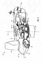
- Figure 3 is a partially cut-away perspective view of a portion of wind turbine 20.
- Wind turbine 20 described and shown herein is a wind turbine generator for generating electrical power from wind energy.
- wind turbine 20 described and illustrated herein includes a horizontal-axis configuration.
- wind turbine 20 may include, in addition or alternative to the horizontal-axis configuration, a vertical-axis configuration (not shown).
- Wind turbine 20 may be coupled to an electrical load (not shown in Figure 2 ), such as, but not limited to, a power grid, for receiving electrical power therefrom to drive operation of wind turbine 20 and/or its associated components and/or for supplying electrical power generated by wind turbine 20 thereto.
- an electrical load not shown in Figure 2
- a plurality of wind turbines 20 may be grouped together, sometimes referred to as a "wind farm.”
- Wind turbine 20 includes a body or nacelle 22 and a rotor (generally designated by 24) coupled to nacelle 22 for rotation with respect to nacelle 22 about an axis of rotation 26.
- nacelle 22 is mounted on a tower 28.
- nacelle 22 may be positioned adjacent the ground and/or a surface of water.
- the height of tower 28 may be any suitable height enabling wind turbine 20 to function as described herein.
- Rotor 24 includes a hub 30 and a plurality of blades 32 (sometimes referred to as "airfoils”) extending radially outwardly from hub 30 for converting wind energy into rotational energy.
- Blades 32 may each have any length that allows wind turbine 20 to function as described herein.
- one or more rotor blades 32 are about one-half meter long, while in some embodiments one or more rotor blades 32 are about fifty meters long.
- Other examples of blade 32 lengths include ten meters or less, about twenty meters, about thirty-seven meters, and about forty meters.
- Still other examples include rotor blades between about fifty and about one-hundred meters long, and rotor blades greater than one-hundred meters long.
- rotor 24 may have blades 32 of any shape, and may have blades 32 of any type and/or any configuration, whether such shape, type, and/or configuration is described and/or illustrated herein.
- One example of another type, shape, and/or configuration of blades 32 is a Darrieus wind turbine, sometimes referred to as an "eggbeater" turbine.
- Yet another example of another type, shape, and/or configuration of blades 32 is a Savonious wind turbine.
- wind turbine 20 may, in some embodiments, be a wind turbine wherein rotor 24 generally faces upwind to harness wind energy, and/or may be a wind turbine wherein rotor 24 generally faces downwind to harness energy.
- rotor 24 may not face exactly upwind and/or downwind, but may face generally at any angle (which may be variable) with respect to a direction of the wind to harness energy therefrom.
- wind turbine 20 includes an electrical generator 34 coupled to rotor 24 for generating electrical power from the rotational energy generated by rotor 24.
- Generator 34 may be any suitable type of electrical generator, such as, but not limited to, a wound rotor induction generator, a double-fed induction generator (DFIG, also known as dual-fed asynchronous generators), a permanent magnet (PM) synchronous generator, an electrically-excited synchronous generator, and a switched reluctance generator.
- Generator 34 includes a stator (not shown) and a rotor (not shown) with an air gap included therebetween.
- Rotor 24 includes a rotor shaft 36 coupled to rotor hub 30 for rotation therewith.
- Generator 34 is coupled to rotor shaft 36 such that rotation of rotor shaft 36 drives rotation of the generator rotor, and therefore operation of generator 34.
- the generator rotor has a generator shaft 38 coupled thereto and coupled to rotor shaft 36 such that rotation of rotor shaft 36 drives rotation of the generator rotor.
- the generator rotor is directly coupled to rotor shaft 36, sometimes referred to as a "direct-drive wind turbine.”
- generator shaft 38 is coupled to rotor shaft 36 through a gearbox 40, although in other embodiments generator shaft 38 is coupled directly to rotor shaft 36.
- the torque of rotor 24 drives the generator rotor to thereby generate variable frequency AC electrical power from rotation of rotor 24.
- Generator 34 has an air gap torque between the generator rotor and stator that opposes the torque of rotor 24.
- a power conversion assembly 42 is coupled to generator 34 for converting the variable frequency AC to a fixed frequency AC for delivery to an electrical load (not shown in Figure 3 ), such as, but not limited to an electrical grid (not shown in Figure 3 ), coupled to generator 34.
- Power conversion assembly 42 may include a single frequency converter or a plurality of frequency converters configured to convert electricity generated by generator 34 to electricity suitable for delivery over the power grid. Power conversion assembly 42 may also be referred to herein as a power converter.
- Power conversion assembly 42 may be located anywhere within or remote to wind turbine 20. For example, power conversion assembly 42 may be located within a base (not shown) of tower 28.
- wind turbine 20 includes at least one system controller 44 coupled to at least one component of wind turbine 20 for generally controlling operation of wind turbine 20 and/or controlling operation of the components thereof.
- system controller 44 may be configured to control operation of power conversion assembly 42, a disk brake 46, a yaw system 48, and/or a variable blade pitch system 50.
- Disk brake 46 brakes rotation of rotor 24 to, for example, slow rotation of rotor 24, brake rotor 24 against full wind torque, and/or reduce the generation of electrical power from electrical generator 34.
- variable blade pitch system 50 controls, including but not limited to changing, a pitch angle of blades 32 (shown in Figures 2-3 ) with respect to a wind direction.
- Pitch system 50 may be coupled to system controller 44 for control thereby.
- Pitch system 50 is coupled to hub 30 and blades 32 for changing the pitch angle of blades 32 by rotating blades 32 with respect to hub 30.
- the pitch actuators may include any suitable structure, configuration, arrangement, means, and/or components, whether described and/or shown herein, such as, but not limited to, electrical motors, hydraulic cylinders, springs, and/or servomechanisms.
- the pitch actuators may be driven by any suitable means, whether described and/or shown herein, such as, but not limited to, hydraulic fluid, electrical power, electrochemical power, and/or mechanical power, such as, but not limited to, spring force.
- FIG 4 is a block diagram of an exemplary embodiment of wind turbine 20.
- wind turbine 20 includes one or more system controller 44 coupled to at least one component of wind turbine 20 for generally controlling operation of wind turbine 20 and/or controlling operation of the components thereof, regardless of whether such components are described and/or shown herein.
- system controller 44 is coupled to pitch system 50 for generally controlling rotor 24.
- system controller 44 is mounted within nacelle 22 (shown in Figure 3 ), however, additionally or alternatively, one or more system controller 44 may be remote from nacelle 22 and/or other components of wind turbine 20.
- System controllers 44 may be used for overall system monitoring and control including, without limitation, pitch and speed regulation, high-speed shaft and yaw brake application, yaw and pump motor application, and/or fault monitoring.
- Alternative distributed or centralized control architectures may be used in some embodiments.
- wind turbine 20 includes a plurality of sensors, for example, sensors 54, 56, and 58.
- Sensors 54, 56, and 58 measure a variety of parameters including, without limitation, operating conditions and atmospheric conditions.
- Each sensor 54, 56, and 58 may be an individual sensor or may include a plurality of sensors.
- Sensors 54, 56, and 58 may be any suitable sensor having any suitable location within or remote to wind turbine 20 that allows wind turbine 20 to function as described herein.
- sensors 54, 56, and 58 are coupled to system controller 44 for transmitting measurements to system controller 44 for processing thereof.
- system controller 44 includes a bus 62 or other communications device to communicate information.
- processor(s) 64 are coupled to bus 62 to process information, including information from sensors 54, 56, 58 and/or other sensor(s).
- Processor(s) 64 may include at least one computer.
- the term computer is not limited to integrated circuits referred to in the art as a computer, but broadly refers to a processor, a microcontroller, a microcomputer, a programmable logic controller (PLC), an application specific integrated circuit, and other programmable circuits, and these terms are used interchangeably herein.
- System controller 44 may also include one or more random access memories (RAM) 66 and/or other storage device(s) 68.
- RAM(s) 66 and storage device(s) 68 are coupled to bus 62 to store and transfer information and instructions to be executed by processor(s) 64.
- RAM(s) 66 (and/or storage device(s) 68, if included) can also be used to store temporary variables or other intermediate information during execution of instructions by processor(s) 64.
- System controller 44 may also include one or more read only memories (ROM) 70 and/or other static storage devices coupled to bus 62 to store and provide static (i.e., non-changing) information and instructions to processor(s) 64.
- ROM read only memories
- Processor(s) 64 process information transmitted from a plurality of electrical and electronic devices that may include, without limitation, speed and power transducers. Instructions that are executed include, without limitation, resident conversion and/or comparator algorithms. The execution of sequences of instructions is not limited to any specific combination of hardware circuitry and software instructions.
- System controller 44 may also include, or may be coupled to, input/output device(s) 72.
- Input/output device(s) 72 may include any device known in the art to provide input data to system controller 44 and/or to provide outputs, such as, but not limited to, yaw control and/or pitch control outputs.
- Instructions may be provided to RAM 66 from storage device 68 including, for example, a magnetic disk, a read-only memory (ROM) integrated circuit, CD-ROM, and/or DVD, via a remote connection that is either wired or wireless providing access to one or more electronically-accessible media.
- ROM read-only memory
- DVD digital versatile discs
- hard-wired circuitry can be used in place of or in combination with software instructions.
- input/output device(s) 72 may include, without limitation, computer peripherals associated with an operator interface such as a mouse and a keyboard (neither shown in Figure 4 ). Alternatively, other computer peripherals may also be used that may include, for example, a scanner (not shown in Figure 4 ). Furthermore, in the exemplary embodiment, additional output channels may include, for example, an operator interface monitor (not shown in Figure 4 ).
- System controller 44 may also include a sensor interface 74 that allows system controller 44 to communicate with sensors 54, 56, 58 and/or other sensor(s). Sensor interface 74 may include one or more analog-to-digital converters that convert analog signals into digital signals that can be used by processor(s) 64.
- wind turbine 20 includes a phase locked loop (PLL) regulator 80.
- PLL regulator 80 is coupled to sensor 56.
- sensor 56 is a voltage transducer configured to measure a terminal grid voltage output by power conversion assembly 42.
- PLL regulator 80 is configured to receive a plurality of voltage measurement signals from a plurality of voltage transducers.
- each of three voltage transducers is electrically coupled to each one of three phases of a grid bus.
- PLL regulator 80 may be configured to receive any number of voltage measurement signals from any number of voltage transducers that allow PLL regulator 80 to function as described herein.
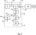
- FIG. 5 is a block diagram of an exemplary power generation and delivery system 150.
- Power generation and delivery system 150 may be used with, or included within, wind turbine 20 (shown in Figures 2 and 3 ).
- System 150 includes an energy source, for example, generator 34. Although described herein as wind turbine generator 34, the energy source may include any type of electrical generator that allows system 150 to function as described herein, e.g. a solar power generation system.
- System 150 also includes a power converter, such as, power conversion assembly 42.
- Power conversion assembly 42 receives electrical power (Pv) 132 generated by generator 34 and converts electrical power 132 to an electrical power (Pt) 134 (referred to herein as terminal power 134) suitable for transmission over an electric power transmission and distribution grid 136 (referred to herein as utility grid 136).
- a terminal voltage (Vt) 138 is defined at a node between power conversion assembly 42 and utility grid 136.
- a bulk power system 140 is coupled to utility grid 136. Bulk power system 140 includes a plurality of loads
- system 150 includes a grid-dependent power limiter system 152.
- a controller for example, but not limited to, system controller 44 (shown in Figure 4 ), is programmed to perform the functions of grid-dependent power limiter system 152.
- the functions of grid-dependent power limiter system 152 may be performed by any circuitry configured to allow system 150 to function as described herein.
- Power limiter system 152 is configured to identify the occurrence of a grid contingency event, and provide power conversion assembly 42 with control signals that facilitate providing a stable recovery from the grid event. Generally, upon detection of a grid contingency event, power limiter system 152 provides signals to reduce the power output of power conversion assembly 42.
- power limiter system 152 During recovery from the grid contingency event, power limiter system 152 provides signals to increase the active power output of power conversion assembly 42. In some embodiments, power limiter system 152 provides a signal, or signals, to increase the active power output of power conversion assembly 42 gradually until the output power of power conversion assembly 42 is returned to its pre-fault level.
- system 150 also includes a stabilizer system 182 (shown in Figure 6 ) configured to output a command signal that is provided to converter interface controller 156 and used to control operation of power converter 42.
- a controller for example, but not limited to, system controller 44 (shown in Figure 4 ), is programmed to perform the functions of stabilizer system 182.
- the functions of stabilizer system 182 may be performed by any circuitry configured to allow system 150 to function as described herein.
- Oscillations within an output of power converter 42 are reduced when power converter 42 is operated in accordance with control signals from converter interface controller 156 that are based at least partially on the command signal, for example, a reactive current command signal 192 and/or a real current command signal 166.
- stabilizer system 182 includes a regulator 184 and a regulator stabilizer 186.
- regulator 184 is a voltage regulator configured to generate a reactive power command, for example, reactive current command signal 192.
- Regulator stabilizer 186 is configured to generate a regulator stabilization signal 188 that stabilizes regulator 184 as system 150 recovers from a grid contingency event.
- regulator stabilizer 186 may generate a voltage regulator stabilization signal and/or a power regulator stabilization signal.
- power conversion assembly 42 responds according to the signals provided by stabilizer system 182 and reduces system oscillations that may occur during recovery from the grid event.
- a grid event may leave utility grid 136 in a degraded mode where the grid impedance is high.
- An example of a grid event includes a short-circuit fault on one of the transmission lines within utility grid 136. Electrical transmission protection actions remove the faulted portion of utility grid 136 to permit operation of the remaining unfaulted portion of utility grid 136.
- a transmission path remains that is degraded in its ability to transmit power from system 150 to bulk power system 140.
- Such grid events cause a brief period of low voltage on utility grid 136 prior to clearing the faulted portion of the utility grid 136.
- terminal voltage 138 will be significantly degraded at the time of the grid event.
- the high grid impedance after the fault clearing can result in an oscillatory response of the regulators within the generator (e.g., power regulator 204 and/or voltage regulator 184). These oscillations are typically in a frequency range of approximately 10 hertz (Hz) to 30 Hz, and in some instances, can become unstable if not properly accounted for by system 150.
- Hz hertz
- power conversion assembly 42 is configured to receive control signals 154 from a converter interface controller 156.
- Control signals 154 are based on sensed operating conditions or operating characteristics of wind turbine 20 as described herein and used to control the operation of power conversion assembly 42. Examples of measured operating conditions may include, but are not limited to, a terminal grid voltage, a PLL error, a stator bus voltage, a rotor bus voltage, and/or a current.
- sensor 56 shown in Figure 4
- PLL regulator 80 (shown in Figure 4 ) may generate a PLL error signal 190 and transmit signal 190 to stabilizer system 182 and power limiter system 152.
- voltage regulator stabilizer 186 generates, based at least partially on PLL error signal 190, voltage regulator stabilization signal 188 and transmits voltage regulator stabilization signal 188 to voltage regulator 184.
- Voltage regulator 184 generates reactive current command signal 192, based at least partially on voltage regulator stabilization signal 188 and transmits reactive current command signal 192 to converter interface controller 156.
- power limiter system 152 also receives terminal voltage feedback signal 160 and generates a power command signal, for example, real current command signal 166 based at least partially on PLL error signal 190 and terminal voltage feedback signal 160.
- PLL error signal 190 may oscillate as system 150 gradually increases an active power output of power conversion assembly 42.
- oscillations within PLL error signal 190 are indicative of system oscillations.
- Voltage regulator stabilizer 186 applies a transfer function to the oscillating PLL error signal 190, which outputs voltage regulator stabilization signal 188.
- This feedback loop is configured to reduce system oscillations.
- system oscillations occurring after a grid contingency event are identified by oscillations in PLL error signal 190, PLL error signal 190 is provided to voltage regulator stabilizer 186, voltage regulator stabilizer 186 generates voltage regulator stabilization signal 188, and voltage regulator stabilization signal 188 is provided to voltage regulator 184.
- Voltage regulator stabilization signal 188 causes reactive current command signal 192 to oscillate in a manner that reduces and/or cancels system oscillations.
- Voltage regulator 184 transmits reactive current command signal 192 to converter interface controller 156.
- converter interface controller 156 is included within system controller 44. Other operating condition feedback from other sensors also may be used by controller 44 and/or converter interface controller 156 to control power conversion assembly 42.
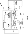
- FIG. 6 is a block diagram of an exemplary converter control system 200 configured to generate control signals provided to a power converter, for example, power conversion assembly 42 (shown in Figure 5 ), for control of power conversion assembly 42.
- converter control system 200 includes power limiter system 152, stabilizer system 182, and converter interface controller 156.
- power limiter system 152 includes a power limiter 202 and a power regulator 204 and outputs a power command signal, for example, real current command signal 166.
- power limiter 180 receives at least one measured operating condition of system 150.
- the at least one measured operating condition may include, but is not limited to, a PLL error signal 190 from PLL regulator 80 and terminal grid voltage feedback signal 160 from sensor 54.
- Power limiter 180 also receives a stored reference power control signal 194 from, for example, system controller 44 (shown in Figure 3 ). In some embodiments, power limiter 180 receives terminal grid voltage feedback signal 160 and stored reference power control signal 194. In other embodiments, power limiter 180 receives PLL error signal 190 and stored reference power control signal 194. In other embodiments, power limiter 180 receives both PLL error signal 190 and terminal grid voltage feedback signal 160, as well as stored reference power control signal 194. In the exemplary embodiment, power limiter 180 generates a power command signal 206 and transmits power command signal 206 to power regulator 204. Power regulator 204 generates real current command signal 166 and transmits real current command signal 166 to converter interface controller 156. Converter interface controller 156 may also be referred to herein as a converter firing control. As described above, PLL regulator 80 may be included within system controller 44, or may be coupled to, but separate from, system controller 44.
- PLL regulator 80 receives terminal voltage feedback signal 160.
- PLL regulator 80 may receive terminal voltage feedback signal 160 (shown in Figure 3 as Vt) provided by sensor 54 (shown in Figure 3 ).
- PLL regulator 80 generates PLL error signal 190 and a PLL phase angle signal 208.
- PLL phase angle signal 208 is transmitted to converter interface controller 156 for control of power conversion assembly 42 and for subsequent control of electrical currents injected onto utility grid 136 (shown in Figure 4 ).
- voltage regulator stabilizer 186 also receives PLL error signal 190. Furthermore, in the exemplary embodiment, voltage regulator stabilizer 186 applies a predefined transfer function to PLL error signal 190 to generate voltage regulator stabilization signal 188. Voltage regulator stabilization signal 188 is applied to voltage regulator 184, which combines signal 188 with voltage feedback signal 160 to generate reactive current command signal 192. Oscillations within PLL error signal 190 provide an indication of system oscillations that may occur after a grid contingency event. More specifically, oscillations within PLL error signal 190 correspond to system oscillations, for example, oscillations within terminal voltage 138 (shown in Figure 5 ) and/or oscillations within output power 134 (shown in Figure 5 ). Determining reactive current command signal 192 based partially on PLL error signal 190 facilitates reducing the system oscillations.
- An example of the transfer function applied by voltage regulator stabilizer 186 isolates a frequency range within PLL error signal 190 that includes an indication of regulator oscillations (e.g., a band pass filter between 10 Hz and 30 Hz), and applies a gain selected to cause the regulator oscillations to be positively damped.
- the transfer function may be determined based on, for example, calculations, simulations, and/or testing where voltage regulator stabilizer 186 applies various voltage regulator stabilization signals 188 to voltage regulator 184.
- the transfer function may include linear components, for example, band pass filtering and gain, and may also include any nonlinear components, for example, but not limited to, limiters and dead bands, that allow system 150, in conjunction with electrical grid 136, to function as described herein. More specifically, voltage regulator stabilizer 186 may apply linear and/or nonlinear transfer functions to PLL error signal 190 to generate a voltage regulator stabilization signal 188 that dampens system oscillations.
- Voltage regulator 184 receives voltage regulator stabilization signal 188 and generates reactive current command signal 192.
- Reactive current command signal 192 is provided to converter interface controller 156, which controls operation of power conversion assembly 42 in accordance with reactive current command signal 192.
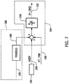
- FIG 7 is a block diagram of an exemplary voltage regulator, for example, voltage regulator 184 (shown in Figure 6 ) and an exemplary voltage regulator stabilizer, for example voltage regulator stabilizer 186 (shown in Figure 6 ).
- voltage regulator stabilizer 186 receives PLL error signal 190 and generates voltage regulator stabilization signal 188.
- Voltage regulator 184 generates reactive current command signal 192 based on voltage regulator stabilization signal 188 and voltage feedback signal 160 and sends reactive current command signal 192 to converter interface controller 156.
- Reactive current command signal 192 instructs converter interface controller 156 to inject current onto utility grid 136 that includes a reactive component configured to dampen power output oscillations. Dampening power output oscillations increases the stability of grid 136 and power generation and delivery system 150.
- voltage regulator 184 receives voltage stabilizer signal 188 from voltage regulator stabilizer 186, receives terminal voltage feedback signal 160, and receives a reference voltage command signal (VREF) 240 from at least one volt-ampere reactive (VAR) regulator 242.
- VREF 240 is also referred to herein as a reference voltage.
- power limiter system 152 Upon detection of a grid contingency event, power limiter system 152 transmits real current command signal 166 (shown in Figure 6 ) to converter interface controller 156 to reduce the output power of power conversion assembly 42. After the grid contingency event is completed, power limiter system 152 generates signals, for example real current command signal 166, that command a gradual increase in the power output of power conversion assembly 42.
- voltage regulator 184 During the grid contingency event, e.g., terminal voltage 138 indicates occurrence of a grid contingency event, voltage regulator 184 generates a reactive current command signal 192 that increases the reactive current output by power conversion assembly 42 to support terminal grid voltage 138 until the grid contingency event is resolved. At the resolution of the grid contingency event, reactive current command signal 192 returns to a lower level, causing reactive current output by power conversion assembly 42 to decrease to approximately the level of reactive current output by power conversion assembly 42 prior to the grid contingency event. As the output power of power conversion assembly 42 increases during recovery from the grid contingency event, additional reactive current may be needed to maintain terminal voltage 138 and avoid voltage collapse of utility grid 136.
- voltage regulator stabilizer 186 To facilitate reducing oscillations in the output power of conversion assembly 42, voltage regulator stabilizer 186 generates voltage regulator stabilization signal 188 and transmits voltage regulator stabilization signal 188 to voltage regulator 184. Voltage regulator stabilization signal 188 is added to reference voltage command signal 240. Hence, voltage regulator 184 generates a reactive current command signal 192 that includes a reactive current component configured to cancel oscillations in the power output by power conversion assembly 42. Voltage regulator 184 sums voltage regulator stabilization signal 188 and reference voltage command signal 240 and subtracts terminal voltage feedback signal 160 to produce an error signal. A control block 246 receives the error signal and generates reactive current command signal 192.
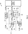
- FIG 8 is a block diagram of an alternative embodiment of converter control system 200 (shown in Figure 6 ) and identified herein as converter control system 220.
- Converter control system 220 is configured to generate control signals provided to a power converter, for example, power conversion assembly 42 (shown in Figure 5 ), for control of power conversion assembly 42.
- stabilizer system 182 includes power regulator 204 that is configured to generate a real power command, for example, real current command signal 166.
- regulator stabilizer 186 is a power regulator stabilizer configured to generate stabilization signal 188, which is, more specifically, a power stabilization signal.
- Power stabilization signal 188 is provided to power regulator 204, which generates control signals based at least partially on signal 188.
- the control signals, for example, real current command signal 166 are provided to converter interface controller 156.
- converter control system 220 includes power limiter system 152, stabilizer system 182, and converter interface controller 156.
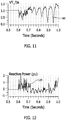
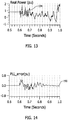
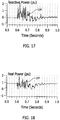
- Figures 9-18 are graphical views illustrating operation of a power generation and delivery system after a grid contingency event. More specifically, Figures 9-13 illustrate operation of a power generation and delivery system that does not include a regulator stabilizer, for example, regulator stabilizer 186 (shown in Figure 6 ). In contrast, Figures 14-18 illustrate operation of a power generation and delivery system, for example, power generation and delivery system 150 (shown in Figure 5 ), that includes regulator stabilizer 186. The exemplary measurements illustrated in Figures 9-18 were obtained through experimentation and/or calculation and are included to illustrate the effect of operation of regulator stabilizer 186 on power generation and delivery system 150.
- Figures 9 and 14 are graphical views of PLL error signal 190 versus time. As described above, after a grid contingency event, system oscillations arising from operation of voltage regulator 184 (shown in Figure 6 ) are measured and apparent in PLL error signal 190 (see Figure 9 ). Figure 14 illustrates the reduction in system oscillations, as shown by the reduction in PLL error signal 190 oscillations.
- Figures 10 and 15 are graphical views of a sum 250 of reference voltage command signal 240 and voltage regulator stabilization signal 188 (both shown in Figure 7 ) versus time. As illustrated in Figure 10 , without voltage regulator stabilizer 186, no voltage regulator stabilization signal 188 is provided to voltage regulator 184. Therefore, sum 250 of reference voltage command signal 240 and voltage regulator stabilization signal 188 equals reference voltage command signal 240, which in the illustrated example, is a constant over time.
- reference voltage command signal 240 As shown in Figure 15 , sum 250 of reference voltage command signal 240 and voltage regulator stabilization signal 188 varies over time. Reference voltage command signal 240 remains a constant, however, voltage regulator stabilization signal 188 varies over time.
- Figures 11 and 16 are graphical views of terminal voltage feedback signal 160 (shown in Figure 7 ) versus time.
- the oscillation of terminal voltage feedback signal 160 is an example of a system oscillation that occurs, for example, while system 150 is recovering from a grid contingency event.
- Figure 11 illustrates a system oscillation (e.g., oscillations of terminal voltage feedback signal 160) increasing over time.
- Figure 16 illustrates the reduction in system oscillations (e.g., reduction in terminal voltage feedback signal 160 oscillations), caused by operation of voltage regulator stabilizer 186. More specifically, Figure 16 illustrates how application of sum 250 (shown in Figure 15 ) to operation of voltage regulator 184 dampens oscillations of terminal voltage feedback signal 160.
- Figures 12 and 13 are graphical views of electrical power 134 (shown in Figure 5 ) versus time in a power generation and delivery system that does not include voltage regulator stabilizer 186. More specifically, Figure 12 illustrates a reactive power component of electrical power 134 and Figure 13 illustrates a real power component of electrical power 134.
- the oscillations of electrical power 134 illustrated in Figures 12 and 13 are another example of system oscillations that may occur while system 150 is recovering from a grid contingency event.
- Figures 17 and 18 are graphical views of electrical power 134 (shown in Figure 5 ) versus time in a power generation system that includes a voltage regulator stabilizer, for example, power generation system 150 that includes voltage regulator stabilizer 186.
- Figures 17 and 18 illustrate the reduction in system oscillations, more specifically, the reduction in the oscillations of electrical power 134, caused by operation of voltage regulator stabilizer 186.
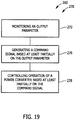
- FIG 19 is a flow chart 260 of an exemplary method 270 for controlling a power generation and delivery system, for example, power generation and delivery system 150 (shown in Figure 5 ).
- power generation and delivery system 150 includes an electrical generator, for example, electrical generator 34 (shown in Figure 5 ), a power converter, for example power conversion assembly 42 (shown in Figure 5 ), and a system controller, for example, system controller 44 (shown in Figure 4 ).
- method 270 includes monitoring 272 an output parameter of power generation and delivery system 150 that is indicative of system oscillations.
- a PLL regulator for example, PLL regulator 80 (shown in Figure 4 ) may monitor 272 a PLL error, and generate a PLL error signal, for example, PLL error signal 190.
- the output parameter may also include, but is not limited to, a voltage feedback signal, for example, voltage feedback signal 160 (shown in Figure 5 ).
- oscillations within PLL error signal 190 are indicative of system oscillations.
- method 270 also includes generating 276 a command signal, for example, reactive current command signal 192 (shown in Figure 5 ) and/or real current command signal 166 (shown in Figure 5 ), based at least partially on the output parameter.
- system controller 44 may generate 276 the command signal by applying a transfer function to PLL error signal 190 to generate a voltage regulator stabilization signal, for example, voltage regulator stabilization signal 188 (shown in Figure 6 ).
- a voltage regulator for example, voltage regulator 184 (shown in Figure 6 ) is configured to generate command signal 192 based at least partially on voltage regulator stabilization signal 188.
- system controller 44 may generate 276 the command signal by applying a transfer function to PLL error signal 190 to generate a power regulator stabilization signal, for example, power regulator stabilization signal 188 (shown in Figure 8 ).
- a power regulator for example, power regulator 204 (shown in Figure 8 ) is configured to generate command signal 166 based at least partially on power regulator stabilization signal 188.
- generating 276 command signal 192 may include summing voltage regulator stabilization signal 188, a reference voltage command signal, for example, reference voltage command signal 240 (shown in Figure 7 ), and an inverse of terminal voltage feedback signal 160 (shown in Figure 7 ).
- applying the transfer function may include applying a predefined transfer function to PLL error signal 190 that isolates a frequency range within PLL error signal 190 that includes an indication of system oscillations. Applying the transfer function may also include applying a predefined gain to PLL error signal 190 to positively dampen system oscillations.
- method 270 also includes controlling 278 operation of power converter 42 based at least partially on reactive current command signal 192 and/or the real current command signal 166 to reduce system oscillations.
- the above-described embodiments can facilitate efficient and cost-effective operation of a wind turbine.
- the wind turbine includes a voltage regulator stabilizer system that generates a voltage regulator stabilization signal based at least partially on a measured PLL error.
- the voltage regulator stabilization signal is provided to a voltage regulator that determines a reactive current command based at least partially on the voltage regulator stabilization signal. Controlling the reactive current output as a function of the PLL error facilitates reducing system oscillations that may occur during recovery from a grid contingency event.
- the method and systems described herein facilitate increasing the stability of the voltage regulator, and furthermore, the stability voltage and/or power output by the wind turbine following a grid contingency event.
- Exemplary embodiments of a wind turbine, voltage regulator stabilizer system, and methods for operating a wind turbine in response to an occurrence of a grid contingency event are described above in detail.
- the methods, wind turbine, and voltage regulator stabilizer system are not limited to the specific embodiments described herein, but rather, components of the wind turbine, components of the voltage regulator stabilizer system, and/or steps of the methods may be utilized independently and separately from other components and/or steps described herein.
- the voltage regulator stabilizer system and methods may also be used in combination with other wind turbine power systems and methods, and are not limited to practice with only the power system as described herein. Rather, the exemplary embodiment can be implemented and utilized in connection with many other wind turbine or power system applications.
Description
- The subject matter described herein relates generally to controlling operation of power generation and delivery systems, and more specifically, to stabilizing a power converter after an electrical grid contingency event.
- Wind turbine generators utilize wind energy to produce electrical power. Wind turbine generators typically include a rotor having multiple blades that transform wind energy into rotational motion of a drive shaft, which in turn is utilized to drive an electrical generator to produce electrical power. Each of the multiple blades may be pitched to increase or decrease the rotational speed of the rotor. A power output of a wind turbine generator increases with wind speed until the wind speed reaches a rated wind speed for the turbine. At and above the rated wind speed, the wind turbine generator operates at a rated power.
- Variable speed operation of the wind turbine generator facilitates enhanced capture of energy by the wind turbine generator when compared to a constant speed operation of the wind turbine generator. However, variable speed operation of the wind turbine generator produces electricity having varying voltage and/or frequency. More specifically, the frequency of the electricity generated by the variable speed wind turbine generator is proportional to the speed of rotation of the rotor. A power converter may be coupled between the electric generator and an electrical grid. The power converter outputs electricity having a fixed voltage and frequency for delivery on the electrical grid. See, for example,
US 2012/010759 . - Power generated by an electric utility, using renewable sources of energy or fossil fuel based sources of energy, is typically delivered to a customer over an electrical grid. Electricity applied to the electrical grid is required to meet grid connectivity expectations. These requirements address safety issues as well as power quality concerns. For example, the grid connectivity expectations include operating the power generation system during a transient event, also referred to herein as a grid fault event and/or a grid contingency event. This capability may be referred to as low voltage ride through (LVRT) or zero voltage ride through (ZVRT). An LVRT/ZVRT event is a condition where the alternating current (AC) utility voltage is low on either one phase of the electrical grid or multiple phases of the electrical grid. During an LVRT/ZVRT event, the capacity of the electrical grid to accept power from the power generation system is low. Following switching actions in the external grid, the impedance of the grid may increase substantially leading to a condition referred to herein as a "weak grid".
- Operation of the power converter is controlled to facilitate LVRT/ZVRT. Once the LVRT/ZVRT event dissipates, the power converter is controlled to facilitate recovery from the event and return the power generation system to steady-state operation. During the recovery, system oscillations may cause instability, for example, instability in a power output by the power converter.
- Various aspects and embodiments of the present invention will now be described in connection with the accompanying drawings, in which:
-
Figure 1 is a block diagram of an exemplary power generation system. -
Figure 2 is a perspective view of a portion of an exemplary wind turbine that may be used in the power generation system shown inFigure 1 . -
Figure 3 is a partially cut-away view of a portion of the wind turbine shown inFigure 2 . -
Figure 4 is a block diagram of the wind turbine shown inFigure 2 . -
Figure 5 is a block diagram of an exemplary power generation and delivery system that may include the wind turbine shown inFigure 2 . -
Figure 6 is a block diagram of an exemplary converter control system that may be included within the power generation and delivery system shown inFigure 5 . -
Figure 7 is a block diagram of an exemplary stabilizer system that may be included within the converter control system shown inFigure 6 . -
Figure 8 is a block diagram of an alternative converter control system that may be included within the power generation and delivery system shown inFigure 5 . -
Figures 9-18 are graphical views illustrating operation of a power generation and delivery system after a grid contingency event. -
Figure 19 is a flow chart of an exemplary method for controlling the power generation and delivery system shown inFigure 5 . - As used herein, the term "blade" is intended to be representative of any device that provides reactive force when in motion relative to a surrounding fluid. As used herein, the term "wind turbine" is intended to be representative of any device that generates rotational energy from wind energy, and more specifically, converts kinetic energy of wind into mechanical energy. As used herein, the term "wind turbine generator" is intended to be representative of any wind turbine that generates electrical power from rotational energy generated from wind energy, and more specifically, converts mechanical energy converted from kinetic energy of wind to electrical power.
- Various technical effects of the methods, systems, and computer-readable media described as embodiments herein may include at least one of: (a) monitoring an output parameter of the power generation and delivery system, wherein oscillations within the output parameter correspond to system oscillations; (b) generating a command signal based at least partially on the output parameter; and, (c) controlling operation of the power converter based at least partially on the command signal to reduce system oscillations.
- Various embodiments of the methods, systems, and computer readable media described herein may facilitate reducing system oscillations that may occur during recovery from a grid contingency event. As described herein, a voltage regulator stabilizer generates a voltage regulator stabilization signal based at least partially on a measured PLL error. The voltage regulator stabilization signal is provided to a voltage regulator that determines a reactive current command based at least partially on the voltage regulator stabilization signal. Furthermore, a power regulator stabilizer may generate a power regulator stabilization signal based at least partially on the measured PLL error. The power regulator stabilization signal is provided to a power regulator that determines a real current command based at least partially on the power regulator stabilization signal. Controlling the reactive current output and/or the real current output of the power converter as a function of the PLL error facilitates reducing system oscillations that may occur during recovery from a grid contingency event. Furthermore, reducing system oscillations stabilizes the power generation system and utility grid. Although generally described herein with respect to a wind turbine, the methods and systems described herein are applicable to any type of electric generation system including, for example, solar power generation systems, fuel cells, geothermal generators, hydropower generators, and/or other devices that generate power from renewable and/or non-renewable energy sources.
-
Figure 1 is a block diagram of an exemplarypower generation system 10 that includes apower generator 12.Power generator 12 includes one or morepower generation units 14.Power generation units 14 may include, for example, wind turbines, solar cells, fuel cells, geothermal generators, hydropower generators, and/or other devices that generate power from renewable and/or non-renewable energy sources. Although threepower generation units 14 are shown in the exemplary embodiment, in other embodiments,power generator 12 may include any suitable number ofpower generation units 14, including only onepower generation unit 14. - In the exemplary embodiment,
power generator 12 is coupled to apower converter 16, or apower converter system 16, that converts a substantially direct current (DC) power output frompower generator 12 to alternating current (AC) power. The AC power is transmitted to anelectrical distribution network 18, or "grid."Power converter 16, in the exemplary embodiment, adjusts an amplitude of the voltage and/or current of the converted AC power to an amplitude suitable forelectrical distribution network 18, and provides AC power at a frequency and a phase that are substantially equal to the frequency and phase ofelectrical distribution network 18. Moreover, in the exemplary embodiment,power converter 16 provides three phase AC power toelectrical distribution network 18. Alternatively,power converter 16 provides single phase AC power or any other number of phases of AC power toelectrical distribution network 18. Furthermore, in some embodiments,power generation system 10 may include more than onepower converter 16. For example, in some embodiments, each power generation unit may be coupled to aseparate power converter 16. - In an exemplary embodiment,
power generation units 14 include solar panels coupled to form one or more solar arrays to facilitate operatingpower generation system 10 at a desired power output. Eachpower generation unit 14 may be an individual solar panel or an array of solar panels. In one embodiment,power generation system 10 includes a plurality of solar panels and/or solar arrays coupled together in a series-parallel configuration to facilitate generating a desired current and/or voltage output frompower generation system 10. Solar panels include, in one embodiment, one or more of a photovoltaic panel, a solar thermal collector, or any other device that converts solar energy to electrical energy. In the exemplary embodiment, each solar panel is a photovoltaic panel that generates a substantially direct current power as a result of solar energy striking solar panels. In the exemplary embodiment, the solar array is coupled topower converter 16, orpower converter system 16, that converts the DC power to alternating current power that is transmitted toelectrical distribution network 18. - In other embodiments,
power generation units 14 include one or more wind turbines coupled to facilitate operatingpower generation system 10 at a desired power output. Each wind turbine generates substantially direct current power. The wind turbines are coupled topower converter 16, orpower converter system 16, that converts the DC power to AC power that is transmitted to anelectrical distribution network 18, or "grid." Methods and systems will be further described herein with reference to such a wind turbine based power generation system. However, the methods and systems described herein are applicable to any type of electric generation system including, for example, fuel cells, geothermal generators, hydropower generators, and/or other devices that generate power from renewable and/or non-renewable energy sources. -
Figure 2 is a perspective view of anexemplary wind turbine 20 that may be used inpower generation system 10.Figure 3 is a partially cut-away perspective view of a portion ofwind turbine 20.Wind turbine 20 described and shown herein is a wind turbine generator for generating electrical power from wind energy. Moreover,wind turbine 20 described and illustrated herein includes a horizontal-axis configuration. However, in some embodiments,wind turbine 20 may include, in addition or alternative to the horizontal-axis configuration, a vertical-axis configuration (not shown).Wind turbine 20 may be coupled to an electrical load (not shown inFigure 2 ), such as, but not limited to, a power grid, for receiving electrical power therefrom to drive operation ofwind turbine 20 and/or its associated components and/or for supplying electrical power generated bywind turbine 20 thereto. Although only onewind turbine 20 is shown inFigures 2 and3 , in some embodiments, a plurality ofwind turbines 20 may be grouped together, sometimes referred to as a "wind farm." -
Wind turbine 20 includes a body ornacelle 22 and a rotor (generally designated by 24) coupled tonacelle 22 for rotation with respect tonacelle 22 about an axis ofrotation 26. In the exemplary embodiment,nacelle 22 is mounted on atower 28. However, in some embodiments, in addition or alternative to tower-mountednacelle 22,nacelle 22 may be positioned adjacent the ground and/or a surface of water. The height oftower 28 may be any suitable height enablingwind turbine 20 to function as described herein.Rotor 24 includes ahub 30 and a plurality of blades 32 (sometimes referred to as "airfoils") extending radially outwardly fromhub 30 for converting wind energy into rotational energy. Althoughrotor 24 is described and illustrated herein as having threeblades 32,rotor 24 may have any number ofblades 32.Blades 32 may each have any length that allowswind turbine 20 to function as described herein. For example, in some embodiments, one ormore rotor blades 32 are about one-half meter long, while in some embodiments one ormore rotor blades 32 are about fifty meters long. Other examples ofblade 32 lengths include ten meters or less, about twenty meters, about thirty-seven meters, and about forty meters. Still other examples include rotor blades between about fifty and about one-hundred meters long, and rotor blades greater than one-hundred meters long. - Despite how
rotor blades 32 are illustrated inFigure 2 ,rotor 24 may haveblades 32 of any shape, and may haveblades 32 of any type and/or any configuration, whether such shape, type, and/or configuration is described and/or illustrated herein. One example of another type, shape, and/or configuration ofblades 32 is a Darrieus wind turbine, sometimes referred to as an "eggbeater" turbine. Yet another example of another type, shape, and/or configuration ofblades 32 is a Savonious wind turbine. Moreover,wind turbine 20 may, in some embodiments, be a wind turbine whereinrotor 24 generally faces upwind to harness wind energy, and/or may be a wind turbine whereinrotor 24 generally faces downwind to harness energy. Of course, in any of the embodiments,rotor 24 may not face exactly upwind and/or downwind, but may face generally at any angle (which may be variable) with respect to a direction of the wind to harness energy therefrom. - Referring now to
Figure 3 ,wind turbine 20 includes anelectrical generator 34 coupled torotor 24 for generating electrical power from the rotational energy generated byrotor 24.Generator 34 may be any suitable type of electrical generator, such as, but not limited to, a wound rotor induction generator, a double-fed induction generator (DFIG, also known as dual-fed asynchronous generators), a permanent magnet (PM) synchronous generator, an electrically-excited synchronous generator, and a switched reluctance generator.Generator 34 includes a stator (not shown) and a rotor (not shown) with an air gap included therebetween.Rotor 24 includes arotor shaft 36 coupled torotor hub 30 for rotation therewith.Generator 34 is coupled torotor shaft 36 such that rotation ofrotor shaft 36 drives rotation of the generator rotor, and therefore operation ofgenerator 34. In the exemplary embodiment, the generator rotor has agenerator shaft 38 coupled thereto and coupled torotor shaft 36 such that rotation ofrotor shaft 36 drives rotation of the generator rotor. In other embodiments, the generator rotor is directly coupled torotor shaft 36, sometimes referred to as a "direct-drive wind turbine." In the exemplary embodiment,generator shaft 38 is coupled torotor shaft 36 through agearbox 40, although in otherembodiments generator shaft 38 is coupled directly torotor shaft 36. - The torque of
rotor 24 drives the generator rotor to thereby generate variable frequency AC electrical power from rotation ofrotor 24.Generator 34 has an air gap torque between the generator rotor and stator that opposes the torque ofrotor 24. Apower conversion assembly 42 is coupled togenerator 34 for converting the variable frequency AC to a fixed frequency AC for delivery to an electrical load (not shown inFigure 3 ), such as, but not limited to an electrical grid (not shown inFigure 3 ), coupled togenerator 34.Power conversion assembly 42 may include a single frequency converter or a plurality of frequency converters configured to convert electricity generated bygenerator 34 to electricity suitable for delivery over the power grid.Power conversion assembly 42 may also be referred to herein as a power converter.Power conversion assembly 42 may be located anywhere within or remote towind turbine 20. For example,power conversion assembly 42 may be located within a base (not shown) oftower 28. - In the exemplary embodiment,
wind turbine 20 includes at least onesystem controller 44 coupled to at least one component ofwind turbine 20 for generally controlling operation ofwind turbine 20 and/or controlling operation of the components thereof. For example,system controller 44 may be configured to control operation ofpower conversion assembly 42, adisk brake 46, ayaw system 48, and/or a variableblade pitch system 50.Disk brake 46 brakes rotation ofrotor 24 to, for example, slow rotation ofrotor 24,brake rotor 24 against full wind torque, and/or reduce the generation of electrical power fromelectrical generator 34.Yaw system 48 for rotatingnacelle 22 about an axis ofrotation 52 for changing a yaw ofrotor 24, and more specifically for changing a direction faced byrotor 24 to, for example, adjust an angle between the direction faced byrotor 24 and a direction of wind. - Furthermore, variable
blade pitch system 50 controls, including but not limited to changing, a pitch angle of blades 32 (shown inFigures 2-3 ) with respect to a wind direction.Pitch system 50 may be coupled tosystem controller 44 for control thereby.Pitch system 50 is coupled tohub 30 andblades 32 for changing the pitch angle ofblades 32 by rotatingblades 32 with respect tohub 30. The pitch actuators may include any suitable structure, configuration, arrangement, means, and/or components, whether described and/or shown herein, such as, but not limited to, electrical motors, hydraulic cylinders, springs, and/or servomechanisms. Moreover, the pitch actuators may be driven by any suitable means, whether described and/or shown herein, such as, but not limited to, hydraulic fluid, electrical power, electrochemical power, and/or mechanical power, such as, but not limited to, spring force. -
Figure 4 is a block diagram of an exemplary embodiment ofwind turbine 20. In the exemplary embodiment,wind turbine 20 includes one ormore system controller 44 coupled to at least one component ofwind turbine 20 for generally controlling operation ofwind turbine 20 and/or controlling operation of the components thereof, regardless of whether such components are described and/or shown herein. For example, in the exemplaryembodiment system controller 44 is coupled to pitchsystem 50 for generally controllingrotor 24. In the exemplary embodiment,system controller 44 is mounted within nacelle 22 (shown inFigure 3 ), however, additionally or alternatively, one ormore system controller 44 may be remote fromnacelle 22 and/or other components ofwind turbine 20.System controllers 44 may be used for overall system monitoring and control including, without limitation, pitch and speed regulation, high-speed shaft and yaw brake application, yaw and pump motor application, and/or fault monitoring. Alternative distributed or centralized control architectures may be used in some embodiments. - In an exemplary embodiment,
wind turbine 20 includes a plurality of sensors, for example,sensors Sensors sensor Sensors wind turbine 20 that allowswind turbine 20 to function as described herein. In some embodiments,sensors system controller 44 for transmitting measurements tosystem controller 44 for processing thereof. - In some embodiments,
system controller 44 includes abus 62 or other communications device to communicate information. One or more processor(s) 64 are coupled tobus 62 to process information, including information fromsensors -
System controller 44 may also include one or more random access memories (RAM) 66 and/or other storage device(s) 68. RAM(s) 66 and storage device(s) 68 are coupled tobus 62 to store and transfer information and instructions to be executed by processor(s) 64. RAM(s) 66 (and/or storage device(s) 68, if included) can also be used to store temporary variables or other intermediate information during execution of instructions by processor(s) 64.System controller 44 may also include one or more read only memories (ROM) 70 and/or other static storage devices coupled tobus 62 to store and provide static (i.e., non-changing) information and instructions to processor(s) 64. Processor(s) 64 process information transmitted from a plurality of electrical and electronic devices that may include, without limitation, speed and power transducers. Instructions that are executed include, without limitation, resident conversion and/or comparator algorithms. The execution of sequences of instructions is not limited to any specific combination of hardware circuitry and software instructions. -
System controller 44 may also include, or may be coupled to, input/output device(s) 72. Input/output device(s) 72 may include any device known in the art to provide input data tosystem controller 44 and/or to provide outputs, such as, but not limited to, yaw control and/or pitch control outputs. Instructions may be provided to RAM 66 fromstorage device 68 including, for example, a magnetic disk, a read-only memory (ROM) integrated circuit, CD-ROM, and/or DVD, via a remote connection that is either wired or wireless providing access to one or more electronically-accessible media. In some embodiments, hard-wired circuitry can be used in place of or in combination with software instructions. Thus, execution of sequences of instructions is not limited to any specific combination of hardware circuitry and software instructions, whether described and/or shown herein. Also, in the exemplary embodiment, input/output device(s) 72 may include, without limitation, computer peripherals associated with an operator interface such as a mouse and a keyboard (neither shown inFigure 4 ). Alternatively, other computer peripherals may also be used that may include, for example, a scanner (not shown inFigure 4 ). Furthermore, in the exemplary embodiment, additional output channels may include, for example, an operator interface monitor (not shown inFigure 4 ).System controller 44 may also include asensor interface 74 that allowssystem controller 44 to communicate withsensors Sensor interface 74 may include one or more analog-to-digital converters that convert analog signals into digital signals that can be used by processor(s) 64. - In an exemplary embodiment,
wind turbine 20 includes a phase locked loop (PLL)regulator 80.PLL regulator 80 is coupled tosensor 56. In the exemplary embodiment,sensor 56 is a voltage transducer configured to measure a terminal grid voltage output bypower conversion assembly 42. Alternatively,PLL regulator 80 is configured to receive a plurality of voltage measurement signals from a plurality of voltage transducers. In an example of a three-phase generator, each of three voltage transducers is electrically coupled to each one of three phases of a grid bus.PLL regulator 80 may be configured to receive any number of voltage measurement signals from any number of voltage transducers that allowPLL regulator 80 to function as described herein. -
Figure 5 is a block diagram of an exemplary power generation anddelivery system 150. Power generation anddelivery system 150 may be used with, or included within, wind turbine 20 (shown inFigures 2 and3 ).System 150 includes an energy source, for example,generator 34. Although described herein aswind turbine generator 34, the energy source may include any type of electrical generator that allowssystem 150 to function as described herein, e.g. a solar power generation system.System 150 also includes a power converter, such as,power conversion assembly 42.Power conversion assembly 42 receives electrical power (Pv) 132 generated bygenerator 34 and convertselectrical power 132 to an electrical power (Pt) 134 (referred to herein as terminal power 134) suitable for transmission over an electric power transmission and distribution grid 136 (referred to herein as utility grid 136). A terminal voltage (Vt) 138 is defined at a node betweenpower conversion assembly 42 andutility grid 136. Abulk power system 140 is coupled toutility grid 136.Bulk power system 140 includes a plurality of loads and/or power sources. - In the exemplary embodiment,
system 150 includes a grid-dependentpower limiter system 152. In the exemplary embodiment, a controller, for example, but not limited to, system controller 44 (shown inFigure 4 ), is programmed to perform the functions of grid-dependentpower limiter system 152. However, in alternative embodiments, the functions of grid-dependentpower limiter system 152 may be performed by any circuitry configured to allowsystem 150 to function as described herein.Power limiter system 152 is configured to identify the occurrence of a grid contingency event, and providepower conversion assembly 42 with control signals that facilitate providing a stable recovery from the grid event. Generally, upon detection of a grid contingency event,power limiter system 152 provides signals to reduce the power output ofpower conversion assembly 42. During recovery from the grid contingency event,power limiter system 152 provides signals to increase the active power output ofpower conversion assembly 42. In some embodiments,power limiter system 152 provides a signal, or signals, to increase the active power output ofpower conversion assembly 42 gradually until the output power ofpower conversion assembly 42 is returned to its pre-fault level. - In the exemplary embodiment,
system 150 also includes a stabilizer system 182 (shown inFigure 6 ) configured to output a command signal that is provided toconverter interface controller 156 and used to control operation ofpower converter 42. In the exemplary embodiment, a controller, for example, but not limited to, system controller 44 (shown inFigure 4 ), is programmed to perform the functions ofstabilizer system 182. However, in alternative embodiments, the functions ofstabilizer system 182 may be performed by any circuitry configured to allowsystem 150 to function as described herein. Oscillations within an output ofpower converter 42 are reduced whenpower converter 42 is operated in accordance with control signals fromconverter interface controller 156 that are based at least partially on the command signal, for example, a reactivecurrent command signal 192 and/or a realcurrent command signal 166. - In the exemplary embodiment,
stabilizer system 182 includes aregulator 184 and aregulator stabilizer 186. In the exemplary embodiment,regulator 184 is a voltage regulator configured to generate a reactive power command, for example, reactivecurrent command signal 192.Regulator stabilizer 186 is configured to generate aregulator stabilization signal 188 that stabilizesregulator 184 assystem 150 recovers from a grid contingency event. For example,regulator stabilizer 186 may generate a voltage regulator stabilization signal and/or a power regulator stabilization signal. In certain embodiments,power conversion assembly 42 responds according to the signals provided bystabilizer system 182 and reduces system oscillations that may occur during recovery from the grid event. - A grid event, also referred to herein as a grid contingency event, may leave
utility grid 136 in a degraded mode where the grid impedance is high. An example of a grid event includes a short-circuit fault on one of the transmission lines withinutility grid 136. Electrical transmission protection actions remove the faulted portion ofutility grid 136 to permit operation of the remaining unfaulted portion ofutility grid 136. A transmission path remains that is degraded in its ability to transmit power fromsystem 150 tobulk power system 140. Such grid events cause a brief period of low voltage onutility grid 136 prior to clearing the faulted portion of theutility grid 136. Typically,terminal voltage 138 will be significantly degraded at the time of the grid event. The high grid impedance after the fault clearing can result in an oscillatory response of the regulators within the generator (e.g.,power regulator 204 and/or voltage regulator 184). These oscillations are typically in a frequency range of approximately 10 hertz (Hz) to 30 Hz, and in some instances, can become unstable if not properly accounted for bysystem 150. - As shown in
Figure 5 , in the exemplary embodiment,power conversion assembly 42 is configured to receivecontrol signals 154 from aconverter interface controller 156. Control signals 154 are based on sensed operating conditions or operating characteristics ofwind turbine 20 as described herein and used to control the operation ofpower conversion assembly 42. Examples of measured operating conditions may include, but are not limited to, a terminal grid voltage, a PLL error, a stator bus voltage, a rotor bus voltage, and/or a current. For example, sensor 56 (shown inFigure 4 ) measuresterminal grid voltage 138 and transmits a terminalvoltage feedback signal 160 to avoltage regulator 184 andpower limiter system 152. Furthermore, PLL regulator 80 (shown inFigure 4 ) may generate aPLL error signal 190 and transmitsignal 190 tostabilizer system 182 andpower limiter system 152. - In the exemplary embodiment,
voltage regulator stabilizer 186 generates, based at least partially onPLL error signal 190, voltageregulator stabilization signal 188 and transmits voltageregulator stabilization signal 188 tovoltage regulator 184.Voltage regulator 184 generates reactivecurrent command signal 192, based at least partially on voltageregulator stabilization signal 188 and transmits reactivecurrent command signal 192 toconverter interface controller 156. In some embodimentspower limiter system 152 also receives terminalvoltage feedback signal 160 and generates a power command signal, for example, realcurrent command signal 166 based at least partially onPLL error signal 190 and terminalvoltage feedback signal 160. After a grid contingency event,PLL error signal 190 may oscillate assystem 150 gradually increases an active power output ofpower conversion assembly 42. In other words, oscillations withinPLL error signal 190 are indicative of system oscillations.Voltage regulator stabilizer 186 applies a transfer function to the oscillatingPLL error signal 190, which outputs voltageregulator stabilization signal 188. This feedback loop is configured to reduce system oscillations. - More specifically, system oscillations occurring after a grid contingency event are identified by oscillations in
PLL error signal 190,PLL error signal 190 is provided tovoltage regulator stabilizer 186,voltage regulator stabilizer 186 generates voltageregulator stabilization signal 188, and voltageregulator stabilization signal 188 is provided tovoltage regulator 184. Voltageregulator stabilization signal 188 causes reactivecurrent command signal 192 to oscillate in a manner that reduces and/or cancels system oscillations.Voltage regulator 184 transmits reactivecurrent command signal 192 toconverter interface controller 156. In an alternative embodiment,converter interface controller 156 is included withinsystem controller 44. Other operating condition feedback from other sensors also may be used bycontroller 44 and/orconverter interface controller 156 to controlpower conversion assembly 42. -
Figure 6 is a block diagram of an exemplaryconverter control system 200 configured to generate control signals provided to a power converter, for example, power conversion assembly 42 (shown inFigure 5 ), for control ofpower conversion assembly 42. In the exemplary embodiment,converter control system 200 includespower limiter system 152,stabilizer system 182, andconverter interface controller 156. In the exemplary embodiment,power limiter system 152 includes apower limiter 202 and apower regulator 204 and outputs a power command signal, for example, realcurrent command signal 166. In the exemplary embodiment, power limiter 180 receives at least one measured operating condition ofsystem 150. The at least one measured operating condition may include, but is not limited to, a PLL error signal 190 fromPLL regulator 80 and terminal grid voltage feedback signal 160 fromsensor 54. Power limiter 180 also receives a stored reference power control signal 194 from, for example, system controller 44 (shown inFigure 3 ). In some embodiments, power limiter 180 receives terminal gridvoltage feedback signal 160 and stored referencepower control signal 194. In other embodiments, power limiter 180 receivesPLL error signal 190 and stored referencepower control signal 194. In other embodiments, power limiter 180 receives bothPLL error signal 190 and terminal gridvoltage feedback signal 160, as well as stored referencepower control signal 194. In the exemplary embodiment, power limiter 180 generates apower command signal 206 and transmitspower command signal 206 topower regulator 204.Power regulator 204 generates realcurrent command signal 166 and transmits realcurrent command signal 166 toconverter interface controller 156.Converter interface controller 156 may also be referred to herein as a converter firing control. As described above,PLL regulator 80 may be included withinsystem controller 44, or may be coupled to, but separate from,system controller 44. - In the exemplary embodiment,
PLL regulator 80 receives terminalvoltage feedback signal 160. For example,PLL regulator 80 may receive terminal voltage feedback signal 160 (shown inFigure 3 as Vt) provided by sensor 54 (shown inFigure 3 ). As described above,PLL regulator 80 generatesPLL error signal 190 and a PLLphase angle signal 208. PLLphase angle signal 208 is transmitted toconverter interface controller 156 for control ofpower conversion assembly 42 and for subsequent control of electrical currents injected onto utility grid 136 (shown inFigure 4 ). - In the exemplary embodiment,
voltage regulator stabilizer 186 also receivesPLL error signal 190. Furthermore, in the exemplary embodiment,voltage regulator stabilizer 186 applies a predefined transfer function toPLL error signal 190 to generate voltageregulator stabilization signal 188. Voltageregulator stabilization signal 188 is applied tovoltage regulator 184, which combines signal 188 withvoltage feedback signal 160 to generate reactivecurrent command signal 192. Oscillations withinPLL error signal 190 provide an indication of system oscillations that may occur after a grid contingency event. More specifically, oscillations withinPLL error signal 190 correspond to system oscillations, for example, oscillations within terminal voltage 138 (shown inFigure 5 ) and/or oscillations within output power 134 (shown inFigure 5 ). Determining reactivecurrent command signal 192 based partially onPLL error signal 190 facilitates reducing the system oscillations. - An example of the transfer function applied by
voltage regulator stabilizer 186 isolates a frequency range withinPLL error signal 190 that includes an indication of regulator oscillations (e.g., a band pass filter between 10 Hz and 30 Hz), and applies a gain selected to cause the regulator oscillations to be positively damped. The transfer function may be determined based on, for example, calculations, simulations, and/or testing wherevoltage regulator stabilizer 186 applies various voltage regulator stabilization signals 188 tovoltage regulator 184. The transfer function may include linear components, for example, band pass filtering and gain, and may also include any nonlinear components, for example, but not limited to, limiters and dead bands, that allowsystem 150, in conjunction withelectrical grid 136, to function as described herein. More specifically,voltage regulator stabilizer 186 may apply linear and/or nonlinear transfer functions toPLL error signal 190 to generate a voltageregulator stabilization signal 188 that dampens system oscillations. -
Voltage regulator 184 receives voltageregulator stabilization signal 188 and generates reactivecurrent command signal 192. Reactivecurrent command signal 192 is provided toconverter interface controller 156, which controls operation ofpower conversion assembly 42 in accordance with reactivecurrent command signal 192. -
Figure 7 is a block diagram of an exemplary voltage regulator, for example, voltage regulator 184 (shown inFigure 6 ) and an exemplary voltage regulator stabilizer, for example voltage regulator stabilizer 186 (shown inFigure 6 ). As described above with respect toFigure 6 , in the event of a grid contingency such as a weak grid, power output ofconversion assembly 42 may oscillate.Voltage regulator stabilizer 186 receivesPLL error signal 190 and generates voltageregulator stabilization signal 188. -
Voltage regulator 184 generates reactivecurrent command signal 192 based on voltageregulator stabilization signal 188 andvoltage feedback signal 160 and sends reactivecurrent command signal 192 toconverter interface controller 156. Reactivecurrent command signal 192 instructsconverter interface controller 156 to inject current ontoutility grid 136 that includes a reactive component configured to dampen power output oscillations. Dampening power output oscillations increases the stability ofgrid 136 and power generation anddelivery system 150. - In the exemplary embodiment,
voltage regulator 184 receivesvoltage stabilizer signal 188 fromvoltage regulator stabilizer 186, receives terminalvoltage feedback signal 160, and receives a reference voltage command signal (VREF) 240 from at least one volt-ampere reactive (VAR)regulator 242.VREF 240 is also referred to herein as a reference voltage. Upon detection of a grid contingency event,power limiter system 152 transmits real current command signal 166 (shown inFigure 6 ) toconverter interface controller 156 to reduce the output power ofpower conversion assembly 42. After the grid contingency event is completed,power limiter system 152 generates signals, for example realcurrent command signal 166, that command a gradual increase in the power output ofpower conversion assembly 42. During the grid contingency event, e.g.,terminal voltage 138 indicates occurrence of a grid contingency event,voltage regulator 184 generates a reactivecurrent command signal 192 that increases the reactive current output bypower conversion assembly 42 to supportterminal grid voltage 138 until the grid contingency event is resolved. At the resolution of the grid contingency event, reactivecurrent command signal 192 returns to a lower level, causing reactive current output bypower conversion assembly 42 to decrease to approximately the level of reactive current output bypower conversion assembly 42 prior to the grid contingency event. As the output power ofpower conversion assembly 42 increases during recovery from the grid contingency event, additional reactive current may be needed to maintainterminal voltage 138 and avoid voltage collapse ofutility grid 136. - To facilitate reducing oscillations in the output power of
conversion assembly 42,voltage regulator stabilizer 186 generates voltageregulator stabilization signal 188 and transmits voltageregulator stabilization signal 188 tovoltage regulator 184. Voltageregulator stabilization signal 188 is added to referencevoltage command signal 240. Hence,voltage regulator 184 generates a reactivecurrent command signal 192 that includes a reactive current component configured to cancel oscillations in the power output bypower conversion assembly 42.Voltage regulator 184 sums voltageregulator stabilization signal 188 and referencevoltage command signal 240 and subtracts terminalvoltage feedback signal 160 to produce an error signal. Acontrol block 246 receives the error signal and generates reactivecurrent command signal 192. -
Figure 8 is a block diagram of an alternative embodiment of converter control system 200 (shown inFigure 6 ) and identified herein asconverter control system 220.Converter control system 220 is configured to generate control signals provided to a power converter, for example, power conversion assembly 42 (shown inFigure 5 ), for control ofpower conversion assembly 42. In the alternative embodiment,stabilizer system 182 includespower regulator 204 that is configured to generate a real power command, for example, realcurrent command signal 166. In the alternative embodiment,regulator stabilizer 186 is a power regulator stabilizer configured to generatestabilization signal 188, which is, more specifically, a power stabilization signal.Power stabilization signal 188 is provided topower regulator 204, which generates control signals based at least partially onsignal 188. The control signals, for example, realcurrent command signal 166, are provided toconverter interface controller 156. In the alternative embodiment,converter control system 220 includespower limiter system 152,stabilizer system 182, andconverter interface controller 156. -
Figures 9-18 are graphical views illustrating operation of a power generation and delivery system after a grid contingency event. More specifically,Figures 9-13 illustrate operation of a power generation and delivery system that does not include a regulator stabilizer, for example, regulator stabilizer 186 (shown inFigure 6 ). In contrast,Figures 14-18 illustrate operation of a power generation and delivery system, for example, power generation and delivery system 150 (shown inFigure 5 ), that includesregulator stabilizer 186. The exemplary measurements illustrated inFigures 9-18 were obtained through experimentation and/or calculation and are included to illustrate the effect of operation ofregulator stabilizer 186 on power generation anddelivery system 150. -
Figures 9 and14 are graphical views ofPLL error signal 190 versus time. As described above, after a grid contingency event, system oscillations arising from operation of voltage regulator 184 (shown inFigure 6 ) are measured and apparent in PLL error signal 190 (seeFigure 9 ).Figure 14 illustrates the reduction in system oscillations, as shown by the reduction inPLL error signal 190 oscillations. -
Figures 10 and15 are graphical views of asum 250 of referencevoltage command signal 240 and voltage regulator stabilization signal 188 (both shown inFigure 7 ) versus time. As illustrated inFigure 10 , withoutvoltage regulator stabilizer 186, no voltageregulator stabilization signal 188 is provided tovoltage regulator 184. Therefore,sum 250 of referencevoltage command signal 240 and voltageregulator stabilization signal 188 equals referencevoltage command signal 240, which in the illustrated example, is a constant over time. - As shown in
Figure 15 ,sum 250 of referencevoltage command signal 240 and voltageregulator stabilization signal 188 varies over time. Referencevoltage command signal 240 remains a constant, however, voltageregulator stabilization signal 188 varies over time. -
Figures 11 and16 are graphical views of terminal voltage feedback signal 160 (shown inFigure 7 ) versus time. In the illustrated example, the oscillation of terminalvoltage feedback signal 160 is an example of a system oscillation that occurs, for example, whilesystem 150 is recovering from a grid contingency event.Figure 11 illustrates a system oscillation (e.g., oscillations of terminal voltage feedback signal 160) increasing over time.Figure 16 illustrates the reduction in system oscillations (e.g., reduction in terminalvoltage feedback signal 160 oscillations), caused by operation ofvoltage regulator stabilizer 186. More specifically,Figure 16 illustrates how application of sum 250 (shown inFigure 15 ) to operation ofvoltage regulator 184 dampens oscillations of terminalvoltage feedback signal 160. -
Figures 12 and13 are graphical views of electrical power 134 (shown inFigure 5 ) versus time in a power generation and delivery system that does not includevoltage regulator stabilizer 186. More specifically,Figure 12 illustrates a reactive power component ofelectrical power 134 andFigure 13 illustrates a real power component ofelectrical power 134. The oscillations ofelectrical power 134 illustrated inFigures 12 and13 are another example of system oscillations that may occur whilesystem 150 is recovering from a grid contingency event. -
Figures 17 and 18 are graphical views of electrical power 134 (shown inFigure 5 ) versus time in a power generation system that includes a voltage regulator stabilizer, for example,power generation system 150 that includesvoltage regulator stabilizer 186.Figures 17 and 18 illustrate the reduction in system oscillations, more specifically, the reduction in the oscillations ofelectrical power 134, caused by operation ofvoltage regulator stabilizer 186. -
Figure 19 is aflow chart 260 of anexemplary method 270 for controlling a power generation and delivery system, for example, power generation and delivery system 150 (shown inFigure 5 ). In the exemplary embodiment, power generation anddelivery system 150 includes an electrical generator, for example, electrical generator 34 (shown inFigure 5 ), a power converter, for example power conversion assembly 42 (shown inFigure 5 ), and a system controller, for example, system controller 44 (shown inFigure 4 ). - In the exemplary embodiment,
method 270 includes monitoring 272 an output parameter of power generation anddelivery system 150 that is indicative of system oscillations. For example, a PLL regulator, for example, PLL regulator 80 (shown inFigure 4 ), may monitor 272 a PLL error, and generate a PLL error signal, for example,PLL error signal 190. The output parameter may also include, but is not limited to, a voltage feedback signal, for example, voltage feedback signal 160 (shown inFigure 5 ). As described above, oscillations withinPLL error signal 190 are indicative of system oscillations. - In the exemplary embodiment,
method 270 also includes generating 276 a command signal, for example, reactive current command signal 192 (shown inFigure 5 ) and/or real current command signal 166 (shown inFigure 5 ), based at least partially on the output parameter. For example,system controller 44 may generate 276 the command signal by applying a transfer function toPLL error signal 190 to generate a voltage regulator stabilization signal, for example, voltage regulator stabilization signal 188 (shown inFigure 6 ). A voltage regulator, for example, voltage regulator 184 (shown inFigure 6 ) is configured to generatecommand signal 192 based at least partially on voltageregulator stabilization signal 188. In an alternative embodiment,system controller 44 may generate 276 the command signal by applying a transfer function toPLL error signal 190 to generate a power regulator stabilization signal, for example, power regulator stabilization signal 188 (shown inFigure 8 ). A power regulator, for example, power regulator 204 (shown inFigure 8 ) is configured to generatecommand signal 166 based at least partially on powerregulator stabilization signal 188. - More specifically, generating 276
command signal 192 may include summing voltageregulator stabilization signal 188, a reference voltage command signal, for example, reference voltage command signal 240 (shown inFigure 7 ), and an inverse of terminal voltage feedback signal 160 (shown inFigure 7 ). Moreover, applying the transfer function may include applying a predefined transfer function toPLL error signal 190 that isolates a frequency range withinPLL error signal 190 that includes an indication of system oscillations. Applying the transfer function may also include applying a predefined gain toPLL error signal 190 to positively dampen system oscillations. - In the exemplary embodiment,
method 270 also includes controlling 278 operation ofpower converter 42 based at least partially on reactivecurrent command signal 192 and/or the realcurrent command signal 166 to reduce system oscillations. - The above-described embodiments can facilitate efficient and cost-effective operation of a wind turbine. The wind turbine includes a voltage regulator stabilizer system that generates a voltage regulator stabilization signal based at least partially on a measured PLL error. The voltage regulator stabilization signal is provided to a voltage regulator that determines a reactive current command based at least partially on the voltage regulator stabilization signal. Controlling the reactive current output as a function of the PLL error facilitates reducing system oscillations that may occur during recovery from a grid contingency event. The method and systems described herein facilitate increasing the stability of the voltage regulator, and furthermore, the stability voltage and/or power output by the wind turbine following a grid contingency event. Exemplary embodiments of a wind turbine, voltage regulator stabilizer system, and methods for operating a wind turbine in response to an occurrence of a grid contingency event are described above in detail. The methods, wind turbine, and voltage regulator stabilizer system are not limited to the specific embodiments described herein, but rather, components of the wind turbine, components of the voltage regulator stabilizer system, and/or steps of the methods may be utilized independently and separately from other components and/or steps described herein. For example, the voltage regulator stabilizer system and methods may also be used in combination with other wind turbine power systems and methods, and are not limited to practice with only the power system as described herein. Rather, the exemplary embodiment can be implemented and utilized in connection with many other wind turbine or power system applications.
Claims (10)
- A stabilizer system (182) associated with a power converter controller (44) and being configured to be coupled to a converter interface controller (156), the stabilizer system (182) comprising:a regulator (184, 204) coupled to the converter interface controller (156) and configured to generate a first command signal (192, 166) and transmit the first command signal (192, 166) to the converter interface controller,a regulator stabilizer (186) configured to receive a phase locked loop (PLL) error signal (190) and to generate a regulator stabilization signal (188) based at least partially on the PLL error signal, wherein the PLL error signal (190) is indicative of system oscillations, and characterized in thatthe regulator (184, 204) is coupled to said regulator stabilizer (186), said regulator being (184, 204) configured to:receive the regulator stabilization signal (188); andgenerate the first command signal (192, 166), based at least partially on the regulator stabilization signal (188), that reduces the system oscillations.
- A system (182) in accordance with claim 1, wherein said regulator stabilizer (186) is further configured to apply a predefined transfer function to the PLL error signal (190), wherein the regulator stabilization signal (188) is an output of the predefined transfer function, and wherein the predefined transfer function isolates a frequency range within the PLL error signal (190) that includes an indication of system oscillations and applies a gain to positively dampen the system oscillations.
- A system (182) in accordance with any preceding claim, wherein oscillations within the PLL error signal (190) correspond to system oscillations including at least one of oscillations of a terminal voltage (138) at an output of a power converter (42) associated with power converter controller (44) and electrical power (134) output by the power converter, and wherein the system oscillations correspond to system instability.
- A system (182) in accordance with any preceding claim, wherein the first command signal (192, 166), when provided to the converter interface controller (156) and used to control operation of the power converter (42), dampens the system oscillations.
- A system (182) in accordance with any preceding claim, wherein said regulator (184, 204) comprises at least one of a voltage regulator (184) and a power regulator (204), and wherein the first command signal (192, 166) comprises at least one of a reactive current command signal (192) generated by said voltage regulator and a real current command signal (166) generated by said power regulator.
- A converter controller (200, 220) for controlling operation of a power conversion assembly (42), said converter controller comprising:a stabilizer system (182) as defined in any preceding claims; anda converter interface controller (156) communicatively coupled to said stabilizer system (182) and configured to generate control signals based at least partially on the first command signal and transmit the control signals to the power conversion assembly (42).
- A converter controller (200, 220) in accordance with claim 6, wherein the system oscillations include at least one of oscillations of terminal voltage (138) and/or electrical power (134) output by the power conversion assembly (42), and wherein the system oscillations correspond to system instability.
- A converter controller (200, 220) in accordance with claim 6 or claim 7, wherein said stabilizer system (182) comprises:a regulator stabilizer (186) configured to receive the PLL error signal (190) and to generate a regulator stabilization signal (188); anda regulator (184, 204) coupled to said regulator stabilizer and configured to receive the regulator stabilization signal, generate the first command signal (192, 166), based at least partially on the regulator stabilization signal, and provide the first command signal to said converter interface controller (156).
- A converter controller (200, 220) in accordance with claim 8, wherein said regulator (184, 204) comprises at least one of a voltage regulator (184) and a power regulator (204), and wherein the first command signal comprises at least one of a reactive current command signal (192) generated by said voltage regulator and a real current command signal (166) generated by said power regulator (204).
- A converter controller (200, 220) in accordance with claim 8 or claim 9, wherein said regulator stabilizer (186) is configured to apply a predefined transfer function to the PLL error signal (190), wherein the regulator stabilization signal (188) is an output of the predefined transfer function, wherein the predefined transfer function isolates a frequency range within the PLL error signal that includes an indication of system oscillations and applies a gain to positively dampen the system oscillations.
Applications Claiming Priority (1)
| Application Number | Priority Date | Filing Date | Title |
|---|---|---|---|
| US13/454,647 US9093928B2 (en) | 2012-04-24 | 2012-04-24 | Methods and systems for controlling a power converter |
Publications (3)
| Publication Number | Publication Date |
|---|---|
| EP2658112A2 EP2658112A2 (en) | 2013-10-30 |
| EP2658112A3 EP2658112A3 (en) | 2017-08-23 |
| EP2658112B1 true EP2658112B1 (en) | 2020-08-26 |
Family
ID=48193092
Family Applications (1)
| Application Number | Title | Priority Date | Filing Date |
|---|---|---|---|
| EP13164778.6A Active EP2658112B1 (en) | 2012-04-24 | 2013-04-22 | Methods and Systems for Controlling a Power Converter |
Country Status (6)
| Country | Link |
|---|---|
| US (1) | US9093928B2 (en) |
| EP (1) | EP2658112B1 (en) |
| CN (1) | CN203456878U (en) |
| BR (1) | BR102013009446B1 (en) |
| DK (1) | DK2658112T3 (en) |
| ES (1) | ES2833123T3 (en) |
Families Citing this family (13)
| Publication number | Priority date | Publication date | Assignee | Title |
|---|---|---|---|---|
| WO2015086022A1 (en) * | 2013-12-11 | 2015-06-18 | Vestas Wind Systems A/S | A wind power plant, and a method for controlling a reactive current injection in a wind power plant |
| US9745957B2 (en) | 2014-03-10 | 2017-08-29 | General Electric Company | System and method for initializing a startup sequence of a wind turbine |
| CN104362916B (en) * | 2014-11-21 | 2017-01-11 | 国家电网公司 | Method for designing stabilizer in transmission shaft system of double-feed wind turbine generator and stabilizer |
| US10156224B2 (en) * | 2015-03-13 | 2018-12-18 | General Electric Company | System and method for controlling a wind turbine |
| US10167849B2 (en) * | 2015-07-29 | 2019-01-01 | General Electric Company | Wind turbine control using secondary controller to adjust wind speed and/or direction input values |
| ES2818048T3 (en) | 2015-08-31 | 2021-04-09 | Otis Elevator Co | Automatic commissioning of controller for active three-phase power electronic converters |
| EP3347980A2 (en) * | 2015-09-11 | 2018-07-18 | Wärtsilä Finland Oy | An electrical power system and a method for controlling generator voltage |
| US10024305B2 (en) * | 2015-11-10 | 2018-07-17 | General Electric Company | System and method for stabilizing a wind farm during one or more contingency events |
| US10541634B2 (en) * | 2017-03-17 | 2020-01-21 | Hamilton Sundstrand Corporation | Generator arrangements and methods of controlling generator arrangements |
| CN109424502B (en) * | 2017-09-04 | 2022-05-27 | 通用电气公司 | System and method for preventing voltage collapse of wind turbine power system |
| US11031784B2 (en) * | 2018-02-15 | 2021-06-08 | General Electric Company | Reactive current margin regulator for power systems |
| US11063441B2 (en) * | 2018-10-18 | 2021-07-13 | General Electric Company | Systems and methods for managing resonance in wind turbine power systems |
| US10985611B2 (en) | 2019-04-10 | 2021-04-20 | General Electric Company | System and method for estimating grid strength |
Family Cites Families (7)
| Publication number | Priority date | Publication date | Assignee | Title |
|---|---|---|---|---|
| US4741023A (en) * | 1986-12-23 | 1988-04-26 | General Electric Company | On-line test and diagnostic system for power system stabilizer |
| US5798633A (en) * | 1996-07-26 | 1998-08-25 | General Electric Company | Battery energy storage power conditioning system |
| US7855539B1 (en) | 2007-05-14 | 2010-12-21 | National Semiconductor Corporation | Circuit and method for adaptive current limit control in a power converter |
| US8046109B2 (en) * | 2009-12-16 | 2011-10-25 | General Electric Company | Method and systems for operating a wind turbine |
| US8575915B2 (en) | 2010-02-16 | 2013-11-05 | Rockwell Automation Technologies, Inc. | Power control system and method |
| IT1399117B1 (en) * | 2010-04-01 | 2013-04-05 | Nuovo Pignone Spa | SYSTEM AND METHOD OF DAMPING THE TORSIONAL WAY BASED ON A PHASE-MOUNTED RING |
| EP2621071A4 (en) * | 2010-09-22 | 2017-05-17 | Toshiba Mitsubishi-Electric Industrial Systems Corporation | Power conversion device |
-
2012
- 2012-04-24 US US13/454,647 patent/US9093928B2/en active Active
-
2013
- 2013-04-18 BR BR102013009446-3A patent/BR102013009446B1/en active IP Right Grant
- 2013-04-22 ES ES13164778T patent/ES2833123T3/en active Active
- 2013-04-22 DK DK13164778.6T patent/DK2658112T3/en active
- 2013-04-22 EP EP13164778.6A patent/EP2658112B1/en active Active
- 2013-04-24 CN CN201320213343.7U patent/CN203456878U/en not_active Expired - Lifetime
Non-Patent Citations (1)
| Title |
|---|
| None * |
Also Published As
| Publication number | Publication date |
|---|---|
| CN203456878U (en) | 2014-02-26 |
| US9093928B2 (en) | 2015-07-28 |
| DK2658112T3 (en) | 2020-11-30 |
| BR102013009446A2 (en) | 2017-06-06 |
| BR102013009446A8 (en) | 2017-07-25 |
| ES2833123T3 (en) | 2021-06-14 |
| BR102013009446B1 (en) | 2020-06-30 |
| US20130278308A1 (en) | 2013-10-24 |
| EP2658112A2 (en) | 2013-10-30 |
| EP2658112A3 (en) | 2017-08-23 |
Similar Documents
| Publication | Publication Date | Title |
|---|---|---|
| EP2658112B1 (en) | Methods and Systems for Controlling a Power Converter | |
| EP2336554B1 (en) | Systems For Operating A Wind Turbine | |
| US8994200B2 (en) | Power system frequency inertia for power generation system | |
| EP2573894B1 (en) | Method and systems for operating a power generation and delivery system | |
| US9379551B2 (en) | Methods and systems for controlling a power converter | |
| EP3004634B1 (en) | Wind power plant controller | |
| Li et al. | Control and monitoring for grid-friendly wind turbines: Research overview and suggested approach | |
| CA2751050A1 (en) | Power system frequency inertia for wind turbines | |
| CN111936740B (en) | Reactive current margin regulator for power system | |
| CN111712634B (en) | Power angle feed-forward signal for phase locked loop in wind turbine power system | |
| EP3728839B1 (en) | Power ramp rate control | |
| Arindya | A Variable Speed Wind Generation System Based on Doubly Fed Induction Generator | |
| Danidhariya et al. | Control Strategy on Doubly Fed Induction Generator Using PSIM |
Legal Events
| Date | Code | Title | Description |
|---|---|---|---|
| PUAI | Public reference made under article 153(3) epc to a published international application that has entered the european phase |
Free format text: ORIGINAL CODE: 0009012 |
|
| AK | Designated contracting states |
Kind code of ref document: A2 Designated state(s): AL AT BE BG CH CY CZ DE DK EE ES FI FR GB GR HR HU IE IS IT LI LT LU LV MC MK MT NL NO PL PT RO RS SE SI SK SM TR |
|
| AX | Request for extension of the european patent |
Extension state: BA ME |
|
| PUAL | Search report despatched |
Free format text: ORIGINAL CODE: 0009013 |
|
| AK | Designated contracting states |
Kind code of ref document: A3 Designated state(s): AL AT BE BG CH CY CZ DE DK EE ES FI FR GB GR HR HU IE IS IT LI LT LU LV MC MK MT NL NO PL PT RO RS SE SI SK SM TR |
|
| AX | Request for extension of the european patent |
Extension state: BA ME |
|
| RIC1 | Information provided on ipc code assigned before grant |
Ipc: F03D 7/02 20060101ALI20170720BHEP Ipc: H02P 21/05 20060101ALI20170720BHEP Ipc: H02P 9/00 20060101AFI20170720BHEP Ipc: H02P 9/10 20060101ALI20170720BHEP |
|
| STAA | Information on the status of an ep patent application or granted ep patent |
Free format text: STATUS: REQUEST FOR EXAMINATION WAS MADE |
|
| 17P | Request for examination filed |
Effective date: 20180223 |
|
| RBV | Designated contracting states (corrected) |
Designated state(s): AL AT BE BG CH CY CZ DE DK EE ES FI FR GB GR HR HU IE IS IT LI LT LU LV MC MK MT NL NO PL PT RO RS SE SI SK SM TR |
|
| RIC1 | Information provided on ipc code assigned before grant |
Ipc: F03D 7/02 20060101ALI20190808BHEP Ipc: H02P 9/10 20060101ALI20190808BHEP Ipc: H02P 21/05 20060101ALI20190808BHEP Ipc: H02P 9/00 20060101AFI20190808BHEP |
|
| GRAP | Despatch of communication of intention to grant a patent |
Free format text: ORIGINAL CODE: EPIDOSNIGR1 |
|
| STAA | Information on the status of an ep patent application or granted ep patent |
Free format text: STATUS: GRANT OF PATENT IS INTENDED |
|
| INTG | Intention to grant announced |
Effective date: 20190930 |
|
| GRAJ | Information related to disapproval of communication of intention to grant by the applicant or resumption of examination proceedings by the epo deleted |
Free format text: ORIGINAL CODE: EPIDOSDIGR1 |
|
| STAA | Information on the status of an ep patent application or granted ep patent |
Free format text: STATUS: REQUEST FOR EXAMINATION WAS MADE |
|
| INTC | Intention to grant announced (deleted) | ||
| GRAP | Despatch of communication of intention to grant a patent |
Free format text: ORIGINAL CODE: EPIDOSNIGR1 |
|
| STAA | Information on the status of an ep patent application or granted ep patent |
Free format text: STATUS: GRANT OF PATENT IS INTENDED |
|
| INTG | Intention to grant announced |
Effective date: 20200323 |
|
| GRAS | Grant fee paid |
Free format text: ORIGINAL CODE: EPIDOSNIGR3 |
|
| GRAA | (expected) grant |
Free format text: ORIGINAL CODE: 0009210 |
|
| STAA | Information on the status of an ep patent application or granted ep patent |
Free format text: STATUS: THE PATENT HAS BEEN GRANTED |
|
| AK | Designated contracting states |
Kind code of ref document: B1 Designated state(s): AL AT BE BG CH CY CZ DE DK EE ES FI FR GB GR HR HU IE IS IT LI LT LU LV MC MK MT NL NO PL PT RO RS SE SI SK SM TR |
|
| REG | Reference to a national code |
Ref country code: GB Ref legal event code: FG4D |
|
| REG | Reference to a national code |
Ref country code: CH Ref legal event code: EP |
|
| REG | Reference to a national code |
Ref country code: AT Ref legal event code: REF Ref document number: 1307354 Country of ref document: AT Kind code of ref document: T Effective date: 20200915 |
|
| REG | Reference to a national code |
Ref country code: IE Ref legal event code: FG4D |
|
| REG | Reference to a national code |
Ref country code: DE Ref legal event code: R096 Ref document number: 602013071914 Country of ref document: DE |
|
| REG | Reference to a national code |
Ref country code: DK Ref legal event code: T3 Effective date: 20201126 |
|
| REG | Reference to a national code |
Ref country code: LT Ref legal event code: MG4D |
|
| PG25 | Lapsed in a contracting state [announced via postgrant information from national office to epo] |
Ref country code: HR Free format text: LAPSE BECAUSE OF FAILURE TO SUBMIT A TRANSLATION OF THE DESCRIPTION OR TO PAY THE FEE WITHIN THE PRESCRIBED TIME-LIMIT Effective date: 20200826 Ref country code: LT Free format text: LAPSE BECAUSE OF FAILURE TO SUBMIT A TRANSLATION OF THE DESCRIPTION OR TO PAY THE FEE WITHIN THE PRESCRIBED TIME-LIMIT Effective date: 20200826 Ref country code: NO Free format text: LAPSE BECAUSE OF FAILURE TO SUBMIT A TRANSLATION OF THE DESCRIPTION OR TO PAY THE FEE WITHIN THE PRESCRIBED TIME-LIMIT Effective date: 20201126 Ref country code: BG Free format text: LAPSE BECAUSE OF FAILURE TO SUBMIT A TRANSLATION OF THE DESCRIPTION OR TO PAY THE FEE WITHIN THE PRESCRIBED TIME-LIMIT Effective date: 20201126 Ref country code: PT Free format text: LAPSE BECAUSE OF FAILURE TO SUBMIT A TRANSLATION OF THE DESCRIPTION OR TO PAY THE FEE WITHIN THE PRESCRIBED TIME-LIMIT Effective date: 20201228 Ref country code: FI Free format text: LAPSE BECAUSE OF FAILURE TO SUBMIT A TRANSLATION OF THE DESCRIPTION OR TO PAY THE FEE WITHIN THE PRESCRIBED TIME-LIMIT Effective date: 20200826 Ref country code: GR Free format text: LAPSE BECAUSE OF FAILURE TO SUBMIT A TRANSLATION OF THE DESCRIPTION OR TO PAY THE FEE WITHIN THE PRESCRIBED TIME-LIMIT Effective date: 20201127 Ref country code: SE Free format text: LAPSE BECAUSE OF FAILURE TO SUBMIT A TRANSLATION OF THE DESCRIPTION OR TO PAY THE FEE WITHIN THE PRESCRIBED TIME-LIMIT Effective date: 20200826 |
|
| REG | Reference to a national code |
Ref country code: NL Ref legal event code: MP Effective date: 20200826 |
|
| REG | Reference to a national code |
Ref country code: AT Ref legal event code: MK05 Ref document number: 1307354 Country of ref document: AT Kind code of ref document: T Effective date: 20200826 |
|
| PG25 | Lapsed in a contracting state [announced via postgrant information from national office to epo] |
Ref country code: LV Free format text: LAPSE BECAUSE OF FAILURE TO SUBMIT A TRANSLATION OF THE DESCRIPTION OR TO PAY THE FEE WITHIN THE PRESCRIBED TIME-LIMIT Effective date: 20200826 Ref country code: NL Free format text: LAPSE BECAUSE OF FAILURE TO SUBMIT A TRANSLATION OF THE DESCRIPTION OR TO PAY THE FEE WITHIN THE PRESCRIBED TIME-LIMIT Effective date: 20200826 Ref country code: RS Free format text: LAPSE BECAUSE OF FAILURE TO SUBMIT A TRANSLATION OF THE DESCRIPTION OR TO PAY THE FEE WITHIN THE PRESCRIBED TIME-LIMIT Effective date: 20200826 Ref country code: PL Free format text: LAPSE BECAUSE OF FAILURE TO SUBMIT A TRANSLATION OF THE DESCRIPTION OR TO PAY THE FEE WITHIN THE PRESCRIBED TIME-LIMIT Effective date: 20200826 Ref country code: IS Free format text: LAPSE BECAUSE OF FAILURE TO SUBMIT A TRANSLATION OF THE DESCRIPTION OR TO PAY THE FEE WITHIN THE PRESCRIBED TIME-LIMIT Effective date: 20201226 |
|
| PG25 | Lapsed in a contracting state [announced via postgrant information from national office to epo] |
Ref country code: CZ Free format text: LAPSE BECAUSE OF FAILURE TO SUBMIT A TRANSLATION OF THE DESCRIPTION OR TO PAY THE FEE WITHIN THE PRESCRIBED TIME-LIMIT Effective date: 20200826 Ref country code: EE Free format text: LAPSE BECAUSE OF FAILURE TO SUBMIT A TRANSLATION OF THE DESCRIPTION OR TO PAY THE FEE WITHIN THE PRESCRIBED TIME-LIMIT Effective date: 20200826 Ref country code: RO Free format text: LAPSE BECAUSE OF FAILURE TO SUBMIT A TRANSLATION OF THE DESCRIPTION OR TO PAY THE FEE WITHIN THE PRESCRIBED TIME-LIMIT Effective date: 20200826 Ref country code: SM Free format text: LAPSE BECAUSE OF FAILURE TO SUBMIT A TRANSLATION OF THE DESCRIPTION OR TO PAY THE FEE WITHIN THE PRESCRIBED TIME-LIMIT Effective date: 20200826 |
|
| REG | Reference to a national code |
Ref country code: DE Ref legal event code: R097 Ref document number: 602013071914 Country of ref document: DE |
|
| PG25 | Lapsed in a contracting state [announced via postgrant information from national office to epo] |
Ref country code: AL Free format text: LAPSE BECAUSE OF FAILURE TO SUBMIT A TRANSLATION OF THE DESCRIPTION OR TO PAY THE FEE WITHIN THE PRESCRIBED TIME-LIMIT Effective date: 20200826 Ref country code: AT Free format text: LAPSE BECAUSE OF FAILURE TO SUBMIT A TRANSLATION OF THE DESCRIPTION OR TO PAY THE FEE WITHIN THE PRESCRIBED TIME-LIMIT Effective date: 20200826 |
|
| REG | Reference to a national code |
Ref country code: ES Ref legal event code: FG2A Ref document number: 2833123 Country of ref document: ES Kind code of ref document: T3 Effective date: 20210614 |
|
| PG25 | Lapsed in a contracting state [announced via postgrant information from national office to epo] |
Ref country code: SK Free format text: LAPSE BECAUSE OF FAILURE TO SUBMIT A TRANSLATION OF THE DESCRIPTION OR TO PAY THE FEE WITHIN THE PRESCRIBED TIME-LIMIT Effective date: 20200826 |
|
| PLBE | No opposition filed within time limit |
Free format text: ORIGINAL CODE: 0009261 |
|
| STAA | Information on the status of an ep patent application or granted ep patent |
Free format text: STATUS: NO OPPOSITION FILED WITHIN TIME LIMIT |
|
| PG25 | Lapsed in a contracting state [announced via postgrant information from national office to epo] |
Ref country code: IT Free format text: LAPSE BECAUSE OF FAILURE TO SUBMIT A TRANSLATION OF THE DESCRIPTION OR TO PAY THE FEE WITHIN THE PRESCRIBED TIME-LIMIT Effective date: 20200826 |
|
| 26N | No opposition filed |
Effective date: 20210527 |
|
| PG25 | Lapsed in a contracting state [announced via postgrant information from national office to epo] |
Ref country code: SI Free format text: LAPSE BECAUSE OF FAILURE TO SUBMIT A TRANSLATION OF THE DESCRIPTION OR TO PAY THE FEE WITHIN THE PRESCRIBED TIME-LIMIT Effective date: 20200826 |
|
| PG25 | Lapsed in a contracting state [announced via postgrant information from national office to epo] |
Ref country code: MC Free format text: LAPSE BECAUSE OF FAILURE TO SUBMIT A TRANSLATION OF THE DESCRIPTION OR TO PAY THE FEE WITHIN THE PRESCRIBED TIME-LIMIT Effective date: 20200826 |
|
| GBPC | Gb: european patent ceased through non-payment of renewal fee |
Effective date: 20210422 |
|
| PG25 | Lapsed in a contracting state [announced via postgrant information from national office to epo] |
Ref country code: LU Free format text: LAPSE BECAUSE OF NON-PAYMENT OF DUE FEES Effective date: 20210422 |
|
| REG | Reference to a national code |
Ref country code: BE Ref legal event code: MM Effective date: 20210430 |
|
| PG25 | Lapsed in a contracting state [announced via postgrant information from national office to epo] |
Ref country code: CH Free format text: LAPSE BECAUSE OF NON-PAYMENT OF DUE FEES Effective date: 20210430 Ref country code: LI Free format text: LAPSE BECAUSE OF NON-PAYMENT OF DUE FEES Effective date: 20210430 Ref country code: GB Free format text: LAPSE BECAUSE OF NON-PAYMENT OF DUE FEES Effective date: 20210422 Ref country code: FR Free format text: LAPSE BECAUSE OF NON-PAYMENT OF DUE FEES Effective date: 20210430 |
|
| PG25 | Lapsed in a contracting state [announced via postgrant information from national office to epo] |
Ref country code: IE Free format text: LAPSE BECAUSE OF NON-PAYMENT OF DUE FEES Effective date: 20210422 |
|
| PG25 | Lapsed in a contracting state [announced via postgrant information from national office to epo] |
Ref country code: IS Free format text: LAPSE BECAUSE OF FAILURE TO SUBMIT A TRANSLATION OF THE DESCRIPTION OR TO PAY THE FEE WITHIN THE PRESCRIBED TIME-LIMIT Effective date: 20201226 |
|
| PG25 | Lapsed in a contracting state [announced via postgrant information from national office to epo] |
Ref country code: BE Free format text: LAPSE BECAUSE OF NON-PAYMENT OF DUE FEES Effective date: 20210430 |
|
| PGFP | Annual fee paid to national office [announced via postgrant information from national office to epo] |
Ref country code: DK Payment date: 20230321 Year of fee payment: 11 |
|
| PG25 | Lapsed in a contracting state [announced via postgrant information from national office to epo] |
Ref country code: HU Free format text: LAPSE BECAUSE OF FAILURE TO SUBMIT A TRANSLATION OF THE DESCRIPTION OR TO PAY THE FEE WITHIN THE PRESCRIBED TIME-LIMIT; INVALID AB INITIO Effective date: 20130422 |
|
| PG25 | Lapsed in a contracting state [announced via postgrant information from national office to epo] |
Ref country code: CY Free format text: LAPSE BECAUSE OF FAILURE TO SUBMIT A TRANSLATION OF THE DESCRIPTION OR TO PAY THE FEE WITHIN THE PRESCRIBED TIME-LIMIT Effective date: 20200826 |
|
| P01 | Opt-out of the competence of the unified patent court (upc) registered |
Effective date: 20230530 |
|
| PGFP | Annual fee paid to national office [announced via postgrant information from national office to epo] |
Ref country code: ES Payment date: 20230502 Year of fee payment: 11 Ref country code: DE Payment date: 20230321 Year of fee payment: 11 |
|
| REG | Reference to a national code |
Ref country code: DE Ref legal event code: R082 Ref document number: 602013071914 Country of ref document: DE Representative=s name: ZIMMERMANN & PARTNER PATENTANWAELTE MBB, DE Ref country code: DE Ref legal event code: R082 Country of ref document: DE Ref country code: DE Ref legal event code: R081 Ref document number: 602013071914 Country of ref document: DE Owner name: GENERAL ELECTRIC RENOVABLES ESPANA, S.L., ES Free format text: FORMER OWNER: GENERAL ELECTRIC COMPANY, SCHENECTADY, NY, US |
|
| REG | Reference to a national code |
Ref country code: DE Ref legal event code: R082 Ref document number: 602013071914 Country of ref document: DE Representative=s name: ZIMMERMANN & PARTNER PATENTANWAELTE MBB, DE |
|
| PG25 | Lapsed in a contracting state [announced via postgrant information from national office to epo] |
Ref country code: MK Free format text: LAPSE BECAUSE OF FAILURE TO SUBMIT A TRANSLATION OF THE DESCRIPTION OR TO PAY THE FEE WITHIN THE PRESCRIBED TIME-LIMIT Effective date: 20200826 |