EP2626755B1 - Calibration method, calibration device and measurement device - Google Patents
Calibration method, calibration device and measurement device Download PDFInfo
- Publication number
- EP2626755B1 EP2626755B1 EP12154988.5A EP12154988A EP2626755B1 EP 2626755 B1 EP2626755 B1 EP 2626755B1 EP 12154988 A EP12154988 A EP 12154988A EP 2626755 B1 EP2626755 B1 EP 2626755B1
- Authority
- EP
- European Patent Office
- Prior art keywords
- measurement
- calibration
- measurement device
- calibration device
- result
- Prior art date
- Legal status (The legal status is an assumption and is not a legal conclusion. Google has not performed a legal analysis and makes no representation as to the accuracy of the status listed.)
- Active
Links
- 238000005259 measurement Methods 0.000 title claims description 288
- 238000000034 method Methods 0.000 title claims description 56
- 238000004891 communication Methods 0.000 claims description 47
- 238000003860 storage Methods 0.000 claims description 11
- 238000004590 computer program Methods 0.000 claims description 4
- 230000001360 synchronised effect Effects 0.000 claims description 3
- 238000012544 monitoring process Methods 0.000 description 7
- 238000006243 chemical reaction Methods 0.000 description 4
- 230000003750 conditioning effect Effects 0.000 description 4
- 238000003306 harvesting Methods 0.000 description 4
- 230000008569 process Effects 0.000 description 4
- 230000009286 beneficial effect Effects 0.000 description 3
- 230000008901 benefit Effects 0.000 description 3
- 230000007613 environmental effect Effects 0.000 description 3
- 238000010438 heat treatment Methods 0.000 description 3
- 238000004519 manufacturing process Methods 0.000 description 3
- 230000005855 radiation Effects 0.000 description 3
- 230000004044 response Effects 0.000 description 3
- 230000003068 static effect Effects 0.000 description 3
- 230000009471 action Effects 0.000 description 2
- 238000004378 air conditioning Methods 0.000 description 2
- 230000003466 anti-cipated effect Effects 0.000 description 2
- 238000013461 design Methods 0.000 description 2
- 230000005055 memory storage Effects 0.000 description 2
- 238000004886 process control Methods 0.000 description 2
- 238000012545 processing Methods 0.000 description 2
- 230000003595 spectral effect Effects 0.000 description 2
- 238000012360 testing method Methods 0.000 description 2
- 238000009423 ventilation Methods 0.000 description 2
- 230000032683 aging Effects 0.000 description 1
- 230000004397 blinking Effects 0.000 description 1
- 238000009529 body temperature measurement Methods 0.000 description 1
- 230000008859 change Effects 0.000 description 1
- 238000001816 cooling Methods 0.000 description 1
- 230000001351 cycling effect Effects 0.000 description 1
- 230000001419 dependent effect Effects 0.000 description 1
- 238000011161 development Methods 0.000 description 1
- 230000018109 developmental process Effects 0.000 description 1
- 238000005265 energy consumption Methods 0.000 description 1
- 230000006870 function Effects 0.000 description 1
- 230000036541 health Effects 0.000 description 1
- 238000007689 inspection Methods 0.000 description 1
- 230000003993 interaction Effects 0.000 description 1
- 230000007246 mechanism Effects 0.000 description 1
- 230000002085 persistent effect Effects 0.000 description 1
- 238000005070 sampling Methods 0.000 description 1
- 238000012546 transfer Methods 0.000 description 1
- 238000013519 translation Methods 0.000 description 1
Images
Classifications
-
- G—PHYSICS
- G01—MEASURING; TESTING
- G01D—MEASURING NOT SPECIALLY ADAPTED FOR A SPECIFIC VARIABLE; ARRANGEMENTS FOR MEASURING TWO OR MORE VARIABLES NOT COVERED IN A SINGLE OTHER SUBCLASS; TARIFF METERING APPARATUS; MEASURING OR TESTING NOT OTHERWISE PROVIDED FOR
- G01D18/00—Testing or calibrating apparatus or arrangements provided for in groups G01D1/00 - G01D15/00
-
- G—PHYSICS
- G01—MEASURING; TESTING
- G01D—MEASURING NOT SPECIALLY ADAPTED FOR A SPECIFIC VARIABLE; ARRANGEMENTS FOR MEASURING TWO OR MORE VARIABLES NOT COVERED IN A SINGLE OTHER SUBCLASS; TARIFF METERING APPARATUS; MEASURING OR TESTING NOT OTHERWISE PROVIDED FOR
- G01D21/00—Measuring or testing not otherwise provided for
-
- G—PHYSICS
- G05—CONTROLLING; REGULATING
- G05B—CONTROL OR REGULATING SYSTEMS IN GENERAL; FUNCTIONAL ELEMENTS OF SUCH SYSTEMS; MONITORING OR TESTING ARRANGEMENTS FOR SUCH SYSTEMS OR ELEMENTS
- G05B19/00—Programme-control systems
- G05B19/02—Programme-control systems electric
- G05B19/04—Programme control other than numerical control, i.e. in sequence controllers or logic controllers
- G05B19/042—Programme control other than numerical control, i.e. in sequence controllers or logic controllers using digital processors
- G05B19/0423—Input/output
-
- G—PHYSICS
- G06—COMPUTING; CALCULATING OR COUNTING
- G06F—ELECTRIC DIGITAL DATA PROCESSING
- G06F17/00—Digital computing or data processing equipment or methods, specially adapted for specific functions
Definitions
- the invention relates to a method for calibrating a measurement device.
- the invention also relates to a computer program product, a calibration device and a measurement device.
- Electronic measurement devices typically comprise one or more sensors which are arranged to sense at least one physical phenomenon.
- This physical phenomenon may be a voltage, a current, a temperature, a humidity-level, a CO 2 -level, a pH-value, and atmospheric pressure, for example.
- the sensors electronic measurement devices typically comprise signal conditioning, conversion and processing circuitry.
- the measurement devices comprise interfaces for conveying the results of measurements of physical phenomena to a user. These interfaces may consist of a display or a wired or wireless communication link.
- the user could, for example, be a person or an autonomous control or monitoring system controlling or monitoring the physical phenomena in a certain environment, such as a smart building.
- Calibration is a comparison between measurements - one of known magnitude or correctness made or set with one device and another measurement made in as similar a way as possible with a second device.
- the device with the known or assigned correctness is called the standard.
- the second device is the unit under test, test instrument, or any of several other names for the device being calibrated.” (http://en.wikipedia.org/wiki/Calibration).
- the first device is called the “calibration device” and the second device is called the “measurement device”.
- a calibration device may in fact be regarded as a specific type of measurement device which has an already known or assigned correctness, whereas the extent to which a general measurement device is correct or incorrect must still be determined. A determined degree of incorrectness - or deviation - is used to compute so-called calibration parameters.
- a measurement device uses the calibration parameters to correct sensor values into more accurate measurements. Correcting these sensor values is typically done by processing circuitry within the measurement device.
- Calibration may be needed during the manufacturing of the measurement device as well as during its normal operation, for example periodically.
- the former need may be caused by tolerances in the fabrication process of sensor, signal conditioning circuitry and/or signal conversion circuitry and the latter may be caused by lifetime aging of these components.
- a wireless sensor node is an example of an electronic measurement device that may require calibration.
- a wireless communication link is used as means to convey measurement results to a user.
- the user may be a person, but it may also be an automated control or monitoring system.
- wireless sensor nodes may be combined into large wireless sensor networks (WSNs). For example, it is expected that in the future modern office buildings will comprise up to one sensor per square meter to ensure optimal comfort for its inhabitants at the expense of minimal energy. This means that a WSN in such buildings may span thousands of nodes, i.e. measurement devices. Similar developments are anticipated in other applications such as infrastructural monitoring, health care, and agriculture.
- US 2008/291009 A1 describes a field device for use in monitoring or controlling an industrial process, which includes two wire process control loop electrical connections.
- Digital communications monitoring circuitry is coupled to the electrical connections and is configured to control power to the field device electrical circuitry in response to a digital signal on the two wire process control loop.
- EP 2 138 919 A1 describes a field device connected to a distributed industrial control system arranged with a wireless network for communication of process data or control information.
- the field device comprises at least one a sensor and/or an actuator, a wireless radio transmitter, a memory storage device and a first part or base for mounting said field device on an equipment or a structure.
- the field device is arranged in two parts, such that the sensor and memory storage device are arranged in a said first part forming a base and that the wireless radio transmitter is arranged in a second part of the field device which is arranged detachable from said first part.
- a method for calibrating a measurement device wherein: a calibration device is brought into close proximity of the measurement device such that the calibration device (124) and the measurement device (100) are exposed to the same physical environment, and such that a data communication link is established between the measurement device and the calibration device; wherein the following steps are performed while the calibration device and the measurement device are exposed to the same physical environment: the calibration device performs a measurement of at least one physical phenomenon; the measurement device performs a measurement of the same physical phenomenon; the result of the measurement by the measurement device is compared with the result of the measurement by the calibration device; calibration parameters are computed based on a difference between the result of the measurement by the measurement device and the result of the measurement by the calibration device, wherein the close proximity is enforced by using near-field communication as the data communication link or by using near-field communication to enable said data communication link.
- the calibration device sends the result of its measurement to the measurement device, and the measurement device compares the result of the measurement by the measurement device and the result of the measurement by the calibration device and computes said calibration parameters.
- the measurement device comprises an RFID tag and a host controller which are connected to each other via a host connection
- the calibration device comprises an NFC interface device or an active RFID device
- said data communication link is established between the RFID tag and the NFC interface device or active RFID device
- the result of the measurement by the calibration device is sent to the measurement device by writing said result into the RFID tag via said data communication link.
- the measurement device comprises an NFC interface device and a host controller which are connected to each other via a host connection
- the calibration device comprises a further NFC interface device
- said data communication link is established between the NFC interface device and the further NFC interface device
- the result of the measurement by the calibration device is sent to the measurement device by sending said result to the NFC interface device via said data communication link.
- the measurement device sends the result of its measurement to the calibration device
- the calibration device compares the result of the measurement by the measurement device and the result of the measurement by the calibration device and computes said calibration parameters
- the calibration device subsequently sends the calibration parameters to the measurement device.
- the measurement device comprises a machine-readable storage medium which comprises contact data of the measurement device
- the calibration device comprises a reader device for contactless reading of said contact data from the machine-readable storage medium
- the calibration device establishes said data communication link via a wireless network interface using said contact data
- the machine-readable storage medium is an RFID tag.
- the machine-readable storage medium is a QR-code, a barcode or a magnetic strip.
- the machine-readable storage medium further comprises cryptographic data for enabling secure communication via said wireless network interface.
- the measurement device and the calibration device comprise respective sensors for measuring said physical phenomenon.
- the measurement device is a wireless sensor node for use in a control system.
- a feedback signal is generated when the calibration has finished or when the calibration is expected to finish.
- the measurement device comprises an RFID tag for establishing said data communication link, and said RFID tag wakes up other parts of the measurement device after the data communication link has been established, such that the measurement device may perform subsequent steps of the method.
- an exchange of capability data takes place between the measurement device and the calibration device before the respective measurements of the physical phenomenon are performed.
- the measurement of the physical phenomenon by the calibration device and the measurement of the same physical phenomenon by the measurement device are synchronized in time.
- the measurement device or the calibration device influences the physical phenomenon in order to optimize a calibration point and/or to obtain multiple calibration points.
- a computer program product which comprises program elements executable by the measurement device or the calibration device, wherein each program element comprises program instructions which, when being executed by the measurement device and the calibration device, respectively, cause said measurement device and calibration device to carry out or control respective steps of a method of the kind set forth.
- a calibration device is conceived, for use in a method of the kind set forth.
- a measurement device is conceived for use in a method of the kind set forth.
- Fig. 1 illustrates a system wherein an exemplary embodiment of the calibration method according to the invention is used.
- steps (3) and (4) may be interchanged or they may be performed simultaneously. However, it is important that steps (3) and (4) are performed relatively close in time such that the measured physical phenomenon does not change significantly between the respective measurements by the calibration device and the measurement device.
- NFC Near field communication
- RFID radio-frequency identification
- bringing the calibration device and the measurement device into "close proximity" of each other also includes touching them together in the same way as typical NFC-enabled devices can be touched together - in this case the proximity is as close as physically possible.
- the measurements of the physical phenomenon by both the calibration device and the measurement device take place while these devices are in close proximity of each other and hence while they are exposed to the same physical environment, which should yield the same values for corresponding physical phenomena. It is noted that this condition is typically true for physical phenomena such as temperature, gas concentrations (e.g. humidity and CO 2 -level) and atmospheric pressure, while it may not be straightforward for direction- and position-sensitive phenomena such as, for example, ambient light level. In the latter case additional measures may be required to compensate for the fact that the physical environments of the calibration device and the measurement device cannot be regarded as substantially the same environment.
- step (5) and most of step (6) are performed by the measurement device.
- the measurement device may send its measurements to the calibration device (instead of the other way around) and the calibration device may perform those steps.
- the calibration device will then send the calibration parameters to the measurement device for subsequent storage therein.
- a measurement device 100 is calibrated by means of a calibration device 124.
- the measurement device 100 comprises an RFID tag 102, one or more sensors 110, a host controller 112, a memory 116 and an interface 114 to convey measurements to the user.
- the interface 114 or means to convey measurements to the user may, for example, be a wired or wireless network interface and/or a display. If the means to convey measurements is a wireless network interface, the measurement device could be a wireless sensor node. As discussed above, the user may be a person, but it may also be an automatic control or monitoring system.
- the calibration device 124 comprises an NFC interface device or an active RFID device 126, one or more well-calibrated sensors 132, a controller 128 and a memory unit 130. Again, signal conditioning/conversion is shown as part of the calibrated sensors 132.
- the skilled person will appreciate that the actual sensors 132 themselves need not be calibrated, but that in such a case the controller 128 may compensate for deviations in sensor readouts using calibration parameters stored in the memory unit 130 of the calibration device 124. In the context of the present application these sensors are also referred to as calibrated sensors 132.
- Both the measurement device 100 and the calibration device 124 may comprise more than one sensor, each sensor measuring a different physical phenomenon.
- sensors for measuring ambient temperature, humidity-level, atmospheric pressure and/or CO2-level there could be sensors for measuring ambient light and/or radiation temperature, but in that case additional instructions must be supplied to the end-user to make sure both devices are exposed to the same amount of light/radiation temperature while calibrating, which is slightly more elaborate, but still feasible.
- a sensor of the measurement device 100 can only be calibrated by means of the calibration device 124 if a corresponding sensor, i.e. a sensor for measuring the same physical phenomenon, is supported by the calibration device 124.
- the calibration device 124 and the measurement device 100 need to have at least one type of sensor in common, for example, they should both have a temperature sensor.
- the RFID tag 102 of the measurement device 100 comprises a non-volatile memory 104, an RFID interface 106 and a tag controller 108.
- the tag controller 108 is connected to the host controller 112 by means of a host connection 118.
- the host connection 118 enables the host controller 112 to read from and optionally write into - the non-volatile memory 104 of the RFID tag 102.
- the RFID interface 106 enables the calibration device 124 to write into and optionally read from the non-volatile memory 104 in a contactless fashion.
- the RFID tag 102 may be enabled to trigger and/or wake-up the rest of the measurement device 100 when an interaction with the calibration device 124 has taken place (which may or may not have changed any or specific contents in the non-volatile memory 104).
- the measurement device 100 uses those calibration parameters to compensate for deviations in sensor readouts when performing measurements.
- the calibration parameters are also available for inspection by any NFC-enabled device, which may be beneficial.
- the RFID tag 102 of the measurement device 100 may be replaced by an NFC interface device. It may then communicate in peer-to-peer mode with the NFC interface device 126 of the calibration device 124 or the calibration device 124 may now contain an RFID tag instead of an NFC interface device, which essentially reverses the roles of the calibration device 124 and the measurement device 100 as far as the communication is concerned.
- the cost and power usage of an RFID tag are normally lower than those of an NFC interface device, implementing an RFID tag in the (many) measurement devices and a full-blown NFC interface device in the (few) calibration devices is usually more attractive.
- Fig. 2 illustrates a system wherein a further exemplary embodiment of the calibration method according to the invention is used.
- the system depicted in Fig. 2 is similar to the system depicted in Fig. 1 .
- the most notable difference is the fact that the measurement device comprises an RFID tag 102 without a host connection.
- the RFID tag 102 is not a so-called "Connected Tag".
- no wired connection is provided between the tag controller 108 and the host controller 112. Therefore, the host controller 112 has no access to the non-volatile memory 104 of the RFID tag 102.
- the NFC interface device or active RFID device 126 of the calibration device 124 must be able to read the contents of the non-volatile memory 104 of the RFID tag 102 of the measurement device 100 through the RFID interface 106.
- a benefit of an RFID tag 102 without a host connection is that not having a wire between the RFID tag 102 and the rest of the measurement device 100 lowers cost and simplifies physical design.
- the RFID tag 102 may take the shape of an RFID-sticker attached to the housing of the measurement device 100.
- both the measurement device 100 and the calibration device 124 additionally comprise a wireless network interface 200, 202.
- these wireless network interfaces 200, 202 should be compatible, although solutions with an intermediate gateway device (not shown) are also conceivable.
- the calibration device 124 may support Wi-Fi
- the measurement device 100 may support Zigbee
- a gateway could provide a translation.
- the wireless network interface 200 of the measurement device 100 also functions as a means to convey measurement results to a user and therefore no alternative or additional means (such as a display) are shown. Nevertheless, such alternative or additional means would certainly be possible.
- the contact data of the measurement device 100 as stored in its RFID tag 102 may comprise a network address such as a Media Access Control address (MAC address).
- the contact data may comprise cryptographic data which enable a secure transfer of the measurement data, i.e. which enable avoiding eavesdropping and tampering.
- MAC address Media Access Control address
- cryptographic data which enable a secure transfer of the measurement data, i.e. which enable avoiding eavesdropping and tampering.
- only static information can be stored in the RFID tag 102, because the host controller 112 has no means to update the data. For example, it makes no sense to store a dynamically allocated network address in the RFID tag 102.
- the mechanism to set up a connection using static data stored in an RFID tag is known as such.
- any machine-readable storage medium attached to the housing of the measurement device 100 may be used to store the contact data.
- a barcode, a QR-code, or a magnetic strip may be used instead of the RFID tag 102.
- the calibration device 124 should be equipped with a compatible reader device instead of the NFC interface device or active RFID device 126. It is important, however, that the reading only takes place when the measurement device 100 and the calibration device 124 are in close proximity of each other.
- Such feedback may, for example, take the form of an audible or visible signal, such as a beep or a blinking LED. If no feedback is given, the end-user knows that something went wrong and can try again or take other steps to resolve the problem. For example, the end-user may not have brought the measurement device 100 and the calibration device 124 in sufficiently close proximity of each other or may not have aligned them properly.
- the feedback signal may be generated by the measurement device 100 after having completed step (6). However, in some cases this is not possible because the measurement device 100 may either not have feedback means (for example an LED or a beeper) or it may not have sufficient energy to generate such a signal. This could, for example, be the case when the measurement device 100 is an energy-harvesting wireless sensor node.
- feedback means for example an LED or a beeper
- the feedback signal may be generated by the calibration device 124 after having completed step (3). At least when the calibration device 124 can verify that its measurement results have been received correctly by the measurement device 100, this may give sufficient confidence that the calibration procedure will indeed be completed successfully by the measurement device 100. However, this alternative does not provide complete certainty that the calibration procedure will be completed successfully.
- the measurement device 100 may send a message to the calibration device 124 after having completed step (6) and the calibration device 124 may generate the feedback signal after having received this message. It is noted that sending a message may be done by writing into the RFID tag 102 in the system of Fig. 1 or by transmitting over the wireless network interface 200 in the system of Fig. 2 . This alternative has the benefit that the feedback signal is generated only after successful completion of the calibration procedure, while not needing feedback means in the measurement device 100.
- a wake-up signal 120 may be provided from the RFID tag 102 to other parts of the measurement device 100 as a result of the calibration device 124 writing the measurement result into the non-volatile memory 104 of the RFID tag 102 or, in other words, as a result of step (3) having been executed.
- the wake-up signal causes the measurement device 100 to proceed with steps (4) through (6).
- the wake-up signal is a means by which, at the start of step (4), the host controller 112 detects the writing of new measurement values.
- a wake-up signal 120 may be provided from the RFID tag 102 to the rest of the measurement device 100. This signal may wake-up and trigger the host controller 112 to start listening to the wireless network in order to receive the measurement result as described in step (4). Specifically, this is useful when the measurement device 100 is normally in an off or very low-power state and therefore not capable of reading the non-volatile memory 104 and listening to the network interface, respectively. For example, if the measurement device 100 is a wireless sensor node it may be in an off or very low-power state when the calibration device 124 initiates the calibration method. It is beneficial when the user performing the calibration procedure does not have to switch on the wireless sensor node by means of a button, i.e.
- wireless sensor nodes may use extreme duty cycling in order to operate on harvested energy.
- the time-span between a user pushing the button and subsequently bringing the calibration device and wireless sensor node in close proximity of each other may already be too long - typically seconds, rather than milliseconds - and cause depletion of its energy reserves even before calibration takes place.
- the calibration device 124 will perform measurements using one or more of its sensors 132 and subsequently the measurement device 100 will perform measurements using the one or more sensors 110 that measure the same physical phenomena. Normally, the calibration device 124 uses all of its available sensors 132. Alternatively, it is possible for the measurement device 100 to measure before or during the measuring process of the calibration device 124. In that case, the measurement device 100 will also, typically, perform measurements using all of its sensors 110.
- the calibration device 124 performs measurements for physical phenomena which are not supported by the measurement device 100 and, vice versa, that the measurement device 100 may perform measurements that are not supported by the calibration device 124.
- Such measurements have no merit, because they do not result in calibration parameters being computed. These measurements without merit may result in unnecessary and unwanted power consumption. This is particularly problematic if the measurement device is an energy-harvesting wireless sensor node.
- the measurement device 100 may set additional requirements for a measurement relating to a specific physical phenomenon as performed by the calibration device 124.
- the measurement may require a specific level of accuracy, it may require the measurement data to be encoded in a specific unit (e.g. degrees Celsius) and format, it may require the measurement to be synchronized in time with its own measurement of the same physical phenomenon (e.g. in case of fluctuating conditions in the environment) or it may require a specific spectral profile for an ambient light, radiation temperature, or sound measurement.
- an exchange of capabilities between the calibration device 124 and the measurement device 100 may take place during - or directly after - establishing the data communication link, but before the actual measurements take place.
- the measurement device 100 first advertises the set of physical phenomena that it requires measurements for, together with any additional requirements (e.g. accuracy and unit/format) that it may have for those measurements. If this advertisement is static (i.e. each and every time identical), it may be pre-stored in the RFID tag 102. In the system of Fig. 2 , the contact data is then effectively extended with the set of physical phenomena and the additional requirements. If this advertisement changes depending on, for example, when or how the last calibration for a particular physical phenomenon took place, it has to be written into the RFID tag 102 via the host connection 118 or via the wireless network interface 200 by the measurement device 100 before step (3) of the above-described exemplary embodiments of the calibration method takes place.
- this advertisement changes depending on, for example, when or how the last calibration for a particular physical phenomenon took place, it has to be written into the RFID tag 102 via the host connection 118 or via the wireless network interface 200 by the measurement device 100 before step (3) of the above-described exemplary embodiments of the calibration method takes place.
- the calibration device 124 may subsequently, as part of step (3), limit its measurements to the requested set of physical phenomena while taking the additional requirements into account.
- the calibration device 124 may only measure a subset of the requested set by not performing measurements for physical phenomena that it doesn't support or for which it cannot fulfill the requested additional requirements.
- the calibration device 124 first advertises the set of physical phenomena that it supports, together with any additional options that it supports for any of those phenomena (e.g. possible accuracy settings, possible units and formats, possible spectral settings, or the option to perform a time-synchronized measurement). This advertisement is done right after establishing the data communication link in step (2) by writing the advertisement into the RFID tag 102 using the RFID connection 122 or by transmitting it over the wireless network 204. Subsequently, the measurement device 100 will make a selection out of the advertised physical phenomena and the possible additional options, and it will reply to the calibration device 124 by writing into the RFID tag 102 using the host connection 118 or by transmitting over the wireless network 204. Subsequently, the calibration device 124 may only perform measurements for this set and subject to the additional options as part of step (3).
- any additional options e.g. possible accuracy settings, possible units and formats, possible spectral settings, or the option to perform a time-synchronized measurement.
- a measurement device 100 may be of relevance to a measurement device 100 to be aware of environmental conditions other than the physical phenomena it is capable of measuring itself. For example, sensor results may be influenced by temperature and humidity. In this case, the measurement device 100 can easily request measurements for those physical phenomena as well from a more capable calibration device.
- the data format in which capabilities, i.e. the sets of physical phenomena plus additional requirements or options, are exchanged between the measurement device 100 and the calibration device 124 for either variant may be any machine-readable format, for example a specific XML-DTD format, as agreed upon and defined for this purpose.
- the calibration device 124 and the measurement device 100 may agree upon an absolute moment in time (preferably in the very near future) to actually perform their respective measurements. This requires that the calibration device 124 and the measurement device 100 have access to a common (absolute) time base, such as GPS or an atomic clock transmitter. Alternatively, the calibration device 124 and the measurement device 100 may synchronize their clocks. It is noted that methods for clock synchronization are known as such.
- one of the two devices may send a message "measure now” (parameterized by the applicable physical phenomenon) to the other device and may start measuring immediately. Upon receipt of that message the other device also starts measuring immediately. To ensure that the other device is ready to measure, this message exchange may be preceded by a handshake message exchange to make sure that both devices are ready to measure before the "measure now" message is sent.
- calibration parameters are computed based on a single measurement by both the calibration device 124 and the measurement device 100 for a particular physical phenomenon. This is referred to as single-point calibration. For a more accurate calibration, it may be necessary to compare measurements for the physical phenomenon at two or more values. This is referred to as multi-point calibration. Furthermore, the physical phenomenon is measured at whatever the environmental conditions (i.e. the value of the physical phenomenon) happen to be at the moment of calibration, which is not necessarily the optimal point to perform a (single-point) calibration.
- An optional extension of the calibration method according to the invention involves the measurement device 100 or the calibration device 124 influencing at least one physical phenomenon in the environment to optimize the calibration point and/or to obtain multiple calibration points.
- the measurement device 100 is a wireless sensor node equipped to control lighting, heating, ventilation and/or air-conditioning in a building.
- the measurement device 100 will transmit messages over its wireless network interface to controllers and/or actuators such as lighting luminaries, blinds or heaters to influence the measured physical phenomena in its environment. Whether this is a desirable solution depends on the type of physical phenomenon. For ambient light this may work very well, but for heating, ventilation and air-conditioning this may be less practical. For example, changing the temperature even by a few degrees - which might not even suffice for a proper multi-point calibration - costs a lot of energy and has a strong negative impact on the indoor climate.
- the calibration device 124 is equipped to communicate with a dedicated enclosure (not shown) in which the environmental conditions relating to some of the physical phenomena for which calibration is required can be controlled accurately, quickly, and without unnecessary energy expense or human discomfort.
- the enclosure may also form part of the calibration device 124.
- the calibration device 124 could be a climate chamber where, for example, temperature, humidity, atmospheric pressure and/or CO 2 -level can be accurately controlled.
- the measurement device 100 will be physically placed within the enclosure, for example on a pad containing the antenna of the NFC interface device or active RFID device 126 of the calibration device 124.
- the calibration device 124 i.e. the climate chamber, may optionally advertise its capabilities for setting calibration points.
- the actuators in the environment and in the climate chamber, respectively may need some time to reach the next calibration point. For example, it may take some time to heat the climate chamber up from a first temperature calibration point to a next temperature calibration point.
- the measurement device 100 is an energy-harvesting wireless sensor node or another type of measurement device 100 with a constrained energy supply, it may revert to an off or very low-power state in between subsequent measurements.
- the steps of a method to perform multi-point temperature calibration on a measurement device i.e. an energy-harvesting wireless sensor node
- a calibration device i.e. a climate chamber
- the steps of a method to perform multi-point temperature calibration on a measurement device i.e. an energy-harvesting wireless sensor node
- a calibration device i.e. a climate chamber
- the steps of a method to perform multi-point temperature calibration on a measurement device, i.e. an energy-harvesting wireless sensor node, using a calibration device, i.e. a climate chamber are outlined below. For the sake of brevity, only the calibration of a single physical phenomenon (i.e. temperature) is discussed. It is noted that this exemplary method combines the use of an RFID tag having a host connection with the optional extensions for end-user feedback (beep), automatic wake-up, capability discovery and multi-point calibration. The steps are as follows:
- the wireless sensor node repeatedly reverts to an off or very low-power state in order to reduce its energy consumption to the bare minimum.
- the process of a sensor performing a measurement may be a relatively lengthy procedure, for example compared to the speed at which the host controller executes instructions, particularly if a high accuracy is desired. A sampling or settling time of a hundred microseconds or more is no exception.
- the host controller and other components of the wireless sensor node could therefore also go to an off or very low-power state while the sensor is performing its measurement autonomously.
- this should be considered as an implementation concern of the sensor node, which is beyond the scope of the present invention.
- such a technique should also be employed during normal operation of the wireless sensor node and not only during its calibration.
- any reference sign placed between parentheses shall not be construed as limiting the claim.
- the word “comprise(s)” or “comprising” does not exclude the presence of elements or steps other than those listed in a claim.
- the word “a” or “an” preceding an element does not exclude the presence of a plurality of such elements.
- the invention may be implemented by means of hardware comprising several distinct elements and/or by means of a suitably programmed processor. In a device claim enumerating several means, several of these means may be embodied by one and the same item of hardware.
- the mere fact that certain measures are recited in mutually different dependent claims does not indicate that a combination of these measures cannot be used to advantage.
Description
- The invention relates to a method for calibrating a measurement device. The invention also relates to a computer program product, a calibration device and a measurement device.
- Electronic measurement devices typically comprise one or more sensors which are arranged to sense at least one physical phenomenon. This physical phenomenon may be a voltage, a current, a temperature, a humidity-level, a CO2-level, a pH-value, and atmospheric pressure, for example. Besides the sensors electronic measurement devices typically comprise signal conditioning, conversion and processing circuitry. In addition, the measurement devices comprise interfaces for conveying the results of measurements of physical phenomena to a user. These interfaces may consist of a display or a wired or wireless communication link. The user could, for example, be a person or an autonomous control or monitoring system controlling or monitoring the physical phenomena in a certain environment, such as a smart building.
- Most measurement devices require some form of calibration. Calibration may be defined as follows: "Calibration is a comparison between measurements - one of known magnitude or correctness made or set with one device and another measurement made in as similar a way as possible with a second device. The device with the known or assigned correctness is called the standard. The second device is the unit under test, test instrument, or any of several other names for the device being calibrated." (http://en.wikipedia.org/wiki/Calibration).
- In the context of the present application the first device is called the "calibration device" and the second device is called the "measurement device". It is noted that a calibration device may in fact be regarded as a specific type of measurement device which has an already known or assigned correctness, whereas the extent to which a general measurement device is correct or incorrect must still be determined. A determined degree of incorrectness - or deviation - is used to compute so-called calibration parameters. Subsequently, during normal operation, a measurement device uses the calibration parameters to correct sensor values into more accurate measurements. Correcting these sensor values is typically done by processing circuitry within the measurement device.
- Calibration may be needed during the manufacturing of the measurement device as well as during its normal operation, for example periodically. The former need may be caused by tolerances in the fabrication process of sensor, signal conditioning circuitry and/or signal conversion circuitry and the latter may be caused by lifetime aging of these components.
- A wireless sensor node is an example of an electronic measurement device that may require calibration. As its name indicates, a wireless communication link is used as means to convey measurement results to a user. The user may be a person, but it may also be an automated control or monitoring system. In many applications wireless sensor nodes may be combined into large wireless sensor networks (WSNs). For example, it is expected that in the future modern office buildings will comprise up to one sensor per square meter to ensure optimal comfort for its inhabitants at the expense of minimal energy. This means that a WSN in such buildings may span thousands of nodes, i.e. measurement devices. Similar developments are anticipated in other applications such as infrastructural monitoring, health care, and agriculture.
- Unfortunately, the calibration of a measurement device may be time-consuming and error prone. When thousands of measurement devices - such as wireless sensor nodes in buildings - must be calibrated periodically, the costs of calibration may be substantial. Therefore, there is a need to reduce the calibration effort to a single and relatively simple end-user action.
- Furthermore, if different calibration devices and/or procedures are required for different types of measurement devices, the task of calibrating a large number of such measurement devices is quite complicated. For example, different wireless sensor nodes addressing different physical phenomena in a building all need to be calibrated. There is a need to reduce the calibration efforts also in these cases.
-
US 2008/291009 A1 describes a field device for use in monitoring or controlling an industrial process, which includes two wire process control loop electrical connections. Digital communications monitoring circuitry is coupled to the electrical connections and is configured to control power to the field device electrical circuitry in response to a digital signal on the two wire process control loop. -
EP 2 138 919 A1 describes a field device connected to a distributed industrial control system arranged with a wireless network for communication of process data or control information. The field device comprises at least one a sensor and/or an actuator, a wireless radio transmitter, a memory storage device and a first part or base for mounting said field device on an equipment or a structure. The field device is arranged in two parts, such that the sensor and memory storage device are arranged in a said first part forming a base and that the wireless radio transmitter is arranged in a second part of the field device which is arranged detachable from said first part. - It is an object of the invention to reduce calibration efforts of the kind set forth to single and relatively simple end-user actions. This is achieved by a method as defined in
claim 1, a computer program product as defined in claim 16, a calibration device as defined in claim 17 and a measurement device as defined in claim 18. - According to an aspect of the invention a method for calibrating a measurement device is conceived wherein: a calibration device is brought into close proximity of the measurement device such that the calibration device (124) and the measurement device (100) are exposed to the same physical environment, and such that a data communication link is established between the measurement device and the calibration device; wherein the following steps are performed while the calibration device and the measurement device are exposed to the same physical environment: the calibration device performs a measurement of at least one physical phenomenon; the measurement device performs a measurement of the same physical phenomenon; the result of the measurement by the measurement device is compared with the result of the measurement by the calibration device; calibration parameters are computed based on a difference between the result of the measurement by the measurement device and the result of the measurement by the calibration device,
wherein the close proximity is enforced by using near-field communication as the data communication link or by using near-field communication to enable said data communication link. - According to an exemplary embodiment of the invention, the calibration device sends the result of its measurement to the measurement device, and the measurement device compares the result of the measurement by the measurement device and the result of the measurement by the calibration device and computes said calibration parameters.
- According to a further exemplary embodiment of the invention, the measurement device comprises an RFID tag and a host controller which are connected to each other via a host connection, the calibration device comprises an NFC interface device or an active RFID device, and said data communication link is established between the RFID tag and the NFC interface device or active RFID device, and the result of the measurement by the calibration device is sent to the measurement device by writing said result into the RFID tag via said data communication link.
- According to a further exemplary embodiment of the invention, the measurement device comprises an NFC interface device and a host controller which are connected to each other via a host connection, the calibration device comprises a further NFC interface device, and said data communication link is established between the NFC interface device and the further NFC interface device, and the result of the measurement by the calibration device is sent to the measurement device by sending said result to the NFC interface device via said data communication link.
- According to a further exemplary embodiment of the invention, the measurement device sends the result of its measurement to the calibration device, the calibration device compares the result of the measurement by the measurement device and the result of the measurement by the calibration device and computes said calibration parameters, and the calibration device subsequently sends the calibration parameters to the measurement device.
- According to a further exemplary embodiment of the invention, the measurement device comprises a machine-readable storage medium which comprises contact data of the measurement device, the calibration device comprises a reader device for contactless reading of said contact data from the machine-readable storage medium, and the calibration device establishes said data communication link via a wireless network interface using said contact data.
- According to a further exemplary embodiment of the invention, the machine-readable storage medium is an RFID tag.
- According to a further exemplary embodiment of the invention, the machine-readable storage medium is a QR-code, a barcode or a magnetic strip.
- According to a further exemplary embodiment of the invention, the machine-readable storage medium further comprises cryptographic data for enabling secure communication via said wireless network interface.
- According to a further exemplary embodiment of the invention, the measurement device and the calibration device comprise respective sensors for measuring said physical phenomenon.
- According to a further exemplary embodiment of the invention, the measurement device is a wireless sensor node for use in a control system.
- According to a further exemplary embodiment of the invention, a feedback signal is generated when the calibration has finished or when the calibration is expected to finish.
- According to a further exemplary embodiment of the invention, the measurement device comprises an RFID tag for establishing said data communication link, and said RFID tag wakes up other parts of the measurement device after the data communication link has been established, such that the measurement device may perform subsequent steps of the method.
- According to a further exemplary embodiment of the invention, an exchange of capability data takes place between the measurement device and the calibration device before the respective measurements of the physical phenomenon are performed.
- According to a further exemplary embodiment of the invention, the measurement of the physical phenomenon by the calibration device and the measurement of the same physical phenomenon by the measurement device are synchronized in time.
- According to a further exemplary embodiment of the invention, the measurement device or the calibration device influences the physical phenomenon in order to optimize a calibration point and/or to obtain multiple calibration points.
- According to a further aspect of the invention, a computer program product is conceived which comprises program elements executable by the measurement device or the calibration device, wherein each program element comprises program instructions which, when being executed by the measurement device and the calibration device, respectively, cause said measurement device and calibration device to carry out or control respective steps of a method of the kind set forth.
- According to a further aspect of the invention a calibration device is conceived, for use in a method of the kind set forth.
- According to a further aspect of the invention a measurement device is conceived for use in a method of the kind set forth.
- The invention will be described in more detail with reference to the appended drawings, in which:
-
Fig. 1 illustrates a system wherein an exemplary embodiment of the calibration method according to the invention is used; -
Fig. 2 illustrates a system wherein a further exemplary embodiment of the calibration method according to the invention is used. -
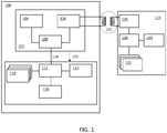
Fig. 1 illustrates a system wherein an exemplary embodiment of the calibration method according to the invention is used. - According to an exemplary embodiment of the invention the method for calibrating a measurement device by means of a calibration device comprises the following steps:
- 1. A user brings the calibration device and the measurement device in close proximity of each other.
- 2. A data communication link is established between the calibration device and the measurement device when they are in close proximity of each other. For example, such a close-proximity data communication link may be enforced by means of near-field communication, as will be explained in detail below.
- 3. The calibration device - comprising at least one sensor - performs a measurement of at least one physical phenomenon pertaining to its environment and sends the results of this measurement to the measurement device via the data communication link.
- 4. The measurement device - comprising one or more sensors, at least one of which senses the same physical phenomenon as the sensor of the calibration device - also performs a measurement of said physical phenomenon.
- 5. The measurement device compares the result of the measurement received from the calibration device with the result of its own measurement of said physical phenomenon.
- 6. The measurement device computes calibration parameters for its sensor using the compared measurement results.
- It is noted that the chronological order of steps (3) and (4) may be interchanged or they may be performed simultaneously. However, it is important that steps (3) and (4) are performed relatively close in time such that the measured physical phenomenon does not change significantly between the respective measurements by the calibration device and the measurement device.
- The close proximity of the calibration device and the measurement device may be enforced by using near-field communication as the data communication link or by using near-field communication to enable said data communication link. Near field communication (NFC) refers to a set of standards for mobile devices to establish radio communication with each other by bringing them into close proximity or by touching them together, usually no more than a few centimeters. Present and anticipated applications of NFC include contactless transactions, data exchange, and simplified setup of more complex communications such as Wi-Fi network setup. Communication is also possible between an NFC interface device and an unpowered chip, such as a passive RFID tag. NFC standards cover communications protocols and data exchange formats and are based on existing radio-frequency identification (RFID) standards including ISO/IEC 14443 and FeliCa. The standards include ISO/IEC 18092 and those defined by the NFC Forum, which was founded in 2004.
- It should be noted that in the context of the present application bringing the calibration device and the measurement device into "close proximity" of each other also includes touching them together in the same way as typical NFC-enabled devices can be touched together - in this case the proximity is as close as physically possible.
- The measurements of the physical phenomenon by both the calibration device and the measurement device take place while these devices are in close proximity of each other and hence while they are exposed to the same physical environment, which should yield the same values for corresponding physical phenomena. It is noted that this condition is typically true for physical phenomena such as temperature, gas concentrations (e.g. humidity and CO2-level) and atmospheric pressure, while it may not be straightforward for direction- and position-sensitive phenomena such as, for example, ambient light level. In the latter case additional measures may be required to compensate for the fact that the physical environments of the calibration device and the measurement device cannot be regarded as substantially the same environment.
- The skilled person will appreciate that it is not strictly necessary that the comparison of the measurements and the computation of the calibration parameters i.e. step (5) and most of step (6) are performed by the measurement device. Alternatively, the measurement device may send its measurements to the calibration device (instead of the other way around) and the calibration device may perform those steps. As a last step, the calibration device will then send the calibration parameters to the measurement device for subsequent storage therein.
- In
Fig. 1 ameasurement device 100 is calibrated by means of acalibration device 124. In a typical smart building environment, for example, there will be many measurement devices, each to be calibrated separately, and only one or just a few portable calibration devices. Themeasurement device 100 comprises anRFID tag 102, one ormore sensors 110, ahost controller 112, amemory 116 and aninterface 114 to convey measurements to the user. - For the sake of the brevity signal conditioning and conversion (e.g. analog-to-digital) circuitry is shown as part of the sensor block. The
interface 114 or means to convey measurements to the user may, for example, be a wired or wireless network interface and/or a display. If the means to convey measurements is a wireless network interface, the measurement device could be a wireless sensor node. As discussed above, the user may be a person, but it may also be an automatic control or monitoring system. - According to this exemplary embodiment, the
calibration device 124 comprises an NFC interface device or anactive RFID device 126, one or more well-calibratedsensors 132, acontroller 128 and amemory unit 130. Again, signal conditioning/conversion is shown as part of the calibratedsensors 132. The skilled person will appreciate that theactual sensors 132 themselves need not be calibrated, but that in such a case thecontroller 128 may compensate for deviations in sensor readouts using calibration parameters stored in thememory unit 130 of thecalibration device 124. In the context of the present application these sensors are also referred to as calibratedsensors 132. - Both the
measurement device 100 and thecalibration device 124 may comprise more than one sensor, each sensor measuring a different physical phenomenon. For example, there could be sensors for measuring ambient temperature, humidity-level, atmospheric pressure and/or CO2-level. Also, again for example, there could be sensors for measuring ambient light and/or radiation temperature, but in that case additional instructions must be supplied to the end-user to make sure both devices are exposed to the same amount of light/radiation temperature while calibrating, which is slightly more elaborate, but still feasible. - Clearly, a sensor of the
measurement device 100 can only be calibrated by means of thecalibration device 124 if a corresponding sensor, i.e. a sensor for measuring the same physical phenomenon, is supported by thecalibration device 124. Thus, thecalibration device 124 and themeasurement device 100 need to have at least one type of sensor in common, for example, they should both have a temperature sensor. - The
RFID tag 102 of themeasurement device 100 comprises anon-volatile memory 104, anRFID interface 106 and atag controller 108. Thetag controller 108 is connected to thehost controller 112 by means of ahost connection 118. Thehost connection 118 enables thehost controller 112 to read from and optionally write into - thenon-volatile memory 104 of theRFID tag 102. TheRFID interface 106 enables thecalibration device 124 to write into and optionally read from thenon-volatile memory 104 in a contactless fashion. Optionally, theRFID tag 102 may be enabled to trigger and/or wake-up the rest of themeasurement device 100 when an interaction with thecalibration device 124 has taken place (which may or may not have changed any or specific contents in the non-volatile memory 104). - According to an exemplary embodiment of the invention the calibration method comprises the following steps:
- 1. A user brings the
calibration device 124 and themeasurement device 100 in close proximity of each other. - 2. The NFC interface device or
active RFID device 126 of thecalibration device 124 detects theRFID interface 106 of theRFID tag 102 of themeasurement device 100 and informs thecontroller 128 of thecalibration device 124, thereby establishing a data communication link. - 3. The
controller 128 of thecalibration device 124 instructs at least onesensor 132 to perform a measurement of a physical phenomenon in the environment and subsequently instructs the NFC interface device oractive RFID device 126 to write the result of this measurement into thenon-volatile memory 104 of theRFID tag 102 of themeasurement device 100 through theRFID interface 106 of theRFID tag 102. - 4. The
host controller 112 of themeasurement device 100 detects that a new measurement value has been written into thenon-volatile memory 104 of theRFID tag 102 and, in response thereto, instructs asensor 110 which measures the same physical phenomenon to perform a measurement of said physical phenomenon as well. - 5. The
host controller 112 of themeasurement device 100 compares the result of the measurement done and communicated by thecalibration device 124 with the result of its own measurement of the same physical phenomenon. - 6. The
host controller 112 of themeasurement device 100 computes calibration parameters for thesensor 110 which measures said physical phenomenon using the compared measurement results and stores these calibration parameters into thememory unit 116 of themeasurement device 100. - During normal operation, the
measurement device 100 uses those calibration parameters to compensate for deviations in sensor readouts when performing measurements. Typically, this implies that thememory unit 116 used for storing the calibration parameters must also be persistent. Therefore, it is an option to use thenon-volatile memory 104 of theRFID tag 102 for this purpose, rather than thememory unit 116. In this case, the calibration parameters are also available for inspection by any NFC-enabled device, which may be beneficial. - According to an alternative embodiment the
RFID tag 102 of themeasurement device 100 may be replaced by an NFC interface device. It may then communicate in peer-to-peer mode with theNFC interface device 126 of thecalibration device 124 or thecalibration device 124 may now contain an RFID tag instead of an NFC interface device, which essentially reverses the roles of thecalibration device 124 and themeasurement device 100 as far as the communication is concerned. However, since the cost and power usage of an RFID tag are normally lower than those of an NFC interface device, implementing an RFID tag in the (many) measurement devices and a full-blown NFC interface device in the (few) calibration devices is usually more attractive. -
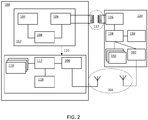
Fig. 2 illustrates a system wherein a further exemplary embodiment of the calibration method according to the invention is used. - The system depicted in
Fig. 2 is similar to the system depicted inFig. 1 . The most notable difference is the fact that the measurement device comprises anRFID tag 102 without a host connection. Thus, theRFID tag 102 is not a so-called "Connected Tag". In this system, no wired connection is provided between thetag controller 108 and thehost controller 112. Therefore, thehost controller 112 has no access to thenon-volatile memory 104 of theRFID tag 102. The NFC interface device oractive RFID device 126 of thecalibration device 124 must be able to read the contents of thenon-volatile memory 104 of theRFID tag 102 of themeasurement device 100 through theRFID interface 106. - A benefit of an
RFID tag 102 without a host connection is that not having a wire between theRFID tag 102 and the rest of themeasurement device 100 lowers cost and simplifies physical design. For example, in this case theRFID tag 102 may take the shape of an RFID-sticker attached to the housing of themeasurement device 100. - As a consequence of not having a host connection, other means for sending the measurement results from the
calibration device 124 to themeasurement device 100 are needed. In order to retain the simplicity of the calibration procedure - so that the end-user merely has to bring themeasurement device 100 and thecalibration device 124 in close proximity of each other - it is preferred for those means to be wireless. Therefore, both themeasurement device 100 and thecalibration device 124 additionally comprise awireless network interface calibration device 124 may support Wi-Fi, themeasurement device 100 may support Zigbee and a gateway could provide a translation. In this example, it is assumed that thewireless network interface 200 of themeasurement device 100 also functions as a means to convey measurement results to a user and therefore no alternative or additional means (such as a display) are shown. Nevertheless, such alternative or additional means would certainly be possible. - According to this exemplary embodiment of the invention the calibration method comprises the following steps:
- 1. A user brings the
calibration device 124 and themeasurement device 100 in close proximity of each other. - 2. The NFC interface device or
active RFID device 126 of thecalibration device 124 detects theRFID tag 102 of themeasurement device 100 and informs thecontroller 128 of thecalibration device 124. Thecontroller 128 of thecalibration device 124 subsequently instructs the NFC interface device oractive RFID device 126 to read contact data, such as a network address, from a predetermined location in thenon-volatile memory 104 of theRFID tag 102 of themeasurement device 100 through theRFID interface 106 of themeasurement device 100. - 3. The
controller 128 of thecalibration device 124 instructs at least onesensor 132 to perform a measurement of a physical phenomenon in the environment and subsequently instructs thewireless network interface 202 of thecalibration device 124 to send the result of said measurement to thewireless network interface 200 of themeasurement device 100 using said contact data. - 4. The
host controller 112 of themeasurement device 100 receives the measurement result through thewireless network interface 200 and, in response, instructs asensor 110 that measures the same physical phenomenon to perform a measurement of said physical phenomenon as well. - 5. The
host controller 112 of themeasurement device 100 compares the result of the measurement done and communicated by thecalibration device 124 with the result of its own measurement of the same physical phenomenon. - 6. The
host controller 112 of themeasurement device 100 computes calibration parameters for thesensor 110 that measures said physical phenomenon using the compared measurement results and stores these calibration parameters into thememory unit 116 of themeasurement device 100. - The contact data of the
measurement device 100 as stored in itsRFID tag 102 may comprise a network address such as a Media Access Control address (MAC address). In addition, the contact data may comprise cryptographic data which enable a secure transfer of the measurement data, i.e. which enable avoiding eavesdropping and tampering. It should be noted that only static information can be stored in theRFID tag 102, because thehost controller 112 has no means to update the data. For example, it makes no sense to store a dynamically allocated network address in theRFID tag 102. The mechanism to set up a connection using static data stored in an RFID tag is known as such. - The skilled person will appreciate that any machine-readable storage medium attached to the housing of the
measurement device 100 may be used to store the contact data. For example, a barcode, a QR-code, or a magnetic strip may be used instead of theRFID tag 102. In those cases, thecalibration device 124 should be equipped with a compatible reader device instead of the NFC interface device oractive RFID device 126. It is important, however, that the reading only takes place when themeasurement device 100 and thecalibration device 124 are in close proximity of each other. - It may be useful to feed back to the end-user that the calibration procedure has or will be completed successfully. Such feedback may, for example, take the form of an audible or visible signal, such as a beep or a blinking LED. If no feedback is given, the end-user knows that something went wrong and can try again or take other steps to resolve the problem. For example, the end-user may not have brought the
measurement device 100 and thecalibration device 124 in sufficiently close proximity of each other or may not have aligned them properly. - The feedback signal may be generated by the
measurement device 100 after having completed step (6). However, in some cases this is not possible because themeasurement device 100 may either not have feedback means (for example an LED or a beeper) or it may not have sufficient energy to generate such a signal. This could, for example, be the case when themeasurement device 100 is an energy-harvesting wireless sensor node. - As an alternative, the feedback signal may be generated by the
calibration device 124 after having completed step (3). At least when thecalibration device 124 can verify that its measurement results have been received correctly by themeasurement device 100, this may give sufficient confidence that the calibration procedure will indeed be completed successfully by themeasurement device 100. However, this alternative does not provide complete certainty that the calibration procedure will be completed successfully. - As yet another alternative, the
measurement device 100 may send a message to thecalibration device 124 after having completed step (6) and thecalibration device 124 may generate the feedback signal after having received this message. It is noted that sending a message may be done by writing into theRFID tag 102 in the system ofFig. 1 or by transmitting over thewireless network interface 200 in the system ofFig. 2 . This alternative has the benefit that the feedback signal is generated only after successful completion of the calibration procedure, while not needing feedback means in themeasurement device 100. - In the system depicted in
Fig. 1 a wake-up signal 120 may be provided from theRFID tag 102 to other parts of themeasurement device 100 as a result of thecalibration device 124 writing the measurement result into thenon-volatile memory 104 of theRFID tag 102 or, in other words, as a result of step (3) having been executed. The wake-up signal causes themeasurement device 100 to proceed with steps (4) through (6). In other words, the wake-up signal is a means by which, at the start of step (4), thehost controller 112 detects the writing of new measurement values. - Similarly, in the system depicted in
Fig. 2 a wake-up signal 120 may be provided from theRFID tag 102 to the rest of themeasurement device 100. This signal may wake-up and trigger thehost controller 112 to start listening to the wireless network in order to receive the measurement result as described in step (4). Specifically, this is useful when themeasurement device 100 is normally in an off or very low-power state and therefore not capable of reading thenon-volatile memory 104 and listening to the network interface, respectively. For example, if themeasurement device 100 is a wireless sensor node it may be in an off or very low-power state when thecalibration device 124 initiates the calibration method. It is beneficial when the user performing the calibration procedure does not have to switch on the wireless sensor node by means of a button, i.e. the procedure is simpler and the cost of a button can be avoided. It is also not acceptable to leave the wireless sensor node in the on state permanently, because that would deplete its energy reserves. It is noted that wireless sensor nodes may use extreme duty cycling in order to operate on harvested energy. As a matter of fact, the time-span between a user pushing the button and subsequently bringing the calibration device and wireless sensor node in close proximity of each other may already be too long - typically seconds, rather than milliseconds - and cause depletion of its energy reserves even before calibration takes place. - By default, the
calibration device 124 will perform measurements using one or more of itssensors 132 and subsequently themeasurement device 100 will perform measurements using the one ormore sensors 110 that measure the same physical phenomena. Normally, thecalibration device 124 uses all of itsavailable sensors 132. Alternatively, it is possible for themeasurement device 100 to measure before or during the measuring process of thecalibration device 124. In that case, themeasurement device 100 will also, typically, perform measurements using all of itssensors 110. - In these cases it may happen that the
calibration device 124 performs measurements for physical phenomena which are not supported by themeasurement device 100 and, vice versa, that themeasurement device 100 may perform measurements that are not supported by thecalibration device 124. Such measurements have no merit, because they do not result in calibration parameters being computed. These measurements without merit may result in unnecessary and unwanted power consumption. This is particularly problematic if the measurement device is an energy-harvesting wireless sensor node. - Furthermore, the
measurement device 100 may set additional requirements for a measurement relating to a specific physical phenomenon as performed by thecalibration device 124. For example, the measurement may require a specific level of accuracy, it may require the measurement data to be encoded in a specific unit (e.g. degrees Celsius) and format, it may require the measurement to be synchronized in time with its own measurement of the same physical phenomenon (e.g. in case of fluctuating conditions in the environment) or it may require a specific spectral profile for an ambient light, radiation temperature, or sound measurement. - Therefore, according to a further exemplary embodiment of the invention, an exchange of capabilities between the
calibration device 124 and themeasurement device 100 may take place during - or directly after - establishing the data communication link, but before the actual measurements take place. - According to a first variant of this embodiment, the
measurement device 100 first advertises the set of physical phenomena that it requires measurements for, together with any additional requirements (e.g. accuracy and unit/format) that it may have for those measurements. If this advertisement is static (i.e. each and every time identical), it may be pre-stored in theRFID tag 102. In the system ofFig. 2 , the contact data is then effectively extended with the set of physical phenomena and the additional requirements. If this advertisement changes depending on, for example, when or how the last calibration for a particular physical phenomenon took place, it has to be written into theRFID tag 102 via thehost connection 118 or via thewireless network interface 200 by themeasurement device 100 before step (3) of the above-described exemplary embodiments of the calibration method takes place. Thecalibration device 124 may subsequently, as part of step (3), limit its measurements to the requested set of physical phenomena while taking the additional requirements into account. Thecalibration device 124 may only measure a subset of the requested set by not performing measurements for physical phenomena that it doesn't support or for which it cannot fulfill the requested additional requirements. - According to a second variant of this embodiment, the
calibration device 124 first advertises the set of physical phenomena that it supports, together with any additional options that it supports for any of those phenomena (e.g. possible accuracy settings, possible units and formats, possible spectral settings, or the option to perform a time-synchronized measurement). This advertisement is done right after establishing the data communication link in step (2) by writing the advertisement into theRFID tag 102 using theRFID connection 122 or by transmitting it over thewireless network 204. Subsequently, themeasurement device 100 will make a selection out of the advertised physical phenomena and the possible additional options, and it will reply to thecalibration device 124 by writing into theRFID tag 102 using thehost connection 118 or by transmitting over thewireless network 204. Subsequently, thecalibration device 124 may only perform measurements for this set and subject to the additional options as part of step (3). - During calibration, it may be of relevance to a
measurement device 100 to be aware of environmental conditions other than the physical phenomena it is capable of measuring itself. For example, sensor results may be influenced by temperature and humidity. In this case, themeasurement device 100 can easily request measurements for those physical phenomena as well from a more capable calibration device. - The data format in which capabilities, i.e. the sets of physical phenomena plus additional requirements or options, are exchanged between the
measurement device 100 and thecalibration device 124 for either variant may be any machine-readable format, for example a specific XML-DTD format, as agreed upon and defined for this purpose. - As mentioned above, in case a physical phenomenon in the environment has the tendency to fluctuate in time relatively quickly - as compared to the duration of the calibration procedure - it may be beneficial for the measurements of that phenomenon by the
calibration device 124 and themeasurement device 100, respectively, to take place substantially simultaneously. There are various ways to implement this synchronization in time. - For example, the
calibration device 124 and themeasurement device 100 may agree upon an absolute moment in time (preferably in the very near future) to actually perform their respective measurements. This requires that thecalibration device 124 and themeasurement device 100 have access to a common (absolute) time base, such as GPS or an atomic clock transmitter. Alternatively, thecalibration device 124 and themeasurement device 100 may synchronize their clocks. It is noted that methods for clock synchronization are known as such. - Furthermore, one of the two devices, i.e. the
measurement device 100 or thecalibration device 124, may send a message "measure now" (parameterized by the applicable physical phenomenon) to the other device and may start measuring immediately. Upon receipt of that message the other device also starts measuring immediately. To ensure that the other device is ready to measure, this message exchange may be preceded by a handshake message exchange to make sure that both devices are ready to measure before the "measure now" message is sent. - In the above-described calibration methods, calibration parameters are computed based on a single measurement by both the
calibration device 124 and themeasurement device 100 for a particular physical phenomenon. This is referred to as single-point calibration. For a more accurate calibration, it may be necessary to compare measurements for the physical phenomenon at two or more values. This is referred to as multi-point calibration. Furthermore, the physical phenomenon is measured at whatever the environmental conditions (i.e. the value of the physical phenomenon) happen to be at the moment of calibration, which is not necessarily the optimal point to perform a (single-point) calibration. - An optional extension of the calibration method according to the invention involves the
measurement device 100 or thecalibration device 124 influencing at least one physical phenomenon in the environment to optimize the calibration point and/or to obtain multiple calibration points. - Thus, according to an exemplary embodiment of the invention, the
measurement device 100 is a wireless sensor node equipped to control lighting, heating, ventilation and/or air-conditioning in a building. Themeasurement device 100 will transmit messages over its wireless network interface to controllers and/or actuators such as lighting luminaries, blinds or heaters to influence the measured physical phenomena in its environment. Whether this is a desirable solution depends on the type of physical phenomenon. For ambient light this may work very well, but for heating, ventilation and air-conditioning this may be less practical. For example, changing the temperature even by a few degrees - which might not even suffice for a proper multi-point calibration - costs a lot of energy and has a strong negative impact on the indoor climate. - Therefore, according to another exemplary embodiment of the invention, the
calibration device 124 is equipped to communicate with a dedicated enclosure (not shown) in which the environmental conditions relating to some of the physical phenomena for which calibration is required can be controlled accurately, quickly, and without unnecessary energy expense or human discomfort. The enclosure may also form part of thecalibration device 124. For example, thecalibration device 124 could be a climate chamber where, for example, temperature, humidity, atmospheric pressure and/or CO2-level can be accurately controlled. In this case, themeasurement device 100 will be physically placed within the enclosure, for example on a pad containing the antenna of the NFC interface device oractive RFID device 126 of thecalibration device 124. Thecalibration device 124, i.e. the climate chamber, may optionally advertise its capabilities for setting calibration points. - In these exemplary embodiments the actuators in the environment and in the climate chamber, respectively, may need some time to reach the next calibration point. For example, it may take some time to heat the climate chamber up from a first temperature calibration point to a next temperature calibration point. In case the
measurement device 100 is an energy-harvesting wireless sensor node or another type ofmeasurement device 100 with a constrained energy supply, it may revert to an off or very low-power state in between subsequent measurements. - As an example, the steps of a method to perform multi-point temperature calibration on a measurement device, i.e. an energy-harvesting wireless sensor node, using a calibration device, i.e. a climate chamber, are outlined below. For the sake of brevity, only the calibration of a single physical phenomenon (i.e. temperature) is discussed. It is noted that this exemplary method combines the use of an RFID tag having a host connection with the optional extensions for end-user feedback (beep), automatic wake-up, capability discovery and multi-point calibration. The steps are as follows:
- 1. An end-user places the wireless sensor node inside the climate chamber on the pad and closes the door of the climate chamber.
- 2. The climate chamber detects the RFID tag of the wireless sensor node and writes its capabilities (capability data) into the RFID tag over the RFID interface. For the purpose of the example, it is assumed that those capabilities include the ability to measure temperature and to influence the temperature over a stated range. Also supported accuracies and units/formats may be expressed as part of the capability data written into the RFID tag.
- 3. The wireless sensor node is woken up from an off or very low-power state by the writing of the capability data into its RFID tag. Subsequently, it reads the capability data from the RFID tag and creates a request to measure the temperature at two or more different calibration points. The request may furthermore include information about required accuracy and unit/format. The wireless sensor node subsequently writes this request into the RFID tag and reverts to the off or very low-power state.
- 4. The climate chamber receives the request from the wireless sensor node by reading from the RFID tag over the RFID interface.
- 5. The climate chamber actuates its heating or cooling device to reach a temperature according to a first requested calibration point. The climate chamber waits until the required temperature is reached.
- 6. The climate chamber then measures the temperature with the required accuracy, encodes it in the required unit/format and writes this measurement data into the RFID tag of the wireless sensor node over the RFID interface.
- 7. The wireless sensor node is woken up from an off or very low-power state by the writing of the measurement data relating to the first calibration point into its RFID tag. Subsequently it reads the measurement data from the RFID tag and performs a temperature measurement using its own temperature sensor and stores both measurements in, for example, its non-volatile memory, and reverts to the off or very low-power state. It should be noted that the non-volatile memory may be really non-volatile or "virtually" non-volatile in the sense that a limited amount of power is fed into it, i.e. in order to retain the state of the memory between subsequent very low-power states of the wireless sensor node, for example.
- 8. Steps (5), (6), and (7) are repeated for a second calibration point and possibly further calibration points. In the last iteration, the wireless sensor node will complete comparing the corresponding measurement results, compute the calibration parameters, store them into its (non-volatile) memory and write a completion message into the RFID tag, before reverting to the off or very low-power state.
- 9. Upon detecting that the completion message has been written into the RFID tag, the climate chamber will output a feedback signal by generating a beep.
- It is noted that in this example the wireless sensor node repeatedly reverts to an off or very low-power state in order to reduce its energy consumption to the bare minimum. It should also be noted that the process of a sensor performing a measurement may be a relatively lengthy procedure, for example compared to the speed at which the host controller executes instructions, particularly if a high accuracy is desired. A sampling or settling time of a hundred microseconds or more is no exception. The host controller and other components of the wireless sensor node could therefore also go to an off or very low-power state while the sensor is performing its measurement autonomously. However, this should be considered as an implementation concern of the sensor node, which is beyond the scope of the present invention. Furthermore, such a technique should also be employed during normal operation of the wireless sensor node and not only during its calibration.
- The above-mentioned embodiments illustrate rather than limit the invention, and the skilled person will be able to design many alternative embodiments without departing from the scope of the appended claims. In the claims, any reference sign placed between parentheses shall not be construed as limiting the claim. The word "comprise(s)" or "comprising" does not exclude the presence of elements or steps other than those listed in a claim. The word "a" or "an" preceding an element does not exclude the presence of a plurality of such elements. The invention may be implemented by means of hardware comprising several distinct elements and/or by means of a suitably programmed processor. In a device claim enumerating several means, several of these means may be embodied by one and the same item of hardware. The mere fact that certain measures are recited in mutually different dependent claims does not indicate that a combination of these measures cannot be used to advantage.
-
- 100
- measurement device
- 102
- RFID tag
- 104
- non-volatile memory unit
- 106
- RFID interface
- 108
- tag controller
- 110
- sensor, signal conditioner and converter
- 112
- host controller
- 114
- interface for conveying measurement result to user
- 116
- memory unit
- 118
- host connection
- 120
- optional host wake-up
- 122
- RFID connection
- 124
- calibration device
- 126
- NFC interface device or active RFID device
- 128
- controller
- 130
- memory unit
- 132
- calibrated sensor, signal conditioner and converter
- 200
- wireless network interface
- 202
- wireless network interface
- 204
- wireless network communication
Claims (18)
- A method for calibrating a measurement device (100) wherein:- a calibration device (124) is brought into close proximity of the measurement device (100) such that the calibration device (124) and the measurement device (100) are exposed to the same physical environment, and such that a data communication link is established between the measurement device (100) and the calibration device (124),wherein the following steps are performed while the calibration device (124) and the measurement device (100) are exposed to the same physical environment:- the calibration device (124) performs a measurement of at least one physical phenomenon;- the measurement device (100) performs a measurement of the same physical phenomenon;- the result of the measurement by the measurement device (100) is compared with the result of the measurement by the calibration device (124);- calibration parameters are automatically computed based on a difference between the result of the measurement by the measurement device (100) and the result of the measurement by the calibration device (124),characterized in that
the close proximity is enforced by using near-field communication as the data communication link or by using near-field communication to enable said data communication link. - A method as claimed in claim 1, wherein the calibration device (124) sends the result of its measurement to the measurement device (100), and wherein the measurement device (100) compares the result of the measurement by the measurement device (100) and the result of the measurement by the calibration device (124) and computes said calibration parameters.
- A method as claimed in claim 2, wherein the measurement device (100) comprises an RFID tag (102) and a host controller (112) which are connected to each other via a host connection (118), wherein the calibration device (124) comprises an NFC interface device or an active RFID device (126), wherein said data communication link is established between the RFID tag (102) and the NFC interface device or active RFID device (126), and wherein the result of the measurement by the calibration device (124) is sent to the measurement device (100) by writing said result into the RFID tag (102) via said data communication link.
- A method as claimed in claim 2, wherein the measurement device (100) comprises an NFC interface device and a host controller (112) which are connected to each other via a host connection (118), wherein the calibration device (124) comprises a further NFC interface device, wherein said data communication link is established between the NFC interface device and the further NFC interface device, and wherein the result of the measurement by the calibration device (124) is sent to the measurement device (100) by sending said result to the NFC interface device via said data communication link.
- A method as claimed in claim 1, wherein the measurement device (100) sends the result of its measurement to the calibration device (124), wherein the calibration device (124) compares the result of the measurement by the measurement device (100) and the result of the measurement by the calibration device (124) and computes said calibration parameters, and wherein the calibration device (124) subsequently sends the calibration parameters to the measurement device (100).
- A method as claimed in claim 1, 2 or 5, wherein the measurement device (100) comprises a machine-readable storage medium which comprises contact data of the measurement device (100), wherein the calibration device (124) comprises a reader device for contactless reading of said contact data from the machine-readable storage medium, and wherein the calibration device (124) establishes said data communication link via a wireless network interface (202) using said contact data.
- A method as claimed in claim 6, wherein the machine-readable storage medium is an RFID tag.
- A method as claimed in claim 6, wherein the machine-readable storage medium further comprises cryptographic data for enabling secure communication via said wireless network interface (202).
- A method as claimed in any preceding claim, wherein the measurement device (100) and the calibration device (124) comprise respective sensors (110, 132) for measuring said physical phenomenon.
- A method as claimed in any preceding claim, wherein the measurement device (100) is a wireless sensor node for use in a control system.
- A method as claimed in any preceding claim, wherein a feedback signal is generated when the calibration has finished or when the calibration is expected to finish.
- A method as claimed in claim 3 or 7, wherein said RFID tag (102) wakes up other parts of the measurement device (100) after the data communication link has been established, such that the measurement device (100) may perform subsequent steps of the method.
- A method as claimed in any preceding claim, wherein an exchange of capability data representing at least a set of physical phenomena takes place between the measurement device (100) and the calibration device (124) before the respective measurements of the physical phenomenon are performed.
- A method as claimed in any preceding claim, wherein the measurement of the physical phenomenon by the calibration device (124) and the measurement of the same physical phenomenon by the measurement device (100) are synchronized in time.
- A method as claimed in any preceding claim, wherein the measurement device (100) or the calibration device (124) influences the physical phenomenon in order to optimize a calibration point and/or to obtain multiple calibration points.
- A computer program product comprising program elements executable by the measurement device (100) or the calibration device (124), wherein each program element comprises program instructions which, when being executed by the measurement device (100) and the calibration device (124), respectively, cause said measurement device (100) and calibration device (124) to carry out or control respective steps of a method as claimed in any one of claims 1 to 15.
- A calibration device (124) for use in a method as claimed in any one of claims 1 to 15.
- A measurement device (100) for use in a method as claimed in any one of claims 1 to 15.
Priority Applications (3)
| Application Number | Priority Date | Filing Date | Title |
|---|---|---|---|
| EP12154988.5A EP2626755B1 (en) | 2012-02-10 | 2012-02-10 | Calibration method, calibration device and measurement device |
| US13/762,244 US10302468B2 (en) | 2012-02-10 | 2013-02-07 | Calibration method, calibration device and measurement device |
| CN201310050706.4A CN103256954B (en) | 2012-02-10 | 2013-02-08 | Calibration method, calibration device and measurement device |
Applications Claiming Priority (1)
| Application Number | Priority Date | Filing Date | Title |
|---|---|---|---|
| EP12154988.5A EP2626755B1 (en) | 2012-02-10 | 2012-02-10 | Calibration method, calibration device and measurement device |
Publications (2)
| Publication Number | Publication Date |
|---|---|
| EP2626755A1 EP2626755A1 (en) | 2013-08-14 |
| EP2626755B1 true EP2626755B1 (en) | 2019-04-10 |
Family
ID=45562890
Family Applications (1)
| Application Number | Title | Priority Date | Filing Date |
|---|---|---|---|
| EP12154988.5A Active EP2626755B1 (en) | 2012-02-10 | 2012-02-10 | Calibration method, calibration device and measurement device |
Country Status (3)
| Country | Link |
|---|---|
| US (1) | US10302468B2 (en) |
| EP (1) | EP2626755B1 (en) |
| CN (1) | CN103256954B (en) |
Families Citing this family (64)
| Publication number | Priority date | Publication date | Assignee | Title |
|---|---|---|---|---|
| US8097926B2 (en) | 2008-10-07 | 2012-01-17 | Mc10, Inc. | Systems, methods, and devices having stretchable integrated circuitry for sensing and delivering therapy |
| US9123614B2 (en) | 2008-10-07 | 2015-09-01 | Mc10, Inc. | Methods and applications of non-planar imaging arrays |
| US9289132B2 (en) | 2008-10-07 | 2016-03-22 | Mc10, Inc. | Catheter balloon having stretchable integrated circuitry and sensor array |
| US8389862B2 (en) | 2008-10-07 | 2013-03-05 | Mc10, Inc. | Extremely stretchable electronics |
| US9723122B2 (en) | 2009-10-01 | 2017-08-01 | Mc10, Inc. | Protective cases with integrated electronics |
| EP2681538B1 (en) | 2011-03-11 | 2019-03-06 | Mc10, Inc. | Integrated devices to facilitate quantitative assays and diagnostics |
| KR102000302B1 (en) | 2011-05-27 | 2019-07-15 | 엠씨10, 인크 | Electronic, optical and/or mechanical apparatus and systems and methods for fabricating same |
| DE112012003250T5 (en) | 2011-08-05 | 2014-04-30 | Mc10, Inc. | Catheter Balloon method and apparatus using sensing elements |
| US9757050B2 (en) | 2011-08-05 | 2017-09-12 | Mc10, Inc. | Catheter balloon employing force sensing elements |
| WO2013033724A1 (en) | 2011-09-01 | 2013-03-07 | Mc10, Inc. | Electronics for detection of a condition of tissue |
| EP2573948B1 (en) | 2011-09-23 | 2017-03-15 | Nxp B.V. | System and method for commissioning devices |
| JP6277130B2 (en) | 2011-10-05 | 2018-02-14 | エムシーテン、インコーポレイテッド | Medical device and method of manufacturing the same |
| EP2602677B1 (en) | 2011-12-05 | 2018-02-21 | Nxp B.V. | Localization method, computer program product and localization device |
| EP2624081B1 (en) | 2012-01-31 | 2018-01-10 | Nxp B.V. | Configuration method, configuration device, computer program product and control system |
| EP2650820B1 (en) | 2012-04-12 | 2014-10-08 | Nxp B.V. | Control method and computer program product |
| EP2665235B1 (en) | 2012-05-15 | 2016-01-06 | Nxp B.V. | Method for establishing secure communication between nodes in a network, network node, key manager, installation device and computer program product |
| US9226402B2 (en) | 2012-06-11 | 2015-12-29 | Mc10, Inc. | Strain isolation structures for stretchable electronics |
| US9295842B2 (en) | 2012-07-05 | 2016-03-29 | Mc10, Inc. | Catheter or guidewire device including flow sensing and use thereof |
| JP2015521894A (en) | 2012-07-05 | 2015-08-03 | エムシー10 インコーポレイテッドMc10,Inc. | Catheter device including flow sensing |
| EP2704365B1 (en) | 2012-08-31 | 2016-02-03 | Nxp B.V. | Method for establishing control relationships, configuration device, networked device and computer program product |
| US9082025B2 (en) | 2012-10-09 | 2015-07-14 | Mc10, Inc. | Conformal electronics integrated with apparel |
| US9171794B2 (en) | 2012-10-09 | 2015-10-27 | Mc10, Inc. | Embedding thin chips in polymer |
| US9706647B2 (en) | 2013-05-14 | 2017-07-11 | Mc10, Inc. | Conformal electronics including nested serpentine interconnects |
| JP2016527649A (en) | 2013-08-05 | 2016-09-08 | エムシー10 インコーポレイテッドMc10,Inc. | Flexible temperature sensor including compatible electronics |
| JP2016532468A (en) | 2013-10-07 | 2016-10-20 | エムシー10 インコーポレイテッドMc10,Inc. | Conformal sensor system for detection and analysis |
| GB2519120B (en) * | 2013-10-10 | 2017-10-18 | Abb Ltd | Methods and apparatus relating to measurement instruments |
| EP3071096A4 (en) | 2013-11-22 | 2017-08-09 | Mc10, Inc. | Conformal sensor systems for sensing and analysis of cardiac activity |
| US20150173154A1 (en) * | 2013-12-17 | 2015-06-18 | Nxp B.V. | Commissioning method and apparatus |
| CA2931096A1 (en) * | 2014-01-03 | 2015-07-09 | Mc10, Inc. | Integrated devices for low power quantitative measurements |
| WO2015103580A2 (en) | 2014-01-06 | 2015-07-09 | Mc10, Inc. | Encapsulated conformal electronic systems and devices, and methods of making and using the same |
| JP6637896B2 (en) | 2014-03-04 | 2020-01-29 | エムシー10 インコーポレイテッドMc10,Inc. | Conformal IC device with flexible multi-part encapsulated housing for electronic devices |
| WO2015138712A1 (en) | 2014-03-12 | 2015-09-17 | Mc10, Inc. | Quantification of a change in assay |
| US11054289B2 (en) | 2014-06-11 | 2021-07-06 | At&T Intellectual Property I, L.P. | Sensor calibration |
| US9899330B2 (en) | 2014-10-03 | 2018-02-20 | Mc10, Inc. | Flexible electronic circuits with embedded integrated circuit die |
| US10297572B2 (en) | 2014-10-06 | 2019-05-21 | Mc10, Inc. | Discrete flexible interconnects for modules of integrated circuits |
| USD781270S1 (en) | 2014-10-15 | 2017-03-14 | Mc10, Inc. | Electronic device having antenna |
| US20160169716A1 (en) * | 2014-12-15 | 2016-06-16 | General Electric Company | System and method for on-site measurement apparatus calibration |
| US20180010935A1 (en) * | 2014-12-19 | 2018-01-11 | Information is Power Pty Ltd. | System and method for identifying and calibrating a sensor |
| EP3059919A1 (en) | 2015-02-19 | 2016-08-24 | Nxp B.V. | Method and system for facilitating network joining |
| US10477354B2 (en) | 2015-02-20 | 2019-11-12 | Mc10, Inc. | Automated detection and configuration of wearable devices based on on-body status, location, and/or orientation |
| WO2016140961A1 (en) | 2015-03-02 | 2016-09-09 | Mc10, Inc. | Perspiration sensor |
| CN104792457B (en) * | 2015-04-08 | 2017-05-17 | 无锡必创传感科技有限公司 | Correcting device and method of pressure module |
| EP3086585B1 (en) | 2015-04-23 | 2019-12-11 | Nxp B.V. | Method and system for securing data communicated in a network |
| DE102015210880A1 (en) * | 2015-06-15 | 2016-12-15 | Sentronic GmbH Gesellschaft für optische Meßsysteme | Measuring device for determining physical properties, chemical properties, biological properties and / or substances of the environment of at least one pick-up or the at least one pick-up as part of the measuring device |
| US10653332B2 (en) | 2015-07-17 | 2020-05-19 | Mc10, Inc. | Conductive stiffener, method of making a conductive stiffener, and conductive adhesive and encapsulation layers |
| US10709384B2 (en) | 2015-08-19 | 2020-07-14 | Mc10, Inc. | Wearable heat flux devices and methods of use |
| US9996712B2 (en) * | 2015-09-02 | 2018-06-12 | Endotronix, Inc. | Self test device and method for wireless sensor reader |
| DE102015115614A1 (en) * | 2015-09-16 | 2017-03-16 | Krohne Messtechnik Gmbh | Measuring device and measuring arrangement |
| US10300371B2 (en) | 2015-10-01 | 2019-05-28 | Mc10, Inc. | Method and system for interacting with a virtual environment |
| US10532211B2 (en) | 2015-10-05 | 2020-01-14 | Mc10, Inc. | Method and system for neuromodulation and stimulation |
| WO2017066099A1 (en) * | 2015-10-12 | 2017-04-20 | Nextnav, Llc | Designing a calibration system for use in calibrating unstable sensors |
| WO2017147053A1 (en) | 2016-02-22 | 2017-08-31 | Mc10, Inc. | System, device, and method for coupled hub and sensor node on-body acquisition of sensor information |
| EP3420732B8 (en) | 2016-02-22 | 2020-12-30 | Medidata Solutions, Inc. | System, devices, and method for on-body data and power transmission |
| CN109310340A (en) | 2016-04-19 | 2019-02-05 | Mc10股份有限公司 | For measuring the method and system of sweat |
| US10447347B2 (en) | 2016-08-12 | 2019-10-15 | Mc10, Inc. | Wireless charger and high speed data off-loader |
| CN109983327A (en) * | 2016-12-01 | 2019-07-05 | 霍尼韦尔国际公司 | Total dissolved solid pick up calibration equipment, method and system |
| CN106855433B (en) * | 2016-12-26 | 2019-01-22 | 中国科学院长春光学精密机械与物理研究所 | A kind of method and device of imaging spectrometer auto-scaling |
| EP3583701B1 (en) * | 2017-02-16 | 2022-01-19 | Watlow Electric Manufacturing Company | Compact modular wireless sensor |
| CN109855667B (en) * | 2018-12-21 | 2022-02-22 | 金卡智能集团股份有限公司 | Error calibration method suitable for different gauges |
| DE102019127380A1 (en) * | 2019-10-10 | 2021-04-15 | Endress+Hauser Conducta Gmbh+Co. Kg | Sensor system for the mobile acquisition of at least one measured value and measuring method for such a sensor system |
| CN113497660B (en) * | 2020-03-19 | 2024-05-03 | 普源精电科技股份有限公司 | Signal source synchronization system, method, equipment and channel synchronization method |
| FR3116168B1 (en) | 2020-11-12 | 2023-05-12 | St Microelectronics Rousset | Calibration of an on-time of a circuit |
| CN115225541B (en) * | 2022-05-12 | 2023-05-09 | 中国电子技术标准化研究院 | Calibration method, device and storage medium of self-organizing network test system |
| CN116026437A (en) * | 2023-03-29 | 2023-04-28 | 青岛鼎信通讯科技有限公司 | NFC communication-based ultrasonic water meter calibration method |
Family Cites Families (29)
| Publication number | Priority date | Publication date | Assignee | Title |
|---|---|---|---|---|
| US6233532B1 (en) * | 1998-01-14 | 2001-05-15 | Dover Associates, Inc. | Sensor assembly |
| ATE442573T1 (en) * | 2001-11-13 | 2009-09-15 | Nokia Corp | METHOD, DEVICE AND SYSTEM FOR CALIBRATION OF ANGLE RATE MEASUREMENT SENSORS |
| US6667690B2 (en) * | 2002-01-22 | 2003-12-23 | Carrier Corporation | System and method for configuration of HVAC network |
| US6998247B2 (en) | 2002-03-08 | 2006-02-14 | Sensys Medical, Inc. | Method and apparatus using alternative site glucose determinations to calibrate and maintain noninvasive and implantable analyzers |
| EP1349114A3 (en) | 2002-03-19 | 2011-06-15 | Canon Kabushiki Kaisha | Sensor calibration apparatus, sensor calibration method, program, storage medium, information processing method, and information processing apparatus |
| US6662130B1 (en) | 2002-06-13 | 2003-12-09 | Southwest Research Institute | Systems and methods for calibrating a distorted signal with another signal of known calibration |
| US6795786B2 (en) * | 2002-12-31 | 2004-09-21 | Intel Corporation | Robotic sensor calibration system |
| US7299082B2 (en) * | 2003-10-31 | 2007-11-20 | Abbott Diabetes Care, Inc. | Method of calibrating an analyte-measurement device, and associated methods, devices and systems |
| US7165722B2 (en) * | 2004-03-10 | 2007-01-23 | Microsoft Corporation | Method and system for communicating with identification tags |
| KR100663584B1 (en) * | 2004-09-08 | 2007-01-02 | 삼성전자주식회사 | Apparatus and method for controlling power at sleep mode in mobile terminal |
| JP5032321B2 (en) * | 2004-08-31 | 2012-09-26 | ライフスキャン・スコットランド・リミテッド | Manufacturing method of automatic calibration sensor |
| US7477950B2 (en) * | 2004-09-28 | 2009-01-13 | Dymocom, Inc. | Method and system for controlling a network of water appliances |
| ATE450024T1 (en) | 2005-06-29 | 2009-12-15 | Michelin Rech Tech | RFID FOR STORING SAW CALIBRATION COEFFICIENTS |
| US7289924B2 (en) * | 2005-07-20 | 2007-10-30 | Honeywell International Inc. | Self-calibrating sensor |
| US7287699B2 (en) * | 2005-08-05 | 2007-10-30 | Honeywell International Inc. | Sensor calibration method and systems |
| US8472986B2 (en) * | 2005-09-21 | 2013-06-25 | Buckyball Mobile, Inc. | Method and system of optimizing context-data acquisition by a mobile device |
| US8988223B2 (en) * | 2005-12-09 | 2015-03-24 | Tego Inc. | RFID drive management facility |
| DE102006024743A1 (en) | 2006-05-26 | 2007-12-06 | Siemens Ag | Transducer for e.g. determining and influencing pressure, has memory storing calibration data of sensor and/or user-specific configuration data of transducer, where data are readable from memory and/or written in memory by radio interface |
| KR101239482B1 (en) * | 2007-03-23 | 2013-03-06 | 퀄컴 인코포레이티드 | Multi-sensor data collection and/or processing |
| US8217782B2 (en) * | 2007-05-24 | 2012-07-10 | Rosemount Inc. | Industrial field device with reduced power consumption |
| DE102007024423B4 (en) * | 2007-05-25 | 2019-09-12 | Cooper Crouse-Hinds Gmbh | Recording device and method for monitoring device parameters |
| US8264408B2 (en) * | 2007-11-20 | 2012-09-11 | Nokia Corporation | User-executable antenna array calibration |
| EP2138919B1 (en) * | 2008-06-27 | 2013-12-25 | ABB Research Ltd. | Wireless field device and method to configure same |
| US9627913B2 (en) * | 2008-08-18 | 2017-04-18 | Nxp B.V. | Mobile device to control a charge pad system |
| CN102160004B (en) | 2008-09-22 | 2014-11-05 | Nxp股份有限公司 | Automatic address selection for controllable devices |
| US20110264543A1 (en) * | 2010-04-26 | 2011-10-27 | Ebay Inc. | Reverse payment flow |
| EP2573948B1 (en) | 2011-09-23 | 2017-03-15 | Nxp B.V. | System and method for commissioning devices |
| EP2602677B1 (en) | 2011-12-05 | 2018-02-21 | Nxp B.V. | Localization method, computer program product and localization device |
| EP2624081B1 (en) | 2012-01-31 | 2018-01-10 | Nxp B.V. | Configuration method, configuration device, computer program product and control system |
-
2012
- 2012-02-10 EP EP12154988.5A patent/EP2626755B1/en active Active
-
2013
- 2013-02-07 US US13/762,244 patent/US10302468B2/en active Active
- 2013-02-08 CN CN201310050706.4A patent/CN103256954B/en active Active
Non-Patent Citations (1)
| Title |
|---|
| None * |
Also Published As
| Publication number | Publication date |
|---|---|
| US20130211761A1 (en) | 2013-08-15 |
| CN103256954A (en) | 2013-08-21 |
| EP2626755A1 (en) | 2013-08-14 |
| US10302468B2 (en) | 2019-05-28 |
| CN103256954B (en) | 2015-06-03 |
Similar Documents
| Publication | Publication Date | Title |
|---|---|---|
| EP2626755B1 (en) | Calibration method, calibration device and measurement device | |
| JP6197881B2 (en) | Communication node, system, and synchronization method | |
| US20180103346A1 (en) | System and method for multi-beacon interaction and management | |
| EP2704365B1 (en) | Method for establishing control relationships, configuration device, networked device and computer program product | |
| US10070504B2 (en) | Associating wireless control devices | |
| US20160119744A1 (en) | Method for monitoring photovoltaic power generation using rtu, and wireless rtu device thereof | |
| Sisinni et al. | Design and implementation of a wireless sensor network for temperature sensing in hostile environments | |
| CN108431830B (en) | Display device with controllable processing stages | |
| Taştan et al. | An Internet of Things based air conditioning and lighting control system for smart home | |
| TWI475491B (en) | System and method for updating electronic shelf labels and updating apparatus and method of an electronic shelf label | |
| EP2566109A2 (en) | Information processing apparatus and information processing program | |
| CN109661802A (en) | Share the environmental data used for client device | |
| US20210076328A1 (en) | Sensor device and secured wireless communication protocol for air quality sensor devices | |
| KR20150072934A (en) | Electronic tag, electronic shelf label system, and operation method of the same | |
| KR102061166B1 (en) | Method and apparatus for sensing | |
| JP2019517172A (en) | NFC-enabled wireless process communication gateway | |
| Ferrigno et al. | A Bluetooth-based proposal of instrument wireless interface | |
| JP5952978B1 (en) | Electronic device operating environment setting system, operating environment setting method, and operating environment setting program | |
| JP4866453B2 (en) | Wireless communication method, wireless terminal device, and wireless communication system | |
| JP2016005172A (en) | Mesh radio communication system, radio communication method and radio unit | |
| CN104956235A (en) | Method and apparatus for determining a change in position of a location marker | |
| Pierleoni et al. | Indoor localization system for AAL over IPv6 WSN | |
| TWI595422B (en) | Electronic tag, display updating system thereof and operation method thereof | |
| KR101452692B1 (en) | Iot-based termination apparatus of assembly type | |
| JP2014158112A (en) | Zigbee terminal, home gateway, zigbee network, power saving method and program |
Legal Events
| Date | Code | Title | Description |
|---|---|---|---|
| PUAI | Public reference made under article 153(3) epc to a published international application that has entered the european phase |
Free format text: ORIGINAL CODE: 0009012 |
|
| AK | Designated contracting states |
Kind code of ref document: A1 Designated state(s): AL AT BE BG CH CY CZ DE DK EE ES FI FR GB GR HR HU IE IS IT LI LT LU LV MC MK MT NL NO PL PT RO RS SE SI SK SM TR |
|
| AX | Request for extension of the european patent |
Extension state: BA ME |
|
| 17P | Request for examination filed |
Effective date: 20131031 |
|
| RBV | Designated contracting states (corrected) |
Designated state(s): AL AT BE BG CH CY CZ DE DK EE ES FI FR GB GR HR HU IE IS IT LI LT LU LV MC MK MT NL NO PL PT RO RS SE SI SK SM TR |
|
| 17Q | First examination report despatched |
Effective date: 20140704 |
|
| RIC1 | Information provided on ipc code assigned before grant |
Ipc: G05B 19/042 20060101AFI20180713BHEP Ipc: G01D 18/00 20060101ALI20180713BHEP Ipc: G01D 21/00 20060101ALI20180713BHEP Ipc: G06F 17/00 20060101ALI20180713BHEP |
|
| GRAP | Despatch of communication of intention to grant a patent |
Free format text: ORIGINAL CODE: EPIDOSNIGR1 |
|
| STAA | Information on the status of an ep patent application or granted ep patent |
Free format text: STATUS: GRANT OF PATENT IS INTENDED |
|
| INTG | Intention to grant announced |
Effective date: 20180907 |
|
| GRAS | Grant fee paid |
Free format text: ORIGINAL CODE: EPIDOSNIGR3 |
|
| GRAA | (expected) grant |
Free format text: ORIGINAL CODE: 0009210 |
|
| STAA | Information on the status of an ep patent application or granted ep patent |
Free format text: STATUS: THE PATENT HAS BEEN GRANTED |
|
| AK | Designated contracting states |
Kind code of ref document: B1 Designated state(s): AL AT BE BG CH CY CZ DE DK EE ES FI FR GB GR HR HU IE IS IT LI LT LU LV MC MK MT NL NO PL PT RO RS SE SI SK SM TR |
|
| REG | Reference to a national code |
Ref country code: GB Ref legal event code: FG4D |
|
| REG | Reference to a national code |
Ref country code: CH Ref legal event code: EP Ref country code: AT Ref legal event code: REF Ref document number: 1119541 Country of ref document: AT Kind code of ref document: T Effective date: 20190415 |
|
| REG | Reference to a national code |
Ref country code: IE Ref legal event code: FG4D |
|
| REG | Reference to a national code |
Ref country code: DE Ref legal event code: R096 Ref document number: 602012058732 Country of ref document: DE |
|
| REG | Reference to a national code |
Ref country code: NL Ref legal event code: MP Effective date: 20190410 |
|
| REG | Reference to a national code |
Ref country code: LT Ref legal event code: MG4D |
|
| REG | Reference to a national code |
Ref country code: AT Ref legal event code: MK05 Ref document number: 1119541 Country of ref document: AT Kind code of ref document: T Effective date: 20190410 |
|
| PG25 | Lapsed in a contracting state [announced via postgrant information from national office to epo] |
Ref country code: NL Free format text: LAPSE BECAUSE OF FAILURE TO SUBMIT A TRANSLATION OF THE DESCRIPTION OR TO PAY THE FEE WITHIN THE PRESCRIBED TIME-LIMIT Effective date: 20190410 |
|
| PG25 | Lapsed in a contracting state [announced via postgrant information from national office to epo] |
Ref country code: SE Free format text: LAPSE BECAUSE OF FAILURE TO SUBMIT A TRANSLATION OF THE DESCRIPTION OR TO PAY THE FEE WITHIN THE PRESCRIBED TIME-LIMIT Effective date: 20190410 Ref country code: ES Free format text: LAPSE BECAUSE OF FAILURE TO SUBMIT A TRANSLATION OF THE DESCRIPTION OR TO PAY THE FEE WITHIN THE PRESCRIBED TIME-LIMIT Effective date: 20190410 Ref country code: LT Free format text: LAPSE BECAUSE OF FAILURE TO SUBMIT A TRANSLATION OF THE DESCRIPTION OR TO PAY THE FEE WITHIN THE PRESCRIBED TIME-LIMIT Effective date: 20190410 Ref country code: PT Free format text: LAPSE BECAUSE OF FAILURE TO SUBMIT A TRANSLATION OF THE DESCRIPTION OR TO PAY THE FEE WITHIN THE PRESCRIBED TIME-LIMIT Effective date: 20190910 Ref country code: AL Free format text: LAPSE BECAUSE OF FAILURE TO SUBMIT A TRANSLATION OF THE DESCRIPTION OR TO PAY THE FEE WITHIN THE PRESCRIBED TIME-LIMIT Effective date: 20190410 Ref country code: NO Free format text: LAPSE BECAUSE OF FAILURE TO SUBMIT A TRANSLATION OF THE DESCRIPTION OR TO PAY THE FEE WITHIN THE PRESCRIBED TIME-LIMIT Effective date: 20190710 Ref country code: HR Free format text: LAPSE BECAUSE OF FAILURE TO SUBMIT A TRANSLATION OF THE DESCRIPTION OR TO PAY THE FEE WITHIN THE PRESCRIBED TIME-LIMIT Effective date: 20190410 Ref country code: FI Free format text: LAPSE BECAUSE OF FAILURE TO SUBMIT A TRANSLATION OF THE DESCRIPTION OR TO PAY THE FEE WITHIN THE PRESCRIBED TIME-LIMIT Effective date: 20190410 |
|
| PG25 | Lapsed in a contracting state [announced via postgrant information from national office to epo] |
Ref country code: PL Free format text: LAPSE BECAUSE OF FAILURE TO SUBMIT A TRANSLATION OF THE DESCRIPTION OR TO PAY THE FEE WITHIN THE PRESCRIBED TIME-LIMIT Effective date: 20190410 Ref country code: GR Free format text: LAPSE BECAUSE OF FAILURE TO SUBMIT A TRANSLATION OF THE DESCRIPTION OR TO PAY THE FEE WITHIN THE PRESCRIBED TIME-LIMIT Effective date: 20190711 Ref country code: LV Free format text: LAPSE BECAUSE OF FAILURE TO SUBMIT A TRANSLATION OF THE DESCRIPTION OR TO PAY THE FEE WITHIN THE PRESCRIBED TIME-LIMIT Effective date: 20190410 Ref country code: BG Free format text: LAPSE BECAUSE OF FAILURE TO SUBMIT A TRANSLATION OF THE DESCRIPTION OR TO PAY THE FEE WITHIN THE PRESCRIBED TIME-LIMIT Effective date: 20190710 Ref country code: RS Free format text: LAPSE BECAUSE OF FAILURE TO SUBMIT A TRANSLATION OF THE DESCRIPTION OR TO PAY THE FEE WITHIN THE PRESCRIBED TIME-LIMIT Effective date: 20190410 |
|
| PG25 | Lapsed in a contracting state [announced via postgrant information from national office to epo] |
Ref country code: IS Free format text: LAPSE BECAUSE OF FAILURE TO SUBMIT A TRANSLATION OF THE DESCRIPTION OR TO PAY THE FEE WITHIN THE PRESCRIBED TIME-LIMIT Effective date: 20190810 Ref country code: AT Free format text: LAPSE BECAUSE OF FAILURE TO SUBMIT A TRANSLATION OF THE DESCRIPTION OR TO PAY THE FEE WITHIN THE PRESCRIBED TIME-LIMIT Effective date: 20190410 |
|
| REG | Reference to a national code |
Ref country code: DE Ref legal event code: R097 Ref document number: 602012058732 Country of ref document: DE |
|
| PG25 | Lapsed in a contracting state [announced via postgrant information from national office to epo] |
Ref country code: DK Free format text: LAPSE BECAUSE OF FAILURE TO SUBMIT A TRANSLATION OF THE DESCRIPTION OR TO PAY THE FEE WITHIN THE PRESCRIBED TIME-LIMIT Effective date: 20190410 Ref country code: EE Free format text: LAPSE BECAUSE OF FAILURE TO SUBMIT A TRANSLATION OF THE DESCRIPTION OR TO PAY THE FEE WITHIN THE PRESCRIBED TIME-LIMIT Effective date: 20190410 Ref country code: SK Free format text: LAPSE BECAUSE OF FAILURE TO SUBMIT A TRANSLATION OF THE DESCRIPTION OR TO PAY THE FEE WITHIN THE PRESCRIBED TIME-LIMIT Effective date: 20190410 Ref country code: RO Free format text: LAPSE BECAUSE OF FAILURE TO SUBMIT A TRANSLATION OF THE DESCRIPTION OR TO PAY THE FEE WITHIN THE PRESCRIBED TIME-LIMIT Effective date: 20190410 Ref country code: CZ Free format text: LAPSE BECAUSE OF FAILURE TO SUBMIT A TRANSLATION OF THE DESCRIPTION OR TO PAY THE FEE WITHIN THE PRESCRIBED TIME-LIMIT Effective date: 20190410 |
|
| PLBE | No opposition filed within time limit |
Free format text: ORIGINAL CODE: 0009261 |
|
| STAA | Information on the status of an ep patent application or granted ep patent |
Free format text: STATUS: NO OPPOSITION FILED WITHIN TIME LIMIT |
|
| PG25 | Lapsed in a contracting state [announced via postgrant information from national office to epo] |
Ref country code: IT Free format text: LAPSE BECAUSE OF FAILURE TO SUBMIT A TRANSLATION OF THE DESCRIPTION OR TO PAY THE FEE WITHIN THE PRESCRIBED TIME-LIMIT Effective date: 20190410 Ref country code: SM Free format text: LAPSE BECAUSE OF FAILURE TO SUBMIT A TRANSLATION OF THE DESCRIPTION OR TO PAY THE FEE WITHIN THE PRESCRIBED TIME-LIMIT Effective date: 20190410 |
|
| 26N | No opposition filed |
Effective date: 20200113 |
|
| PG25 | Lapsed in a contracting state [announced via postgrant information from national office to epo] |
Ref country code: TR Free format text: LAPSE BECAUSE OF FAILURE TO SUBMIT A TRANSLATION OF THE DESCRIPTION OR TO PAY THE FEE WITHIN THE PRESCRIBED TIME-LIMIT Effective date: 20190410 |
|
| PG25 | Lapsed in a contracting state [announced via postgrant information from national office to epo] |
Ref country code: SI Free format text: LAPSE BECAUSE OF FAILURE TO SUBMIT A TRANSLATION OF THE DESCRIPTION OR TO PAY THE FEE WITHIN THE PRESCRIBED TIME-LIMIT Effective date: 20190410 |
|
| REG | Reference to a national code |
Ref country code: CH Ref legal event code: PL |
|
| GBPC | Gb: european patent ceased through non-payment of renewal fee |
Effective date: 20200210 |
|
| REG | Reference to a national code |
Ref country code: BE Ref legal event code: MM Effective date: 20200229 |
|
| PG25 | Lapsed in a contracting state [announced via postgrant information from national office to epo] |
Ref country code: MC Free format text: LAPSE BECAUSE OF FAILURE TO SUBMIT A TRANSLATION OF THE DESCRIPTION OR TO PAY THE FEE WITHIN THE PRESCRIBED TIME-LIMIT Effective date: 20190410 Ref country code: LU Free format text: LAPSE BECAUSE OF NON-PAYMENT OF DUE FEES Effective date: 20200210 |
|
| PG25 | Lapsed in a contracting state [announced via postgrant information from national office to epo] |
Ref country code: LI Free format text: LAPSE BECAUSE OF NON-PAYMENT OF DUE FEES Effective date: 20200229 Ref country code: CH Free format text: LAPSE BECAUSE OF NON-PAYMENT OF DUE FEES Effective date: 20200229 |
|
| PG25 | Lapsed in a contracting state [announced via postgrant information from national office to epo] |
Ref country code: IE Free format text: LAPSE BECAUSE OF NON-PAYMENT OF DUE FEES Effective date: 20200210 Ref country code: GB Free format text: LAPSE BECAUSE OF NON-PAYMENT OF DUE FEES Effective date: 20200210 |
|
| PG25 | Lapsed in a contracting state [announced via postgrant information from national office to epo] |
Ref country code: BE Free format text: LAPSE BECAUSE OF NON-PAYMENT OF DUE FEES Effective date: 20200229 |
|
| PG25 | Lapsed in a contracting state [announced via postgrant information from national office to epo] |
Ref country code: MT Free format text: LAPSE BECAUSE OF FAILURE TO SUBMIT A TRANSLATION OF THE DESCRIPTION OR TO PAY THE FEE WITHIN THE PRESCRIBED TIME-LIMIT Effective date: 20190410 Ref country code: CY Free format text: LAPSE BECAUSE OF FAILURE TO SUBMIT A TRANSLATION OF THE DESCRIPTION OR TO PAY THE FEE WITHIN THE PRESCRIBED TIME-LIMIT Effective date: 20190410 |
|
| PG25 | Lapsed in a contracting state [announced via postgrant information from national office to epo] |
Ref country code: MK Free format text: LAPSE BECAUSE OF FAILURE TO SUBMIT A TRANSLATION OF THE DESCRIPTION OR TO PAY THE FEE WITHIN THE PRESCRIBED TIME-LIMIT Effective date: 20190410 |
|
| PGFP | Annual fee paid to national office [announced via postgrant information from national office to epo] |
Ref country code: FR Payment date: 20230119 Year of fee payment: 12 |
|
| P01 | Opt-out of the competence of the unified patent court (upc) registered |
Effective date: 20230725 |
|
| PGFP | Annual fee paid to national office [announced via postgrant information from national office to epo] |
Ref country code: DE Payment date: 20240123 Year of fee payment: 13 |