EP2597766A2 - Bidirectional resonant converter - Google Patents
Bidirectional resonant converter Download PDFInfo
- Publication number
- EP2597766A2 EP2597766A2 EP12192517.6A EP12192517A EP2597766A2 EP 2597766 A2 EP2597766 A2 EP 2597766A2 EP 12192517 A EP12192517 A EP 12192517A EP 2597766 A2 EP2597766 A2 EP 2597766A2
- Authority
- EP
- European Patent Office
- Prior art keywords
- primary
- converter
- network
- resonant
- switching network
- Prior art date
- Legal status (The legal status is an assumption and is not a legal conclusion. Google has not performed a legal analysis and makes no representation as to the accuracy of the status listed.)
- Withdrawn
Links
Images

Classifications
-
- H—ELECTRICITY
- H02—GENERATION; CONVERSION OR DISTRIBUTION OF ELECTRIC POWER
- H02M—APPARATUS FOR CONVERSION BETWEEN AC AND AC, BETWEEN AC AND DC, OR BETWEEN DC AND DC, AND FOR USE WITH MAINS OR SIMILAR POWER SUPPLY SYSTEMS; CONVERSION OF DC OR AC INPUT POWER INTO SURGE OUTPUT POWER; CONTROL OR REGULATION THEREOF
- H02M3/00—Conversion of dc power input into dc power output
- H02M3/22—Conversion of dc power input into dc power output with intermediate conversion into ac
- H02M3/24—Conversion of dc power input into dc power output with intermediate conversion into ac by static converters
- H02M3/28—Conversion of dc power input into dc power output with intermediate conversion into ac by static converters using discharge tubes with control electrode or semiconductor devices with control electrode to produce the intermediate ac
- H02M3/325—Conversion of dc power input into dc power output with intermediate conversion into ac by static converters using discharge tubes with control electrode or semiconductor devices with control electrode to produce the intermediate ac using devices of a triode or a transistor type requiring continuous application of a control signal
- H02M3/335—Conversion of dc power input into dc power output with intermediate conversion into ac by static converters using discharge tubes with control electrode or semiconductor devices with control electrode to produce the intermediate ac using devices of a triode or a transistor type requiring continuous application of a control signal using semiconductor devices only
- H02M3/33569—Conversion of dc power input into dc power output with intermediate conversion into ac by static converters using discharge tubes with control electrode or semiconductor devices with control electrode to produce the intermediate ac using devices of a triode or a transistor type requiring continuous application of a control signal using semiconductor devices only having several active switching elements
- H02M3/33576—Conversion of dc power input into dc power output with intermediate conversion into ac by static converters using discharge tubes with control electrode or semiconductor devices with control electrode to produce the intermediate ac using devices of a triode or a transistor type requiring continuous application of a control signal using semiconductor devices only having several active switching elements having at least one active switching element at the secondary side of an isolation transformer
- H02M3/33584—Bidirectional converters
-
- Y—GENERAL TAGGING OF NEW TECHNOLOGICAL DEVELOPMENTS; GENERAL TAGGING OF CROSS-SECTIONAL TECHNOLOGIES SPANNING OVER SEVERAL SECTIONS OF THE IPC; TECHNICAL SUBJECTS COVERED BY FORMER USPC CROSS-REFERENCE ART COLLECTIONS [XRACs] AND DIGESTS
- Y02—TECHNOLOGIES OR APPLICATIONS FOR MITIGATION OR ADAPTATION AGAINST CLIMATE CHANGE
- Y02B—CLIMATE CHANGE MITIGATION TECHNOLOGIES RELATED TO BUILDINGS, e.g. HOUSING, HOUSE APPLIANCES OR RELATED END-USER APPLICATIONS
- Y02B70/00—Technologies for an efficient end-user side electric power management and consumption
- Y02B70/10—Technologies improving the efficiency by using switched-mode power supplies [SMPS], i.e. efficient power electronics conversion e.g. power factor correction or reduction of losses in power supplies or efficient standby modes
Definitions
- the present invention relates to a converter for transmitting electrical power between a primary and a secondary side of a transformer.
- Transducers for transmitting electrical energy between a primary and a secondary side of a transformer are generally known in the art.
- converters with a transformer are frequently used whose primary and secondary sides are each driven by means of a switching network, in particular a transistor network formed in a half-bridge or vias bridge circuit.
- a switching network in particular a transistor network formed in a half-bridge or vias bridge circuit.
- such conventional converter circuits are usually designed to convert a primary-side DC voltage into a secondary-side DC voltage of different magnitude.
- the primary-side bridge circuit controls the primary winding of the transformer accordingly, in order to simulate an application of an alternating voltage to the primary winding.
- the secondary-side bridge circuit serves to subsequently rectify the transformed alternating voltage picked off at the secondary winding of the transformer.
- Such converters have the disadvantage that if individual transistors in the respective bridge circuits fail, energy is unintentionally transmitted to the respective opposite side. Such an undesired energy transfer results in the defect of the transistor which is in each case opposite the failed transistor, so that an undesired short-circuit current flows through the transformer on the primary as well as on the secondary side.
- the invention is based on the consideration, while minimizing the magnetic field losses at the same time in an error case of the drive circuits of the converter to ensure that at most a negligible amount of energy can be transferred to the other side of the transformer, which has no harmful effects on the opposite side of these components Has.
- the object is achieved by providing a bidirectionally operable resonant converter having a primary and a secondary side and a transformer connecting the primary and the secondary side and having a primary inductance and at least one secondary inductance for inductively connecting the primary and the secondary side, wherein the bidirectional resonant converter further comprises a primary side connected to the primary inductance of the transformer or the primary inductance resonantly involving primary resonant network and at least one secondary side connected to the at least one secondary inductance or the secondary inductance resonantly involving secondary resonant network.
- the converter has a primary-side first switching network for controllably clocked switching through at least a first electrical potential to the Primärresonanznetzwerks and a secondary-side second switching network for controllably clocked switching at least a second electrical potential to the secondary resonant network.
- the solution according to the invention has a number of significant advantages over the conventional converters explained above. Due to the fact that resonant networks are provided both on the primary side and on the secondary side respectively at the transformer inductances, an immediate decoupling of the transformer inductances from the energy flow is ensured in particular in the event of a fault, ie if individual components of the primary-side first switching network or the secondary-side second switching network fail.
- control behavior of a possibly additionally provided voltage or power controller can be improved by the respective resonant networks provided on both sides of the transformer, since the best possible transmission behavior of the transformer is ensured by a resonance case that can be approached well by means of suitable dimensioning of the resonant networks.
- the control behavior of a possibly additionally provided voltage or power controller can be improved by the respective resonant networks provided on both sides of the transformer, since the best possible transmission behavior of the transformer is ensured by a resonance case that can be approached well by means of suitable dimensioning of the resonant networks.
- in the primary resonant network and the secondary resonant network results in a sharply defined resonance curves whose steepness is largely adjustable.
- the inertia of the control behavior of a possibly provided and above-described regulator can be set almost arbitrarily.
- a preferred transmission frequency for example, 20 kHz, selectable, without having to influence the coupling constant of the transformer.
- the bidirectional resonant converter according to the invention can optionally be used flexibly as a DC / AC converter or as an AC / DC converter.
- the primary resonant network includes the primary inductance of the transformer and thus forms a first series resonant circuit.
- a particularly cost-effective design is possible, since in the ideal case, a comparatively inexpensive capacitor can be used, which then the required advantageous resonance behavior, d. H. the formation of a series resonant circuit, by direct resonant energy exchange with the primary inductance of the transformer makes. At the same time, the immediate energy decoupling in the event of a fault remains guaranteed.
- the secondary resonant network forms a second series resonant circuit incorporating the at least one secondary inductance of the transformer.
- the costs for realizing the bidirectional resonant converter according to the invention can be further reduced.
- the first and / or the second series resonant circuit form an LC series resonant circuit, taking into account the respective transformer inductance.
- the primary resonance network and / or the secondary resonance network each form an LLC series resonant circuit.
- the respective Series resonant circuits are formed with inclusion or without inclusion of the respective Transformatorenindukt Schemeen.
- the maximum voltage change of the converter by the input voltage ie, the voltage applied to the primary or the secondary side voltage and by the binding ratio of the transformer is limited. Even with high voltage to be converted thus high efficiency is ensured, the converter is still bidirectionally operable.
- the converter when the converter operates as an inverter, it is ensured due to the resonant design that the converter can be switched to high frequency even with relatively inexpensive electronic switches such as MOSFETs, whereby the inductors used for use can be relatively small and thus in turn to an increased Contribute cost efficiency of the converter according to the invention.
- the converter on the primary side and / or on the secondary side in each case has an additional and parallel to the respective transformer inductance parallel resonant capacitor.
- the primary-side switching network, the secondary-side switching network or both switching networks are designed as transistor networks in half-bridge circuit.
- the primary-side switching network, the secondary-side switching network or both switching networks are designed as transistor networks in half-bridge circuit.
- inexpensive standard field-effect transistors can be used, since a high-frequency control can be ensured by the double-sided resonant control of the transformer inductances even with such standard components.
- half-bridge circuits By using half-bridge circuits, a comparatively inexpensive construction is also possible.
- the primary-side first switching network, the secondary-side second switching network or even both switching networks in each case as transistor networks in full-bridge connection is provided.
- the respective output-side waveform of the voltage to be delivered can be more selectively influenced, which may be advantageous in certain applications.
- the primary-side first switching network, the secondary-side second switching network or both switching networks are each constructed in multiple stages.
- a multi-stage construction is particularly easily possible if the respective transformer winding, for example the secondary winding, is divided, but continues to be wound onto the same transformer core.
- This makes it possible to design the respective side constructed in such a way that it can also deliver a voltage which lies above the blocking voltage of the transistors used in each case.
- MOSFETs when inexpensive field effect transistors such as MOSFETs are used, it is possible to interconnect such MOSFETs in a source-drain cascade, i. H. to connect their respective source-drain paths in series. This has the advantage that the achievable voltage is limited only by the insulating capability of the transformer, which may be higher in certain applications than the blocking voltage of the switching elements used, such as MOSFETS.
- the primary-side first switching network, the secondary-side second switching network or both switching networks are each equipped with bidirectional electronic switches.
- bidirectional electronic switches for this purpose, in particular counter-field effect transistors or counter-switched IGB transistors come into question.
- the bidirectional resonant converter it is easily possible to use the bidirectional resonant converter as both a DC / AC converter and an AC / DC converter.
- other electronic switches such as thyristors, can be used within the scope of the invention.
- the converter for multiphase AC voltages, ie primary and / or secondary side for multiphase AC voltages, in particular for a three-phase AC voltage.
- This has the advantage that such a structure Transducer, for example, in multi-phase AC networks (“three-phase networks”) can be used.
- the converter is further equipped with a controller, wherein the controller is designed to regulate the amplitude of the first or the second potential by suitably driving the respective other switching network.
- the controller may be designed to suitably control the respective other switching network by influencing the frequency, the pulse width, the pulse density or / or the pulse sequence of a drive clock signal.
- the primary-side first switching network is designed to additionally effect a power control by influencing the frequency of the drive clock signal.
- the respective secondary side is actively driven by bidirectional switches, which is the case for the described voltage regulation, ie. H. Voltage amplitude control ensures.
- the control of the power output is achieved by the described frequency control, resulting in a multi-phase DC / AC converter.
- a described inventive bidirectional resonant converter may preferably be used in an inverter.
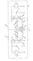
- FIG. 1 1 shows a circuit diagram of a bidirectional resonant converter 100 for transmitting electrical energy between a primary side 110 and a secondary side 120 of the converter 100.
- a first electrical potential V1 is connected via a buffer capacitor C2 to a first switching network 250, wherein the first switching network 250 is designed as a half-bridge circuit and consists of two self-blocking N-channel MOSFETs M1, M2 connected together in their source-drain path.
- the gates of the respective MOSFETs driving control circuit not shown.
- a series resonant circuit formed by a capacitor C1 and an inductance L2 branches which connects a primary inductance L1 of a transformer 150 to the first switching network 250 and, together with the primary inductance L1 of the transformer 150, a primary resonant network 200, in the described embodiment, an LLC primary resonant network forms.
- the secondary inductance L3 is followed by another series resonant circuit formed by the inductor L4 and capacitor C3, whereby the combination of the series resonant circuit formed by the capacitor C3 and the inductor L4 and the secondary inductance L3 of the transformer 150 forms a secondary resonant network 300, which is formed in the illustrated first embodiment of the invention as an LLC resonance network.
- this secondary resonance network 300 is followed by a second switching network 350 formed from two MOSFETs M3, M4, which is connected to a second electrical potential V2 via a buffer capacitor C4.
- illustrated resonant converter 100 functions as a bidirectional converter 100.
- the coupling of the primary resonant network 200 to the secondary resonant network 300 through the transformer 150 is also ensured that by appropriate choice of easily replaceable components capacitor C1 or inductance L2 of the primary resonant network 200 on the primary side 110 and capacitor C3 and inductance L4 of the secondary resonant network 300 on the secondary side 120 by selecting the appropriate matching condition, d. H. by tuning the resonant circuits an optimal for the application transformer 150 can be used without the coupling constant of the transformer 150 would have to be manipulated.
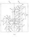
- the second switching network 350 is designed as a multi-stage controlled half-bridge circuit, each of the stages of the second switching network 350 is buffered by means of its own buffer capacitor C4, C8, C10, C12.
- the maximum amount of the second electrical potential V2 is no longer limited to the blocking voltages of the respectively used MOSFETs.
- the transformer 150 is in accordance with the in FIG. 2 illustrated second embodiment equipped with two secondary inductors L3, L5, which are wound on the same transformer core.
- the maximum amount of the second electrical potential V2 is limited only by the insulating capability of the transformer 150.
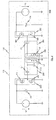
- the converter 100 according to the third embodiment as shown in FIG. 3 is similar to the converter in the first embodiment according to FIG. 1 built up. In contrast to this, however, the converter in each case has a primary resonant network 200 and a secondary resonant network 300, which are now formed only from a respective capacitor C1, C3 and the primary inductance L1 or the secondary inductance L3 of the transformer 150. In this way, it is possible to further influence the resonance curve of the converter 100 by suitable choice of the capacitors C1, C3, but at the same time to expensive additional inductances (in the embodiment according to FIG. 1 the inductors L2, L4) to dispense. At the same time, however, the particular safety of the illustrated transducer 100 also remains in the illustrated third embodiment FIG. 3 maintained, ie in case of failure, ie in case of failure of one of the MOSFETs M1, M2, M3, M4, an immediate decoupling of the respective opposite side of the power flow and in particular of the current flow is further ensured.
- FIG. 4 illustrated fourth embodiment now differs from the third embodiment according to FIG. 3 in that a parallel oscillating capacitor C13 connected in parallel with the primary inductance L1 of the transformer 150 is used. Equally well, alternatively or additionally, a corresponding parallel-resonant capacitor could also be used on the secondary side.
Abstract
Description
Die vorliegende Erfindung betrifft einen Wandler zum Übertragen von elektrischer Leistung zwischen einer Primär- und einer Sekundärseite eines Transformators.The present invention relates to a converter for transmitting electrical power between a primary and a secondary side of a transformer.
Wandler zum Übertragen elektrischer Energie zwischen einer Primär- und einer Sekundärseite eines Transformators sind allgemein aus der Technik bekannt. Insbesondere bei Photovoltaikanlagen kommen vielfach Wandler mit einem Transformator zum Einsatz, deren Primär- und Sekundärseiten jeweils mittels eines Schaltnetzwerkes, insbesondere eines in Halbbrücken- oder Vallbrückenschaltung ausgebildeten Transistornetzwerkes, angesteuert werden. Insbesondere sind derartige herkömmliche Wandlerschaltungen in der Regel dazu ausgelegt, eine primärseitige Gleichspannung in eine sekundärseitige Gleichspannung anderen Betrages zu wandeln. Die primärseitige Brückenschaltung steuert hierzu die Primärwindung des Transformators entsprechend an, um eine Beaufschlagung der Primärwindung mit einer Wechselspannung nachzubilden. Demgemäß dient die sekundärseitige Brückenschaltung dazu, die an der Sekundärwindung des Transformators abgegriffene transformierte Wechselspannung anschließend wieder gleichzurichten.Transducers for transmitting electrical energy between a primary and a secondary side of a transformer are generally known in the art. Particularly in the case of photovoltaic systems, converters with a transformer are frequently used whose primary and secondary sides are each driven by means of a switching network, in particular a transistor network formed in a half-bridge or vias bridge circuit. In particular, such conventional converter circuits are usually designed to convert a primary-side DC voltage into a secondary-side DC voltage of different magnitude. For this purpose, the primary-side bridge circuit controls the primary winding of the transformer accordingly, in order to simulate an application of an alternating voltage to the primary winding. Accordingly, the secondary-side bridge circuit serves to subsequently rectify the transformed alternating voltage picked off at the secondary winding of the transformer.
Derartige Wandler weisen insbesondere den Nachteil auf, dass beim Ausfall einzelner Transistoren in den jeweiligen Brückenschaltungen ungewollt Energie auf die jeweils gegenüberliegende Seite übertragen wird. Eine derartige unerwünschte Energieübertragung hat den Defekt des dem ausgefallenen Transistors jeweils gegenüberliegenden Transistors zur Folge, sodass auf der Primärwie auch auf der Sekundärseite ein unerwünschter Kurzschlussstrom durch den Transformator fließt.In particular, such converters have the disadvantage that if individual transistors in the respective bridge circuits fail, energy is unintentionally transmitted to the respective opposite side. Such an undesired energy transfer results in the defect of the transistor which is in each case opposite the failed transistor, so that an undesired short-circuit current flows through the transformer on the primary as well as on the secondary side.
Es ist daher die Aufgabe der vorliegenden Erfindung, einen Wandler mit einem eine Primär- und eine Sekundärseite verbindenden Transformator anzugeben, welcher mit geringen Verlusten arbeitet und bei dem die Folgen von Bauelementausfällen begrenzt sind.It is therefore the object of the present invention to provide a converter with a transformer connecting a primary and a secondary side, which works with low losses and in which the consequences of component failures are limited.
Die Erfindung geht von der Überlegung aus, bei Minimierung der Magnetfeldverluste gleichzeitig in einem Fehlerfall der Ansteuerschaltungen des Wandlers zu gewährleisten, dass höchstens ein vernachlässigbar kleiner Energiebetrag auf die jeweils andere Transformatorseite übertragen werden kann, welcher keine schädigenden Einflüsse auf die an diese gegenüberliegende Seite angeschalteten Komponenten hat.The invention is based on the consideration, while minimizing the magnetic field losses at the same time in an error case of the drive circuits of the converter to ensure that at most a negligible amount of energy can be transferred to the other side of the transformer, which has no harmful effects on the opposite side of these components Has.
Die Aufgabe wird dadurch gelöst, dass ein auch bidirektional betreibbarer resonanter Wandler mit einer Primär- und einer Sekundärseite sowie einem die Primär- und die Sekundärseite verbindenden und eine Primärinduktivität und mindestens eine Sekundärinduktivität aufweisenden Transformator zum induktiven Verbinden der Primär- und der Sekundärseite angegeben wird, wobei der bidirektionale resonante Wandler weiterhin ein primärseitiges mit der Primärinduktivität des Transformators verbundenes oder die Primärinduktivität resonant einbeziehendes Primärresonanznetzwerk sowie mindestens ein sekundärseitiges mit der mindestens einen Sekundärinduktivität verbundenes oder die Sekundärinduktivität resonant einbeziehendes Sekundärresonanznetzwerk aufweist. Weiterhin weist der Wandler ein primärseitiges erstes Schaltnetzwerk zum ansteuerbar getakteten Durchschalten mindestens eines ersten elektrischen Potentials an das Primärresonanznetzwerks und ein sekundärseitiges zweites Schaltnetzwerk zum ansteuerbar getakteten Durchschalten mindestens eines zweiten elektrischen Potentials an das Sekundärresonanznetzwerk auf. Die erfindungsgemäße Lösung weist eine Reihe wesentlicher Vorteile gegenüber den vorstehend erläuterten herkömmlichen Wandlern auf. Dadurch, dass sowohl primärseitig als auch sekundärseitig jeweils an den Transformatorinduktivitäten Resonanznetzwerke vorgesehen sind, ist insbesondere im Fehlerfall, d. h. beim Ausfall einzelner Bestandteile des primärseitigen ersten Schaltnetzwerkes bzw. des sekundärseitigen zweiten Schaltnetzwerkes eine sofortige Abkopplung der Transformatorinduktivitäten vom Energiefluss gewährleistet. Hierdurch wird einerseits eine unerwünschte und möglicherweise in ihrer Amplitude schädigende Energieübertragung auf die jeweils gegenüberliegende Seite wirksam verhindert. Andererseits ist somit auch gewährleistet, dass beispielsweise im Falle eines ständig durchschaltenden Transistors innerhalb des primärseitigen ersten Schaltnetzwerkes bzw. des sekundärseitigen zweiten Schaltnetzwerkes kein unerwünschter Kurzschlussstrom durch den Transformator fließt.The object is achieved by providing a bidirectionally operable resonant converter having a primary and a secondary side and a transformer connecting the primary and the secondary side and having a primary inductance and at least one secondary inductance for inductively connecting the primary and the secondary side, wherein the bidirectional resonant converter further comprises a primary side connected to the primary inductance of the transformer or the primary inductance resonantly involving primary resonant network and at least one secondary side connected to the at least one secondary inductance or the secondary inductance resonantly involving secondary resonant network. Furthermore, the converter has a primary-side first switching network for controllably clocked switching through at least a first electrical potential to the Primärresonanznetzwerks and a secondary-side second switching network for controllably clocked switching at least a second electrical potential to the secondary resonant network. The solution according to the invention has a number of significant advantages over the conventional converters explained above. Due to the fact that resonant networks are provided both on the primary side and on the secondary side respectively at the transformer inductances, an immediate decoupling of the transformer inductances from the energy flow is ensured in particular in the event of a fault, ie if individual components of the primary-side first switching network or the secondary-side second switching network fail. As a result, on the one hand an undesirable and potentially damaging in terms of amplitude energy transfer to the respective opposite side is effectively prevented. On the other hand, it is therefore also ensured that, for example, in the case of a transistor which is constantly conducting through, no unwanted short-circuit current flows through the transformer within the primary-side first switching network or the secondary-side second switching network.
Durch die jeweils auf beiden Seiten des Transformators vorgesehenen Resonanznetzwerke kann insbesondere das Regelverhalten eines ggfs. zusätzlich vorgesehenen Spannungs- bzw. Leistungsreglers verbessert werden, da das bestmögliche Übertragungsverhalten des Transformators durch einen mittels passender Bemaßung der Resonanznetzwerke gut annäherbaren Resonanzfall gewährleistet ist. Insbesondere ergibt sich im Anpassungsfall des Primärresonanznetzwerkes und des Sekundärresonanznetzwerkes eine schärfer begrenzte Resonanzkurze, deren Steilheit in weitem Maße einstellbar ist. Als hieraus resultierender Effekt kann insbesondere die Trägheit des Regelverhaltens eines ggfs. vorgesehenen und oben beschriebenen Reglers fast beliebig eingestellt werden.In particular, the control behavior of a possibly additionally provided voltage or power controller can be improved by the respective resonant networks provided on both sides of the transformer, since the best possible transmission behavior of the transformer is ensured by a resonance case that can be approached well by means of suitable dimensioning of the resonant networks. In particular, in the case of adaptation of the primary resonant network and the secondary resonant network results in a sharply defined resonance curves whose steepness is largely adjustable. As a result of this effect, in particular the inertia of the control behavior of a possibly provided and above-described regulator can be set almost arbitrarily.
Insbesondere ist durch die erfindungsgemäße Lösung, d. h. durch das Vorsehen sowohl eines Primärresonanznetzwerkes als auch eines Sekundärresonanznetzwerkes durch gezielte Beeinflussung des Resonanzverhaltens bei entsprechender Abstimmung der Resonanzkreise, eine bevorzugte Übertragungsfrequenz, beispielsweise 20 kHz, wählbar, ohne Einfluss auf die Kopplungskonstante des Transformators nehmen zu müssen. Hierdurch ist es insbesondere möglich, einen möglichst optimalen Transformator verwenden zu können, ohne in aufwendiger Weise die Kopplungskonstante des Transformators manipulieren zu müssen.In particular, by the inventive solution, ie by the provision of both a primary resonant network and a secondary resonant network by selectively influencing the resonance behavior with appropriate tuning of the resonant circuits, a preferred transmission frequency, for example, 20 kHz, selectable, without having to influence the coupling constant of the transformer. This makes it possible in particular to be able to use the best possible transformer, without having to manipulate the coupling constant of the transformer in a complex manner.
Durch den strukturell weitgehend symmetrischen Aufbau des erfindungsgemäßen Wandlers ist es zudem leicht möglich, den resonanten Wandler bidirektional zu betreiben. So ist es in unaufwendiger Weise möglich, sowohl Energie von der Primär- auf die Sekundärseite zu übertragen, als auch umgekehrt. Zudem ist es in besonders einfacher Weise möglich, beliebige Wandlungen zwischen Gleich- und Wechselgrößen vorzunehmen, d. h. insbesondere den erfindungsgemäßen bidirektionalen resonanten Wandler wahlweise als DC-/AC-Wandler oder als AC-/DC-Wandler flexibel einzusetzen.Due to the structurally largely symmetrical design of the converter according to the invention, it is also easily possible to operate the resonant converter bidirectionally. Thus, it is possible in an uncomplicated manner to transfer energy from the primary to the secondary side as well as vice versa. In addition, it is possible in a particularly simple manner to make any conversions between DC and AC variables, d. H. In particular, the bidirectional resonant converter according to the invention can optionally be used flexibly as a DC / AC converter or as an AC / DC converter.
Vorteilhafte Weiterbildungen der Erfindung sind in den Unteransprüchen angegeben.Advantageous developments of the invention are specified in the subclaims.
So ist es beispielsweise vorgesehen, dass das Primärresonanznetzwerk die Primärinduktivität des Transformators einbezieht und somit einen ersten Reihenschwingkreis bildet. Hierdurch ist ein besonders kostengünstiger Aufbau möglich, da im Idealfall ein vergleichsweise kostengünstiger Kondensator eingesetzt werden kann, welcher dann das erforderliche vorteilhafte Resonanzverhalten, d. h. die Ausbildung eines Reihenschwingkreises, durch direkten resonanten Energieaustausch mit der Primärinduktivität des Transformators vornimmt. Gleichzeitig bleibt die sofortige energetische Abkopplung im Fehlerfall gewährleistet.For example, it is provided that the primary resonant network includes the primary inductance of the transformer and thus forms a first series resonant circuit. As a result, a particularly cost-effective design is possible, since in the ideal case, a comparatively inexpensive capacitor can be used, which then the required advantageous resonance behavior, d. H. the formation of a series resonant circuit, by direct resonant energy exchange with the primary inductance of the transformer makes. At the same time, the immediate energy decoupling in the event of a fault remains guaranteed.
Alternativ oder zusätzlich ist vorgesehen, dass das sekundäre Resonanznetzwerk einen die mindestens eine Sekundärinduktivität des Transformators einbeziehenden zweiten Reihenschwingkreis bildet. Insbesondere dann, wenn sowohl auf Seiten des primären Resonanznetzwerkes als auch auf Seiten des sekundären Resonanznetzwerkes lediglich ein zusätzlicher Kondensator eingesetzt wird, können die Kosten zur Verwirklichung des erfindungsgemäßen bidirektionalen resonanten Wandlers weiter reduziert werden.Alternatively or additionally, it is provided that the secondary resonant network forms a second series resonant circuit incorporating the at least one secondary inductance of the transformer. In particular, if only one additional capacitor is used both on the side of the primary resonant network and on the side of the secondary resonant network, the costs for realizing the bidirectional resonant converter according to the invention can be further reduced.
In einer weiteren Ausführung ist vorgesehen, dass der erste und/oder der zweite Reihenschwingkreis unter Einbezug der jeweiligen Transformatorinduktivität einen LC-Reihenschwingkreis bilden.In a further embodiment, it is provided that the first and / or the second series resonant circuit form an LC series resonant circuit, taking into account the respective transformer inductance.
Alternativ kann es aber auch vorgesehen sein, dass das Primärresonanznetzwerk und/oder das sekundäre Resonanznetzwerk jeweils einen LLC-Reihenschwingkreis bilden. In beiden Fällen ist es möglich, dass die jeweiligen Reihenschwingkreise unter Einbeziehung oder auch ohne Einbezug der jeweiligen Transformatorinduktivitäten ausgebildet sind. In jedem Fall wird durch eine derartige Lösung erreicht, dass die maximale Spannungsänderung des Wandlers durch die Eingangsspannung, d. h. die auf der Primär- oder der Sekundärseite jeweils anliegenden Spannung und durch das Bindungsverhältnis des Transformators, begrenzt ist. Auch bei hoher zu wandelnden Spannung ist somit eine hohe Effizienz gewährleistet, wobei der Wandler weiterhin bidirektional betreibbar ist.Alternatively, however, it may also be provided that the primary resonance network and / or the secondary resonance network each form an LLC series resonant circuit. In both cases it is possible that the respective Series resonant circuits are formed with inclusion or without inclusion of the respective Transformatoreninduktivitäten. In any case, it is achieved by such a solution that the maximum voltage change of the converter by the input voltage, ie, the voltage applied to the primary or the secondary side voltage and by the binding ratio of the transformer is limited. Even with high voltage to be converted thus high efficiency is ensured, the converter is still bidirectionally operable.
Insbesondere dann, wenn der Wandler als Wechselrichter arbeitet, ist aufgrund der resonanten Ausführung gewährleistet, dass der Wandler auch mit relativ kostengünstigen elektronischen Schaltern wie beispielsweise MOSFETs hochfrequent geschaltet werden kann, wodurch die zum Einsatz kommenden Induktivitäten relativ klein sein können und somit ihrerseits zu einer gesteigerten Kosteneffizienz des erfindungsgemäßen Wandlers beitragen.In particular, when the converter operates as an inverter, it is ensured due to the resonant design that the converter can be switched to high frequency even with relatively inexpensive electronic switches such as MOSFETs, whereby the inductors used for use can be relatively small and thus in turn to an increased Contribute cost efficiency of the converter according to the invention.
Gleichzeitig ist durch die beidseitige Ausführung mit Resonanzkreisen, insbesondere mit LLC-Reihenschwingkreisen gewährleistet, dass die übertragbare Leistung und hierbei vor allem der übertragbare Strom allein durch passive Schaltungskomponenten wirksam begrenzt ist, sodass es nicht zur unerwünschten erhöhten Energieübertragung im Fehlerfall kommt.At the same time is ensured by the two-sided design with resonant circuits, in particular with LLC series resonant circuits that the transmittable power and in this case especially the transmittable power is effectively limited solely by passive circuit components, so it does not come to unwanted increased energy transfer in case of failure.
In einer weiteren Ausführung weist der Wandler auf der Primärseite und/oder auf der Sekundärseite jeweils einen zusätzlichen und zu der jeweiligen Transformatorinduktivität parallel geschalteten Parallelschwingkondensator auf. Hierdurch ist die Resonanzkurve des resonanten bidirektionalen Wandlers noch gezielter und feiner beeinflussbar.In a further embodiment, the converter on the primary side and / or on the secondary side in each case has an additional and parallel to the respective transformer inductance parallel resonant capacitor. As a result, the resonance curve of the resonant bidirectional transducer is even more targeted and finely influenced.
In weiteren Ausführungen sind das primärseitige Schaltnetzwerk, das sekundärseitige Schaltnetzwerk oder auch beide Schaltnetzwerke als Transistornetzwerke in Halbbrückenschaltung ausgebildet. Hierbei können insbesondere preiswerte Standard-Feldeffekttransistoren zum Einsatz kommen, da durch die beidseitig resonante Ansteuerung der Transformatorinduktivitäten auch mit derartigen Standardbauteilen eine hochfrequente Ansteuerung gewährleistet werden kann. Durch den Einsatz von Halbbrückenschaltungen ist zudem ein vergleichweise kostengünstiger Aufbau möglich.In further embodiments, the primary-side switching network, the secondary-side switching network or both switching networks are designed as transistor networks in half-bridge circuit. In this case, in particular inexpensive standard field-effect transistors can be used, since a high-frequency control can be ensured by the double-sided resonant control of the transformer inductances even with such standard components. By using half-bridge circuits, a comparatively inexpensive construction is also possible.
In einer weiteren Ausführung ist vorgesehen, das primärseitige erste Schaltnetzwerk, das sekundärseitige zweite Schaltnetzwerk oder auch beide Schaltnetzwerke jeweils als Transistornetzwerke in Vollbrückenschaltung auszubilden. Durch den Einsatz von Vollbrückenschaltungen kann insbesondere die jeweils ausgangsseitige Wellenform der abzugebenden Spannung gezielter beeinflusst werden, was in bestimmten Anwendungsfällen von Vorteil sein kann.In a further embodiment, it is provided to design the primary-side first switching network, the secondary-side second switching network or even both switching networks in each case as transistor networks in full-bridge connection. Through the use of full bridge circuits, in particular the respective output-side waveform of the voltage to be delivered can be more selectively influenced, which may be advantageous in certain applications.
In einer noch weiteren Ausführung sind das primärseitige erste Schaltnetzwerk, das sekundärseitige zweite Schaltnetzwerk oder auch beide Schaltnetzwerke jeweils mehrstufig aufgebaut. Ein mehrstufiger Aufbau ist insbesondere dann leicht möglich, wenn die jeweilige Transformatorwindung, beispielsweise die Sekundärwindung, geteilt wird, jedoch weiterhin auf den gleichen Transformatorkern gewickelt wird. Hierdurch ist es möglich, die jeweilige derartig aufgebaute Seite dahingehend auszulegen, dass sie auch eine Spannung liefern kann, welche über der Sperrspannung der jeweils eingesetzten Transistoren liegt. Insbesondere dann, wenn preisgünstige Feldeffekttransistoren wie MOSFETs eingesetzt werden, ist es möglich, derartige MOSFETs in einer Source-Drain-Kaskade zusammenzuschalten, d. h. ihre jeweiligen Source-Drain-Strecken in Reihe zu schalten. Dies hat den Vorteil, dass die erreichbare Spannung lediglich durch die Isolationsfähigkeit des Transformators begrenzt ist, welche in bestimmten Anwendungsfällen höher liegen kann als die Sperrspannung der eingesetzten Schaltelemente, wie beispielsweise MOSFETS.In yet another embodiment, the primary-side first switching network, the secondary-side second switching network or both switching networks are each constructed in multiple stages. A multi-stage construction is particularly easily possible if the respective transformer winding, for example the secondary winding, is divided, but continues to be wound onto the same transformer core. This makes it possible to design the respective side constructed in such a way that it can also deliver a voltage which lies above the blocking voltage of the transistors used in each case. In particular, when inexpensive field effect transistors such as MOSFETs are used, it is possible to interconnect such MOSFETs in a source-drain cascade, i. H. to connect their respective source-drain paths in series. This has the advantage that the achievable voltage is limited only by the insulating capability of the transformer, which may be higher in certain applications than the blocking voltage of the switching elements used, such as MOSFETS.
In einer weiteren Ausführung sind das primärseitige erste Schaltnetzwerk, das sekundärseitige zweite Schaltnetzwerk oder auch beide Schaltnetzwerke jeweils mit bidirektionalen elektronischen Schaltern ausgestattet. Hierfür kommen insbesondere gegenläufig geschaltete Feldeffekttransistoren oder auch gegenläufig geschaltete IGB-Transistoren in Frage. In diesem Fall ist es einfach möglich, den bidirektionalen resonanten Wandler sowohl als DC-/AC-Wandler als auch AC-/DC-Wandler zu verwenden. Grundsätzlich sind im Rahmen der Erfindung aber auch andere elektronische Schalter, etwa Thyristoren, einsetzbar.In a further embodiment, the primary-side first switching network, the secondary-side second switching network or both switching networks are each equipped with bidirectional electronic switches. For this purpose, in particular counter-field effect transistors or counter-switched IGB transistors come into question. In this case, it is easily possible to use the bidirectional resonant converter as both a DC / AC converter and an AC / DC converter. In principle, however, other electronic switches, such as thyristors, can be used within the scope of the invention.
Neben einer einphasigen Ausführung des Wandlers ist es möglich, den Wandler für mehrphasige Wechselspannungen, also primär- und/oder sekundärseitig für mehrphasige Wechselspannungen, insbesondere für eine dreiphasige Wechselspannung auszulegen. Dies hat den Vorteil, dass ein derartig aufgebauter Wandler beispielsweise auch in Mehrphasen-Wechselspannungsnetzen ("Drehstromnetzen") zum Einsatz kommen kann.In addition to a single-phase version of the converter, it is possible to design the converter for multiphase AC voltages, ie primary and / or secondary side for multiphase AC voltages, in particular for a three-phase AC voltage. This has the advantage that such a structure Transducer, for example, in multi-phase AC networks ("three-phase networks") can be used.
In einer weiteren Ausführung ist der Wandler ferner mit einem Regler ausgestattet, wobei der Regler ausgelegt ist, die Amplitude des ersten oder des zweiten Potentials durch geeignetes Ansteuern des jeweiligen anderen Schaltnetzwerkes zu regeln. Hierdurch ist durch die Kombination mit den auf beiden Seiten vorgesehenen Resonanznetzwerken ein besonders gutes Spannungsfolgeverhalten erzielbar. Hierbei kann der Regler zum geeigneten Ansteuern des jeweils anderen Schaltnetzwerkes durch eine Beeinflussung der Frequenz, der Pulsweite, der Pulsdichte oder/oder der Pulsfolge eines Ansteuertaktsignals ausgelegt sein.In a further embodiment, the converter is further equipped with a controller, wherein the controller is designed to regulate the amplitude of the first or the second potential by suitably driving the respective other switching network. As a result, a particularly good voltage sequence behavior can be achieved by combining with the resonant networks provided on both sides. In this case, the controller may be designed to suitably control the respective other switching network by influencing the frequency, the pulse width, the pulse density or / or the pulse sequence of a drive clock signal.
In diesem Zusammenhang kann es auch vorgesehen sein, dass bei einem Transformator, weicher mindestens zwei Sekundärinduktivitäten aufweist, das primärseitige erste Schaltnetzwerk dahingehend ausgelegt ist, durch Beeinflussung der Frequenz des Ansteuertaktsignals zusätzlich eine Leistungsregelung vorzunehmen. In diesem Fall wird die jeweils sekundäre Seite durch bidirektionale Schalter aktiv angesteuert, was für die beschriebene Spannungsregelung, d. h. Spannungsamplitudenregelung sorgt. Auf der Primärseite wird die Kontrolle der abgegebenen Leistung durch die beschriebene Frequenzregelung erreicht, wodurch sich ein mehrphasiger DC-/AC-Wandler ergibt.In this context, it may also be provided that, in the case of a transformer having at least two secondary inductances, the primary-side first switching network is designed to additionally effect a power control by influencing the frequency of the drive clock signal. In this case, the respective secondary side is actively driven by bidirectional switches, which is the case for the described voltage regulation, ie. H. Voltage amplitude control ensures. On the primary side, the control of the power output is achieved by the described frequency control, resulting in a multi-phase DC / AC converter.
Ein beschriebener erfindungsgemäßer bidirektionaler resonanter Wandler kann vorzugsweise in einem Wechselrichter zum Einsatz kommen.A described inventive bidirectional resonant converter may preferably be used in an inverter.
Im Folgenden werden vier bevorzugte Ausführungsbeispiele des erfindungsgemäßen bidirektionalen resonanten Wandlers anhand einer Zeichnung näher erläutert. Es zeigen:
-
Fig. 1 ein Schaltbild eines bidirektionalen resonanten Wandlers gemäß einer ersten Ausführungsform der Erfindung; -
Fig. 2 ein Schaltbild eines erfindungsgemäßen bidirektionalen resonanten Wandlers gemäß einer zweiten Ausführungsform der Erfindung; -
Fig. 3 ein Schaltbild des erfindungsgemäßen bidirektionalen resonanten Wandlers gemäß einer dritten Ausführungsform der Erfindung; und -
Fig. 4 ein Schaltbild des erfindungsgemäßen bidirektionalen resonanten Wandlers gemäß einer vierten Ausführungsform der Erfindung.
-
Fig. 1 a circuit diagram of a bidirectional resonant converter according to a first embodiment of the invention; -
Fig. 2 a circuit diagram of a bidirectional resonant converter according to the invention according to a second embodiment of the invention; -
Fig. 3 a circuit diagram of the bidirectional resonant converter according to the invention according to a third embodiment of the invention; and -
Fig. 4 a circuit diagram of the bidirectional resonant converter according to the invention according to a fourth embodiment of the invention.
Durch die Transformatorkopplung wird elektrische Energie auf die Sekundärwindung L3 des Transformators 150 übertragen, welche bereits Teil der Sekundärseite 120 ist. In symmetrischen Aufbau zur Primärseite 110 schließt an die Sekundärinduktivität L3 ein weiterer aus Induktivität L4 und Kondensator C3 gebildeter Reihenschwingkreis an, womit die Kombination aus dem aus dem Kondensator C3 und der Induktivität L4 gebildeten Reihenschwingkreis und der Sekundärinduktivität L3 des Transformators 150 ein Sekundärresonanznetzwerk 300 bildet, das im gezeigten ersten Ausführungsbeispiel der Erfindung als LLC-Resonanznetzwerk ausgebildet ist.Due to the transformer coupling, electrical energy is transferred to the secondary winding L3 of the
In analoger Weise zur Beschreibung des ersten Schaltnetzwerkes 250 auf der Primärseite 110 schließt sich an dieses sekundäre Resonanznetzwerk 300 ein aus zwei MOSFETs M3, M4 gebildetes zweites Schaltnetzwerk 350 an, welches über einen Pufferkondensator C4 an ein zweites elektrisches Potential V2 angebunden ist.In an analogous manner to the description of the
Insbesondere durch den symmetrischen Aufbau kommt eine Spannungsübertragung und eine Spannungswandlung, d. h. eine sowohl in Amplitude als auch in ihrer Art beeinflussbare Spannungswandlung sowohl vom ersten elektrischen Potential V1 auf das zweite elektrische Potential V2 als auch in umgekehrter Richtung, in Frage. Der in
Durch die resonante Ausbildung, d. h. die Ankopplung des Primärresonanznetzwerkes 200 an das sekundäre Resonanznetzwerk 300 durch den Transformator 150, ist zudem gewährleistet, dass durch entsprechende Wahl der einfach austauschbaren Komponenten Kondensator C1 bzw. Induktivität L2 des Primärresonanznetzwerkes 200 auf der Primärseite 110 bzw. Kondensator C3 und Induktivität L4 des sekundären Resonanznetzwerkes 300 auf der Sekundärseite 120 durch Wahl der entsprechenden Anpassbedingung, d. h. durch Abstimmung der Resonanzkreise ein für den Einsatzzweck optimaler Transformator 150 zum Einsatz kommen kann, ohne dass die Kopplungskonstante des Transformators 150 manipuliert werden müsste.Due to the resonant training, d. H. the coupling of the primary
Wie aus dem zweiten Ausführungsbeispiel gemäß
Der Wandler 100 gemäß dem dritten Ausführungsbeispiel, wie in
Das in
Hierdurch ist es möglich, die Resonanzkurve des erfindungsgemäßen bidirektionalen resonanten Wandlers 100 noch feiner zu beeinflussen.This makes it possible to influence the resonance curve of the bidirectional
Die Ausführung der Erfindung ist nicht auf die oben beschriebenen Beispiele und hervorgehobenen Aspekte beschränkt, sondern ebenso in einer Vielzahl von Abwandlungen möglich, die im Rahmen fachgemäßen Handelns liegen.The embodiment of the invention is not limited to the examples and highlighted aspects described above, but also possible in a variety of modifications, which are within the scope of technical action.
Claims (15)
Applications Claiming Priority (1)
| Application Number | Priority Date | Filing Date | Title |
|---|---|---|---|
| DE102011119355A DE102011119355A1 (en) | 2011-11-23 | 2011-11-23 | Bidirectional resonant converter |
Publications (1)
| Publication Number | Publication Date |
|---|---|
| EP2597766A2 true EP2597766A2 (en) | 2013-05-29 |
Family
ID=47221160
Family Applications (1)
| Application Number | Title | Priority Date | Filing Date |
|---|---|---|---|
| EP12192517.6A Withdrawn EP2597766A2 (en) | 2011-11-23 | 2012-11-14 | Bidirectional resonant converter |
Country Status (2)
| Country | Link |
|---|---|
| EP (1) | EP2597766A2 (en) |
| DE (1) | DE102011119355A1 (en) |
Cited By (5)
| Publication number | Priority date | Publication date | Assignee | Title |
|---|---|---|---|---|
| CN104184323A (en) * | 2014-01-14 | 2014-12-03 | 深圳市中兴昆腾有限公司 | Bidirectional DC/DC converter circuit |
| EP2996237A1 (en) * | 2014-09-15 | 2016-03-16 | Alstom Technology Ltd | Resonant bidirectional DC/DC converter |
| CN109149942A (en) * | 2018-08-06 | 2019-01-04 | 西安理工大学 | A kind of multi-frequency section control method for harmonic high frequency vibration shape commutator transformer |
| US10581334B2 (en) | 2017-02-04 | 2020-03-03 | Abb Schweiz Ag | DC-DC converter and control method |
| EP3713066A1 (en) * | 2019-03-21 | 2020-09-23 | Siemens Aktiengesellschaft | Dc converter having a secondary oscillation circuit capacitor and method for operating a dc converter |
-
2011
- 2011-11-23 DE DE102011119355A patent/DE102011119355A1/en not_active Withdrawn
-
2012
- 2012-11-14 EP EP12192517.6A patent/EP2597766A2/en not_active Withdrawn
Non-Patent Citations (1)
| Title |
|---|
| None |
Cited By (7)
| Publication number | Priority date | Publication date | Assignee | Title |
|---|---|---|---|---|
| CN104184323A (en) * | 2014-01-14 | 2014-12-03 | 深圳市中兴昆腾有限公司 | Bidirectional DC/DC converter circuit |
| EP2996237A1 (en) * | 2014-09-15 | 2016-03-16 | Alstom Technology Ltd | Resonant bidirectional DC/DC converter |
| US10581334B2 (en) | 2017-02-04 | 2020-03-03 | Abb Schweiz Ag | DC-DC converter and control method |
| CN109149942A (en) * | 2018-08-06 | 2019-01-04 | 西安理工大学 | A kind of multi-frequency section control method for harmonic high frequency vibration shape commutator transformer |
| CN109149942B (en) * | 2018-08-06 | 2020-10-27 | 西安理工大学 | Multi-frequency-band control method for high-frequency resonant DC transformer |
| EP3713066A1 (en) * | 2019-03-21 | 2020-09-23 | Siemens Aktiengesellschaft | Dc converter having a secondary oscillation circuit capacitor and method for operating a dc converter |
| WO2020187513A1 (en) | 2019-03-21 | 2020-09-24 | Siemens Aktiengesellschaft | Dc-to-dc converter having a secondary resonant circuit capacitor, and method for operating a dc-to-dc converter |
Also Published As
| Publication number | Publication date |
|---|---|
| DE102011119355A1 (en) | 2013-05-23 |
Similar Documents
| Publication | Publication Date | Title |
|---|---|---|
| DE4234725B4 (en) | DC converter | |
| EP2073366B1 (en) | dc-dc converter with resonant converter | |
| EP1157320B1 (en) | Method for generating a regulated direct voltage from an alternating voltage and power supply device for implementing said | |
| DE10122534A1 (en) | Resonant converter | |
| DE102011051482A1 (en) | Bridge circuit arrangement and method of operation for a voltage converter and voltage converter | |
| DE202007005779U1 (en) | MF plasma power generator for plasma process, has decoupling circuit for decoupling switching element by potential of output network, and has DC current supply connecting to inverter | |
| EP2597766A2 (en) | Bidirectional resonant converter | |
| EP2180586B1 (en) | Converter circuit and unit and system with such a converter circuit | |
| EP2709257A2 (en) | Power converter circuit and method for controlling the power converter circuit | |
| DE102010060508B4 (en) | Voltage converter with a storage choke with a winding and a storage choke with two windings | |
| EP3332481B1 (en) | Asymmetrical bipolar voltage supply | |
| EP3713066A1 (en) | Dc converter having a secondary oscillation circuit capacitor and method for operating a dc converter | |
| EP1363474A2 (en) | Inductive heating device of workpieces | |
| EP2262088A1 (en) | DC-DC converter | |
| EP1276218A2 (en) | Electric circuit device | |
| DE102005001322A1 (en) | Method and circuit for galvanically isolated transmission of a signal | |
| DE2819676A1 (en) | DC voltage converter for power supply - has at least two half-bridge converters using transformer primary winding sections separated by transistors | |
| DE10128687A1 (en) | DC converter | |
| WO2005124985A1 (en) | Matrix converter for coupling three-phase voltage networks | |
| EP3915186A1 (en) | Dc-dc converter with bridge circuit for voltage-free switching, and associated method | |
| EP3949099A1 (en) | Isolated dc/dc converter with secondary-side full bridge diode rectifier and asymmetrical auxiliary capacitor | |
| DE10138751B4 (en) | Inverter with fast-switching controllable electronic switches, in particular IGBT switches, and method for controlling such an inverter | |
| DE102013211010A1 (en) | Circuit arrangement for controlling a T-type three-phase inverter and method for operating such a circuit arrangement | |
| EP2562918A1 (en) | Circuit arrangement with electronic switch | |
| WO2002045249A2 (en) | Circuit arrangement for dc/dc converters with low output voltage |
Legal Events
| Date | Code | Title | Description |
|---|---|---|---|
| PUAI | Public reference made under article 153(3) epc to a published international application that has entered the european phase |
Free format text: ORIGINAL CODE: 0009012 |
|
| 17P | Request for examination filed |
Effective date: 20121114 |
|
| AK | Designated contracting states |
Kind code of ref document: A2 Designated state(s): AL AT BE BG CH CY CZ DE DK EE ES FI FR GB GR HR HU IE IS IT LI LT LU LV MC MK MT NL NO PL PT RO RS SE SI SK SM TR |
|
| AX | Request for extension of the european patent |
Extension state: BA ME |
|
| STAA | Information on the status of an ep patent application or granted ep patent |
Free format text: STATUS: THE APPLICATION IS DEEMED TO BE WITHDRAWN |
|
| 18D | Application deemed to be withdrawn |
Effective date: 20150602 |