EP2572921A1 - Circuit monitoring - Google Patents
Circuit monitoring Download PDFInfo
- Publication number
- EP2572921A1 EP2572921A1 EP11182737A EP11182737A EP2572921A1 EP 2572921 A1 EP2572921 A1 EP 2572921A1 EP 11182737 A EP11182737 A EP 11182737A EP 11182737 A EP11182737 A EP 11182737A EP 2572921 A1 EP2572921 A1 EP 2572921A1
- Authority
- EP
- European Patent Office
- Prior art keywords
- electrical
- battery
- circuit
- power flow
- impedance
- Prior art date
- Legal status (The legal status is an assumption and is not a legal conclusion. Google has not performed a legal analysis and makes no representation as to the accuracy of the status listed.)
- Withdrawn
Links
Images
Classifications
-
- B—PERFORMING OPERATIONS; TRANSPORTING
- B60—VEHICLES IN GENERAL
- B60L—PROPULSION OF ELECTRICALLY-PROPELLED VEHICLES; SUPPLYING ELECTRIC POWER FOR AUXILIARY EQUIPMENT OF ELECTRICALLY-PROPELLED VEHICLES; ELECTRODYNAMIC BRAKE SYSTEMS FOR VEHICLES IN GENERAL; MAGNETIC SUSPENSION OR LEVITATION FOR VEHICLES; MONITORING OPERATING VARIABLES OF ELECTRICALLY-PROPELLED VEHICLES; ELECTRIC SAFETY DEVICES FOR ELECTRICALLY-PROPELLED VEHICLES
- B60L15/00—Methods, circuits, or devices for controlling the traction-motor speed of electrically-propelled vehicles
- B60L15/007—Physical arrangements or structures of drive train converters specially adapted for the propulsion motors of electric vehicles
-
- B—PERFORMING OPERATIONS; TRANSPORTING
- B60—VEHICLES IN GENERAL
- B60L—PROPULSION OF ELECTRICALLY-PROPELLED VEHICLES; SUPPLYING ELECTRIC POWER FOR AUXILIARY EQUIPMENT OF ELECTRICALLY-PROPELLED VEHICLES; ELECTRODYNAMIC BRAKE SYSTEMS FOR VEHICLES IN GENERAL; MAGNETIC SUSPENSION OR LEVITATION FOR VEHICLES; MONITORING OPERATING VARIABLES OF ELECTRICALLY-PROPELLED VEHICLES; ELECTRIC SAFETY DEVICES FOR ELECTRICALLY-PROPELLED VEHICLES
- B60L3/00—Electric devices on electrically-propelled vehicles for safety purposes; Monitoring operating variables, e.g. speed, deceleration or energy consumption
- B60L3/0023—Detecting, eliminating, remedying or compensating for drive train abnormalities, e.g. failures within the drive train
- B60L3/0069—Detecting, eliminating, remedying or compensating for drive train abnormalities, e.g. failures within the drive train relating to the isolation, e.g. ground fault or leak current
-
- B—PERFORMING OPERATIONS; TRANSPORTING
- B60—VEHICLES IN GENERAL
- B60L—PROPULSION OF ELECTRICALLY-PROPELLED VEHICLES; SUPPLYING ELECTRIC POWER FOR AUXILIARY EQUIPMENT OF ELECTRICALLY-PROPELLED VEHICLES; ELECTRODYNAMIC BRAKE SYSTEMS FOR VEHICLES IN GENERAL; MAGNETIC SUSPENSION OR LEVITATION FOR VEHICLES; MONITORING OPERATING VARIABLES OF ELECTRICALLY-PROPELLED VEHICLES; ELECTRIC SAFETY DEVICES FOR ELECTRICALLY-PROPELLED VEHICLES
- B60L50/00—Electric propulsion with power supplied within the vehicle
- B60L50/50—Electric propulsion with power supplied within the vehicle using propulsion power supplied by batteries or fuel cells
- B60L50/51—Electric propulsion with power supplied within the vehicle using propulsion power supplied by batteries or fuel cells characterised by AC-motors
-
- G—PHYSICS
- G01—MEASURING; TESTING
- G01R—MEASURING ELECTRIC VARIABLES; MEASURING MAGNETIC VARIABLES
- G01R31/00—Arrangements for testing electric properties; Arrangements for locating electric faults; Arrangements for electrical testing characterised by what is being tested not provided for elsewhere
- G01R31/005—Testing of electric installations on transport means
- G01R31/006—Testing of electric installations on transport means on road vehicles, e.g. automobiles or trucks
-
- G—PHYSICS
- G01—MEASURING; TESTING
- G01R—MEASURING ELECTRIC VARIABLES; MEASURING MAGNETIC VARIABLES
- G01R31/00—Arrangements for testing electric properties; Arrangements for locating electric faults; Arrangements for electrical testing characterised by what is being tested not provided for elsewhere
- G01R31/50—Testing of electric apparatus, lines, cables or components for short-circuits, continuity, leakage current or incorrect line connections
- G01R31/54—Testing for continuity
-
- Y—GENERAL TAGGING OF NEW TECHNOLOGICAL DEVELOPMENTS; GENERAL TAGGING OF CROSS-SECTIONAL TECHNOLOGIES SPANNING OVER SEVERAL SECTIONS OF THE IPC; TECHNICAL SUBJECTS COVERED BY FORMER USPC CROSS-REFERENCE ART COLLECTIONS [XRACs] AND DIGESTS
- Y02—TECHNOLOGIES OR APPLICATIONS FOR MITIGATION OR ADAPTATION AGAINST CLIMATE CHANGE
- Y02T—CLIMATE CHANGE MITIGATION TECHNOLOGIES RELATED TO TRANSPORTATION
- Y02T10/00—Road transport of goods or passengers
- Y02T10/60—Other road transportation technologies with climate change mitigation effect
- Y02T10/64—Electric machine technologies in electromobility
-
- Y—GENERAL TAGGING OF NEW TECHNOLOGICAL DEVELOPMENTS; GENERAL TAGGING OF CROSS-SECTIONAL TECHNOLOGIES SPANNING OVER SEVERAL SECTIONS OF THE IPC; TECHNICAL SUBJECTS COVERED BY FORMER USPC CROSS-REFERENCE ART COLLECTIONS [XRACs] AND DIGESTS
- Y02—TECHNOLOGIES OR APPLICATIONS FOR MITIGATION OR ADAPTATION AGAINST CLIMATE CHANGE
- Y02T—CLIMATE CHANGE MITIGATION TECHNOLOGIES RELATED TO TRANSPORTATION
- Y02T10/00—Road transport of goods or passengers
- Y02T10/60—Other road transportation technologies with climate change mitigation effect
- Y02T10/70—Energy storage systems for electromobility, e.g. batteries
Definitions
- the invention relates to a method for monitoring a circuit of a battery and an electrical consumer connected to the battery and a device for carrying out the method.
- circuits that are housed in non-stationary, movable devices, such as a vehicle usually electrical consumers are powered by a battery with electrical energy.
- the electrical load and the battery are installed in a circuit.
- the power circuit of the battery and the electrical load can be closed by an unintentional contact, for example by persons via a ground fault.
- life-threatening leakage currents can flow through the touching person in the form of body currents.
- the intermediate circuit such as an intermediate circuit capacitor, is also contained in the power-conducting circuit between the electrical load and the battery, these must be discharged for safety purposes, for example for the purpose of repairing or eliminating errors after interrupting the power-carrying circuit, so that the maintenance personnel are not dangerous when the temporary storage device is touched Body currents are made to flow.
- the power-conducting circuit is made using so-called pilot lines or high-voltage interlocks supervised. This is an electrically redundant circuit, which is connected in parallel with the power-carrying circuit. If the redundant circuit is open, then it can be assumed that the power-conducting circuit is open.
- the invention proposes to find out, based on a variation of the power flow through the circuit of the battery and the electrical load and a reaction of the circuit with the battery and the electrical load, whether the circuit is interrupted.
- the proposal is based on the finding that changes in the power flow must lead to plausible responses in the circuit when the power circuit is closed. In other words, a defined change in the power flow between the battery and the electrical load must lead to a verifiable reaction of the circuit when the circuit between the battery and the electrical load is closed.
- the consideration of the invention is therefore to define a defined change in the power flow and to first determine the verifiable reaction, for example by calculation. Then, according to the invention, it can be checked in the circuit whether the testable reaction actually occurs.
- the invention therefore provides a method of monitoring a circuit having a battery and an electrical consumer connected to the battery.
- the specified method includes varying an electrical power flow between the battery and the electrical load, detecting a response of the circuit to the variation and determining an error if the sensed response deviates from a predetermined response.
- any electrical and physical quantities in the circuit that depend on the power flow between the battery and the electrical load can be used. These may be, for example, the values of the total resistance or the operating point of the circuit. However, other physical quantities, such as heat generation or interference emission, can also be used to monitor the circuit between the battery and the electrical consumer according to the invention.
- interruptions of the circuit between the battery and the electrical load can be determined without an additional redundant circuit, such as a pilot line or a high-voltage interlock is necessary.
- additional redundant circuit such as a pilot line or a high-voltage interlock is necessary.
- the disclosed method may also monitor the circuitry of the circuit with respect to a much wider variety of sources of error, since the response of the circuit to a variation in power flow will deviate from the predetermined response not only in the event of a circuit break, but also in the event of other errors.
- faults can be, for example, shorts in the circuit but also component drift effects, which, for example, can occur at the battery or the electrical load due to age.
- the variation of the electrical power flow takes place with a specific pattern.
- This pattern is for example by means of a signal generator not only easier to produce, the pattern can also be easily adapted to the conditions of the circuit, so that the circuit is not transferred by the variation of the power flow, for example, in critical operating conditions that can damage the circuit or even destroy.
- the specified method comprises the step of detecting an electrical variable describing the circuit and searching for the pattern in the detected electrical quantity.
- the development is based on the idea that in the case of interruptions and short circuits in the circuit between the battery and the electrical load no electrical power can be transmitted. Consequently, a variation of the power flow also leads to no reaction of the circuit.
- the pattern can therefore only be found in the response of the circuit if the circuit is free of open circuits and short circuits. In this way, the verification of whether the measured reaction deviates from the predetermined reaction can be carried out in a particularly simple manner, since the predetermined reaction is already known by the pattern used and does not have to be defined first.
- the pattern is a cyclic variation of the electric power flow.
- the cyclic variation may take any form, such as a sine or a pseudo-random form.
- the specified method comprises the step of correlating the electrical variable with the cyclic electrical power flow for searching the pattern. Correlation efficiently filters interfering signals such as noise in the detected response become.
- the method of this development in a simple manner with known circuit elements, such as a lock-in amplifier can be implemented, which are available inexpensively and proven.
- the specified method comprises the step of driving a switch of an electrical converter for varying the electrical power flow, wherein the electrical converter is provided for converting an output from the battery and transmitted to the electrical load electrical power.
- the electrical converter is present in numerous applications, for example in the form of an inverter. Its control is usually purely electronic, for example, by a running on a control computer control software. This control software can be shared by suitable modifications for the practical implementation of the specified method, so that no additional mechanical or other structural design measures to the circuit are necessary to realize the invention.
- the specified design also makes it possible to equip conventional, already existing circuits with an electrical converter but without pilot lines or high-voltage interlocks with a safety function which monitors the circuit for interruptions or other faults, such as short circuits.
- the specified method comprises the step of discharging a capacitor based on the error message, the capacity being provided for temporarily storing electrical energy transmitted between the battery and the electrical load.
- the energy storage capacity can pose a security risk especially in the case of interruptions in the circuit, as it leads to dangerous voltages that can be discharged as mentioned above in contact, for example, by people on this. By the specified procedure This security risk can not only be recognized but also effectively minimized.
- the specified method includes the step of determining the error when a fluctuation of the detected electrical quantity falls outside a predetermined range for the fluctuation.
- the predetermined range for the fluctuation can be predetermined, for example, by a few threshold values, so that the error determination can be carried out directly with a measured variable without further signal transformations.
- the predetermined range for the fluctuation comprises a value of the electrical variable at which the battery feeds an electrical test consumer, in particular a DC link capacitor, between the battery and the electrical load with electrical energy.
- the DC link capacitor is supplied by the battery with electrical energy.
- the DC link capacitor takes over the electrical power supply of the load, which leads to strong fluctuations in the voltage at the DC link capacitor.
- the voltage at the DC link capacitor no longer fluctuates at all, since even the DC link capacitor can no longer transmit any electrical power in the event of a short circuit. In this way, an interruption can not only be detected but also distinguished from a short circuit.
- the specified method includes the step of detecting an impedance of the circuit and determining the error if the impedance falls outside a predetermined range.
- the electrical variables necessary for the impedance calculation can be detected at any point in the circuit. This is advantageous in particular for the case that an already mentioned electrical converter is used, since its measured value detection can be used to implement the method without the circuit must be structurally changed.
- the predetermined range includes an impedance having a value of impedance from an interconnection of the battery and the electrical load.
- the impedance of the predetermined range can thus characterize the error-free case, wherein the range can be arbitrarily subject to tolerances in order to avoid an unwanted generation of a fault.
- an impedance is excluded from the range, which has a value of the impedance of the battery and / or a value of the electrical load.
- the invention also provides a device comprising a memory for storing a program code for executing a specified method and a processor for executing the program code when the program code is loaded from the memory.
- the invention also provides a circuit comprising a battery, an electrical load, an electrical converter for supplying the electrical load with the electrical energy from the battery and a specified device.
- the invention also provides a vehicle comprising a specified circuit, wherein the electrical load is an electric motor in the vehicle.
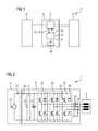
- a battery 4 and an electrical load in the form of a three-phase electric motor 6 via an electrical converter in the form of a three-phase inverter 8 are electrically connected to each other.
- the three-phase inverter 8 is accommodated in an inverter box 10.
- the circuit 2 may for example be part of a vehicle electrical system of a vehicle, not shown, in which the battery 4 as a rechargeable battery supplies the three-phase electric motor 6 as a drive unit of the vehicle with electrical energy.
- a battery voltage 12 is applied to the inverter 8.
- an intermediate circuit capacitor 14 is connected in parallel to the battery 4, which is charged by the battery voltage 12 to the battery voltage 12.
- the capacitor voltage 15 can be detected by a voltmeter 16, which is connected in parallel to the DC link capacitor 12.
- an ammeter 18 may be arranged, which detects the discharged from the battery 4 battery electric current 20.
- the inverter 8 includes three half-bridges 22 each generating an alternating current phase 24 for the three-phase electric motor 6 based on the battery current 20.
- Each half-bridge 22 has two series-connected switching elements, each switching element consisting of a switch 26, such as an IGBT (bipolar transistor with insulated gate electrode) and a freewheeling diode 28 connected in parallel thereto.
- a switch 26 such as an IGBT (bipolar transistor with insulated gate electrode)
- freewheeling diode 28 connected in parallel thereto.
- FIG. 2 only a switch 26 and a freewheeling diode 28 provided with a reference numeral.
- the magnitude of the currents in the AC phases 24 may be measured with a corresponding phase current meter 30. Since the sum of the measured values from the phase current meters 30 is zero, one of the alternating current phases 24 can be determined by calculation and, if appropriate, one of the phase current meters 30 can be dispensed with.
- the detected battery current 20 and the detected capacitor voltage 15 corresponding to the battery voltage 12 are provided to a device 32 in the inverter box 10 for monitoring the circuit 2.
- the device 32 is further provided to control the switches 26 of the inverter 8 based on drive signals 33.
- the device 32 checks based on the detected battery current 20 and the detected capacitor voltage 15 in a manner to be described, whether the circuit of the battery 4 and the electric motor 6 in the circuit 2 is faulty and has, for example, interruptions or short circuits.
- the device 32 outputs a corresponding error message 34.
- a fuse function 36 is actuated, which discharges the intermediate circuit capacitor 14 in a manner not shown.
- the device 32 determines the error message 34.
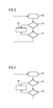
- FIG. 3 shows a first embodiment for determining the error message 34 with the device 32nd
- the device 32 cyclically varies the power flow through the circuit 2 in step 38 by means of the control signal 33, so that a comparatively small alternating current is superimposed in the circuit 2 whose peak-to-peak value can amount, for example, to 1% of the battery current.
- the device receives the capacitor voltage 15, which is detected by the voltmeter 16, and checks whether a pattern equivalent to the varied power flow is found in the capacitor voltage 15.
- the device 32 may, for example, correlate the pattern used to vary the power flow with the detected capacitor voltage 15.
- the capacitor voltage 15 can be multiplied by the pattern and then low-pass filtered. If the pattern in the capacitor voltage 15 is found as a result of the correlation, this is an indication that electrical power is transmitted to the electric motor 6 and no short circuit can be present. In this case, the device 32 continues the process at step 42. Alternatively, the device 32 outputs an error message 36 in step 44.
- step 42 the device 32 checks how high the fluctuations in the found pattern of the capacitor voltage 15 are. If the fluctuations exceed a certain threshold, then this is an indication that only the DC link capacitor 14 provides the electrical energy for the electric motor 6 and an interruption between the battery 4 and DC link capacitor 14 must be present. In this case, the device 32 outputs the error message 36 in step 44. If the fluctuations remain below the threshold, the device 32 determines that the functional state of the circuit 2 is error-free and restarts the process with step 38.
- FIG. 4 shows a second embodiment for determining the error message 34 with the device 32.
- FIG. 4 become too FIG. 3 same steps provided with the same reference numerals and not described again.
- Step 40 is replaced by Step 46 and Step 42 is replaced by Step 48.
- step 40 While in step 40, in the sensed capacitor voltage 15, the pattern of power flow variation has been sought, device 32 receives the battery current 20 in addition to the capacitor voltage in step 46 and calculates the impedance of the circuit between the link capacitor 14 and battery 4. The calculated impedance becomes compared against a lower threshold. If the calculated impedance is too low, this is an indication of a short circuit in the circuit between the DC link capacitor 14 and the battery 4 and the method accordingly outputs the error message 34 in step 44.
- step 48 is continued, in which the calculated impedance is compared against an upper threshold. If the calculated impedance is too high, this is an indication of an interruption in the circuit between the intermediate circuit capacitor 14 and the battery 4. The method also outputs the error message 34 in step 44 in this case. If the calculated impedance is between the lower and upper threshold values, the functional state of the circuit 2 is error-free and the method restarts with step 38.
Landscapes
- Engineering & Computer Science (AREA)
- Power Engineering (AREA)
- Transportation (AREA)
- Mechanical Engineering (AREA)
- Life Sciences & Earth Sciences (AREA)
- Sustainable Development (AREA)
- Sustainable Energy (AREA)
- Charge And Discharge Circuits For Batteries Or The Like (AREA)
Abstract
Description
Die Erfindung betrifft ein Verfahren zum Überwachen einer Schaltung aus einer Batterie und einem an die Batterie angeschlossenen elektrischen Verbraucher und eine Vorrichtung zur Durchführung des Verfahrens.The invention relates to a method for monitoring a circuit of a battery and an electrical consumer connected to the battery and a device for carrying out the method.
In Schaltungen, die in nicht stationären, beweglichen Vorrichtungen, wie beispielsweise einem Fahrzeug, untergebracht sind, werden in der Regel elektrische Verbraucher über eine Batterie mit elektrischer Energie versorgt. Dazu werden der elektrische Verbraucher und die Batterie zu einer Schaltung verbaut.In circuits that are housed in non-stationary, movable devices, such as a vehicle, usually electrical consumers are powered by a battery with electrical energy. For this purpose, the electrical load and the battery are installed in a circuit.
Ist in der Schaltung der leistungsführende Schaltkreis aus der Batterie und dem elektrischen Verbraucher fehlerhaft unterbrochen, kann er durch eine unbeabsichtigte Berührung beispielsweise durch Personen über einen Erdschluss geschlossen werden. Je nach Höhe der durch die Batterie abgegebenen Spannung können hier lebensgefährliche Ableitströme durch die berührende Person in Form von Körperströmen fließen. Sind im leistungsführenden Schaltkreis zwischen dem elektrischen Verbraucher und der Batterie ferner Zwischenspeicher, wie ein Zwischenkreiskondensator enthalten, müssen diese beispielsweise für Wartungszwecke beziehungsweise bei der Beseitigung von Fehlern nach dem Unterbrechen des leistungsführenden Schaltkreises aus Sicherheitsgründen entladen werden, damit beim Wartungspersonal bei Berührung des Zwischenspeichers keine gefährlichen Körperströme zum Fließen gebracht werden.If the power circuit of the battery and the electrical load is incorrectly interrupted in the circuit, it can be closed by an unintentional contact, for example by persons via a ground fault. Depending on the amount of voltage delivered by the battery, life-threatening leakage currents can flow through the touching person in the form of body currents. If the intermediate circuit, such as an intermediate circuit capacitor, is also contained in the power-conducting circuit between the electrical load and the battery, these must be discharged for safety purposes, for example for the purpose of repairing or eliminating errors after interrupting the power-carrying circuit, so that the maintenance personnel are not dangerous when the temporary storage device is touched Body currents are made to flow.
Daher muss der leistungsführende Schaltkreis hinsichtlich Unterbrechungen überwacht werden.Therefore, the high-performance circuit must be monitored for interruptions.
Aus der
Es ist Aufgabe die bekannte Schaltkreisüberwachung zu verbessern.It is the task to improve the known circuit monitoring.
Die Aufgabe wird durch die Merkmale der unabhängigen Ansprüche gelöst. Bevorzugte Weiterbildungen sind Gegenstand der abhängigen Ansprüche.The object is solved by the features of the independent claims. Preferred developments are the subject of the dependent claims.
Die Erfindung schlägt vor, basierend auf einer Variation des Leistungsflusses durch den Schaltkreis aus der Batterie und dem elektrischen Verbraucher und einer Reaktion der Schaltung mit der Batterie und dem elektrischen Verbraucher herauszufinden, ob der Schaltkreis unterbrochen ist.The invention proposes to find out, based on a variation of the power flow through the circuit of the battery and the electrical load and a reaction of the circuit with the battery and the electrical load, whether the circuit is interrupted.
Der Vorschlag basiert auf der Erkenntnis, dass bei einem geschlossenen leistungsführenden Schaltkreis Änderungen des Leistungsflusses zu plausiblen Reaktionen in der Schaltung führen müssen. Mit anderen Worten muss eine definierte Änderung des Leistungsflusses zwischen der Batterie und dem elektrischen Verbraucher zu einer überprüfbaren Reaktion der Schaltung führen, wenn der Schaltkreis zwischen Batterie und elektrischem Verbraucher geschlossen ist.The proposal is based on the finding that changes in the power flow must lead to plausible responses in the circuit when the power circuit is closed. In other words, a defined change in the power flow between the battery and the electrical load must lead to a verifiable reaction of the circuit when the circuit between the battery and the electrical load is closed.
Der Überlegung der Erfindung ist daher, eine definierte Änderung des Leistungsflusses festzulegen und die überprüfbare Reaktion zunächst beispielsweise rechnerisch zu bestimmen. Dann kann erfindungsgemäß in der Schaltung überprüft werden ob die überprüfbare Reaktion tatsächlich eintritt.The consideration of the invention is therefore to define a defined change in the power flow and to first determine the verifiable reaction, for example by calculation. Then, according to the invention, it can be checked in the circuit whether the testable reaction actually occurs.
Die Erfindung gibt daher ein Verfahren zum Überwachen einer Schaltung mit einer Batterie und einem an die Batterie angeschlossenen elektrischen Verbraucher an. Das angegebene Verfahren umfasst Variieren eines elektrischen Leistungsflusses zwischen der Batterie und dem elektrischen Verbraucher, Erfassen einer Reaktion der Schaltung auf die Variation und Bestimmen eines Fehlers, wenn die erfasste Reaktion von einer vorbestimmten Reaktion abweicht.The invention therefore provides a method of monitoring a circuit having a battery and an electrical consumer connected to the battery. The specified method includes varying an electrical power flow between the battery and the electrical load, detecting a response of the circuit to the variation and determining an error if the sensed response deviates from a predetermined response.
Als Reaktion können alle beliebigen elektrischen und physikalischen Größen in der Schaltung herangezogen werden, die vom Leistungsfluss zwischen der Batterie und dem elektrischen Verbraucher abhängen. Dies können beispielsweise die Werte des Gesamtwiderstands oder des Arbeitspunktes der Schaltung sein. Aber auch andere physikalische Größen, wie eine Wärmeentwicklung oder eine Störabstrahlung können zur erfindungsgemäßen Überwachung des Schaltkreises zwischen der Batterie und dem elektrischen Verbraucher herangezogen werden.In response, any electrical and physical quantities in the circuit that depend on the power flow between the battery and the electrical load can be used. These may be, for example, the values of the total resistance or the operating point of the circuit. However, other physical quantities, such as heat generation or interference emission, can also be used to monitor the circuit between the battery and the electrical consumer according to the invention.
Durch das angegebene Verfahren können Unterbrechungen des Schaltkreises zwischen der Batterie und dem elektrischen Verbraucher festgestellt werden, ohne dass ein zusätzlicher redundanter Schaltkreis, wie beispielsweise eine Pilotline beziehungsweise ein Hochvolt Interlock notwendig ist. Diese Elemente sind damit überflüssig und können vollständig weggelassen werden. Folglich reduziert die Erfindung die Herstellungskosten und die Baugrößen entsprechender Schaltungen.By the specified method, interruptions of the circuit between the battery and the electrical load can be determined without an additional redundant circuit, such as a pilot line or a high-voltage interlock is necessary. These elements are superfluous and can be completely omitted. Consequently, the invention reduces the manufacturing costs and the sizes of corresponding circuits.
Darüber hinaus kann das angegebenen Verfahren den Schaltkreis der Schaltung auch hinsichtlich einer wesentlich breiteren Anzahl an Fehlerquellen überwachen, da die Reaktion der Schaltung auf eine Variation des Leistungsflusses nicht nur im Falle einer Unterbrechung des Schaltkreises sondern auch im Falle anderer Fehler von der vorbestimmten Reaktion abweicht. Diese Fehler können beispielsweise Kurzschlüsse im Schaltkreis aber auch Bauteildrifteffekte sein, die altersbedingt beispielsweise an der Batterie oder dem elektrischen Verbraucher auftreten.Moreover, the disclosed method may also monitor the circuitry of the circuit with respect to a much wider variety of sources of error, since the response of the circuit to a variation in power flow will deviate from the predetermined response not only in the event of a circuit break, but also in the event of other errors. These faults can be, for example, shorts in the circuit but also component drift effects, which, for example, can occur at the battery or the electrical load due to age.
In einer Weiterbildung der Erfindung erfolgt die Variation des elektrischen Leistungsflusses mit einem bestimmten Muster. Dieses Muster ist beispielsweise mittels eines Signalgenerators nicht nur in einfacher erzeugbar, das Muster lässt sich auch problemlos an die Rahmenbedingungen der Schaltung anpassen, so dass die Schaltung durch die Variation des Leistungsflusses beispielsweise nicht in kritische Betriebszustände überführt wird, die die Schaltung schädigen oder gar zerstören können.In a development of the invention, the variation of the electrical power flow takes place with a specific pattern. This pattern is for example by means of a signal generator not only easier to produce, the pattern can also be easily adapted to the conditions of the circuit, so that the circuit is not transferred by the variation of the power flow, for example, in critical operating conditions that can damage the circuit or even destroy.
In einer zusätzlichen Weiterbildung umfasst das angegebene Verfahren den Schritt Erfassen einer die Schaltung beschreibenden elektrischen Größe und Suchen des Musters in der erfassten elektrischen Größe. Der Weiterbildung liegt der Gedanke zugrunde, dass im Falle von Unterbrechungen und Kurzschlüssen im Schaltkreis zwischen der Batterie und dem elektrischen Verbraucher keine elektrischen Leistungen übertragbar sind. Folglich führt eine Variation des Leistungsflusses auch zu keiner Reaktion des Schaltkreises. Das Muster kann daher nur dann in der Reaktion der Schaltung wiederzufinden sein, wenn die Schaltung frei von Unterbrechungen und Kurzschlüssen ist. Auf diese Weise lässt sich die Verifikation, ob die gemessene Reaktion von der vorbestimmten Reaktion abweicht, in besonders einfacher Weise durchführen, da die vorbestimmte Reaktion durch das verwendete Muster bereits bekannt ist und nicht erst definiert werden muss.In an additional development, the specified method comprises the step of detecting an electrical variable describing the circuit and searching for the pattern in the detected electrical quantity. The development is based on the idea that in the case of interruptions and short circuits in the circuit between the battery and the electrical load no electrical power can be transmitted. Consequently, a variation of the power flow also leads to no reaction of the circuit. The pattern can therefore only be found in the response of the circuit if the circuit is free of open circuits and short circuits. In this way, the verification of whether the measured reaction deviates from the predetermined reaction can be carried out in a particularly simple manner, since the predetermined reaction is already known by the pattern used and does not have to be defined first.
In einer bevorzugten Weiterbildung ist das Muster eine zyklische Variation des elektrischen Leistungsflusses. Die zyklische Variation kann jede beliebige Form, wie beispielsweise eine Sinus-Form oder eine pseudozufällige Form annehmen. Durch die Verwendung einer zyklischen Variation des Leistungsflusses kann die Suche nach dem Muster technisch besonders einfach umgesetzt werden, da die vorbestimmte Reaktion der Schaltung spektral begrenzt ist.In a preferred embodiment, the pattern is a cyclic variation of the electric power flow. The cyclic variation may take any form, such as a sine or a pseudo-random form. By using a cyclic variation of the power flow, the search for the pattern can be technically particularly easily implemented because the predetermined response of the circuit is spectrally limited.
In einer besonders bevorzugten Weiterbildung umfasst das angegebene Verfahren den Schritt Korrelieren der elektrischen Größe mit dem zyklischen elektrischen Leistungsfluss zum Suchen des Musters. Durch die Korrelation können effizient störende Signale wie Rauschanteile in der erfassten Reaktion gefiltert werden. Zudem ist das Verfahren dieser Weiterbildung in einfacher Weise mit bekannten Schaltungselementen, wie beispielsweise einem Lock-in-Verstärker umsetzbar, die kostengünstig und erprobt erhältlich sind.In a particularly preferred development, the specified method comprises the step of correlating the electrical variable with the cyclic electrical power flow for searching the pattern. Correlation efficiently filters interfering signals such as noise in the detected response become. In addition, the method of this development in a simple manner with known circuit elements, such as a lock-in amplifier can be implemented, which are available inexpensively and proven.
In einer anderen Ausführung umfasst das angegebene Verfahren den Schritt Ansteuern eines Schalters eines elektrischen Wandlers zur Variation des elektrischen Leistungsflusses, wobei der elektrische Wandler zum Umwandeln einer von der Batterie abgegebenen und an den elektrischen Verbraucher übertragenen elektrischen Leistung vorgesehen ist. Der elektrische Wandler ist in zahlreichen Applikation beispielsweise in Form eines Wechselrichters vorhanden. Seine Ansteuerung geschieht in der Regel rein elektronisch beispielsweise durch eine auf einem Ansteuerrechner ablaufende Ansteuersoftware. Diese Ansteuersoftware kann durch geeignete Modifikationen zur praktischen Umsetzung des angegebenen Verfahrens mitgenutzt werden, so dass keine zusätzlichen mechanischen oder anderweitigen strukturellen Gestaltungsmaßnahmen an der Schaltung notwendig sind, um die Erfindung zu realisieren. Überraschender Weise erlaubt es die angegebene Ausführung auch, herkömmliche, bereits existierende Schaltungen mit einem elektrischen Wandler aber ohne Pilotlines beziehungsweise Hochvolt Interlocks mit einer Sicherungsfunktion auszustatten, die die Schaltung auf Unterbrechungen oder andere Fehler, wie beispielsweise Kurzschlüsse hin überwacht.In another embodiment, the specified method comprises the step of driving a switch of an electrical converter for varying the electrical power flow, wherein the electrical converter is provided for converting an output from the battery and transmitted to the electrical load electrical power. The electrical converter is present in numerous applications, for example in the form of an inverter. Its control is usually purely electronic, for example, by a running on a control computer control software. This control software can be shared by suitable modifications for the practical implementation of the specified method, so that no additional mechanical or other structural design measures to the circuit are necessary to realize the invention. Surprisingly, the specified design also makes it possible to equip conventional, already existing circuits with an electrical converter but without pilot lines or high-voltage interlocks with a safety function which monitors the circuit for interruptions or other faults, such as short circuits.
In einer weiteren Ausführung der Erfindung umfasst das angegebene Verfahren den Schritt Entladen einer Kapazität basierend auf der Fehlermeldung, wobei die Kapazität vorgesehen ist, zwischen der Batterie und dem elektrischen Verbraucher übertragene elektrische Energie zwischenzuspeichern. Die energiespeichernde Kapazität kann insbesondere im Falle von Unterbrechungen in der Schaltung ein Sicherheitsrisiko darstellen, da sie gefährliche Spannungen führt, die sich wie eingangs erwähnt bei Berührung beispielsweise durch Personen über diese entladen können. Durch das angegebene Verfahren kann dieses Sicherheitsrisiko nicht nur erkannt sondern auch wirksam minimiert werden.In a further embodiment of the invention, the specified method comprises the step of discharging a capacitor based on the error message, the capacity being provided for temporarily storing electrical energy transmitted between the battery and the electrical load. The energy storage capacity can pose a security risk especially in the case of interruptions in the circuit, as it leads to dangerous voltages that can be discharged as mentioned above in contact, for example, by people on this. By the specified procedure This security risk can not only be recognized but also effectively minimized.
In einer Ausbildung der Erfindung umfasst das angegebene Verfahren den Schritt Bestimmen des Fehlers, wenn eine Schwankung der erfassten elektrischen Größe außerhalb eines vorbestimmten Bereichs für die Schwankung fällt. Der vorbestimmte Bereich für die Schwankung kann beispielsweise durch wenige Schwellenwerte vorgegeben werden, so dass die Fehlerbestimmung direkt mit einer Messgröße ohne weitere Signalumformungen durchführbar werden kann.In an embodiment of the invention, the specified method includes the step of determining the error when a fluctuation of the detected electrical quantity falls outside a predetermined range for the fluctuation. The predetermined range for the fluctuation can be predetermined, for example, by a few threshold values, so that the error determination can be carried out directly with a measured variable without further signal transformations.
In einer weiterführenden Ausbildung umfasst der vorbestimmte Bereich für die Schwankung einen Wert der elektrischen Größe, bei dem die Batterie einen elektrischen Prüfverbraucher, insbesondere einem Zwischenkreiskondensator, zwischen der Batterie und dem elektrischen Verbraucher mit elektrischer Energie speist. Dieser Ausbildung liegt die Überlegung zugrunde, dass im fehlerfreien Fall der Zwischenkreiskondensator von der Batterie mit elektrischer Energie versorgt wird. Im Unterbrechungsfall zur Batterie übernimmt der Zwischenkreiskondensator die elektrische Energieversorgung des Verbrauchers, was zu starken Schwankungen der Spannung am Zwischenkreiskondensator führt. Im Kurzschlussfall jedoch schwankt die Spannung am Zwischenkreiskondensator überhaupt nicht mehr, da auch der Zwischenkreiskondensator im Kurschlussfall keine elektrischen Leistungen mehr übertragen kann. Auf diese Weise kann eine Unterbrechung nicht nur erkannt sondern auch von einem Kurzschluss unterschieden werden.In a further development, the predetermined range for the fluctuation comprises a value of the electrical variable at which the battery feeds an electrical test consumer, in particular a DC link capacitor, between the battery and the electrical load with electrical energy. This training is based on the consideration that in the fault-free case, the DC link capacitor is supplied by the battery with electrical energy. In the event of an interruption to the battery, the DC link capacitor takes over the electrical power supply of the load, which leads to strong fluctuations in the voltage at the DC link capacitor. In the event of a short circuit, however, the voltage at the DC link capacitor no longer fluctuates at all, since even the DC link capacitor can no longer transmit any electrical power in the event of a short circuit. In this way, an interruption can not only be detected but also distinguished from a short circuit.
In einer anderen Ausbildung der Erfindung umfasst das angegebene Verfahren den Schritt Erfassen einer Impedanz der Schaltung und Bestimmen des Fehlers, wenn die Impedanz außerhalb eines vorbestimmten Bereichs fällt. Die zur Impedanzbe-rech¬nung notwendigen elektrischen Größen können in der Schaltung an einer beliebigen Stelle erfasst werden. Dies ist insbesondere für den Fall vorteilhaft, dass ein bereits erwähnter elektrischer Wandler eingesetzt wird, da seine Messwerterfassung zur Umsetzung des Verfahrens herangezogen werden kann, ohne dass die Schaltung strukturell verändert werden muss.In another embodiment of the invention, the specified method includes the step of detecting an impedance of the circuit and determining the error if the impedance falls outside a predetermined range. The electrical variables necessary for the impedance calculation can be detected at any point in the circuit. This is advantageous in particular for the case that an already mentioned electrical converter is used, since its measured value detection can be used to implement the method without the circuit must be structurally changed.
In einer bevorzugten Ausführung umfasst der vorbestimmte Bereich eine Impedanz, die einen Wert der Impedanz aus einer Zusammenschaltung der Batterie und des elektrischen Verbrauchers aufweist. Die Impedanz des vorbestimmten Bereichs kann damit den fehlerfreien Fall charakterisieren, wobei der Bereich beliebig mit Toleranzen behaftet werden kann, um eine ungewollte Erzeugung eines Fehlers zu vermeiden.In a preferred embodiment, the predetermined range includes an impedance having a value of impedance from an interconnection of the battery and the electrical load. The impedance of the predetermined range can thus characterize the error-free case, wherein the range can be arbitrarily subject to tolerances in order to avoid an unwanted generation of a fault.
In einer besonders bevorzugten Ausbildung der Erfindung ist aus dem Bereich eine Impedanz ausgeschlossen, die einen Wert der Impedanz der Batterie und/oder einen Wert des elektrischen Verbrauchers aufweist. Auf diese Weise können die Fehler, dass eine Unterbrechung zwischen Messinstrument und Batterie oder eine Unterbrechung zwischen Messinstrument und elektrischem Verbraucher vorliegt, ganz konkret bestimmt und im angegebenen Verfahren berücksichtigt werden.In a particularly preferred embodiment of the invention, an impedance is excluded from the range, which has a value of the impedance of the battery and / or a value of the electrical load. In this way, the errors that there is an interruption between meter and battery or an interruption between meter and electrical consumer can be determined quite concretely and taken into account in the specified method.
Die Erfindung gibt auch eine Vorrichtung an, die einen Speicher zum Speichern eines Programmcodes zur Ausführung eines angegebenen Verfahrens und einen Prozessor zum Ausführen des Programmcodes, wenn der Programmcode aus dem Speicher geladen ist, umfasst.The invention also provides a device comprising a memory for storing a program code for executing a specified method and a processor for executing the program code when the program code is loaded from the memory.
Die Erfindung gibt auch eine Schaltung an, die eine Batterie, einen elektrischen Verbraucher, einen elektrischen Wandler zum Speisen des elektrischen Verbrauchers mit der elektrischen Energie aus der Batterie und eine angegebene Vorrichtung umfasst.The invention also provides a circuit comprising a battery, an electrical load, an electrical converter for supplying the electrical load with the electrical energy from the battery and a specified device.
Die Erfindung gibt auch ein Fahrzeug an, das eine angegebene Schaltung umfasst, wobei der elektrische Verbraucher ein elektrischer Motor im Fahrzeug ist.The invention also provides a vehicle comprising a specified circuit, wherein the electrical load is an electric motor in the vehicle.
Die oben beschriebenen Eigenschaften, Merkmale und Vorteile dieser Erfindung sowie die Art und Weise, wie diese erreicht werden, werden klarer und deutlicher verständlich im Zusammenhang mit der folgenden Beschreibung des Ausführungsbeispiels, die im Zusammenhang mit den Zeichnungen näher erläutert werden, wobei:
- FIG 1
- eine Schaltung mit einer an die Schaltung angeschlossenen Vorrichtung gemäß der Erfindung,
- FIG 2
- eine Detaildarstellung des Netzwerks aus
FIG 1 , - FIG 3
- ein erstes Ausführungsbeispiel gemäß der Erfindung und
- FIG 4
- ein zweites Ausführungsbeispiel gemäß der Erfindung zeigen.
- FIG. 1
- a circuit with a device connected to the circuit according to the invention,
- FIG. 2
- a detailed view of the network
FIG. 1 . - FIG. 3
- a first embodiment according to the invention and
- FIG. 4
- show a second embodiment according to the invention.
Es wird auf die
In einer Schaltung 2 sind eine Batterie 4 und ein elektrischer Verbraucher in Form eines dreiphasigen Elektromotors 6 über einen elektrischen Wandler in Form eines dreiphasigen Wechselrichters 8 miteinander elektrisch verbunden. Der dreiphasige Wechselrichter 8 ist in einer Inverterbox 10 aufgenommen. Die Schaltung 2 kann beispielsweise Teil eines Bordnetzes eines nicht gezeigten Fahrzeuges sein, in der die Batterie 4 als wiederaufladbarer Akkumulator den dreiphasigen Elektromotor 6 als Antriebseinheit des Fahrzeugs mit elektrischer Energie versorgt.In a
Über die Batterie 4 ist an den Wechselrichter 8 eine Batteriespannung 12 angelegt. Im Wechselrichter 8 ist ein Zwischenkreiskondensator 14 parallel zur Batterie 4 geschaltet, der durch die Batteriespannung 12 auf die Batteriespannung 12 aufgeladen ist. Die Kondensatorspannung 15 kann durch einen Spannungsmesser 16 erfasst werden, der parallel zum Zwischenkreiskondensator 12 geschaltet ist. Zusätzlich kann im Strompfad zwischen der Batterie 4 und dem Zwischenkreiskondensator 12 ein Strommesser 18 angeordnet sein, der den von der Batterie 4 abgegebenen elektrischen Batteriestrom 20 erfasst.Via the
Der Wechselrichter 8 umfasst drei Halbbrücken 22, die je eine Wechselstromphase 24 für den dreiphasigen Elektromotor 6 basierend auf dem Batteriestrom 20 erzeugen. Jede Halbbrücke 22 weist zwei in Reihe geschaltete Schaltelemente, wobei jedes Schaltelement aus einem Schalter 26, wie beispielsweise einem IGBT (Bipolartransistor mit isolierter Gateelektrode) und einer dazu parallel geschalteten Freilaufdiode 28 besteht. Der Übersichtlichkeit halber ist in
Die Höhe der Ströme in den Wechselstromphasen 24 können mit einem entsprechenden Phasenstrommesser 30 gemessen werden. Da die Summe der Messwerte aus den Phasenstrommessern 30 Null ergibt kann eine der Wechselstromphasen 24 rechnerisch bestimmt und gegebenenfalls auf einen der Phasenstrommesser 30 verzichtet werden.The magnitude of the currents in the AC phases 24 may be measured with a corresponding phase
Der erfasste Batteriestrom 20 sowie die erfasste Kondensatorspannung 15, die der Batteriespannung 12 entspricht, werden einer Vorrichtung 32 in der Inverterbox 10 zum Überwachen der Schaltung 2 bereitgestellt. Die Vorrichtung 32 ist ferner vorgesehen, basierend auf Ansteuersignalen 33 die Schalter 26 des Wechselrichters 8 anzusteuern. In der vorliegenden Ausführungsform überprüft die Vorrichtung 32 basierend auf dem erfassten Batteriestrom 20 sowie der erfassten Kondensatorspannung 15 in einer noch zu beschreibenden Weise, ob der Schaltkreis aus der Batterie 4 und dem Elektromotor 6 in der Schaltung 2 fehlerhaft ist und beispielsweise Unterbrechungen oder Kurzschlüsse aufweist. Gegebenenfalls gibt die Vorrichtung 32 eine entsprechende Fehlermeldung 34 aus. In der vorliegenden Ausführung wird mit der Fehlermeldung 34 eine Sicherungsfunktion 36 angesteuert, die den Zwischenkreiskondensator 14 in einer nicht gezeigten Weise entlädt.The detected battery current 20 and the detected
Nachstehend wird anhand zweier Ausführungsbeispiele erläutert, wie die Vorrichtung 32 die Fehlermeldung 34 bestimmt.Below is explained with reference to two embodiments, as the
Zunächst variiert die Vorrichtung 32 in Schritt 38 mittels des Steuersignals 33 den Leistungsfluss durch die Schaltung 2 zyklisch, so dass in der Schaltung 2 ein vergleichsweise kleiner Wechselstrom überlagert wird, dessen Spitze-zu-Spitze Wert beispielsweise 1% des Batteriestromes betragen kann.First, the
In Schritt 40 empfängt die Vorrichtung die Kondensatorspannung 15, die vom Spannungsmessgerät 16 erfasst wird und überprüft, ob in der Kondensatorspannung 15 ein dem variierten Leistungsfluss äquivalentes Muster zu finden ist. Dazu kann die Vorrichtung 32 beispielsweise das zur Variation des Leistungsflusses verwendete Muster mit der erfassten Kondensatorspannung 15 korrelieren. Zur Korrelation kann die Kondensatorspannung 15 mit dem Muster multipliziert und anschließend tiefpassgefiltert werden. Findet sich das Muster in der Kondensatorspannung 15 als Ergebnis der Korrelation, so ist das ein Hinweis darauf, dass elektrische Leistung zum Elektromotor 6 übertragen wird und kein Kurzschluss vorhanden sein kann. In diesem Fall führt die Vorrichtung 32 das Verfahren mit Schritt 42 fort. Alternativ gibt die Vorrichtung 32 in Schritt 44 eine Fehlermeldung 36 aus.In
In Schritt 42 überprüft die Vorrichtung 32, wie hoch die Schwankungen im gefundenen Muster der Kondensatorspannung 15 sind. Überschreiten die Schwankungen einen bestimmten Schwellenwert, so ist das ein Hinweis darauf, dass allein der Zwischenkreiskondensator 14 die elektrische Energie für den Elektromotor 6 bereitstellt und eine Unterbrechung zwischen Batterie 4 und Zwischenkreiskondensator 14 vorhanden sein muss. In diesem Fall gibt die Vorrichtung 32 in Schritt 44 die Fehlermeldung 36 aus. Bleiben die Schwankungen unterhalb des Schwellenwertes, so bestimmt die Vorrichtung 32, dass der Funktionszustand der Schaltung 2 fehlerfrei ist und startet das Verfahren erneut mit Schritt 38.In
In
Während im Schritt 40 in der erfassten Kondensatorspannung 15 das Muster der Variation des Leistungsflusses gesucht wurde, empfängt die Vorrichtung 32 neben der Kondensatorspannung im Schritt 46 den Batteriestrom 20 und berechnet die Impedanz des Stromkreises zwischen dem Zwischenkreiskondensator 14 und der Batterie 4. Die berechnete Impedanz wird gegen einen unteren Schwellenwert verglichen. Ist die berechnete Impedanz zu niedrig, so ist das ein Hinweis auf einen Kurzschluss im Stromkreis zwischen dem Zwischenkreiskondensator 14 und der Batterie 4 und das Verfahren gibt entsprechend in Schritt 44 die Fehlermeldung 34 aus.While in
Andernfalls wird mit Schritt 48 weiter verfahren, in dem die berechnete Impedanz gegen einen oberen Schwellenwert verglichen wird. Ist die berechnete Impedanz zu hoch, so ist das ein Hinweis auf eine Unterbrechung im Stromkreis zwischen dem Zwischenkreiskondensator 14 und der Batterie 4. Das Verfahren gibt in diesem Fall ebenfalls die Fehlermeldung 34 in Schritt 44 aus. Wenn die berechnete Impedanz zwischen dem unteren und oberen Schwellenwert liegt, so ist der Funktionszustand der Schaltung 2 fehlerfrei und das Verfahren startet erneut mit Schritt 38.Otherwise, step 48 is continued, in which the calculated impedance is compared against an upper threshold. If the calculated impedance is too high, this is an indication of an interruption in the circuit between the intermediate circuit capacitor 14 and the
Obwohl die Erfindung im Detail durch das bevorzugte Ausführungsbeispiel näher illustriert und beschrieben wurde, so ist die Erfindung nicht durch die offenbarten Beispiele eingeschränkt und andere Variationen können vom Fachmann hieraus abgeleitet werden, ohne den Schutzumfang der Erfindung zu verlassen.Although the invention has been further illustrated and described in detail by the preferred embodiment, the invention is not limited by the disclosed examples, and other variations can be derived therefrom by those skilled in the art without departing from the scope of the invention.
Claims (15)
Priority Applications (1)
| Application Number | Priority Date | Filing Date | Title |
|---|---|---|---|
| EP11182737A EP2572921A1 (en) | 2011-09-26 | 2011-09-26 | Circuit monitoring |
Applications Claiming Priority (1)
| Application Number | Priority Date | Filing Date | Title |
|---|---|---|---|
| EP11182737A EP2572921A1 (en) | 2011-09-26 | 2011-09-26 | Circuit monitoring |
Publications (1)
| Publication Number | Publication Date |
|---|---|
| EP2572921A1 true EP2572921A1 (en) | 2013-03-27 |
Family
ID=44720686
Family Applications (1)
| Application Number | Title | Priority Date | Filing Date |
|---|---|---|---|
| EP11182737A Withdrawn EP2572921A1 (en) | 2011-09-26 | 2011-09-26 | Circuit monitoring |
Country Status (1)
| Country | Link |
|---|---|
| EP (1) | EP2572921A1 (en) |
Citations (7)
| Publication number | Priority date | Publication date | Assignee | Title |
|---|---|---|---|---|
| US20020121902A1 (en) * | 2001-01-11 | 2002-09-05 | Nissan Motor Co., Ltd. | Ground detection apparatus for electric vehicle |
| DE102005061018A1 (en) * | 2005-12-19 | 2007-06-21 | Daimlerchrysler Ag | Connection testing device and method for loudspeakers in audio system as in a motor vehicle and data carrier has test signal generator with condition monitor and correlation of actual and ideal values |
| US20070229091A1 (en) * | 2006-03-21 | 2007-10-04 | Kumar Ajith K | Method, apparatus and computer-readable code for detecting an incipient ground fault in an electrical propulsion system |
| EP1903651A1 (en) * | 2005-07-12 | 2008-03-26 | Komatsu Ltd. | Leakage detector of vehicle-mounted power supply system |
| US20100244850A1 (en) * | 2009-03-31 | 2010-09-30 | Honda Motor Co., Ltd. | Electric vehicle with ground fault detecting system |
| DE102009020178A1 (en) | 2009-05-06 | 2010-11-11 | Continental Automotive Gmbh | System for storing energy |
| WO2011104848A1 (en) * | 2010-02-25 | 2011-09-01 | 三菱電機株式会社 | Power conversion device |
-
2011
- 2011-09-26 EP EP11182737A patent/EP2572921A1/en not_active Withdrawn
Patent Citations (7)
| Publication number | Priority date | Publication date | Assignee | Title |
|---|---|---|---|---|
| US20020121902A1 (en) * | 2001-01-11 | 2002-09-05 | Nissan Motor Co., Ltd. | Ground detection apparatus for electric vehicle |
| EP1903651A1 (en) * | 2005-07-12 | 2008-03-26 | Komatsu Ltd. | Leakage detector of vehicle-mounted power supply system |
| DE102005061018A1 (en) * | 2005-12-19 | 2007-06-21 | Daimlerchrysler Ag | Connection testing device and method for loudspeakers in audio system as in a motor vehicle and data carrier has test signal generator with condition monitor and correlation of actual and ideal values |
| US20070229091A1 (en) * | 2006-03-21 | 2007-10-04 | Kumar Ajith K | Method, apparatus and computer-readable code for detecting an incipient ground fault in an electrical propulsion system |
| US20100244850A1 (en) * | 2009-03-31 | 2010-09-30 | Honda Motor Co., Ltd. | Electric vehicle with ground fault detecting system |
| DE102009020178A1 (en) | 2009-05-06 | 2010-11-11 | Continental Automotive Gmbh | System for storing energy |
| WO2011104848A1 (en) * | 2010-02-25 | 2011-09-01 | 三菱電機株式会社 | Power conversion device |
Similar Documents
| Publication | Publication Date | Title |
|---|---|---|
| EP1909368B1 (en) | Switching assembly and method for insulation monitoring for converter applications | |
| DE102013227174B4 (en) | Device and method for determining an insulation resistance of a photovoltaic system | |
| EP3394948B1 (en) | Inverter having network separation point and insulation resistance measurement, and method for measuring an insulation resistance | |
| EP2578876B1 (en) | Pitch system for a wind energy assembly and method for operating the same | |
| DE102016202021B3 (en) | Method and devices for detecting a break in a protective conductor connection | |
| DE102013217748B4 (en) | Multifunctional monitoring of electrical systems in a motor vehicle | |
| EP2837012B1 (en) | Method for checking a separation point of a photovoltaic inverter, and photovoltaic inverter | |
| DE112016001332T5 (en) | Multiphase converter | |
| AT513866B1 (en) | Method for testing a separation point of a photovoltaic inverter and photovoltaic inverter | |
| DE102013209142A1 (en) | Method for determining an insulation resistance of a power supply network of a vehicle comprising several subnetworks | |
| EP2637028B1 (en) | Assembly and device for testing high voltage batteries | |
| DE102011107734B4 (en) | Circuit arrangement for switching a relay to a safe switching state | |
| EP2553482B1 (en) | Vehicle electrical circuit and control device for this circuit | |
| DE102011121197B4 (en) | Procedure for commissioning an inverter and inverter | |
| EP3894874A1 (en) | Circuit assembly for fault detection in an ungrounded high-voltage system | |
| EP3824524B1 (en) | Method for testing a disconnection point of a photovoltaic converter and such a photovoltaic converter | |
| WO2022112393A1 (en) | Monitoring device for emergency standby operation | |
| EP2572921A1 (en) | Circuit monitoring | |
| DE102021104535A1 (en) | Method for monitoring the energy supply of a motor vehicle | |
| DE102017215981A1 (en) | A method for operating a priority circuit for coupling at least one consumer output with at least two source inputs and priority switching | |
| DE102017205477A1 (en) | Diagnostic method for an inverter, inverter arrangement and electric drive system | |
| DE102020211760A1 (en) | Method for discharging interference suppression capacitors in an unearthed power supply network | |
| DE102013219748A1 (en) | Electric drive system of an electrically driven vehicle and its testing | |
| DE102015006608B4 (en) | Method for operating a photovoltaic device of a motor vehicle and motor vehicle | |
| DE102015204220A1 (en) | Method for determining a DC link capacity and electric drive system |
Legal Events
| Date | Code | Title | Description |
|---|---|---|---|
| PUAI | Public reference made under article 153(3) epc to a published international application that has entered the european phase |
Free format text: ORIGINAL CODE: 0009012 |
|
| AK | Designated contracting states |
Kind code of ref document: A1 Designated state(s): AL AT BE BG CH CY CZ DE DK EE ES FI FR GB GR HR HU IE IS IT LI LT LU LV MC MK MT NL NO PL PT RO RS SE SI SK SM TR |
|
| AX | Request for extension of the european patent |
Extension state: BA ME |
|
| 17P | Request for examination filed |
Effective date: 20130705 |
|
| RBV | Designated contracting states (corrected) |
Designated state(s): AL AT BE BG CH CY CZ DE DK EE ES FI FR GB GR HR HU IE IS IT LI LT LU LV MC MK MT NL NO PL PT RO RS SE SI SK SM TR |
|
| 17Q | First examination report despatched |
Effective date: 20170131 |
|
| RAP1 | Party data changed (applicant data changed or rights of an application transferred) |
Owner name: SIEMENS AKTIENGESELLSCHAFT |
|
| STAA | Information on the status of an ep patent application or granted ep patent |
Free format text: STATUS: THE APPLICATION IS DEEMED TO BE WITHDRAWN |
|
| 18D | Application deemed to be withdrawn |
Effective date: 20170613 |