EP2572363B1 - Inductive power transfer system primary track topologies - Google Patents
Inductive power transfer system primary track topologies Download PDFInfo
- Publication number
- EP2572363B1 EP2572363B1 EP11783803.7A EP11783803A EP2572363B1 EP 2572363 B1 EP2572363 B1 EP 2572363B1 EP 11783803 A EP11783803 A EP 11783803A EP 2572363 B1 EP2572363 B1 EP 2572363B1
- Authority
- EP
- European Patent Office
- Prior art keywords
- track
- phase
- ipt
- multiphase
- conductor
- Prior art date
- Legal status (The legal status is an assumption and is not a legal conclusion. Google has not performed a legal analysis and makes no representation as to the accuracy of the status listed.)
- Active
Links
- 238000012546 transfer Methods 0.000 title claims description 39
- 230000001939 inductive effect Effects 0.000 title claims description 15
- 239000004020 conductor Substances 0.000 claims description 99
- 229910000859 α-Fe Inorganic materials 0.000 claims description 37
- 230000008878 coupling Effects 0.000 claims description 28
- 238000010168 coupling process Methods 0.000 claims description 28
- 238000005859 coupling reaction Methods 0.000 claims description 28
- 230000001419 dependent effect Effects 0.000 claims description 3
- 239000011295 pitch Substances 0.000 description 48
- 230000004907 flux Effects 0.000 description 41
- 238000004088 simulation Methods 0.000 description 16
- 230000001965 increasing effect Effects 0.000 description 15
- 238000010276 construction Methods 0.000 description 14
- 230000000694 effects Effects 0.000 description 12
- 238000013461 design Methods 0.000 description 10
- 238000013459 approach Methods 0.000 description 8
- 239000000463 material Substances 0.000 description 8
- 230000016507 interphase Effects 0.000 description 7
- 230000035699 permeability Effects 0.000 description 7
- 230000008901 benefit Effects 0.000 description 6
- 238000010586 diagram Methods 0.000 description 6
- 238000004804 winding Methods 0.000 description 6
- RYGMFSIKBFXOCR-UHFFFAOYSA-N Copper Chemical compound [Cu] RYGMFSIKBFXOCR-UHFFFAOYSA-N 0.000 description 5
- 239000010949 copper Substances 0.000 description 5
- 229910052802 copper Inorganic materials 0.000 description 5
- 239000007787 solid Substances 0.000 description 5
- 239000003990 capacitor Substances 0.000 description 4
- 238000000034 method Methods 0.000 description 4
- 238000000926 separation method Methods 0.000 description 4
- 239000013598 vector Substances 0.000 description 4
- 230000008859 change Effects 0.000 description 3
- 125000006850 spacer group Chemical group 0.000 description 3
- 230000001360 synchronised effect Effects 0.000 description 3
- 238000012360 testing method Methods 0.000 description 3
- 241000985610 Forpus Species 0.000 description 2
- 239000004411 aluminium Substances 0.000 description 2
- XAGFODPZIPBFFR-UHFFFAOYSA-N aluminium Chemical compound [Al] XAGFODPZIPBFFR-UHFFFAOYSA-N 0.000 description 2
- 229910052782 aluminium Inorganic materials 0.000 description 2
- 230000006872 improvement Effects 0.000 description 2
- 230000006698 induction Effects 0.000 description 2
- 238000005259 measurement Methods 0.000 description 2
- 241001522296 Erithacus rubecula Species 0.000 description 1
- 241000156302 Porcine hemagglutinating encephalomyelitis virus Species 0.000 description 1
- 229910000831 Steel Inorganic materials 0.000 description 1
- 230000015556 catabolic process Effects 0.000 description 1
- 238000002485 combustion reaction Methods 0.000 description 1
- 238000006880 cross-coupling reaction Methods 0.000 description 1
- 230000007423 decrease Effects 0.000 description 1
- 238000006731 degradation reaction Methods 0.000 description 1
- 230000005674 electromagnetic induction Effects 0.000 description 1
- 239000003344 environmental pollutant Substances 0.000 description 1
- 238000002474 experimental method Methods 0.000 description 1
- 238000000605 extraction Methods 0.000 description 1
- 230000002349 favourable effect Effects 0.000 description 1
- 239000002803 fossil fuel Substances 0.000 description 1
- 238000010438 heat treatment Methods 0.000 description 1
- 238000009434 installation Methods 0.000 description 1
- 230000002452 interceptive effect Effects 0.000 description 1
- 238000012423 maintenance Methods 0.000 description 1
- 238000004519 manufacturing process Methods 0.000 description 1
- 238000005007 materials handling Methods 0.000 description 1
- PEGJUOKGCQTYPH-UHFFFAOYSA-N n-(1,3-dimethylpyrazolo[3,4-b]quinolin-4-yl)-n',n'-dimethylpropane-1,3-diamine Chemical compound C1=CC=C2C(NCCCN(C)C)=C(C(C)=NN3C)C3=NC2=C1 PEGJUOKGCQTYPH-UHFFFAOYSA-N 0.000 description 1
- 238000005457 optimization Methods 0.000 description 1
- 230000037361 pathway Effects 0.000 description 1
- 230000035515 penetration Effects 0.000 description 1
- 230000010363 phase shift Effects 0.000 description 1
- 231100000719 pollutant Toxicity 0.000 description 1
- 239000000843 powder Substances 0.000 description 1
- 230000001105 regulatory effect Effects 0.000 description 1
- 239000010959 steel Substances 0.000 description 1
Images


Classifications
-
- H—ELECTRICITY
- H01—ELECTRIC ELEMENTS
- H01F—MAGNETS; INDUCTANCES; TRANSFORMERS; SELECTION OF MATERIALS FOR THEIR MAGNETIC PROPERTIES
- H01F38/00—Adaptations of transformers or inductances for specific applications or functions
- H01F38/14—Inductive couplings
-
- H02J5/005—
-
- B—PERFORMING OPERATIONS; TRANSPORTING
- B60—VEHICLES IN GENERAL
- B60L—PROPULSION OF ELECTRICALLY-PROPELLED VEHICLES; SUPPLYING ELECTRIC POWER FOR AUXILIARY EQUIPMENT OF ELECTRICALLY-PROPELLED VEHICLES; ELECTRODYNAMIC BRAKE SYSTEMS FOR VEHICLES IN GENERAL; MAGNETIC SUSPENSION OR LEVITATION FOR VEHICLES; MONITORING OPERATING VARIABLES OF ELECTRICALLY-PROPELLED VEHICLES; ELECTRIC SAFETY DEVICES FOR ELECTRICALLY-PROPELLED VEHICLES
- B60L5/00—Current collectors for power supply lines of electrically-propelled vehicles
- B60L5/005—Current collectors for power supply lines of electrically-propelled vehicles without mechanical contact between the collector and the power supply line
-
- B—PERFORMING OPERATIONS; TRANSPORTING
- B60—VEHICLES IN GENERAL
- B60L—PROPULSION OF ELECTRICALLY-PROPELLED VEHICLES; SUPPLYING ELECTRIC POWER FOR AUXILIARY EQUIPMENT OF ELECTRICALLY-PROPELLED VEHICLES; ELECTRODYNAMIC BRAKE SYSTEMS FOR VEHICLES IN GENERAL; MAGNETIC SUSPENSION OR LEVITATION FOR VEHICLES; MONITORING OPERATING VARIABLES OF ELECTRICALLY-PROPELLED VEHICLES; ELECTRIC SAFETY DEVICES FOR ELECTRICALLY-PROPELLED VEHICLES
- B60L53/00—Methods of charging batteries, specially adapted for electric vehicles; Charging stations or on-board charging equipment therefor; Exchange of energy storage elements in electric vehicles
- B60L53/10—Methods of charging batteries, specially adapted for electric vehicles; Charging stations or on-board charging equipment therefor; Exchange of energy storage elements in electric vehicles characterised by the energy transfer between the charging station and the vehicle
- B60L53/12—Inductive energy transfer
-
- B—PERFORMING OPERATIONS; TRANSPORTING
- B60—VEHICLES IN GENERAL
- B60L—PROPULSION OF ELECTRICALLY-PROPELLED VEHICLES; SUPPLYING ELECTRIC POWER FOR AUXILIARY EQUIPMENT OF ELECTRICALLY-PROPELLED VEHICLES; ELECTRODYNAMIC BRAKE SYSTEMS FOR VEHICLES IN GENERAL; MAGNETIC SUSPENSION OR LEVITATION FOR VEHICLES; MONITORING OPERATING VARIABLES OF ELECTRICALLY-PROPELLED VEHICLES; ELECTRIC SAFETY DEVICES FOR ELECTRICALLY-PROPELLED VEHICLES
- B60L53/00—Methods of charging batteries, specially adapted for electric vehicles; Charging stations or on-board charging equipment therefor; Exchange of energy storage elements in electric vehicles
- B60L53/30—Constructional details of charging stations
-
- B—PERFORMING OPERATIONS; TRANSPORTING
- B60—VEHICLES IN GENERAL
- B60M—POWER SUPPLY LINES, AND DEVICES ALONG RAILS, FOR ELECTRICALLY- PROPELLED VEHICLES
- B60M7/00—Power lines or rails specially adapted for electrically-propelled vehicles of special types, e.g. suspension tramway, ropeway, underground railway
- B60M7/003—Power lines or rails specially adapted for electrically-propelled vehicles of special types, e.g. suspension tramway, ropeway, underground railway for vehicles using stored power (e.g. charging stations)
-
- H—ELECTRICITY
- H02—GENERATION; CONVERSION OR DISTRIBUTION OF ELECTRIC POWER
- H02J—CIRCUIT ARRANGEMENTS OR SYSTEMS FOR SUPPLYING OR DISTRIBUTING ELECTRIC POWER; SYSTEMS FOR STORING ELECTRIC ENERGY
- H02J50/00—Circuit arrangements or systems for wireless supply or distribution of electric power
- H02J50/10—Circuit arrangements or systems for wireless supply or distribution of electric power using inductive coupling
- H02J50/12—Circuit arrangements or systems for wireless supply or distribution of electric power using inductive coupling of the resonant type
-
- Y—GENERAL TAGGING OF NEW TECHNOLOGICAL DEVELOPMENTS; GENERAL TAGGING OF CROSS-SECTIONAL TECHNOLOGIES SPANNING OVER SEVERAL SECTIONS OF THE IPC; TECHNICAL SUBJECTS COVERED BY FORMER USPC CROSS-REFERENCE ART COLLECTIONS [XRACs] AND DIGESTS
- Y02—TECHNOLOGIES OR APPLICATIONS FOR MITIGATION OR ADAPTATION AGAINST CLIMATE CHANGE
- Y02T—CLIMATE CHANGE MITIGATION TECHNOLOGIES RELATED TO TRANSPORTATION
- Y02T10/00—Road transport of goods or passengers
- Y02T10/60—Other road transportation technologies with climate change mitigation effect
- Y02T10/70—Energy storage systems for electromobility, e.g. batteries
-
- Y—GENERAL TAGGING OF NEW TECHNOLOGICAL DEVELOPMENTS; GENERAL TAGGING OF CROSS-SECTIONAL TECHNOLOGIES SPANNING OVER SEVERAL SECTIONS OF THE IPC; TECHNICAL SUBJECTS COVERED BY FORMER USPC CROSS-REFERENCE ART COLLECTIONS [XRACs] AND DIGESTS
- Y02—TECHNOLOGIES OR APPLICATIONS FOR MITIGATION OR ADAPTATION AGAINST CLIMATE CHANGE
- Y02T—CLIMATE CHANGE MITIGATION TECHNOLOGIES RELATED TO TRANSPORTATION
- Y02T10/00—Road transport of goods or passengers
- Y02T10/60—Other road transportation technologies with climate change mitigation effect
- Y02T10/7072—Electromobility specific charging systems or methods for batteries, ultracapacitors, supercapacitors or double-layer capacitors
-
- Y—GENERAL TAGGING OF NEW TECHNOLOGICAL DEVELOPMENTS; GENERAL TAGGING OF CROSS-SECTIONAL TECHNOLOGIES SPANNING OVER SEVERAL SECTIONS OF THE IPC; TECHNICAL SUBJECTS COVERED BY FORMER USPC CROSS-REFERENCE ART COLLECTIONS [XRACs] AND DIGESTS
- Y02—TECHNOLOGIES OR APPLICATIONS FOR MITIGATION OR ADAPTATION AGAINST CLIMATE CHANGE
- Y02T—CLIMATE CHANGE MITIGATION TECHNOLOGIES RELATED TO TRANSPORTATION
- Y02T90/00—Enabling technologies or technologies with a potential or indirect contribution to GHG emissions mitigation
- Y02T90/10—Technologies relating to charging of electric vehicles
- Y02T90/12—Electric charging stations
-
- Y—GENERAL TAGGING OF NEW TECHNOLOGICAL DEVELOPMENTS; GENERAL TAGGING OF CROSS-SECTIONAL TECHNOLOGIES SPANNING OVER SEVERAL SECTIONS OF THE IPC; TECHNICAL SUBJECTS COVERED BY FORMER USPC CROSS-REFERENCE ART COLLECTIONS [XRACs] AND DIGESTS
- Y02—TECHNOLOGIES OR APPLICATIONS FOR MITIGATION OR ADAPTATION AGAINST CLIMATE CHANGE
- Y02T—CLIMATE CHANGE MITIGATION TECHNOLOGIES RELATED TO TRANSPORTATION
- Y02T90/00—Enabling technologies or technologies with a potential or indirect contribution to GHG emissions mitigation
- Y02T90/10—Technologies relating to charging of electric vehicles
- Y02T90/14—Plug-in electric vehicles
Definitions
- This invention relates to Inductive Power Transfer (IPT) systems.
- the invention has particular relevance to multiphase IPT systems.
- IPT uses a varying magnetic field to couple power across an air gap, to a load, without physical contact.
- the air gap is present between a primary conductor such as an elongate loop of conductive material (generally referred to in this document as a track), and one or more pick-up devices that have a secondary coil which receive power from the magnetic field associated with the track.
- a primary conductor such as an elongate loop of conductive material (generally referred to in this document as a track)
- pick-up devices that have a secondary coil which receive power from the magnetic field associated with the track.
- System performance is not affected by wet or dirty environments and there are no safety risks under such conditions since the components are completely isolated.
- IPT is reliable and maintenance free unlike conventional plug or brush and bar contact based methods such as those used on trams and electric buses. IPT is presently used in numerous industrial applications such as materials handling and integrated circuit fabrication.
- IPT systems vary in capacity from 1W-200kW and can be used to both power and recharge robots, Automatic Guided Vehicles (AGV), electronic devices, recreational people movers, buses and Electric Vehicles (EVs).
- AGV Automatic Guided Vehicles
- EVs Electric Vehicles
- IPT systems may be divided into two distinct types: distributed systems that consist of one or more movable loads that may be placed anywhere on a track, and lumped systems that only allow power transfer at a defined location.
- EVs help reduce dependence on fossil fuels, emission of greenhouse gasses and emission of pollutants. Consequently, uptake of EVs has been increasing since the 1990's however market penetration has been low because EVs are not as cost effective as conventional vehicles.
- the present EV market is dominated by hybrid vehicles that derive their energy from a combustion engine, however, plug-in EVs (PHEV) have recently been introduced enabling energy from the grid to mitigate gasoline consumption.
- PHEV plug-in EVs
- major improvements are required in battery life and cost, and grid connection. The latter allows opportunistic charging after each trip rather than a long charge at the end of the day. As a result battery wear is significantly reduced by minimising the depth of discharge and the EV has a lower cost since a smaller battery is required.
- the preferred solution, that makes EVs more cost effective than gasoline vehicles is to power and recharge the EV via the road. It should be noted that the infrastructure for such a dynamic charging system could be relatively small because travel on interstate highways makes up 1% of roadway miles but carries 22% of all vehicle miles travelled. An EV that has 50% of its driven miles connected to a dynamic charging system would be as cost effective as a conventional vehicle and does not incur additional gasoline costs.
- An IPT system comprises three main components that are shown for a single phase system in Figure 1 .
- the power supply produces a sinusoidal current (typically in the 10-100 kHz frequency range for medium to high power systems) that drives a current (I 1 ) in an inductive primary conductive path, or track.
- the parallel compensation capacitor C 1 allows the track current, I 1 , to resonate, increasing the magnetic field strength in the vicinity of the track. This minimises the VA rating of the power supply for a given load.
- the track and secondary receiver device to which power from the track is transferred inductively act as a loosely coupled transformer enabling power transfer over relatively large air gaps.
- the receiver is commonly referred to as an IPT Pick-up (PU) and has an inductance, L 2 , which is tuned for resonance at the frequency of the current in the track using C 2 . This compensates for the relatively large PU leakage inductance.
- the voltage across C 2 is rectified and a switched mode controller enables the resonant tank to operate at a defined quality factor, Q, to boost power transfer and provide a usable DC output.
- the power output of an IPT system ( P out ) is quantified by the open circuit voltage ( V oc ) and short circuit current ( I sc ) of the PU as well as the PU circuit quality factor, as shown in (1).
- P su is the uncompensated power
- ⁇ is the angular frequency of the track current I 1
- M is the mutual inductance between the track and PU.
- the output power is dependent on the power supply ( ⁇ I 1 2 ), magnetic coupling ( M 2 / L 2 ) and PU controller (Q).
- ⁇ I 1 2 the power supply
- M 2 / L 2 magnetic coupling
- Q PU controller
- Increasing the power output and separation between the track and PU is highly desirable but efficiency is limited by the operational frequency (switching loss) and current rating (copper loss) of the system. Allowing a system to operate at a high Q boosts power transfer but in practical applications it is normally designed to operate between 4 and 6 due to component VA ratings and tolerances. Due to these limits, the greatest increase in system performance can be achieved by good magnetic design.
- the system was built before modem ferrites and power electronic components were developed, and this is reflected in its performance.
- the air gap between the track and PU was controlled by an electronic actuator to be 30mm and full power could be supplied up to an offset of 120mm from the track centre.
- the relatively low horizontal tolerance necessitated an automatic guidance system.
- a three phase track topology as shown in Fig.2 (a) was proposed by G. A. Covic, J. T. Boys, M. L. G. Kissin and H. G. Lu, in "A Three-Phase Inductive Power Transfer System for Roadway-Powered Vehicles," Industrial Electronics, IEEE Transactions on, vol. 54, no. 6, pp. 3370-3378, 2007 .
- the vehicle drives along the length of the track, Tx, which is referred to as the x-axis.
- the system uses an inductor-capacitor-inductor (LCL) impedance converting network that converts the voltage sourced inverter into a current source suitable for driving the inductive track.
- LCL inductor-capacitor-inductor
- the leakage inductance of the isolating transformer is used as the first inductor and the track forms the last inductor, so that only real power passes through the transformer.
- Large reactive currents (I 1 in Figure 1 ) circulate in the track and capacitor only.
- Three individual isolating transformers connected in a delta-delta configuration were used for each phase, however the output terminals of the transformers were connected directly to the start and return of each track loop resulting in a six wire track. This track topology is termed "bipolar" in this document because the PU is exposed to both forward and returning currents to the supply.
- WO2010/031595 describes a track for inductively transferring energy to a vehicle.
- M. L. G. Kissin, J. T. Boys and G_ A. Covic Interphase Mutual Inductive Power Transfer Systems," Industrial Electronics, IEEE Transactions on, vol_ 56, no_ 7, pp_ 2393-2400, 2009 discloses a roadway for powering electric vehicles using electromagnetic induction.
- the invention broadly provides a multiphase IPT primary track conductor arrangement as defined in claim 1 comprising a first phase conductor and a second phase conductor, the phase conductors being arranged substantially in a plane and so as to overlap each other and being arranged such that there is substantially balanced mutual coupling between the phase conductors; wherein the phase conductors extend longitudinally in the plane in a first dimension and a plurality of lengths of each phase conductor extend across the plane substantially transversely relative to the first dimension, the transverse lengths being substantially parallel to each other and spaced from each other; wherein the transverse lengths of each phase conductor are grouped in pairs so that current will flow in the same direction through each pair; and wherein each phase conductor comprises a forward and return conductor to carry forward and reverse currents.
- a multiphase inductive power transfer system is provided as defined in claim 7.
- a two-phase bipolar IPT system is shown in Figure 2 .
- the track 1 consists of two extended loops 1A and 1B comprising four cables.
- the track loops are each driven by an independent inverter 2A and 2B respectively, and carry currents which are equal in frequency and magnitude, but electrically separated in phase by 90°.
- one rectifier is used to provide a common DC bus.
- the two inverters are identical except for the phase shift, and both phases are tuned with an LCL network which provides a constant track current independent of the loading on that phase. This is desirable as the portion of the total load that is born by each phase will change as the position of the pickup changes across the width of the track.
- the current, I in each phase is equal and held constant by the power supply as well as the frequency of operation, f 0 .
- a pick-up 3 is shown adjacent to the track 1.
- Multiphase pickups have recently been proposed as an alternative method for increasing the tolerance of the system to lateral movement of the pickup.
- the simplest of these is known as the quadrature pickup, and make use of both the horizontal and vertical components of the magnetic flux generated by the IPT track, as opposed to standard flat pickups which make use of only one component. This is achieved by winding two coils on the pickup core.
- the quadrature winding There are two ways of achieving the quadrature winding. The first is to wind the second coil physically in quadrature with the first coil, which requires the use of a flat-E core 5, as shown in Figure 4(a) . The second option is to wind two individual coils on a standard flat core 6, one at each end, as shown in as shown in Figure 4(b) . If these coils are connected in series but 180° out of phase, they will also allow the capture of the vertically oriented flux. Regardless of which topology is chosen, each of the quadrature coils can be individually tuned, their outputs combined and the output controlled with a single switched-mode controller.
- FIG. 23 a magnetic flux pad construction previously disclosed by Boys, Covic, Huang and Budhia is shown which has excellent characteristics suitable for vehicle applications.
- the construction of Figure 23 has been published in international patent publication WO2010/090539A1 .
- this general construction is referred to herein as a DDP pad.
- the DDP pad shown in Figure 23 generally comprises two substantially coplanar coils referenced 52 and 53 which are magnetically associated with and sit on top of, a core 54.
- the pad will in practice be inverted so that the coils face the primary track.
- the core 54 may consist of a plurality of individual lengths of permeable material such as ferrite strips or bars 55 which are arranged parallel to each other but spaced apart.
- the pad construction may include a spacer 56 on which the core is located, and a plate 57 below the spacer.
- a cover 58 may be provided on the other surface of the flat coils 52 and 53.
- Padding 59 may be provided about the periphery of the pad.
- the coils 52 and 53 each define a pole area 60 and 61 respectively.
- This DDP pad construction as shown in Figure 23 may be used as a flux receiver which may be used in a PU for the track topologies described in this document.
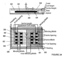
- FIG. 24 the DDP construction of Figure 23 is shown but further including a quadrature coil 62 (referred to herein as a DDPQ pad).
- a quadrature coil 62 (referred to herein as a DDPQ pad).
- the quadrature coil extends the power transfer profile when there is lateral movement of the construction shown in Figure 24 with respect to a flux generator such as the DDP pad of Figure 23 when energised by an appropriate inverter.
- the quadrature coil allows power to be extracted from the "vertical" component of the magnetic field that the receiver pad intercepts while the other coils 52, 53 facilitate power extraction from the "horizontal" component of the flux intercepted. Therefore, the construction of Figure 24 is suited as a flux receiver which may be used in a PU for the track topologies described in this document.
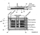
- FIG. 25 another flux receiver construction is shown which is referred to in this document as a bi-polar receiver pad or, alternatively, as a BPRP.
- the BPRP pad has a similar construction to the DDP discussed with respect to Figures 23 and 24 above.
- the BPRP pad consists, from bottom up, of an aluminium plate 57, a dielectric spacer 56, a core 54 comprising four rows of ferrite bars 55 (referred to herein as ferrites), two flat substantially coplanar, yet overlapping and ideally "rectangular" shaped coils 52, 53 (although in practice these are more oval due to the ease in winding Litz wire) spread out in the lateral direction, and a dielectric cover 58.
- the core 54 acts as a shield so that ideally all flux is channelled through the core 54 through the top of the pad.
- the plate 57 merely acts to a) eliminate and small stray or spurious fields that may be present above the core 4 in certain environments, and b) provide additional structural strength.
- the magnetic structure of the BPRP is designed so that there is substantially no mutual coupling between either of the coils 52, 53 in the primary. This allows the coils to be tuned independently at any magnitude or phase without coupling voltage into each other, which if present would oppose the power output of such a coil. Each coil can be independently tuned and regulated without affecting the flux capture and power transfer of the other coil.
- the BPRP is suited as a flux receiver which may be used in a PU for the track topologies described in this document.
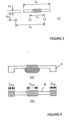
- T x The width between the forward and return conductors of each track phase loop for the construction of Figure 2 will be referred to as T x , and the amount of overlap between the two track loops is T o . It is convenient to express T o as a proportion of the total track loop width i.e. so that it varies from 0 to 1.
- T o The definition of these variables is shown graphically in Figure 3 which shows the track 1 in cross section. The values for each of these dimensions used in this example are given in Table I. It is assumed that the T x values for each phase are equal.
- the interphase mutual inductance has the effect of allowing the current flowing within one track phase to induce voltages within the other phase. This can disrupt the operating of the power supply by causing additional losses, larger bridge currents than expected and possibly charging of the DC bus in one phase.
- the topology comprises a conductor 9 which is arranged in a plane to provide a track that has a first dimension extending in a direction X with a plurality of conductor lengths 10 that are provided substantially transverse to the first dimension.
- the conductor 9 returns to the power supply 12 so the arrangement provides a bipolar track.
- conductor lengths 11 of the conductor 9 on the return path to the supply are also arranged to lie substantially transverse to the first dimension.
- the lengths 10 and 11 are grouped in pairs. The current will flow in the same direction through the lengths of each pair, so a series of alternating pole areas is provided, the pole areas being formed by the paired conductor lenghts 10 and 11, and lying transversely relative to the first direction.
- the track according to Figure 7 may form a pad, or segment, or track section, or track module (as may any of the other conductor arrangements disclosed herein) which can be provided adjacent to other pads, segments, sections or modules to form a larger track arrangement.
- Adjacent pads, segments, sections or modules can be provided extending in the first dimension or the transverse dimension, and the aspect ratio of each pad or segment may vary. For example a pad or segment may be shorter in the first dimesion than it is in the transverse dimension.
- the track topology of Figure 7 may also be used to provide a two phase track topology according to another embodiment of the invention, as shown in Figure 8 .
- the topology comprises a primary conductor arrangement of two overlaid conductors 14 and 15, each arranged as described above with reference to Figure 7 .
- the conductors 14 and 15 each return to a supply 16 and 17 respectively.
- the power supplies 16 and 17 will be each be synchronised and energised 90° out of phase with each other. Preferably they share a common DC bus to ensure any mistuning or VAR loading from the receiver (i.e. the pick-up) is managed.
- the pitch of the track, p is the distance between the transverse conductor sections, and this should be fixed so that the phases are mutually decoupled.
- the distance p will need to be varied in order to substantially mutually decouple each of the track phases from each other, and this distance p, dependant on the amount of ferrite material added, can be determined either experimentally or using a 3D magnetic modelling package. By experiment, if one of the track phases is energised, then the voltage across the terminals of the second track can be measured.
- the topology shown in Figure 8 is referred to in this document as a bipolar two phase track because the conductors are configured to explicitly return.
- the nature of the layout means that a receiver fixed to a vehicle which moves above the track is effectively exposed to forward and reverse currents that are 90°apart when defined from a fixed reference direction or first dimension. This dimension is indicated by n in Figure 8 , and n also defines one wavelength of one of the phase conductors in Figure 8 .
- the arrangement of the conductors is substantially planar and the conductors are arranged so that sections of each phase conductor are provided as lengths which extend across the plane substantially transversely relative to the first dimension, the lengths being substantially parallel to each other and spaced from each other.
- the overall length of track which can be driven is limited practically by the chosen frequency, the native inductance of each conductor and the chosen track phase current magnitude.
- the length of track can however be extended without affected the receiver by adding another two tracks with power supplies at the end of the track loop.
- Each of the phases of this second track loop should preferably be synchronised in phase with the first track.
- An example is shown in Figure 9 in which a further two phase track having phase conductors 18 and 19 which are powered by power supplies 20 and 21 has been concatenated with the track construction of Figure 8 .
- the additional track structure could instead, or additionally, be concatenated in the transverse direction rather than the first direction.
- a three phase track topology as shown in Figure 10(a) has been proposed, comprising three looped conductors 31, 32 and 33.
- a vehicle with a pick-up drives along the length of the track 30, in a direction shown in Figure 10(a) as the x-axis.
- the power supply and compensation system 34 uses an inductor-capacitor-inductor (LCL) impedance converting network, as described earlier in this specification, to convert the voltage sourced inverter into a current source suitable for driving the inductive track.
- LCL inductor-capacitor-inductor
- the leakage inductance of an isolating transformer is used as the first inductor and the track forms the last inductor, and as such only real power passes through the transformer.
- a flux cancelling approach can be used where transformer coupling is introduced at the start of the track to create coupling between phases that is out of phase with coupling between the conductors along the length due to geometry. This is implemented by appropriately looping the conductors through toroid cores at the start. Both techniques employed to minimise the effect of interphase mutual inductance result in either poor performance or added expense due to the extra magnetic components required.
- the new three phase track topology introduced in this specification and described below does not suffer from drawbacks of the previous topologies and has further advantages that enable a RPEV system to be implemented extremely cost effectively.
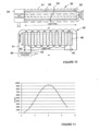
- the three phase track 40 in Figure 10(b) comprises three overlaid conductors 41, 42 and 43 that are energised by a power supply and compensation system 44 and are terminated to a wye point 45 at the end.
- the nature of the layout means that the PU is effectively exposed to forward and reverse currents, from a fixed reference, that are 60°apart and the addition of the flux from each conductor results in a travelling magnetic field along the length of the track. Given there are no explicit return conductors, the track 40 is unipolar three phase.
- the power supply uses an identical LCL impedance converting network however the outputs of the transformers are connected to the track in a wye configuration. Due to the geometry of the track, there is balanced mutual coupling between the phases, which can easily be accounted for in the LC portion of the impedance converting network, therefore it can be easily driven by the inverter. Another major advantage is that the horizontal tolerance of the PU is largely decoupled from the resonant current rating of the track and pick-up tuning capacitor, unlike the bipolar track.
- the power transfer to a PU of fixed dimensions depends on the pitch or spaces between the conductors that form the track. That is, if the pitch of a bipolar track is increased to improve horizontal tolerance, the track current must increase to maintain the same flux density (B) above the track to ensure equivalent power transfer. Higher currents result in improved power transfer but also in greater copper losses (I 2 R) in the track that reduce efficiency.
- the width determines the horizontal tolerance as shown by the shaded area in Fig. 10 (b) . Increasing tolerance by making the track wider is preferable because the added length only increases the copper loss linearly. Also, wider tracks are more efficient given the added length due to the edges is constant.
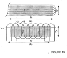
- Figures 13(a) and 13(b) Three phase track topologies according to Figures 10(a) and 10(b) are now shown in Figures 13(a) and 13(b) with labels to show the pitch of the track, p (which is the distance between conductors) along a first dimension, shown by line r in Figure 13(b) .
- the arrangement of the conductors is substantially planar and the conductors are arranged so that lengths of each phase conductor extend across the plane substantially transversely relative to the first dimension r. The lengths are substantially parallel to each other and spaced from each other.
- the time varying constructive addition of the flux from each conductor results in travelling magnetic pole pairs along the length of the track, Tx. Two of these are shown in Figure 14 , which illustrates the magnetic flux density vectors in a cut plane through section line r.
- the width of the pole varies between the track pitch and twice the track pitch however the distance from pole centre to centre remains three times the pitch.
- the unipolar track 40 has two key advantages over the bipolar design 30, namely balanced interphase coupling and improved horizontal tolerance. Due to the geometry of the track, there is equal coupling between phases and this can easily be accounted for in the LC portion of the impedance converting network.
- a 2210mm L x 890mm W section with a pitch of 65mm was built.
- the width of the track was determined by the length of the straight midsection, which was 500mm, and the pitch.
- the central section of the track was made up of 5 periods of each phase, to minimise unbalanced interphase coupling due to end effects.
- a simple 16 turn flat bar pickup measuring 168mm L x 93mm W x 16mm T was used for testing and comparison with a 3D finite element model.
- the PU consisted of 6 standard 'I' cores made from N87 material, which has a relative permeability of 2400. The spread of the PU coil was adjusted to cover 80% of the PU length.
- test track was constructed with stranded mains cable rather than Litz wire for ease of prototyping, as such the maximum current without excessive track heating was 22.5A RMS at 38.4kHz.
- V oc and I sc measurements obtained from the model created in JMAG were found to agree within 5% of those measured on average. This enables large models suitable for RPEVs to be investigated and optimised via simulation with confidence.
- a power input of 20 - 30kW to an EV is sufficient for motive power and charging while driving in various situations such as urban, highway and mountainous terrains.
- the energy collected by the EV mainly depends on the length of powered road and vehicle speed. As such, powered sections are particularly suited where average vehicle speeds are low. Additionally, the placement of powered sections on steep sections of roadway is desirable as this will limit the discharge rate of the vehicle battery and prolong its life.
- An advantage of the proposed unipolar topology, shown in Figures 10(b) and 13(b) , is that the pattern can be easily continued at either end by adding additional tracks either side. Provided the power supplies are synchronised, this interleaving enables a long portion of road to be continuously powered.
- Such a track system can be completely modular with power supplies powering fixed lengths of track in the order of 10's of metres. This creates redundancy in the system, if one section gets damaged or one power supply fails, the powered roadway will still function at close to full capacity. This approach also makes installation simpler.
- ferrite strips have been placed below the track to improve coupling and to prevent the magnetic field below the track from interfering with underground cabled.
- the profile is smoother when the PU is closer to the track, the uncompensated power is 5.75 kVA with an air gap of 200mm, indicating the system will meet the power requirements of an EV with a practical operational Q of 3-5.
- the EV will receive full power with a horizontal tolerance of 500mm, the track can be made wider should more tolerance be required.
- the drop in power as the PU is brought close to the ends on the simulated track will not occur on a roadway when multiple track sections have interleaved ends.
- Inductive Power Transfer is a suitable means for powering EVs through the road, however full scale implementation has been infeasible due to poor horizontal tolerance offered by existing IPT tracks.
- the new three phase unipolar track 40 allows significantly better horizontal tolerance than earlier published work with a small increase in cost and copper losses.
- a small scale prototype has shown that the topology provides balanced phase inductances making it easy for the supply to drive. Measured and simulated results of the prototype differed by 10% at most allowing a practical design to be created by simulating combinations of design variables such as track current, pitch, width as well as PU length and width.
- the simulated track is able to deliver 30kW that provides motive and charge power for an EV with a 200mm air gap between the PU and track, the horizontal tolerance can be tailored to the width of a roadway vehicle lane.
- this embodiment of track 40 includes magnetically permeable material which is provided in association with the track conductors.
- Elongate strips 50, 51, 52 and 53 of magnetically permeable material are provided beneath the conductors 41, 42 and 43 and so as to be magnetically associated with the conductors.
- the strips may be ferrite.
- the dimensions and spacing of the strips, together with the pitch and length/width of the conductor arrangement may be varied to provide useful flux at a desired height above the arrangement for inductive power transfer.
- the conductors 41, 43 and 43 may be laid across a roadway, or parallel with a roadway, and can provide a field which is capable of being received by pick-ups having different geometries.
- the magnetic components should be optimised.
- the following parameters affect the output power of the system: PU length, width, and thickness, track pitch and width, and the design of the ferrite structure under the track.
- the width of the track is not investigated, it can be widened if more horizontal tolerance is required.
- a simple flat bar PU is investigated and the track is optimised.
- Such a PU will only couple power when the magnetic field is horizontal, illustrated by the flux vectors in Figure 14 .
- a new PU topology, termed the quadrature, has been proposed by Elliott G.A.J., Raabe S., Covic G.A. and Boys J.T. "Multi-phase pick-ups for large lateral tolerance contactless power transfer systems", IEEE Trans. Industrial Electronics Society, 57, no 5, pp 1590-1598, May 2010 .
- This PU topology is also referred to in WO2010090539 .
- This PU contains additional coils that are able to take advantage of the vertical field component that simply adds a fixed amount of power to the EV. Therefore if a track is optimised for a simple PU, the track can be considered optimal.
- the pick-up coil arrangement may comprise two substantially flat coils in a substantially co-planar arrangement.
- the arrangement may also include a third coil which overlaps the two substantially co-planar coils.
- the pick-up coil arrangement comprises a single coil which may be a flat coil which is substantially parallel to the plane of the primary conductor arrangement, or may be wound about an axis which is arranged substantially parallel to the first dimension, r, of the primary conductor arrangement.
- the PU length should not be so small that the PU is being soley powered by only one conductor portion or length, but not so long that undesirable cancellation effects occur. Therefore, for two phase tracks a PU length that does not exceed one wavelength of a phase conductor (as indicated by n in Figure 8 ) is preferred.
- Optimal PU length for three phase topologies is discussed below.
- There are two approaches to matching the track pitch and PU length namely varying the length of the PU with a fixed pitch track or varying the pitch with a fixed PU length. Both techniques have been investigated via simulation (note the track current was 22.5A at 38.4kHz and the air gap was 60mm).
- the graph in Figure 15 shows the uncompensated power of the PU as it is made longer on a track with a pitch of 65mm. The coupling is at a maximum when the PU is four times the pitch or 260mm long. This result is consistent with the field vectors shown in Figure 14 .
- ferrite utilisation efficiency is a metric used to compare designs. It is determined by dividing the P su by the volume of ferrite. Given the width of the PU is constant, this ferrite utilisation can be compared as VA/cm of PU length. Designs that have a PU length 2.8 times the pitch have been found to offer the best coupling for a given volume of ferrite and hence PU weight.
- the PU coupling is at a maximum when the poles are positioned equidistantly from the PU ends and reaches a null when a pole is centred under a PU as shown in Figure 17 (a) and (b) .
- the poles With a track that has a relatively small pitch compared to the PU length (for example in Figure 17 (a) ), the poles are closer together resulting in more flux cancellation for a given PU length.
- Increasing the pitch, as shown in Figure 17 (b) increases the pole pitch, resulting in less cancellation because the distance to the next pole is greater.
- the fundamental flux height above the track determines how much flux will be coupled to the PU and this height is determined by the pitch of the track.
- the distance between adjacent phase conductors of the primary conductor arrangement is selected dependent on the length of a pick-up coil arrangement for receiving power from the primary conductor arrangement. In one embodiment the distance between adjacent phase conductors is substantially 0.2 to 0.5 of the dimension of the pick-up coil arrangement in the first dimension. In another embodiment the distance between adjacent phase conductors is substantially 0.25 to 0.5 of the dimension of the pick-up coil arrangement in the first dimension.
- a practical RPEV system needs to deliver 20kW with an air gap of 150-200mm. All subsequent simulations have been done with a 175mm air gap for a fair comparison.
- the track current has been increased to 250A as industrial IPT systems use currents in the range of 100-300A at -40kHz.
- a series of simulations were run to determine the effect of track pitch on uncompensated power.
- the length of the 300mm wide PU was constantly adjusted to be 4 times the track pitch.
- a solid ferrite sheet was added under the track to increase power transfer.
- the results of the simulation along with a volumetric comparison are shown in Figure 19 .
- the increase in coupled power for a track with and without ferrite is relatively linear at pitches greater than 150mm.
- a practical RPEV system that operates with an air gap of 175mm between the track and the PU has been designed based on previous simulation results.
- the total track width is 1550mm, corresponding to a midsection width of 800mm and a pitch of 250mm.
- Eight 20mm wide ferrite strips that are 16mm deep and provided 5mm below the track conductors with a relative permeability of 2000 have been placed equidistantly under the straight section of the track.
- a power profile is shown in Figure 22 which corresponds to 0.25 of the pick-up coil length. Each line represents the P su along one period of a phase at various offsets from the centre. Assuming a Q of 5 is possible, the power to the EV will be a constant 30kW over an 800mm wide zone.
- the ripple in the power profile when the PU is close to the edge of the track is due to the curved end sections, as there is slightly more coupling when the PU is above two overlapping curves than when it is over one.
- This invention provides new two and three phase track topologies. These tracks may have balanced mutual inductance between phases making them easier to drive than other designs. Another advantage is that increasing horizontal tolerance only adds linearly to copper loss and cost.
- the conductors for a two (or more) phase track according to the invention may be laid across a roadway for example, or parallel with a roadway, and can provide a field which is capable of being received by pick-ups having different geometries.
- the primary conductor arrangement may be provided in the form of a pad or module that can be conveniently placed in or on a ground or floor surface such as a roadway for example.
- the arrangement may be part of a modular primary conductive pathway system for IPT. It will also be appreciated that embodiments of the invention are applicable to roadways that may comprise paths for track-bound vehicles.
- ATV Automatically Guided Vehicle
- the primary conductor arrangements described herein may be used in conjunction with magnetically permeable materials such as the ferrite strips described with reference to figure 12(b) .
Landscapes
- Engineering & Computer Science (AREA)
- Power Engineering (AREA)
- Mechanical Engineering (AREA)
- Transportation (AREA)
- Computer Networks & Wireless Communication (AREA)
- Current-Collector Devices For Electrically Propelled Vehicles (AREA)
- Electric Propulsion And Braking For Vehicles (AREA)
- Coils Of Transformers For General Uses (AREA)
Description
- This invention relates to Inductive Power Transfer (IPT) systems. The invention has particular relevance to multiphase IPT systems.
- IPT uses a varying magnetic field to couple power across an air gap, to a load, without physical contact. The air gap is present between a primary conductor such as an elongate loop of conductive material (generally referred to in this document as a track), and one or more pick-up devices that have a secondary coil which receive power from the magnetic field associated with the track. System performance is not affected by wet or dirty environments and there are no safety risks under such conditions since the components are completely isolated. IPT is reliable and maintenance free unlike conventional plug or brush and bar contact based methods such as those used on trams and electric buses. IPT is presently used in numerous industrial applications such as materials handling and integrated circuit fabrication. The systems vary in capacity from 1W-200kW and can be used to both power and recharge robots, Automatic Guided Vehicles (AGV), electronic devices, recreational people movers, buses and Electric Vehicles (EVs). IPT systems may be divided into two distinct types: distributed systems that consist of one or more movable loads that may be placed anywhere on a track, and lumped systems that only allow power transfer at a defined location.
- Distributed systems are particularly suited to Roadway Powered EV (RPEV) applications, however practical large scale RPEV systems have so far been infeasible. This is due to the large horizontal (-700mm) tolerance and ground clearance (150-200mm) required by unguided EVs. The track topology presented in this document offers a significant improvement over previous designs by allowing increased horizontal tolerance with minimal increase to the system cost. Those skilled in the art will appreciate that this document refers to application of the invention in the context of EVs, but the invention is applicable to many other IPT system applications.
- EVs help reduce dependence on fossil fuels, emission of greenhouse gasses and emission of pollutants. Consequently, uptake of EVs has been increasing since the 1990's however market penetration has been low because EVs are not as cost effective as conventional vehicles. The present EV market is dominated by hybrid vehicles that derive their energy from a combustion engine, however, plug-in EVs (PHEV) have recently been introduced enabling energy from the grid to mitigate gasoline consumption. In order for EVs to gain widespread adoption, major improvements are required in battery life and cost, and grid connection. The latter allows opportunistic charging after each trip rather than a long charge at the end of the day. As a result battery wear is significantly reduced by minimising the depth of discharge and the EV has a lower cost since a smaller battery is required. The preferred solution, that makes EVs more cost effective than gasoline vehicles is to power and recharge the EV via the road. It should be noted that the infrastructure for such a dynamic charging system could be relatively small because travel on interstate highways makes up 1% of roadway miles but carries 22% of all vehicle miles travelled. An EV that has 50% of its driven miles connected to a dynamic charging system would be as cost effective as a conventional vehicle and does not incur additional gasoline costs.
- An IPT system comprises three main components that are shown for a single phase system in
Figure 1 . The power supply produces a sinusoidal current (typically in the 10-100 kHz frequency range for medium to high power systems) that drives a current (I1) in an inductive primary conductive path, or track. The parallel compensation capacitor C1 allows the track current, I1, to resonate, increasing the magnetic field strength in the vicinity of the track. This minimises the VA rating of the power supply for a given load. The track and secondary receiver device to which power from the track is transferred inductively act as a loosely coupled transformer enabling power transfer over relatively large air gaps. The receiver is commonly referred to as an IPT Pick-up (PU) and has an inductance, L2, which is tuned for resonance at the frequency of the current in the track using C2. This compensates for the relatively large PU leakage inductance. The voltage across C2 is rectified and a switched mode controller enables the resonant tank to operate at a defined quality factor, Q, to boost power transfer and provide a usable DC output. The power output of an IPT system (Pout ) is quantified by the open circuit voltage (Voc ) and short circuit current (Isc ) of the PU as well as the PU circuit quality factor, as shown in (1).
- Psu is the uncompensated power, ω is the angular frequency of the track current I1 , M is the mutual inductance between the track and PU. As shown in (1), the output power is dependent on the power supply (ωI1 2 ), magnetic coupling (M2 /L2 ) and PU controller (Q). Increasing the power output and separation between the track and PU is highly desirable but efficiency is limited by the operational frequency (switching loss) and current rating (copper loss) of the system. Allowing a system to operate at a high Q boosts power transfer but in practical applications it is normally designed to operate between 4 and 6 due to component VA ratings and tolerances. Due to these limits, the greatest increase in system performance can be achieved by good magnetic design.
- A laboratory 16kW prototype single phase RPEV system has been built in the past (see G. A. Covic, J. T. Boys, M. L. G. Kissin and H. G. Lu, "A Three-Phase Inductive Power Transfer System for Roadway-Powered Vehicles", Industrial Electronics, IEEE Transactions on, vol. 54, no. 6, pp. 3370-3378, 2007). The track in that system is essentially an elongated spiral winding with the longer sides placed on adjacent lanes. Consequently the PU is only exposed to flux generated by current flowing in one direction and there are no nulls in the power profile across the track as would occur with a simple PU on a conventional single phase track, where the conductors are placed side by side. The system was built before modem ferrites and power electronic components were developed, and this is reflected in its performance. The air gap between the track and PU was controlled by an electronic actuator to be 30mm and full power could be supplied up to an offset of 120mm from the track centre. The relatively low horizontal tolerance necessitated an automatic guidance system.
- A 5kW single phase system that operates with a 200mm air gap has been built and tested and is disclosed in G.A. Elliott, J.T. Boys and A.W. Green, "Magnetically coupled systems for power transfer to electric vehicles," in Proceedings International Conference on Power Electronics and Drive Systems, Singapore, 1995, pp. 797-801. However the horizontal tolerance is 60mm. Notably, the system does not use ferrite in the PU and this causes significant problems when installed in an EV. Ferrite ensures the flux remains within the PU and allows aluminium shielding to be used, this is necessary to limit losses in the steel chassis and to meet magnetic field exposure guidelines.
- One approach discussed but not employed by G. Elliott, S. Raabe, G. Covic and J. Boys, in "Multi-Phase Pick-Ups for Large Lateral Tolerance Contactless Power Transfer Systems," Industrial Electronics, IEEE Transactions on, vol. PP, no. 99, pp. 1-1, 2009 to improve the horizontal tolerance on a single phase track was to use a complicated PU that contained six offset coils. As the PU is moved horizontally across the track different sets of coils are energised thus increasing tolerance. However this approach is not suitable for high power systems due to mutual coupling between the coils that makes tuning the active coil problematic. The unused parallel tuned coils need to be shorted and doing so affects the flux path of the active coil resulting in losses.
- In order to improve horizontal tolerance, a three phase track topology as shown in Fig.2 (a) was proposed by G. A. Covic, J. T. Boys, M. L. G. Kissin and H. G. Lu, in "A Three-Phase Inductive Power Transfer System for Roadway-Powered Vehicles," Industrial Electronics, IEEE Transactions on, vol. 54, no. 6, pp. 3370-3378, 2007. The vehicle drives along the length of the track, Tx, which is referred to as the x-axis. The system uses an inductor-capacitor-inductor (LCL) impedance converting network that converts the voltage sourced inverter into a current source suitable for driving the inductive track. The leakage inductance of the isolating transformer is used as the first inductor and the track forms the last inductor, so that only real power passes through the transformer. Large reactive currents (I1 in
Figure 1 ) circulate in the track and capacitor only. Three individual isolating transformers connected in a delta-delta configuration were used for each phase, however the output terminals of the transformers were connected directly to the start and return of each track loop resulting in a six wire track. This track topology is termed "bipolar" in this document because the PU is exposed to both forward and returning currents to the supply. The overlapping nature of the track phases results in currents that differ by 60° in each adjacent wire and in a similar manner to windings in a cage induction motor, this creates a travelling field across the width (Ty) of the track. This moving field results in a wide and even power profile with a simple single coil PU. This power profile can be further improvedas discussed in "Multi-Phase Pick-Ups for Large Lateral Tolerance Contactless Power Transfer Systems," Industrial Electronics, IEEE Transactions on, vol. PP, no. 99, pp. 1-1, 2009 using a PU with quadrature coils. -
WO2010/031595 describes a track for inductively transferring energy to a vehicle. M. L. G. Kissin, J. T. Boys and G_ A. Covic "Interphase Mutual Inductive Power Transfer Systems," Industrial Electronics, IEEE Transactions on, discloses a roadway for powering electric vehicles using electromagnetic induction. - However, a consequence of having overlapping tracks is the presence of mutual inductance between phases, so that energy from one track phase couples into adjacent phases, similar to the power coupling between each track conductor and the PU. This cross coupling causes different legs in the inverter to source large currents and the DC bus voltage surges undesirably as energy is fed into the inverter.
- It is an object of the present invention to provide an IPT system, or one or more components of an IPT system (such as a primary conductor arrangement) that will either ameliorate one or more disadvantages of prior systems or arrangements, or which will at least provide the public with a useful choice.
- In one aspect the invention broadly provides a multiphase IPT primary track conductor arrangement as defined in
claim 1 comprising a first phase conductor and a second phase conductor, the phase conductors being arranged substantially in a plane and so as to overlap each other and being arranged such that there is substantially balanced mutual coupling between the phase conductors; wherein the phase conductors extend longitudinally in the plane in a first dimension and a plurality of lengths of each phase conductor extend across the plane substantially transversely relative to the first dimension, the transverse lengths being substantially parallel to each other and spaced from each other; wherein the transverse lengths of each phase conductor are grouped in pairs so that current will flow in the same direction through each pair; and wherein each phase conductor comprises a forward and return conductor to carry forward and reverse currents. - In a further aspect of the invention, a multiphase inductive power transfer system is provided as defined in
claim 7. -
-
Figure 1 is a diagram showing a known arrangement of IPT system components for a single phase track system. -
Figure 2 is a diagram of a two-phase bipolar IPT system including a single flat pick-up. -
Figure 3 is a diagram showing a cross-section through the IPT track offigure 2 . -
Figure 4(a) is a diagram of a flat-E pick-up. -
Figure 4(b) is a diagram of a flat pick-up. -
Figure 5 is a plot of measured power transfer for a the pick-up offigure 4(a) on the track offigure 2 . -
Figure 6 is a plot of measured power transfer for a the pick-up offigure 4(b) on the track offigure 2 . -
Figure 7 is a diagrammatic plan view of a bipolar single phase IPT primary conductor arrangement. -
Figure 8 is a diagrammatic plan view of the arrangement offigure 7 including another similar arrangement to provide a further phase, the phases being overlaid to provide balanced mutual coupling therebetween. -
Figure 9 is a diagrammatic plan view showing two arrangements according toFigure 8 concatenated. -
Figure 10(a) is a diagrammatic plan view of one bipolar three phase IPT track topology. -
Figure 10(b) is a diagrammatic plan view of one unipolar three phase IPT track topology. -
Figure 11 is a plot of simulated Psu against PU length normalised to a track pitch of 250mm at an air gap of 150mm. -
Figure 12(a) is a plot of simulated Psu at various vertical separations against position along a 4m long trackwith a current of 250A at 38.4kHz. -
Figure 12(b) is a perspective view of an embodiment of a track and PU used in the simulation in connection withFigure 12(a) . -
Figure 13 is a further diagram of three phase IPT track topologies (a) bipolar and (b) unipolar offigures 10(a) and 10(b) . -
Figure 14 shows magnetic flux density in cross-section through centre of a unipolar track with pole positions identified. -
Figure 15 is a graph of Normalised Psu and power per mm of ferrite for a PU -
Figure 16 is a graph of Psu for PUs of various lengths normalised to track pitch. -
Figure 17 shows magnetic flux vectors illustrating nulls with optimal PUs on tracks with small and large pitches. The fundamental flux heights are shown by h. -
Figure 18 is a graph showing the effect of PU width on Psu at an air gap of 60mm (65mm pitch) -
Figure 19 is a graph showing increasing track pitch with a matched PU -
Figure 20 is a graph showing the effect of varying the volume of track ferrite by using 5 or 10 strips of varying widths, the track is 600mm wide. -
Figure 21 is a graph showing the effect of varying the relative permeability of a solid sheet under the track. -
Figure 22 is a graph showing performance of a practical RPEV system at 175mm separation between the track and the PU. -
Figure 23 is a side view and a plan view respectively of a magnetic flux receiver pad; -
Figure 24 is a side view and plan view respectively of the pad ofFigure 23 including a quadrature coil; -
Figure 25 is a side view and plan view respectively of an alternative form of magnetic flux receiver pad; - Embodiments of the invention and examples useful for understanding the embodiments will now be described, by way of example only, with reference to the accompanying drawings.
- A two-phase bipolar IPT system is shown in
Figure 2 . Thetrack 1 consists of twoextended loops independent inverter up 3 is shown adjacent to thetrack 1. - Multiphase pickups have recently been proposed as an alternative method for increasing the tolerance of the system to lateral movement of the pickup. The simplest of these is known as the quadrature pickup, and make use of both the horizontal and vertical components of the magnetic flux generated by the IPT track, as opposed to standard flat pickups which make use of only one component. This is achieved by winding two coils on the pickup core.
- There are two ways of achieving the quadrature winding. The first is to wind the second coil physically in quadrature with the first coil, which requires the use of a flat-
E core 5, as shown inFigure 4(a) . The second option is to wind two individual coils on a standardflat core 6, one at each end, as shown in as shown inFigure 4(b) . If these coils are connected in series but 180° out of phase, they will also allow the capture of the vertically oriented flux. Regardless of which topology is chosen, each of the quadrature coils can be individually tuned, their outputs combined and the output controlled with a single switched-mode controller. - Referring to
Figure 23 , a magnetic flux pad construction previously disclosed by Boys, Covic, Huang and Budhia is shown which has excellent characteristics suitable for vehicle applications. The construction ofFigure 23 has been published in international patent publicationWO2010/090539A1 . For convenience, this general construction is referred to herein as a DDP pad. - The DDP pad shown in
Figure 23 generally comprises two substantially coplanar coils referenced 52 and 53 which are magnetically associated with and sit on top of, acore 54. The pad will in practice be inverted so that the coils face the primary track. As can be seen from theFigure 23 , thecore 54 may consist of a plurality of individual lengths of permeable material such as ferrite strips orbars 55 which are arranged parallel to each other but spaced apart. The pad construction may include aspacer 56 on which the core is located, and aplate 57 below the spacer. In some embodiments acover 58 may be provided on the other surface of theflat coils Padding 59 may be provided about the periphery of the pad. As can be seen, thecoils pole area Figure 23 may be used as a flux receiver which may be used in a PU for the track topologies described in this document. - Turning now to
Figure 24 , the DDP construction ofFigure 23 is shown but further including a quadrature coil 62 (referred to herein as a DDPQ pad). This construction is also described in patent publicationWO2010/090539A1 . The quadrature coil extends the power transfer profile when there is lateral movement of the construction shown inFigure 24 with respect to a flux generator such as the DDP pad ofFigure 23 when energised by an appropriate inverter. The quadrature coil allows power to be extracted from the "vertical" component of the magnetic field that the receiver pad intercepts while theother coils Figure 24 is suited as a flux receiver which may be used in a PU for the track topologies described in this document. - Turning now to
Figure 25 , another flux receiver construction is shown which is referred to in this document as a bi-polar receiver pad or, alternatively, as a BPRP. The BPRP pad has a similar construction to the DDP discussed with respect toFigures 23 and24 above. In one embodiment the BPRP pad consists, from bottom up, of analuminium plate 57, adielectric spacer 56, acore 54 comprising four rows of ferrite bars 55 (referred to herein as ferrites), two flat substantially coplanar, yet overlapping and ideally "rectangular" shaped coils 52, 53 (although in practice these are more oval due to the ease in winding Litz wire) spread out in the lateral direction, and adielectric cover 58. The core 54 acts as a shield so that ideally all flux is channelled through the core 54 through the top of the pad. Theplate 57 merely acts to a) eliminate and small stray or spurious fields that may be present above thecore 4 in certain environments, and b) provide additional structural strength. - The magnetic structure of the BPRP is designed so that there is substantially no mutual coupling between either of the
coils - The width between the forward and return conductors of each track phase loop for the construction of
Figure 2 will be referred to as Tx , and the amount of overlap between the two track loops is To. It is convenient to express To as a proportion of the total track loop width i.e. so that it varies from 0 to 1. The definition of these variables is shown graphically inFigure 3 which shows thetrack 1 in cross section. The values for each of these dimensions used in this example are given in Table I. It is assumed that the Tx values for each phase are equal. - The ideal multiphase track layout for power transfer to a standard tangential-flux flat pickup arises when the cables are equally spaced across the width of the track, giving a value of To = 0.5 as shown in
Figure 3 . This provides high power transfer and a minimum of variation across the track width. However, when the cables are spaced equally there is a mutual inductance which exists between the two loops.TABLE I TWO-PHASE IPT TRACK DETAILS TX 120mm TO 0.29 I 80A RMS f 0 20 kHz TABLE II Flat Pickup Dimensions PX 118mm PY 20mm PZ 210mm DY 30mm CHX 70mm CVX 20mm TABLE III Flat-E Pickup Dimensions PX 145mm PY 20mm PZ 200mm DY 30mm - The interphase mutual inductance has the effect of allowing the current flowing within one track phase to
induce voltages within the other phase. This can disrupt the operating of the power supply by causing additional losses, larger bridge currents than expected and possibly charging of the DC bus in one phase. - It is possible to produce a track layout that eliminates the interphase mutual inductance by changing the amount of overlap between the two track phases to To = 0.29, instead of the optimal 0.5. However, unless a quadrature pickup is used, this results in a substantial degradation of the magnetic field created by the track and thus poorer power transfer to a flat pickup.
- A single two-phase IPT track system was created for the purposes of measurements, with the characteristics given in Table I. Two quadrature pickups were also created; a standard flat type, and a flat-E type. These have the physical dimensions given in Tables II and III, respectively.
- Since no optimization of the open-circuit voltages generated by the pickups has been attempted, this section will present only the uncompensated power transferred from the track to each of these pickups. This gives a good indication of the performance of each of the pickup configurations, although it is noted that a smoother output is possible if the coil outputs are balanced.
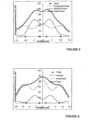
- Measured results of the power transfer from the two-phase track to the flat-E quadrature pickup are shown in
Figure 5 . Note that the power transfer to the vertical-flux coil has a trough in the centre of the track. This is compensated by the power transfer to the horizontal-flux coil, which has a peak in the centre of the track. Similar results are obtained for the flat quadrature pickup, and are shown inFigure 6 . - A track topology according to an example is shown in
Figure 7 . Referring toFigure 7 , the topology comprises aconductor 9 which is arranged in a plane to provide a track that has a first dimension extending in a direction X with a plurality ofconductor lengths 10 that are provided substantially transverse to the first dimension. Theconductor 9 returns to thepower supply 12 so the arrangement provides a bipolar track. In particular,conductor lengths 11 of theconductor 9 on the return path to the supply are also arranged to lie substantially transverse to the first dimension. Thus thelengths conductor lenghts - The track according to
Figure 7 may form a pad, or segment, or track section, or track module (as may any of the other conductor arrangements disclosed herein) which can be provided adjacent to other pads, segments, sections or modules to form a larger track arrangement. Adjacent pads, segments, sections or modules can be provided extending in the first dimension or the transverse dimension, and the aspect ratio of each pad or segment may vary. For example a pad or segment may be shorter in the first dimesion than it is in the transverse dimension. - The track topology of
Figure 7 may also be used to provide a two phase track topology according to another embodiment of the invention, as shown inFigure 8 . Turning toFigure 8 , the topology comprises a primary conductor arrangement of two overlaidconductors Figure 7 . Theconductors supply WO2011/016737 , if ferrite is used underneath the track to enhance the coupling to a receiver, the distance p will need to be varied in order to substantially mutually decouple each of the track phases from each other, and this distance p, dependant on the amount of ferrite material added, can be determined either experimentally or using a 3D magnetic modelling package. By experiment, if one of the track phases is energised, then the voltage across the terminals of the second track can be measured. If the value of p is varied the measured voltage will change, and the point at which this is minimised (preferably zero) is the best choice for p. The topology shown inFigure 8 is referred to in this document as a bipolar two phase track because the conductors are configured to explicitly return. The nature of the layout means that a receiver fixed to a vehicle which moves above the track is effectively exposed to forward and reverse currents that are 90°apart when defined from a fixed reference direction or first dimension. This dimension is indicated by n inFigure 8 , and n also defines one wavelength of one of the phase conductors inFigure 8 . The arrangement of the conductors is substantially planar and the conductors are arranged so that sections of each phase conductor are provided as lengths which extend across the plane substantially transversely relative to the first dimension, the lengths being substantially parallel to each other and spaced from each other. - The overall length of track which can be driven is limited practically by the chosen frequency, the native inductance of each conductor and the chosen track phase current magnitude. The length of track can however be extended without affected the receiver by adding another two tracks with power supplies at the end of the track loop. Each of the phases of this second track loop should preferably be synchronised in phase with the first track. An example is shown in
Figure 9 in which a further two phase track havingphase conductors power supplies Figure 8 . As mentioned above, the additional track structure could instead, or additionally, be concatenated in the transverse direction rather than the first direction. - As a means to further improve horizontal tolerance, a three phase track topology as shown in
Figure 10(a) has been proposed, comprising three loopedconductors track 30, in a direction shown inFigure 10(a) as the x-axis. The power supply andcompensation system 34 uses an inductor-capacitor-inductor (LCL) impedance converting network, as described earlier in this specification, to convert the voltage sourced inverter into a current source suitable for driving the inductive track. The leakage inductance of an isolating transformer is used as the first inductor and the track forms the last inductor, and as such only real power passes through the transformer. The large reactive currents circulate in the track and capacitor only. Three individual isolating transformers connected in a delta-delta configuration were used for each phase, however the output terminals of the transformers were connected directly to the start and return of each track loop resulting in a six wire track. This track topology is termed bipolar because the PU is exposed to forward and returning currents. The overlapping nature of theconductors area 35 inFigure 10(a) shows the extent of the full power charging region provided by the track. Shadedarea 35 does not cover the outer conductors because the power transfer drops significantly before the edges of the track. - A consequence of having overlapping conductors is the presence of mutual inductance between phases, as a result energy from one phase conductor couples into adjacent conductors similarly to power coupling to the PU. This causes different legs in the inverter to source large currents due to the uneven load sharing and the DC bus voltage also rises as energy is fed into the inverter. Two approaches were shown to solve the mutual inductance problem, firstly the area of overlap between the conductor loops can be changed to reduce the mutual inductance however this results in non-uniform conductor spacing that affects the smoothness of the power profile across the width of the track. Secondly, a flux cancelling approach can be used where transformer coupling is introduced at the start of the track to create coupling between phases that is out of phase with coupling between the conductors along the length due to geometry. This is implemented by appropriately looping the conductors through toroid cores at the start. Both techniques employed to minimise the effect of interphase mutual inductance result in either poor performance or added expense due to the extra magnetic components required.
- The new three phase track topology introduced in this specification and described below does not suffer from drawbacks of the previous topologies and has further advantages that enable a RPEV system to be implemented extremely cost effectively. The three
phase track 40 inFigure 10(b) comprises three overlaidconductors compensation system 44 and are terminated to awye point 45 at the end. Although there are three conductors, the nature of the layout means that the PU is effectively exposed to forward and reverse currents, from a fixed reference, that are 60°apart and the addition of the flux from each conductor results in a travelling magnetic field along the length of the track. Given there are no explicit return conductors, thetrack 40 is unipolar three phase. The power supply uses an identical LCL impedance converting network however the outputs of the transformers are connected to the track in a wye configuration. Due to the geometry of the track, there is balanced mutual coupling between the phases, which can easily be accounted for in the LC portion of the impedance converting network, therefore it can be easily driven by the inverter. Another major advantage is that the horizontal tolerance of the PU is largely decoupled from the resonant current rating of the track and pick-up tuning capacitor, unlike the bipolar track. - The power transfer to a PU of fixed dimensions depends on the pitch or spaces between the conductors that form the track. That is, if the pitch of a bipolar track is increased to improve horizontal tolerance, the track current must increase to maintain the same flux density (B) above the track to ensure equivalent power transfer. Higher currents result in improved power transfer but also in greater copper losses (I2R) in the track that reduce efficiency. However, in the proposed unipolar track, the width determines the horizontal tolerance as shown by the shaded area in
Fig. 10 (b) . Increasing tolerance by making the track wider is preferable because the added length only increases the copper loss linearly. Also, wider tracks are more efficient given the added length due to the edges is constant. It appears that the length of track required for a given length of unipolar track is greater than that of a bipolar track but that is not the case when the areas of full power transfer are compared. The shadedarea 46 inFigure 10(b) shows the extent of the full power charging region provided by the track. The edges of theunipolar track 40 were made circular to simplify the simulation model however straight edges can be used in practice to reduce the wire length. - Three phase track topologies according to
Figures 10(a) and 10(b) are now shown inFigures 13(a) and 13(b) with labels to show the pitch of the track, p (which is the distance between conductors) along a first dimension, shown by line r inFigure 13(b) . In theunipolar track 40, the arrangement of the conductors is substantially planar and the conductors are arranged so that lengths of each phase conductor extend across the plane substantially transversely relative to the first dimension r. The lengths are substantially parallel to each other and spaced from each other. - The time varying constructive addition of the flux from each conductor results in travelling magnetic pole pairs along the length of the track, Tx. Two of these are shown in
Figure 14 , which illustrates the magnetic flux density vectors in a cut plane through section line r. The width of the pole varies between the track pitch and twice the track pitch however the distance from pole centre to centre remains three times the pitch. Theunipolar track 40 has two key advantages over thebipolar design 30, namely balanced interphase coupling and improved horizontal tolerance. Due to the geometry of the track, there is equal coupling between phases and this can easily be accounted for in the LC portion of the impedance converting network. An example of favourable balanced coupling is when energy is coupled to phase B from A at a given position along the track, because the directions of A and B change along the length of the track with respect to a fixed reference, this results in energy coupling to phase A from B and there is no net energy transfer. The power supply used for this track is identical to that of the bipolar track described in M. L. G. Kissin, J. T. Boys and G. A. Covic, "Interphase Mutual Inductance in Polyphase Inductive Power Transfer Systems," Industrial Electronics, IEEE Transactions on, vol. 56, no. 7, pp. 2393-2400, 2009, however the outputs of the transformers are connected to the track in a wye configuration. - To test the concept of a unipolar track topology, a 2210mm L x 890mm W section with a pitch of 65mm was built. The width of the track was determined by the length of the straight midsection, which was 500mm, and the pitch. The central section of the track was made up of 5 periods of each phase, to minimise unbalanced interphase coupling due to end effects. A simple 16 turn flat bar pickup measuring 168mm L x 93mm W x 16mm T was used for testing and comparison with a 3D finite element model. The PU consisted of 6 standard 'I' cores made from N87 material, which has a relative permeability of 2400. The spread of the PU coil was adjusted to cover 80% of the PU length. The test track was constructed with stranded mains cable rather than Litz wire for ease of prototyping, as such the maximum current without excessive track heating was 22.5A RMS at 38.4kHz. The Voc and Isc measurements obtained from the model created in JMAG were found to agree within 5% of those measured on average. This enables large models suitable for RPEVs to be investigated and optimised via simulation with confidence.
- A power input of 20 - 30kW to an EV is sufficient for motive power and charging while driving in various situations such as urban, highway and mountainous terrains. The energy collected by the EV mainly depends on the length of powered road and vehicle speed. As such, powered sections are particularly suited where average vehicle speeds are low. Additionally, the placement of powered sections on steep sections of roadway is desirable as this will limit the discharge rate of the vehicle battery and prolong its life.
- An advantage of the proposed unipolar topology, shown in
Figures 10(b) and13(b) , is that the pattern can be easily continued at either end by adding additional tracks either side. Provided the power supplies are synchronised, this interleaving enables a long portion of road to be continuously powered. Such a track system can be completely modular with power supplies powering fixed lengths of track in the order of 10's of metres. This creates redundancy in the system, if one section gets damaged or one power supply fails, the powered roadway will still function at close to full capacity. This approach also makes installation simpler. - Several "round robin" simulations were done to establish the relationship between the pitch of the track, PU length, track current and separation between the track and PU. In this work the most simple PU is proposed (a flat ferrite bar). For a fixed current, power increases as the pitch of the track and size of the PU is increased, however excessively large PUs have large a self inductance that limits coupling. It was decided that a track pitch of 250mm with a current of 250A would meet the requirements of an EV. The simulation results and model for an RPEV system are shown in
Fig. 12 (a) and (b) respectively, thePU 54 is swept along the length of the track. In this work ferrite strips have been placed below the track to improve coupling and to prevent the magnetic field below the track from interfering with underground cabled. The profile is smoother when the PU is closer to the track, the uncompensated power is 5.75 kVA with an air gap of 200mm, indicating the system will meet the power requirements of an EV with a practical operational Q of 3-5. The EV will receive full power with a horizontal tolerance of 500mm, the track can be made wider should more tolerance be required. The drop in power as the PU is brought close to the ends on the simulated track will not occur on a roadway when multiple track sections have interleaved ends. - Inductive Power Transfer is a suitable means for powering EVs through the road, however full scale implementation has been infeasible due to poor horizontal tolerance offered by existing IPT tracks. The new three phase
unipolar track 40 allows significantly better horizontal tolerance than earlier published work with a small increase in cost and copper losses. A small scale prototype has shown that the topology provides balanced phase inductances making it easy for the supply to drive. Measured and simulated results of the prototype differed by 10% at most allowing a practical design to be created by simulating combinations of design variables such as track current, pitch, width as well as PU length and width. The simulated track is able to deliver 30kW that provides motive and charge power for an EV with a 200mm air gap between the PU and track, the horizontal tolerance can be tailored to the width of a roadway vehicle lane. - As can be seen from
Figure 12(b) , this embodiment oftrack 40 includes magnetically permeable material which is provided in association with the track conductors. Elongate strips 50, 51, 52 and 53 of magnetically permeable material are provided beneath theconductors conductors - To ensure an RPEV system is as cost effective and efficient as possible, the magnetic components should be optimised. The following parameters affect the output power of the system: PU length, width, and thickness, track pitch and width, and the design of the ferrite structure under the track. The width of the track is not investigated, it can be widened if more horizontal tolerance is required. There are numerous PU topologies. however, considering each type is exhaustive and not necessary. Coupling between the track and PU is due to mutual inductance and this is proportional to the area intersected by flux generated by both magnetic components. Consequently, PU topologies that have small areas or volumes are fundamentally not suited to high power large air gap applications where large horizontal tolerance is needed. Here, a simple flat bar PU is investigated and the track is optimised. Such a PU will only couple power when the magnetic field is horizontal, illustrated by the flux vectors in
Figure 14 . A new PU topology, termed the quadrature, has been proposed by Elliott G.A.J., Raabe S., Covic G.A. and Boys J.T. "Multi-phase pick-ups for large lateral tolerance contactless power transfer systems", IEEE Trans. Industrial Electronics Society, 57, no 5, pp 1590-1598, May 2010. This PU topology is also referred to inWO2010090539 . This PU contains additional coils that are able to take advantage of the vertical field component that simply adds a fixed amount of power to the EV. Therefore if a track is optimised for a simple PU, the track can be considered optimal. It will be appreciated that any of the PU embodiments referred to herein may be used in combination with any of the primary track conductor arrangements referred to herein. The approach discussed below is to ensure the PU length is matched to the track. Following that, ferrite is added under the track to improve performance. Therefore, in one embodiment the pick-up coil arrangement may comprise two substantially flat coils in a substantially co-planar arrangement. The arrangement may also include a third coil which overlaps the two substantially co-planar coils. In another embodiment the pick-up coil arrangement comprises a single coil which may be a flat coil which is substantially parallel to the plane of the primary conductor arrangement, or may be wound about an axis which is arranged substantially parallel to the first dimension, r, of the primary conductor arrangement. - In relation to two phase track topologies the PU length should not be so small that the PU is being soley powered by only one conductor portion or length, but not so long that undesirable cancellation effects occur. Therefore, for two phase tracks a PU length that does not exceed one wavelength of a phase conductor (as indicated by n in
Figure 8 ) is preferred. - Optimal PU length for three phase topologies is discussed below. There are two approaches to matching the track pitch and PU length, namely varying the length of the PU with a fixed pitch track or varying the pitch with a fixed PU length. Both techniques have been investigated via simulation (note the track current was 22.5A at 38.4kHz and the air gap was 60mm). The graph in
Figure 15 shows the uncompensated power of the PU as it is made longer on a track with a pitch of 65mm. The coupling is at a maximum when the PU is four times the pitch or 260mm long. This result is consistent with the field vectors shown inFigure 14 . The pole pitch is three times that of the track and with 80% of the ferrite covered, almost all of the available horizontal flux is captured resulting in maximum coupling. Increasing the PU and hence coil length is undesirable as the direction of the horizontal field changes to oppose the flux in the centre of the PU ferrite. In this work, ferrite utilisation efficiency is a metric used to compare designs. It is determined by dividing the Psu by the volume of ferrite. Given the width of the PU is constant, this ferrite utilisation can be compared as VA/cm of PU length. Designs that have a PU length 2.8 times the pitch have been found to offer the best coupling for a given volume of ferrite and hence PU weight. - The effect of increasing the track pitch for PUs of various lengths is shown in
Figure 16 where the PU lengths have been normalised to the track pitch. The peak in coupled power occurs at PU lengths 2.2 to 2.4 times the track pitch. Clearly, larger PUs and larger pitches permit more power transfer, however this result appears to conflict with the previous simulation results inFigure 15 . The power output of a 260mm long PU on a 120mm pitch track is almost double that of the same PU on a 65mm pitch track. The difference in coupling is due to flux cancellation and the fundamental flux path height above the track. A track that has a pitch of 65mm has almost two poles for an optimal length PU. Therefore this PU will experience more flux cancellation than it would on a track with a 120mm pitch. The PU coupling is at a maximum when the poles are positioned equidistantly from the PU ends and reaches a null when a pole is centred under a PU as shown inFigure 17 (a) and (b) . With a track that has a relatively small pitch compared to the PU length (for example inFigure 17 (a) ), the poles are closer together resulting in more flux cancellation for a given PU length. Increasing the pitch, as shown inFigure 17 (b) , increases the pole pitch, resulting in less cancellation because the distance to the next pole is greater. The fundamental flux height above the track determines how much flux will be coupled to the PU and this height is determined by the pitch of the track. Having a low pitch means the height of the flux path above the track is limited and this is approximated by h inFigure 17 (a) . Note the height is shown under the track for convenience, in practice the flux about a track without ferrite is symmetrical. Doubling the pitch doubles the flux path height, as indicated inFigure 17 (b) . This allows significantly improved power output for a given track current and volume of PU ferrite. Therefore, in one embodiment the distance between adjacent phase conductors of the primary conductor arrangement is selected dependent on the length of a pick-up coil arrangement for receiving power from the primary conductor arrangement. In one embodiment the distance between adjacent phase conductors is substantially 0.2 to 0.5 of the dimension of the pick-up coil arrangement in the first dimension. In another embodiment the distance between adjacent phase conductors is substantially 0.25 to 0.5 of the dimension of the pick-up coil arrangement in the first dimension. - The results of a simulation where the width of the PU was varied from 10mm to 300mm under the same conditions are shown in
Figure 18 . The increase in Psu as the PU is made wider is reasonably linear however the volumetric efficiency decreases. This is partly due to the end effect and the finite width of the track. Flux from sections of wire not directly under the PU will get attracted to the ferrite and pass through the coil. As the PU is made wider and approaches the track width, the contribution diminishes. The end effect is responsible for the initial large negative gradient of the VA per unit of ferrite volume curve. The outer edges of the front and back of the PU attract a fixed amount of flux that contributes to the total Psu. Very narrow PUs have this additional flux component as well as the component due to the width of the PU resulting in a high power per unit volume. - A practical RPEV system needs to deliver 20kW with an air gap of 150-200mm. All subsequent simulations have been done with a 175mm air gap for a fair comparison. The track current has been increased to 250A as industrial IPT systems use currents in the range of 100-300A at -40kHz. A series of simulations were run to determine the effect of track pitch on uncompensated power. The length of the 300mm wide PU was constantly adjusted to be 4 times the track pitch. A solid ferrite sheet was added under the track to increase power transfer. The results of the simulation along with a volumetric comparison are shown in
Figure 19 . The increase in coupled power for a track with and without ferrite is relatively linear at pitches greater than 150mm. Based on these results a track pitch of 250mm and width of 1350mm has been chosen for subsequent simulations. The Psu at a 250mm pitch is 11kVA and with a Q between 2 to 3, the power output is 20-30kW, which should be sufficient for an RPEV. - The cost efficiency of placing a solid sheet of ferrite under the track can be significant and adds significantly to the primary inductance. Simulations were done to determine the effect of placing continuous ferrite strips along the length of the track. The material used was N87 with a relative permeability of 2400. The results are shown in
Figure 20 (dimension in millimetres). There are two families of curves, one for Psu and the other for a volumetric comparison based on the track ferrite volume. The intersection with the y-axis is for a track without ferrite, each curve with markers is for tracks with 5 or 10 ferrite strips and the list of numbers maps to the data points. The strips are approximately 16mm thick. - The practicality of constructing a track with embedded strips may be difficult, therefore a simulation was done where the relative permeability of a solid slab under the track was varied from unity to 3000. The conditions are the same as for the previous simulation. The results are shown in
Figure 21 , as expected, the Psu is 11 kVA when the permeability is 2400. This curve can be used to match track ferrite designs with the results inFigure 20 . For example, the same performance is achieved with 10 evenly spaced 20mm wide strips or with a solid sheet of material with a relative permeability of 400. As such, it may be also possible to use ferrite powder to simplify track construction. - A practical RPEV system that operates with an air gap of 175mm between the track and the PU has been designed based on previous simulation results. The total track width is 1550mm, corresponding to a midsection width of 800mm and a pitch of 250mm. Eight 20mm wide ferrite strips that are 16mm deep and provided 5mm below the track conductors with a relative permeability of 2000 have been placed equidistantly under the straight section of the track. A power profile is shown in
Figure 22 which corresponds to 0.25 of the pick-up coil length. Each line represents the Psu along one period of a phase at various offsets from the centre. Assuming a Q of 5 is possible, the power to the EV will be a constant 30kW over an 800mm wide zone. The ripple in the power profile when the PU is close to the edge of the track is due to the curved end sections, as there is slightly more coupling when the PU is above two overlapping curves than when it is over one. - This invention provides new two and three phase track topologies. These tracks may have balanced mutual inductance between phases making them easier to drive than other designs. Another advantage is that increasing horizontal tolerance only adds linearly to copper loss and cost.
- It will be seen that the conductors for a two (or more) phase track according to the invention may be laid across a roadway for example, or parallel with a roadway, and can provide a field which is capable of being received by pick-ups having different geometries. Thus the primary conductor arrangement may be provided in the form of a pad or module that can be conveniently placed in or on a ground or floor surface such as a roadway for example. In one embodiment the arrangement may be part of a modular primary conductive pathway system for IPT. It will also be appreciated that embodiments of the invention are applicable to roadways that may comprise paths for track-bound vehicles.
- Furthermore, although examples of use in conjunction with a roadway are provided, the invention is also applicable to other applications, for example Automatically Guided Vehicles (AGVs). Also, the primary conductor arrangements described herein may be used in conjunction with magnetically permeable materials such as the ferrite strips described with reference to
figure 12(b) . - Unless the context clearly requires otherwise, throughout the description, the words "comprise", "comprising", and the like, are to be construed in an inclusive sense as opposed to an exclusive or exhaustive sense, that is to say, in the sense of "including, but not limited to".
- Reference to any prior art in this specification is not, and should not be taken as, an acknowledgement or any form of suggestion that that prior art forms part of the common general knowledge in the field of endeavour in any country in the world.
Claims (12)
- A multiphase inductive power transfer, IPT, primary track conductor arrangement comprising a first phase conductor (9, 14) and a second phase conductor (15), the phase conductors being arranged substantially in a plane and so as to overlap each other and being arranged such that there is substantially balanced mutual coupling between the phase conductors;
wherein the phase conductors (9, 14, 15) extend longitudinally in the plane in a first dimension and a plurality of lengths (10, 11) of each phase conductor extend across the plane substantially transversely relative to the first dimension, the transverse lengths (10, 11) being substantially parallel to each other and spaced from each other; characterized in that:the transverse lengths (10, 11) of each phase conductor are grouped ir pairs so that current will flow in the same direction through each pair; andeach phase conductor (9, 14, 15) comprises a forward and return conductor to carry forward and reverse currents. - A multiphase IPT primary track conductor arrangement as claimed in claim 1 wherein the relative directions of current flow in the pairs of transverse lengths alternate along the first dimension of the conductor arrangement such that energisation of the phases results in substantially no net energy transfer between phases.
- A multiphase IPT primary track conductor arrangement as claimed in any one of the preceding claims wherein the arrangement is associated with a magnetically permeable member.
- A multiphase IPT primary track conductor arrangement as claimed in claim 3, wherein the phase conductors (9, 14, 15) are provided on only one side of the magnetically permeable member.
- A multiphase IPT primary track conductor arrangement as claimed in claim 4 wherein the magnetically permeable member comprises a plurality of ferrite strips, optionally wherein the strips are elongate and spaced from each other.
- A multiphase IPT primary track conductor arrangement as claimed in any one of the preceding claims wherein the primary conductor arrangement comprises a pad, module or track segment.
- A multiphase inductive power transfer, IPT, system including a multiphase primary track conductor arrangement as claimed in any one of claims 1 to 6 and a pick-up coil apparatus for receiving power from the primary conductor arrangement.
- A multiphase inductive power transfer, IPT, system as claimed in claim 7, wherein the pick-up coil apparatus comprises two substantially flat coils in a substantially co-planar arrangement.
- A multiphase IPT system as claimed in claim 8 wherein the pick-up coil apparatus comprises a third coil which overlaps the two substantially co-planar coils.
- A multiphase IPT system as claimed in claim 7 wherein the pick-up coil apparatus comprises a single coil.
- A multiphase IPT system as claimed in any one of claims 7 to 10, wherein the distance between adjacent phase conductors is selected dependent on a length of a said coil of the pick-up coil apparatus in the first dimension, the pick-up coil apparatus being suitable for receiving power from the primary conductor arrangement.
- A multiphase IPT system as claimed in claim 11 wherein the distance between adjacent phase conductors is substantially 0.2 to 0.5 of the dimension of the coil of the pick-up coil apparatus in the first dimension.
Applications Claiming Priority (3)
| Application Number | Priority Date | Filing Date | Title |
|---|---|---|---|
| NZ58548310A NZ585483A (en) | 2010-05-19 | 2010-05-19 | Inductive power transfer system with a primary track arrangement with first and second phase conductors with balanced mutal coupling between the conductors |
| NZ58756710 | 2010-08-25 | ||
| PCT/NZ2011/000079 WO2011145953A1 (en) | 2010-05-19 | 2011-05-19 | Inductive power transfer system primary track topologies |
Publications (3)
| Publication Number | Publication Date |
|---|---|
| EP2572363A1 EP2572363A1 (en) | 2013-03-27 |
| EP2572363A4 EP2572363A4 (en) | 2017-09-27 |
| EP2572363B1 true EP2572363B1 (en) | 2024-03-20 |
Family
ID=44991882
Family Applications (1)
| Application Number | Title | Priority Date | Filing Date |
|---|---|---|---|
| EP11783803.7A Active EP2572363B1 (en) | 2010-05-19 | 2011-05-19 | Inductive power transfer system primary track topologies |
Country Status (5)
| Country | Link |
|---|---|
| US (1) | US10600564B2 (en) |
| EP (1) | EP2572363B1 (en) |
| JP (1) | JP6144195B2 (en) |
| CN (2) | CN106953368B (en) |
| WO (1) | WO2011145953A1 (en) |
Families Citing this family (49)
| Publication number | Priority date | Publication date | Assignee | Title |
|---|---|---|---|---|
| KR101825627B1 (en) * | 2010-08-06 | 2018-03-22 | 오클랜드 유니서비시즈 리미티드 | Inductive power receiver apparatus |
| GB2491651A (en) | 2011-06-10 | 2012-12-12 | Bombardier Transp Gmbh | System and Method for Transferring Electric Energy to a Vehicle Using Constant Current Operation of Segments of a Conductor Arrangement at resonance frequency |
| GB2491652A (en) | 2011-06-10 | 2012-12-12 | Bombardier Transp Gmbh | System and Method for Transferring Electric Energy to a Vehicle Using a Plurality of Segments of a Conductor Arrangement |
| JP6060158B2 (en) * | 2011-07-19 | 2017-01-11 | オークランド ユニサービシズ リミテッドAuckland Uniservices Limited | Multi-conductor single-phase induction feed truck |
| WO2014007656A1 (en) * | 2012-02-02 | 2014-01-09 | Auckland Uniservices Limited | Var control for inductive power transfer systems |
| EP2815484B1 (en) * | 2012-02-16 | 2022-11-30 | Auckland UniServices Limited | Multiple coil flux pad |
| EP2912744B1 (en) | 2012-10-29 | 2018-09-19 | Apple Inc. | A receiver for an inductive power transfer system and a method for controlling the receiver |
| JP5718879B2 (en) * | 2012-10-31 | 2015-05-13 | トヨタ自動車株式会社 | Vehicle parking assist device |
| WO2014166942A2 (en) * | 2013-04-09 | 2014-10-16 | Bombardier Transportation Gmbh | Inductive power transfer pad and system for inductive power transfer |
| EP3044494A1 (en) * | 2013-09-13 | 2016-07-20 | Biofilm IP, LLC | Magneto-cryogenic valves, systems and methods for modulating flow in a conduit |
| JP6167823B2 (en) * | 2013-10-03 | 2017-07-26 | 日産自動車株式会社 | Non-contact power feeding device |
| CN104578439B (en) * | 2013-10-21 | 2018-10-09 | 台达电子企业管理(上海)有限公司 | Device for wireless charging link |
| KR102196896B1 (en) * | 2013-11-13 | 2020-12-31 | 애플 인크. | Transmitter for inductive power transfer systems |
| US9153998B2 (en) | 2013-12-02 | 2015-10-06 | Qualcomm Incorporated | Wireless power orthogonal polarization antenna array |
| JP6770669B2 (en) * | 2014-02-21 | 2020-10-21 | オークランド ユニサービシズ リミテッドAuckland Uniservices Limited | Multi-level transducer |
| EP3146542A4 (en) | 2014-05-19 | 2017-06-14 | PowerbyProxi Limited | Magnetically permeable core and inductive power transfer coil arrangement |
| DE102014109944A1 (en) | 2014-07-16 | 2016-01-21 | Paul Vahle Gmbh & Co. Kg | Inductive energy transfer system with multi-phase primary circuit |
| WO2016024869A1 (en) | 2014-08-12 | 2016-02-18 | Powerbyproxi Limited | System and method for power transfer |
| US9780572B2 (en) | 2014-10-27 | 2017-10-03 | Qualcomm Incorporated | Wireless power multi-coil mutual induction cancellation methods and apparatus |
| WO2016072865A1 (en) | 2014-11-05 | 2016-05-12 | Powerbyproxi Limited | An inductive power receiver |
| DE102014116901A1 (en) | 2014-11-19 | 2016-06-02 | Paul Vahle Gmbh & Co. Kg | Winding arrangement for an inductive energy transmission system |
| US20160164332A1 (en) * | 2014-12-04 | 2016-06-09 | Intel Corporation | Tiled wireless charging coil solution for extended active area |
| US9698608B2 (en) * | 2014-12-29 | 2017-07-04 | Qualcomm Incorporated | System and method for multi-coil dual backbone dynamic inductive power transfer |
| WO2016167667A1 (en) * | 2015-04-17 | 2016-10-20 | 3I Innovation Limited | Inductive power transfer apparatus with improved coupling |
| DE102015005871B4 (en) * | 2015-05-11 | 2024-05-08 | Sew-Eurodrive Gmbh & Co Kg | System for contactless energy transmission from a primary conductor laid on the ground to a vehicle that can be moved on the ground |
| GB2539885A (en) * | 2015-06-26 | 2017-01-04 | Bombardier Transp Gmbh | A primary-sided and a secondary-sided arrangement of winding structures, a system for inductive power transfer and a method for inductively supplying power |
| EP3474302B1 (en) * | 2015-06-26 | 2023-04-05 | Bombardier Primove GmbH | A secondary-sided arrangement of winding structures, a system for inductive power transfer and a method for inductively supplying power to a vehicle |
| CN108141063B (en) * | 2015-08-06 | 2022-06-28 | 奥克兰大学服务有限公司 | Hybrid inductive power transfer system |
| JP6622523B2 (en) * | 2015-09-04 | 2019-12-18 | キヤノン株式会社 | Mobile device and non-contact power transmission system |
| GB2542432A (en) | 2015-09-21 | 2017-03-22 | Bombardier Transp Gmbh | Inductively transferring electric energy to a vehicle using consecutive segments which are operated at the same time |
| WO2017204663A1 (en) | 2016-05-25 | 2017-11-30 | Powerbyproxi Limited | A coil arrangement |
| WO2017209630A1 (en) | 2016-06-01 | 2017-12-07 | Powerbyproxi Limited | A powered joint with wireless transfer |
| US10355532B2 (en) | 2016-11-02 | 2019-07-16 | Apple Inc. | Inductive power transfer |
| US10447090B1 (en) | 2016-11-17 | 2019-10-15 | Apple Inc. | Inductive power receiver |
| CN206834025U (en) | 2016-11-18 | 2018-01-02 | 鲍尔拜普罗克西有限公司 | Induction type power transmission line coil assembly |
| US10978911B2 (en) | 2016-12-19 | 2021-04-13 | Apple Inc. | Inductive power transfer system |
| CN106981931B (en) * | 2017-05-17 | 2020-01-14 | 中国科学院电工研究所 | Non-contact induction power supply device of primary coil of three-phase structure |
| DE102017111256A1 (en) * | 2017-05-23 | 2018-11-29 | Paul Vahle Gmbh & Co. Kg | Inductive energy transmission system |
| CN107872081B (en) * | 2017-09-27 | 2021-04-13 | 浙江大学宁波理工学院 | Dynamic wireless charging method for robot |
| WO2019108071A1 (en) | 2017-12-01 | 2019-06-06 | Auckland Uniservices Limited | A misalignment tolerant hybrid wireless power transfer system |
| CN108382246B (en) * | 2018-03-20 | 2020-12-01 | 哈尔滨工业大学 | Three-phase magnetic coupling mechanism applied to dynamic wireless power supply of vehicle |
| US10593468B2 (en) | 2018-04-05 | 2020-03-17 | Apple Inc. | Inductive power transfer assembly |
| CN108683224A (en) * | 2018-05-22 | 2018-10-19 | 佛山科学技术学院 | A kind of wireless charging control method and system based on AGV intelligent carriages |
| CN111462472B (en) * | 2019-01-22 | 2021-11-12 | 北京京东乾石科技有限公司 | Unmanned vehicle scheduling method, equipment and system |
| CN109660032B (en) * | 2019-01-29 | 2022-04-12 | 哈尔滨工业大学 | Three-phase magnetic field coupling type wireless power receiving magnetic coupling mechanism |
| CN109849698B (en) * | 2019-02-27 | 2020-07-14 | 哈尔滨工业大学 | Five-phase wireless charging magnetic coupling mechanism applied to rail transit |
| CN110370448A (en) * | 2019-07-26 | 2019-10-25 | 广东技术师范大学天河学院 | A kind of assembled architecture material production line assembly |
| US20230068912A1 (en) * | 2021-08-25 | 2023-03-02 | Richard Diamond | Charging Road |
| CN116054433B (en) * | 2023-03-28 | 2023-05-30 | 合肥有感科技有限责任公司 | Mobile wireless charging transmitting terminal |
Citations (1)
| Publication number | Priority date | Publication date | Assignee | Title |
|---|---|---|---|---|
| US2054645A (en) * | 1931-02-18 | 1936-09-15 | Rca Corp | Antenna system |
Family Cites Families (27)
| Publication number | Priority date | Publication date | Assignee | Title |
|---|---|---|---|---|
| DE1961660A1 (en) * | 1969-12-09 | 1971-06-09 | Aeg Elotherm Gmbh | Multi-phase two-layer bar wave winding for a traveling field inductor, particularly suitable as a stirring coil for molten metal |
| US3621311A (en) * | 1969-02-20 | 1971-11-16 | Aeg Elotherm Gmbh | Multiphase double-layer winding for electromagnetic pumps and conveyor troughs |
| JPS531445B2 (en) * | 1973-04-03 | 1978-01-19 | ||
| US4943775A (en) * | 1986-11-27 | 1990-07-24 | U.S. Philips Corporation | Magnetic resonance apparatus with uncoupled rf coils |
| US5621323A (en) * | 1991-11-29 | 1997-04-15 | Magnetic Research, Inc. | Surface coil elements |
| US5619078A (en) * | 1992-05-10 | 1997-04-08 | Boys; John T. | Primary inductive pathway |
| US5256971A (en) * | 1992-05-18 | 1993-10-26 | Medical Advances, Inc. | Multiple loop coil with improved decoupling |
| EP0727105B1 (en) * | 1993-10-21 | 2003-03-12 | Auckland Uniservices Limited | Inductive power pick-up coils |
| WO1997042695A1 (en) * | 1996-05-03 | 1997-11-13 | Auckland Uniservices Limited | Inductively powered battery charger |
| EP0929926B1 (en) * | 1997-08-08 | 2006-11-22 | Jurgen G. Meins | Method and apparatus for supplying contactless power |
| JP2000116035A (en) * | 1998-09-29 | 2000-04-21 | Yamaha Motor Co Ltd | Transportation facility |
| JP4220093B2 (en) * | 2000-02-21 | 2009-02-04 | 吉川アールエフシステム株式会社 | Receiving antenna device |
| KR100428944B1 (en) * | 2001-10-19 | 2004-04-29 | 영 춘 정 | Driving motor combined directly 2 phase |
| DE10216422C5 (en) * | 2002-04-12 | 2011-02-10 | Conductix-Wampfler Ag | Device for inductive power supply and guidance of a moving object |
| AU2004241916A1 (en) * | 2003-05-23 | 2004-12-02 | Auckland Uniservices Limited | Frequency controlled resonant converter |
| JP4059828B2 (en) * | 2003-09-12 | 2008-03-12 | 株式会社椿本チエイン | Non-contact power feeding device |
| US7521890B2 (en) * | 2005-12-27 | 2009-04-21 | Power Science Inc. | System and method for selective transfer of radio frequency power |
| NZ546955A (en) * | 2006-05-02 | 2008-09-26 | Auckland Uniservices Ltd | Pick-up apparatus for inductive power transfer systems |
| JP4835334B2 (en) * | 2006-09-06 | 2011-12-14 | 国立大学法人徳島大学 | High frequency signal transmission device |
| JP4823014B2 (en) * | 2006-10-25 | 2011-11-24 | セントラルエンジニアリング株式会社 | ID tag reader |
| JP4947637B2 (en) * | 2007-01-09 | 2012-06-06 | ソニーモバイルコミュニケーションズ株式会社 | Non-contact power transmission coil, portable terminal and terminal charging device |
| JP4235955B2 (en) * | 2007-01-12 | 2009-03-11 | 村田機械株式会社 | Non-contact power supply system and traveling vehicle system using the same |
| WO2009045847A2 (en) * | 2007-09-28 | 2009-04-09 | Access Business Group International Llc | Multiphase inductive power supply system |
| TW200926218A (en) * | 2007-12-10 | 2009-06-16 | Ind Tech Res Inst | Planar-like inductor coupling structure |
| JP5224442B2 (en) * | 2007-12-28 | 2013-07-03 | Necトーキン株式会社 | Non-contact power transmission device |
| US20090201115A1 (en) * | 2008-02-13 | 2009-08-13 | Sajol Ghoshal | Inductance element in an integrated circuit package |
| GB2463692A (en) * | 2008-09-19 | 2010-03-24 | Bombardier Transp Gmbh | An arrangement for providing a vehicle with electric energy |
-
2011
- 2011-05-19 CN CN201710088637.4A patent/CN106953368B/en active Active
- 2011-05-19 CN CN201180035293.1A patent/CN103003897B/en active Active
- 2011-05-19 JP JP2013511125A patent/JP6144195B2/en active Active
- 2011-05-19 WO PCT/NZ2011/000079 patent/WO2011145953A1/en active Application Filing
- 2011-05-19 EP EP11783803.7A patent/EP2572363B1/en active Active
- 2011-05-19 US US13/698,851 patent/US10600564B2/en active Active
Patent Citations (1)
| Publication number | Priority date | Publication date | Assignee | Title |
|---|---|---|---|---|
| US2054645A (en) * | 1931-02-18 | 1936-09-15 | Rca Corp | Antenna system |
Also Published As
| Publication number | Publication date |
|---|---|
| JP6144195B2 (en) | 2017-07-12 |
| US20130229061A1 (en) | 2013-09-05 |
| EP2572363A4 (en) | 2017-09-27 |
| CN106953368B (en) | 2021-10-15 |
| JP2013534040A (en) | 2013-08-29 |
| US10600564B2 (en) | 2020-03-24 |
| EP2572363A1 (en) | 2013-03-27 |
| CN103003897B (en) | 2017-03-22 |
| WO2011145953A1 (en) | 2011-11-24 |
| CN106953368A (en) | 2017-07-14 |
| CN103003897A (en) | 2013-03-27 |
Similar Documents
| Publication | Publication Date | Title |
|---|---|---|
| EP2572363B1 (en) | Inductive power transfer system primary track topologies | |
| US11651891B2 (en) | Roadway powered electric vehicle system | |
| US11034249B2 (en) | Interoperability of magnetic structures for inductive power transfer systems | |
| Budhia et al. | Magnetic design of a three-phase inductive power transfer system for roadway powered electric vehicles | |
| Mi et al. | Modern advances in wireless power transfer systems for roadway powered electric vehicles | |
| US11869707B2 (en) | Double conductor single phase inductive power transfer tracks | |
| Budhia et al. | Development and evaluation of single sided flux couplers for contactless electric vehicle charging | |
| Huh et al. | Narrow-width inductive power transfer system for online electrical vehicles | |
| Shin et al. | Design and implementation of shaped magnetic-resonance-based wireless power transfer system for roadway-powered moving electric vehicles | |
| Kissin et al. | A practical multiphase IPT system for AGV and roadway applications | |
| CN104380567A (en) | Multiple coil flux pad | |
| Aziz et al. | Review of inductively coupled power transfer for electric vehicle charging | |
| Sagar et al. | A comprehensive review of the recent development of wireless power transfer technologies for electric vehicle charging systems | |
| JP2010035300A (en) | Non-contact power supply apparatus |
Legal Events
| Date | Code | Title | Description |
|---|---|---|---|
| PUAI | Public reference made under article 153(3) epc to a published international application that has entered the european phase |
Free format text: ORIGINAL CODE: 0009012 |
|
| 17P | Request for examination filed |
Effective date: 20121219 |
|
| AK | Designated contracting states |
Kind code of ref document: A1 Designated state(s): AL AT BE BG CH CY CZ DE DK EE ES FI FR GB GR HR HU IE IS IT LI LT LU LV MC MK MT NL NO PL PT RO RS SE SI SK SM TR |
|
| DAX | Request for extension of the european patent (deleted) | ||
| RIN1 | Information on inventor provided before grant (corrected) |
Inventor name: BOYS, JOHN, TALBOT Inventor name: KISSIN, MICHAEL, LE GALLAIS Inventor name: BUDHIA, MICKEL, BIPIN Inventor name: COVIC, GRANT, ANTHONY |
|
| RIC1 | Information provided on ipc code assigned before grant |
Ipc: H02J 3/06 20060101ALI20170814BHEP Ipc: H02J 50/10 20160101ALI20170814BHEP Ipc: B60L 11/18 20060101ALI20170814BHEP Ipc: H02J 7/00 20060101ALI20170814BHEP Ipc: H04B 5/00 20060101ALI20170814BHEP Ipc: H01F 38/14 20060101AFI20170814BHEP Ipc: B60L 5/00 20060101ALI20170814BHEP Ipc: H02J 50/12 20160101ALI20170814BHEP |
|
| RA4 | Supplementary search report drawn up and despatched (corrected) |
Effective date: 20170824 |
|
| 111L | Licence recorded |
Designated state(s): AL AT BE BG CH CY CZ DE DK EE ES FI FR GB GR HR HU IE IS IT LT LU LV MC MK MT NL NO PL PT RO RS SE SI SK SM TR Free format text: EXCLUSIVE LICENSE Name of requester: QUALCOMM INCORPORATED, US Effective date: 20171018 |
|
| STAA | Information on the status of an ep patent application or granted ep patent |
Free format text: STATUS: REQUEST FOR EXAMINATION WAS MADE |
|
| RAP1 | Party data changed (applicant data changed or rights of an application transferred) |
Owner name: AUCKLAND UNISERVICES LIMITED |
|
| STAA | Information on the status of an ep patent application or granted ep patent |
Free format text: STATUS: EXAMINATION IS IN PROGRESS |
|
| 17Q | First examination report despatched |
Effective date: 20200810 |
|
| STAA | Information on the status of an ep patent application or granted ep patent |
Free format text: STATUS: EXAMINATION IS IN PROGRESS |
|
| STAA | Information on the status of an ep patent application or granted ep patent |
Free format text: STATUS: EXAMINATION IS IN PROGRESS |
|
| P01 | Opt-out of the competence of the unified patent court (upc) registered |
Effective date: 20230516 |
|
| RAP3 | Party data changed (applicant data changed or rights of an application transferred) |
Owner name: AUCKLAND UNISERVICES LIMITED |
|
| REG | Reference to a national code |
Ref country code: DE Ref legal event code: R079 Free format text: PREVIOUS MAIN CLASS: H01F0038140000 Ipc: B60L0053120000 Ref country code: DE Ref legal event code: R079 Ref document number: 602011074650 Country of ref document: DE Free format text: PREVIOUS MAIN CLASS: H01F0038140000 Ipc: B60L0053120000 |
|
| RIC1 | Information provided on ipc code assigned before grant |
Ipc: B60L 53/12 20190101AFI20230818BHEP |
|
| GRAP | Despatch of communication of intention to grant a patent |
Free format text: ORIGINAL CODE: EPIDOSNIGR1 |
|
| STAA | Information on the status of an ep patent application or granted ep patent |
Free format text: STATUS: GRANT OF PATENT IS INTENDED |
|
| INTG | Intention to grant announced |
Effective date: 20231012 |
|
| GRAS | Grant fee paid |
Free format text: ORIGINAL CODE: EPIDOSNIGR3 |
|
| GRAA | (expected) grant |
Free format text: ORIGINAL CODE: 0009210 |
|
| STAA | Information on the status of an ep patent application or granted ep patent |
Free format text: STATUS: THE PATENT HAS BEEN GRANTED |
|
| 111L | Licence recorded |
Designated state(s): AL AT BE BG CH CY CZ DE DK EE ES FI FR GB GR HR HU IE IS IT LT LU LV MC MK MT NL NO PL PT RO RS SE SI SK SM TR Free format text: EXCLUSIVE LICENSE Name of requester: QUALCOMM INCORPORATED, US Effective date: 20171018 |
|
| AK | Designated contracting states |
Kind code of ref document: B1 Designated state(s): AL AT BE BG CH CY CZ DE DK EE ES FI FR GB GR HR HU IE IS IT LI LT LU LV MC MK MT NL NO PL PT RO RS SE SI SK SM TR |
|
| REG | Reference to a national code |
Ref country code: GB Ref legal event code: FG4D |
|
| REG | Reference to a national code |
Ref country code: CH Ref legal event code: EP |
|
| REG | Reference to a national code |
Ref country code: IE Ref legal event code: FG4D |
|
| REG | Reference to a national code |
Ref country code: DE Ref legal event code: R096 Ref document number: 602011074650 Country of ref document: DE |