EP2521237A1 - Systems, methods, and apparatus for integrated volt/VAR control in power distribution networks - Google Patents
Systems, methods, and apparatus for integrated volt/VAR control in power distribution networks Download PDFInfo
- Publication number
- EP2521237A1 EP2521237A1 EP12166232A EP12166232A EP2521237A1 EP 2521237 A1 EP2521237 A1 EP 2521237A1 EP 12166232 A EP12166232 A EP 12166232A EP 12166232 A EP12166232 A EP 12166232A EP 2521237 A1 EP2521237 A1 EP 2521237A1
- Authority
- EP
- European Patent Office
- Prior art keywords
- voltage
- switching
- voltage regulator
- load
- determining
- Prior art date
- Legal status (The legal status is an assumption and is not a legal conclusion. Google has not performed a legal analysis and makes no representation as to the accuracy of the status listed.)
- Granted
Links
- 238000009826 distribution Methods 0.000 title claims abstract description 54
- 238000000034 method Methods 0.000 title claims abstract description 40
- 239000003990 capacitor Substances 0.000 claims abstract description 44
- 230000006735 deficit Effects 0.000 claims 2
- 238000010586 diagram Methods 0.000 description 23
- 230000006870 function Effects 0.000 description 11
- 238000012545 processing Methods 0.000 description 10
- 230000009467 reduction Effects 0.000 description 7
- 238000004891 communication Methods 0.000 description 6
- 238000005457 optimization Methods 0.000 description 6
- 230000008859 change Effects 0.000 description 4
- 238000004590 computer program Methods 0.000 description 4
- 238000013459 approach Methods 0.000 description 3
- 230000001419 dependent effect Effects 0.000 description 3
- 230000000694 effects Effects 0.000 description 3
- 230000006399 behavior Effects 0.000 description 2
- 230000008901 benefit Effects 0.000 description 2
- 230000008569 process Effects 0.000 description 2
- 230000015556 catabolic process Effects 0.000 description 1
- 230000001413 cellular effect Effects 0.000 description 1
- 230000003247 decreasing effect Effects 0.000 description 1
- 238000006731 degradation reaction Methods 0.000 description 1
- 238000011156 evaluation Methods 0.000 description 1
- 230000002068 genetic effect Effects 0.000 description 1
- 230000010354 integration Effects 0.000 description 1
- 230000003993 interaction Effects 0.000 description 1
- 238000004519 manufacturing process Methods 0.000 description 1
- 238000012986 modification Methods 0.000 description 1
- 230000004048 modification Effects 0.000 description 1
- 230000002028 premature Effects 0.000 description 1
- 238000003860 storage Methods 0.000 description 1
- 230000007704 transition Effects 0.000 description 1
Images


Classifications
-
- H—ELECTRICITY
- H02—GENERATION; CONVERSION OR DISTRIBUTION OF ELECTRIC POWER
- H02J—CIRCUIT ARRANGEMENTS OR SYSTEMS FOR SUPPLYING OR DISTRIBUTING ELECTRIC POWER; SYSTEMS FOR STORING ELECTRIC ENERGY
- H02J3/00—Circuit arrangements for ac mains or ac distribution networks
- H02J3/12—Circuit arrangements for ac mains or ac distribution networks for adjusting voltage in ac networks by changing a characteristic of the network load
- H02J3/16—Circuit arrangements for ac mains or ac distribution networks for adjusting voltage in ac networks by changing a characteristic of the network load by adjustment of reactive power
-
- H—ELECTRICITY
- H02—GENERATION; CONVERSION OR DISTRIBUTION OF ELECTRIC POWER
- H02J—CIRCUIT ARRANGEMENTS OR SYSTEMS FOR SUPPLYING OR DISTRIBUTING ELECTRIC POWER; SYSTEMS FOR STORING ELECTRIC ENERGY
- H02J13/00—Circuit arrangements for providing remote indication of network conditions, e.g. an instantaneous record of the open or closed condition of each circuitbreaker in the network; Circuit arrangements for providing remote control of switching means in a power distribution network, e.g. switching in and out of current consumers by using a pulse code signal carried by the network
- H02J13/00006—Circuit arrangements for providing remote indication of network conditions, e.g. an instantaneous record of the open or closed condition of each circuitbreaker in the network; Circuit arrangements for providing remote control of switching means in a power distribution network, e.g. switching in and out of current consumers by using a pulse code signal carried by the network characterised by information or instructions transport means between the monitoring, controlling or managing units and monitored, controlled or operated power network element or electrical equipment
- H02J13/00028—Circuit arrangements for providing remote indication of network conditions, e.g. an instantaneous record of the open or closed condition of each circuitbreaker in the network; Circuit arrangements for providing remote control of switching means in a power distribution network, e.g. switching in and out of current consumers by using a pulse code signal carried by the network characterised by information or instructions transport means between the monitoring, controlling or managing units and monitored, controlled or operated power network element or electrical equipment involving the use of Internet protocols
-
- H—ELECTRICITY
- H02—GENERATION; CONVERSION OR DISTRIBUTION OF ELECTRIC POWER
- H02J—CIRCUIT ARRANGEMENTS OR SYSTEMS FOR SUPPLYING OR DISTRIBUTING ELECTRIC POWER; SYSTEMS FOR STORING ELECTRIC ENERGY
- H02J13/00—Circuit arrangements for providing remote indication of network conditions, e.g. an instantaneous record of the open or closed condition of each circuitbreaker in the network; Circuit arrangements for providing remote control of switching means in a power distribution network, e.g. switching in and out of current consumers by using a pulse code signal carried by the network
- H02J13/00032—Systems characterised by the controlled or operated power network elements or equipment, the power network elements or equipment not otherwise provided for
- H02J13/00034—Systems characterised by the controlled or operated power network elements or equipment, the power network elements or equipment not otherwise provided for the elements or equipment being or involving an electric power substation
-
- H—ELECTRICITY
- H02—GENERATION; CONVERSION OR DISTRIBUTION OF ELECTRIC POWER
- H02J—CIRCUIT ARRANGEMENTS OR SYSTEMS FOR SUPPLYING OR DISTRIBUTING ELECTRIC POWER; SYSTEMS FOR STORING ELECTRIC ENERGY
- H02J3/00—Circuit arrangements for ac mains or ac distribution networks
- H02J3/04—Circuit arrangements for ac mains or ac distribution networks for connecting networks of the same frequency but supplied from different sources
- H02J3/06—Controlling transfer of power between connected networks; Controlling sharing of load between connected networks
-
- H—ELECTRICITY
- H02—GENERATION; CONVERSION OR DISTRIBUTION OF ELECTRIC POWER
- H02J—CIRCUIT ARRANGEMENTS OR SYSTEMS FOR SUPPLYING OR DISTRIBUTING ELECTRIC POWER; SYSTEMS FOR STORING ELECTRIC ENERGY
- H02J3/00—Circuit arrangements for ac mains or ac distribution networks
- H02J3/18—Arrangements for adjusting, eliminating or compensating reactive power in networks
- H02J3/1821—Arrangements for adjusting, eliminating or compensating reactive power in networks using shunt compensators
- H02J3/1828—Arrangements for adjusting, eliminating or compensating reactive power in networks using shunt compensators with stepwise control, the possibility of switching in or out the entire compensating arrangement not being considered as stepwise control
-
- H—ELECTRICITY
- H02—GENERATION; CONVERSION OR DISTRIBUTION OF ELECTRIC POWER
- H02J—CIRCUIT ARRANGEMENTS OR SYSTEMS FOR SUPPLYING OR DISTRIBUTING ELECTRIC POWER; SYSTEMS FOR STORING ELECTRIC ENERGY
- H02J3/00—Circuit arrangements for ac mains or ac distribution networks
- H02J3/18—Arrangements for adjusting, eliminating or compensating reactive power in networks
- H02J3/1821—Arrangements for adjusting, eliminating or compensating reactive power in networks using shunt compensators
- H02J3/1871—Methods for planning installation of shunt reactive power compensators
-
- H—ELECTRICITY
- H02—GENERATION; CONVERSION OR DISTRIBUTION OF ELECTRIC POWER
- H02J—CIRCUIT ARRANGEMENTS OR SYSTEMS FOR SUPPLYING OR DISTRIBUTING ELECTRIC POWER; SYSTEMS FOR STORING ELECTRIC ENERGY
- H02J2203/00—Indexing scheme relating to details of circuit arrangements for AC mains or AC distribution networks
- H02J2203/20—Simulating, e g planning, reliability check, modelling or computer assisted design [CAD]
-
- Y—GENERAL TAGGING OF NEW TECHNOLOGICAL DEVELOPMENTS; GENERAL TAGGING OF CROSS-SECTIONAL TECHNOLOGIES SPANNING OVER SEVERAL SECTIONS OF THE IPC; TECHNICAL SUBJECTS COVERED BY FORMER USPC CROSS-REFERENCE ART COLLECTIONS [XRACs] AND DIGESTS
- Y02—TECHNOLOGIES OR APPLICATIONS FOR MITIGATION OR ADAPTATION AGAINST CLIMATE CHANGE
- Y02B—CLIMATE CHANGE MITIGATION TECHNOLOGIES RELATED TO BUILDINGS, e.g. HOUSING, HOUSE APPLIANCES OR RELATED END-USER APPLICATIONS
- Y02B70/00—Technologies for an efficient end-user side electric power management and consumption
- Y02B70/30—Systems integrating technologies related to power network operation and communication or information technologies for improving the carbon footprint of the management of residential or tertiary loads, i.e. smart grids as climate change mitigation technology in the buildings sector, including also the last stages of power distribution and the control, monitoring or operating management systems at local level
- Y02B70/3225—Demand response systems, e.g. load shedding, peak shaving
-
- Y—GENERAL TAGGING OF NEW TECHNOLOGICAL DEVELOPMENTS; GENERAL TAGGING OF CROSS-SECTIONAL TECHNOLOGIES SPANNING OVER SEVERAL SECTIONS OF THE IPC; TECHNICAL SUBJECTS COVERED BY FORMER USPC CROSS-REFERENCE ART COLLECTIONS [XRACs] AND DIGESTS
- Y02—TECHNOLOGIES OR APPLICATIONS FOR MITIGATION OR ADAPTATION AGAINST CLIMATE CHANGE
- Y02E—REDUCTION OF GREENHOUSE GAS [GHG] EMISSIONS, RELATED TO ENERGY GENERATION, TRANSMISSION OR DISTRIBUTION
- Y02E40/00—Technologies for an efficient electrical power generation, transmission or distribution
- Y02E40/30—Reactive power compensation
-
- Y—GENERAL TAGGING OF NEW TECHNOLOGICAL DEVELOPMENTS; GENERAL TAGGING OF CROSS-SECTIONAL TECHNOLOGIES SPANNING OVER SEVERAL SECTIONS OF THE IPC; TECHNICAL SUBJECTS COVERED BY FORMER USPC CROSS-REFERENCE ART COLLECTIONS [XRACs] AND DIGESTS
- Y02—TECHNOLOGIES OR APPLICATIONS FOR MITIGATION OR ADAPTATION AGAINST CLIMATE CHANGE
- Y02E—REDUCTION OF GREENHOUSE GAS [GHG] EMISSIONS, RELATED TO ENERGY GENERATION, TRANSMISSION OR DISTRIBUTION
- Y02E40/00—Technologies for an efficient electrical power generation, transmission or distribution
- Y02E40/70—Smart grids as climate change mitigation technology in the energy generation sector
-
- Y—GENERAL TAGGING OF NEW TECHNOLOGICAL DEVELOPMENTS; GENERAL TAGGING OF CROSS-SECTIONAL TECHNOLOGIES SPANNING OVER SEVERAL SECTIONS OF THE IPC; TECHNICAL SUBJECTS COVERED BY FORMER USPC CROSS-REFERENCE ART COLLECTIONS [XRACs] AND DIGESTS
- Y02—TECHNOLOGIES OR APPLICATIONS FOR MITIGATION OR ADAPTATION AGAINST CLIMATE CHANGE
- Y02E—REDUCTION OF GREENHOUSE GAS [GHG] EMISSIONS, RELATED TO ENERGY GENERATION, TRANSMISSION OR DISTRIBUTION
- Y02E60/00—Enabling technologies; Technologies with a potential or indirect contribution to GHG emissions mitigation
-
- Y—GENERAL TAGGING OF NEW TECHNOLOGICAL DEVELOPMENTS; GENERAL TAGGING OF CROSS-SECTIONAL TECHNOLOGIES SPANNING OVER SEVERAL SECTIONS OF THE IPC; TECHNICAL SUBJECTS COVERED BY FORMER USPC CROSS-REFERENCE ART COLLECTIONS [XRACs] AND DIGESTS
- Y04—INFORMATION OR COMMUNICATION TECHNOLOGIES HAVING AN IMPACT ON OTHER TECHNOLOGY AREAS
- Y04S—SYSTEMS INTEGRATING TECHNOLOGIES RELATED TO POWER NETWORK OPERATION, COMMUNICATION OR INFORMATION TECHNOLOGIES FOR IMPROVING THE ELECTRICAL POWER GENERATION, TRANSMISSION, DISTRIBUTION, MANAGEMENT OR USAGE, i.e. SMART GRIDS
- Y04S10/00—Systems supporting electrical power generation, transmission or distribution
- Y04S10/22—Flexible AC transmission systems [FACTS] or power factor or reactive power compensating or correcting units
-
- Y—GENERAL TAGGING OF NEW TECHNOLOGICAL DEVELOPMENTS; GENERAL TAGGING OF CROSS-SECTIONAL TECHNOLOGIES SPANNING OVER SEVERAL SECTIONS OF THE IPC; TECHNICAL SUBJECTS COVERED BY FORMER USPC CROSS-REFERENCE ART COLLECTIONS [XRACs] AND DIGESTS
- Y04—INFORMATION OR COMMUNICATION TECHNOLOGIES HAVING AN IMPACT ON OTHER TECHNOLOGY AREAS
- Y04S—SYSTEMS INTEGRATING TECHNOLOGIES RELATED TO POWER NETWORK OPERATION, COMMUNICATION OR INFORMATION TECHNOLOGIES FOR IMPROVING THE ELECTRICAL POWER GENERATION, TRANSMISSION, DISTRIBUTION, MANAGEMENT OR USAGE, i.e. SMART GRIDS
- Y04S20/00—Management or operation of end-user stationary applications or the last stages of power distribution; Controlling, monitoring or operating thereof
- Y04S20/20—End-user application control systems
- Y04S20/221—General power management systems
-
- Y—GENERAL TAGGING OF NEW TECHNOLOGICAL DEVELOPMENTS; GENERAL TAGGING OF CROSS-SECTIONAL TECHNOLOGIES SPANNING OVER SEVERAL SECTIONS OF THE IPC; TECHNICAL SUBJECTS COVERED BY FORMER USPC CROSS-REFERENCE ART COLLECTIONS [XRACs] AND DIGESTS
- Y04—INFORMATION OR COMMUNICATION TECHNOLOGIES HAVING AN IMPACT ON OTHER TECHNOLOGY AREAS
- Y04S—SYSTEMS INTEGRATING TECHNOLOGIES RELATED TO POWER NETWORK OPERATION, COMMUNICATION OR INFORMATION TECHNOLOGIES FOR IMPROVING THE ELECTRICAL POWER GENERATION, TRANSMISSION, DISTRIBUTION, MANAGEMENT OR USAGE, i.e. SMART GRIDS
- Y04S20/00—Management or operation of end-user stationary applications or the last stages of power distribution; Controlling, monitoring or operating thereof
- Y04S20/20—End-user application control systems
- Y04S20/222—Demand response systems, e.g. load shedding, peak shaving
-
- Y—GENERAL TAGGING OF NEW TECHNOLOGICAL DEVELOPMENTS; GENERAL TAGGING OF CROSS-SECTIONAL TECHNOLOGIES SPANNING OVER SEVERAL SECTIONS OF THE IPC; TECHNICAL SUBJECTS COVERED BY FORMER USPC CROSS-REFERENCE ART COLLECTIONS [XRACs] AND DIGESTS
- Y04—INFORMATION OR COMMUNICATION TECHNOLOGIES HAVING AN IMPACT ON OTHER TECHNOLOGY AREAS
- Y04S—SYSTEMS INTEGRATING TECHNOLOGIES RELATED TO POWER NETWORK OPERATION, COMMUNICATION OR INFORMATION TECHNOLOGIES FOR IMPROVING THE ELECTRICAL POWER GENERATION, TRANSMISSION, DISTRIBUTION, MANAGEMENT OR USAGE, i.e. SMART GRIDS
- Y04S40/00—Systems for electrical power generation, transmission, distribution or end-user application management characterised by the use of communication or information technologies, or communication or information technology specific aspects supporting them
- Y04S40/20—Information technology specific aspects, e.g. CAD, simulation, modelling, system security
Abstract
Description
- This invention generally relates to power distribution networks, and in particular, to systems, methods, and apparatus for integrated volt/VAR control in power distribution networks.
- Electric distribution grids (including microgrids) are typically operated with a number of constraints that allow delivery of power at a certain quality and reliability level. A goal associated with operating a power distribution network, for example, is establishing acceptable voltage conditions for all customers while delivering power as efficiently as possible. In many power distribution networks, the voltage profile along the distribution feeder and the flow of reactive power (also known as VARs) on the feeder are typically maintained by a combination of voltage regulators and switched capacitor banks installed at various locations on the feeder and in its associated substation.
- Large distribution systems may include microgrids and non-microgrid branches. A microgrid typically includes localized groupings of loads, generation sources, and storage devices that are connected to a traditional centralized grid, or macrogrid. Optimizing an entire feeder network, including microgrids, and coordinating voltage and volt-amps-reactive (VAR) control can be a formidable task, particularly when network conditions change. Traditionally, feeder voltage regulators and switched capacitor banks are operated as independent devices, with no direct coordination between the individual controllers. Such an approach can be effective for maintaining acceptable voltage and reactive power flow near the controllers, but typically does not produce optimal results for the entire feeder.
- Some or all of the above needs may be addressed by certain embodiments of the invention. Certain embodiments of the invention may include systems, methods, and apparatus for integrated volt/VAR control in power distribution networks.
- According to an example embodiment of the invention, a method is provided for controlling voltage and reactive power in a distribution network. The method includes estimating at least one present state associated with a distribution network; allocating one or more load zones in the distribution network; predicting load profiles of each zone for a predetermined time period; determining capacitor bank switching schedules for a predetermined time period based at least in part on the at least one present state and the predicted load profiles; switching capacitor banks according to the capacitor bank switching schedules; running a power flow algorithm to determine the predicted voltages over all nodes in a zone based at least in part on the predicted load profiles; determining an initial set of voltage regulator tap settings that flattens the predicted average voltage of all nodes in a zone over a given time period based at least in part on a linear relation between tap ratios and voltages; determining a final set of voltage regulator tap settings based on a dynamic programming algorithm; determining voltage regulator switching schedules based at least in part on one or more of the initial or final voltage regulator tap settings; and switching the voltage regulator tap settings according to the voltage regulator switching schedules.
- According to another example embodiment, a system is provided. The system includes at least one power distribution network comprising one or more switchable capacitor banks and one or more adjustable voltage regulators. The system also includes at least one memory for storing data and computer-executable instructions; and at least one processor configured to access the at least one memory and further configured to execute the computer-executable instructions for controlling voltage and reactive power (VARs) in the distribution network by: estimating at least one present state associated with a distribution network; allocating one or more load zones in the distribution network; predicting load profiles of each zone for a predetermined time period; determining capacitor bank switching schedules for a predetermined time period based at least in part on the at least one present state and the predicted load profiles; switching capacitor banks according to the capacitor bank switching schedules; running a power flow algorithm to determine the predicted voltages over all nodes in a zone based at least in part on the predicted load profiles; determining an initial set of voltage regulator tap settings that flattens the predicted average voltage of all nodes in a zone over a given time period based at least in part on a linear relation between tap ratios and voltages; determining a final set of voltage regulator tap settings based on a dynamic programming algorithm; determining voltage regulator switching schedules based at least in part on one or more of the initial or final voltage regulator tap settings; and switching the voltage regulator tap settings according to the voltage regulator switching schedules.
- According to another example embodiment, an apparatus is provided. The apparatus includes at least one memory for storing data and computer-executable instructions; and at least one processor configured to access the at least one memory and further configured to execute the computer-executable instructions for controlling voltage and reactive power (VARs) in the distribution network by: estimating at least one present state associated with a distribution network; allocating one or more load zones in the distribution network; predicting load profiles of each zone for a predetermined time period; determining capacitor bank switching schedules for a predetermined time period based at least in part on the at least one present state and the predicted load profiles; switching capacitor banks according to the capacitor bank switching schedules; running a power flow algorithm to determine the predicted voltages over all nodes in a zone based at least in part on the predicted load profiles; determining an initial set of voltage regulator tap settings that flattens the predicted average voltage of all nodes in a zone over a given time period based at least in part on a linear relation between tap ratios and voltages; determining a final set of voltage regulator tap settings based on a dynamic programming algorithm; determining voltage regulator switching schedules based at least in part on one or more of the initial or final voltage regulator tap settings; and switching the voltage regulator tap settings according to the voltage regulator switching schedules.
- Other embodiments and aspects of the invention are described in detail herein and are considered a part of the claimed inventions. Other embodiments and aspects can be understood with reference to the following detailed description, accompanying drawings, and claims.
- Reference will now be made to the accompanying tables and drawings, which are not necessarily drawn to scale, and wherein:
-
FIG. 1 is a block diagram of an illustrative state estimation and integrated volt/VAR control engine, according to an example embodiment of the invention. -
FIG. 2 is a block diagram of an illustrative example network, according to an example embodiment of the invention. -
FIG. 3 is a block diagram of an illustrative example system, according to an example embodiment of the invention. -
FIG. 4 is a flow diagram of an example method according to an example embodiment of the invention. -
FIG. 5 is a flow diagram of another example method according to an example embodiment of the invention. - In many power distribution networks, the voltage profile along the distribution feeder and the flow of reactive power (also known as VARs) on the feeder have traditionally been maintained by a combination of voltage regulators, switched capacitor banks, and load tap changers installed at various locations on the feeder and in its associated substation. Such devices have traditionally utilized fixed operational schedules, for example, based on the time of day or other local parameters. The resulting operations have been disjointed from one another, resulting in a decreased overall effectiveness of operation. Example embodiments of this invention present an approach to realize an integrated control and operation of these devices. Example embodiments of the invention may enable a more optimal operation of the distribution grid with a much faster computational time to determine a solution of the optimization problem. Example embodiments my utilize multiple algorithms to determine the optimum switching schedules, regulation, and coordination of the various voltage regulators, switched capacitor banks, and/or load tap changers associated with the power distribution system.
- According to an example embodiment, the volt/volts-amps-reactive (VAR) optimization begins with distribution state estimation and load allocation to different zones/nodes of the network. In an example embodiment, a load forecasting model, based on pertinent system data and distribution system knowledge, is then used to predict the load for the next N hours of time period. According to an example embodiment, a integrated volt/VAR control (IVVC) engine may be utilized to solve a "Knapsack" problem to utilize information about the present states of the system and the forecasted reactive load to develop schedules for settings and switching states for the devices over a predetermined time period. The Knapsack problem may be defined as follows: suppose that a hitch-hiker has to fill up his knapsack (reactive power at the substation) by selecting among a fmite number of objects (capacitor banks). Each object has weight or size and value (VAR). The hitch-hiker wants to maximize (minimize) the overall value of the objects in (the system power loss) the knapsack while keeping the overall weight below (above) a certain level (required reactive support).
- In an example embodiment, finding an optimum solution to the Knapsack problem may be utilized as a new capacitor bank switching schedule and may provide input to the voltage regulator portion of the IVVC engine. According to an example embodiment, constraints on the number of device operations, voltage/current limits, etc. may be respected while formulating the switching states of the voltage regulator control devices.
- In an example embodiment, an initial set of voltage regulator tap settings that flattens the predicted average voltage over all nodes in a zone over a given time period (i.e., 24 hours) may be determined by assuming a linear relation between tap ratios and voltages and taking advantage of tree-like structure of distribution networks. For example, changes at the regulator may propagate to the child nodes and may eventually change the average voltage over all nodes. According to an example embodiment, the term "flattening," as used herein, relates to the network's time varying voltage change, which is related to the change in the load. For example, the load curve shape over a day may have the appearance of a mountain peaking around noon, and with constant current, the increased load may reduce the voltage, so that voltage curve looks like a valley. In an example embodiment of the invention, the tap ratio may be changed to "flatten" the voltage valley and provide a more steady average voltage, even as the load increases.
- In accordance with example embodiments of the invention, optimal control of reactive power flow for improvements in the voltage profiles and for real power loss minimization may utilize real-time scheduling of device settings. According to an example embodiment, life degradation that occurs when the devices are switched frequently may be taken into account. In an example embodiment, a daily schedule may require running optimization algorithms as required to adjust future settings based on errors in the load forecast; however, the lifetime of a capacitor or voltage regulator may be dependent on the number of switching operations performed. For example, a capacitor bank is typically designed so that it can withstand 40,000-50,000 on/off switching cycles, which equates to a 20-year life, but if the controls for the cap bank allow this number of switching operations to occur over a six-year period, then the lifetime will be correspondingly reduced. According to an example embodiment, local or global control algorithms resulting in frequent switching of device setting are likely to be discarded in an attempt to prevent premature device failure. In an example embodiment, the IVVC may minimize the number of switching cycles while improving the power factor and/or minimizing losses.
- According to an example embodiment of the invention, forecasting may be applied to minimize capacitor switching cycles. According to an example embodiment, a model of the distribution network may be applied to estimate the behavior of the network as though it were driven by the forecasted load. In an example embodiment, the impact of non-linearities may be estimated, and may be used to predict the behavior of dependent variables (i.e. outputs: node voltages, losses) of the modeled dynamic distribution network with respect to changes in the independent variables (i.e. control device settings).
- According to an example embodiment, the algorithm for scheduling may run fast enough to provide updates in about 5 to about 15 minutes for large radial distribution networks. In an example embodiment, a coordinated optimized IVVC algorithm may be utilized that is computationally efficient at the expense of the global optimality (an approximate solution to the minimum cost of the objective function) for large radial distribution networks (e.g., those which contains thousands of nodes, tens of cap banks, and tens of load tap changers/ voltage regulators.
- Several factors may contribute to the increased efficiency of the example approach compared to dynamic programming of or genetic algorithms. First, according to an example embodiment, optimization of discrete capacitors and voltage regulators may be considered as separate but dependent problems. According to an example embodiment, modularity of the algorithms for different types of control devices may be applied to provide flexibility and to allow integration with other more optimal but less efficient algorithms as needed. In an example embodiment, the integrated algorithm may provide an optimal daily schedule for capacitor banks based on minimizing the total VARs at the head of the distribution substation. According to an example embodiment, the capacitor banks settings may be used to determine tap settings based on leveling the average voltage, and setting the average voltage to achieve some level of objective function cost minimization within appropriate sections of the distribution network.
- Embodiments of the invention will be described more fully hereinafter with reference to the accompanying drawings, in which embodiments of the invention are shown. This invention may, however, be embodied in many different forms and should not be construed as limited to the embodiments set forth herein; rather, these embodiments are provided so that this disclosure will be thorough and complete, and will fully convey the scope of the invention to those skilled in the art. Like numbers refer to like elements throughout.
-
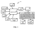
FIG. 1 illustrates anexample system 100 for optimizing the switching ofcapacitor banks 132 and for setting voltage regulator taps 134. According to an example embodiment, astate estimator 102 may be utilized to determine conditions associated with the power distribution network. According to an example embodiment, information such asline impedance 104,control settings 108,substation voltage 110,topology 112, loads 114, and/or end ofline voltage 116 may be utilized by the state estimation block to determine the state of the network. In an example embodiment, thestate estimator 102 may communicate with theIVVC engine 124 directly, or via additional intermediate blocks. For example, azone allocation block 118 and/or aforecast block 122 may be utilized to customize the state estimation information for certain regions or zones of the network and/or certain periods in the future. - According to an example embodiment, the
system 100 may include anIVVC engine 124, that may utilize a capacitorbank switching algorithm 126, an average voltage leveling or flatteningalgorithm 128, and/or a dynamic programming (DP) algorithm 130. According to an example embodiment, theIVVC engine 124, together with the associated blocks, may be utilized for optimizing the switching ofcapacitor banks 132 and for setting voltage regulator taps -
FIG. 2 depicts anexample distribution network 200, according to an example embodiment of the invention. According to an example embodiment, thenetwork 200 may include several microgrids, 202, 204, 206, and 208. In an example embodiment, the microgrids may be associated with the rest of the network, and attached with voltage regulators. -
FIG. 3 depicts an examplereduction processing system 300, according to an example embodiment of the invention. For example, thesystem 200 may include acontroller 302. In an example embodiment, thecontroller 302 may include amemory 303, one ormore processors 306, one or more input/output interfaces 308, and/or one or more network interfaces 310. In an example embodiment, the memory may include anoperating system 312,data 314, and an IVVC engine module 318 (as in 124 ofFIG. 1 ). According to an example embodiment, thesystem 300 may include adatabase 320 and/or a local workstation/display 322, operable for communication with thecontroller 302. In an example embodiment, thecontroller 302 may communicate with apower distribution system 330 via acommunications network 324. According to an example embodiment, thepower distribution system 330 may includedevices 332, such as capacitor banks, voltage regulators, etc. In an example embodiment, thepower distribution system 330 may include portions of thenetwork 334, including radial feeders. In an example embodiment, a remote workstation/display may be in communication with thepower distribution system 330 and /or thecontroller 302. -
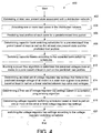
FIG. 4 shows an example flow diagram of amethod 400, according to an example embodiment of the invention. Themethod 400 starts inblock 402 and according to an example embodiment, includes estimating at least one present state associated with a distribution network. Inblock 404, themethod 400 includes allocating one or more load zones in the distribution network. Inblock 406, themethod 400 includes predicting load profiles of each zone for a predetermined time period. Inblock 408, themethod 400 includes determining capacitor bank switching schedules for a predetermined time period based at least in part on the at least one present state and the predicted load profiles. Inblock 410, themethod 400 includes switching capacitor banks according to the capacitor bank switching schedules. Inblock 412, themethod 400 includes running a power flow algorithm to determine the predicted voltages over all nodes in a zone based at least in part on the predicted load profiles. Inblock 414, themethod 400 includes determining an initial set of voltage regulator tap settings that flattens the predicted average voltage of all nodes in a zone over a given time period based at least in part on a linear relation between tap ratios and voltages. Inblock 416, themethod 400 includes determining a final set of voltage regulator tap settings based on a dynamic programming algorithm. Inblock 418, themethod 400 includes determining voltage regulator switching schedules based at least in part on one or more of the initial or final voltage regulator tap settings. Inblock 420, themethod 400 includes switching the voltage regulator tap settings according to the voltage regulator switching schedules. Themethod 400 ends afterblock 420. -
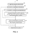
FIG. 5 depicts an example use of a dynamic programming (DP) algorithm for controlling devices in the network. According to an example embodiment, the voltage regulator tap settings may be set using a DP algorithm. In an example embodiment, DP is an optimization method that may be used for generation unit commitment. For example, unit commitment may involve scheduling available generation units (for example, which locations should be receiving power and which locations should not) in a power system for the next N hours (for example, 8 hours) to both meet the load requirements and to achieve the minimum total operational cost. - According to an example embodiment, the dynamic programming may be described as follows: for the Kth hour, there are a limited number of unit combinations, and a minimum cost up to this hour since the 1st hour is desired to be calculated. The following equation may be utilized:

where "K" is the hour number, "I" and "L" represent two different unit combinations, Fcost(K,I) represents the accumulated total cost in the Kth hour when combination "I" is used in this hour, Fcost(K-1,L) represents the accumulated total cost during the previous hour (K-1) when combination "L" was used, Scost(K-1,L:K,I) represents the cost associated with the transition from combination "L" in the new combination "I", and Pcost(K,I) means the cost that will occur in this Kth hour due to the operation with combination "I". In an example embodiment, for each possible combination "I", its associated accumulated cost Fcost(K,I) is evaluated given that Fcost(K-1,L) is already available. According to an example embodiment, this evaluation continues until the final hour is reached. - According to an example embodiment involving IVVC optimization, a similar DP process, as described above may be utilized for scheduling of all available units (e.g., capacitor banks, voltage regulators) for the next N hours to achieve the optimal system performance (e.g., minimum total energy loss). According to an example embodiment, in each hour there are a number of possible scheduling combinations. In an example embodiment, versions of the DP algorithm may be utilized to address certain special features of the IVVC problem. For example, the
IVVC algorithm 500, as shown inFIG. 5 may include the DP to find an optimal solution. According to an example embodiment, thealgorithm 500 may start inblock 502 from a baseline control setting. An outer loop may then includeblocks loop including blocks block 510, and according to an example embodiment, the incremental benefit of the ith iteration from the previous iteration may be evaluated, and if it is less than a predetermined threshold, then thealgorithm 500 may stop and output an optimal solution inblock 512. - According to example embodiments of the invention, expert knowledge may be used in the DP method to limit the number of states to search in each stage. For example, the tap positions of a tap changer may be confined to 9 positions around the "should-be" position based on the actual load condition (whereas the total number of states for each tap changer may be 33 otherwise). According to an example embodiment, a load flow may be determined before every DP to acquire a basic idea of the "should-be" tap position. For example, a tap position too far away from the "should-be" position may result in voltage violations, and may not be preferred. According to an example embodiment, a memory size of 6 may provide an optimal use of memory space. According to an example embodiment, in each iteration, the order of adjusting devices may be randomly generated to avoid being trapped in a limit cycle.
- Accordingly, example embodiments of the invention can provide the technical effects of creating integrated volt/VAR control in power distribution networks that can minimize line losses. Example embodiments of the invention can also provide the technical effects of creating certain systems, methods, and apparatus that can minimize load through conservation voltage reduction. Example embodiments of the invention can also provide the technical effects of creating certain systems, methods, and apparatus that can increase power factor greater than about 0.98 and flatten /adjust voltage to desired setting.
- In example embodiments of the invention, the integrated volt/
VAR control system 100 and thereduction processing system 300 may include any number of hardware and/or software applications that are executed to facilitate any of the operations. - In example embodiments, one or more I/O interfaces may facilitate communication between integrated volt/
VAR control system 100 and thereduction processing system 300 and one or more input/output devices. For example, a universal serial bus port, a serial port, a disk drive, a CD-ROM drive, and/or one or more user interface devices, such as a display, keyboard, keypad, mouse, control panel, touch screen display, microphone, etc., may facilitate user interaction with the integrated volt/VAR control system 100 and thereduction processing system 300. The one or more I/O interfaces may be utilized to receive or collect data and/or user instructions from a wide variety of input devices. Received data may be processed by one or more computer processors as desired in various embodiments of the invention and/or stored in one or more memory devices. - One or more network interfaces may facilitate connection of the integrated volt/
VAR control system 100 and thereduction processing system 300 inputs and outputs to one or more suitable networks and/or connections; for example, the connections that facilitate communication with any number of sensors associated with the system. The one or more network interfaces may further facilitate connection to one or more suitable networks; for example, a local area network, a wide area network, the Internet, a cellular network, a radio frequency network, a Bluetooth™ (owned by Telefonaktiebolaget LM Ericsson) enabled network, a Wi-Fi™ (owned by Wi-Fi Alliance) enabled network, a satellite-based network any wired network, any wireless network, etc., for communication with external devices and/or systems. - As desired, embodiments of the invention may include the integrated volt/
VAR control system 100 and thereduction processing system 300 with more or less of the components illustrated inFIGs. 1 and3 . - Certain embodiments of the invention are described above with reference to block and flow diagrams of systems, methods, apparatuses, and/or computer program products according to example embodiments of the invention. It will be understood that one or more blocks of the block diagrams and flow diagrams, and combinations of blocks in the block diagrams and flow diagrams, respectively, can be implemented by computer-executable program instructions. Likewise, some blocks of the block diagrams and flow diagrams may not necessarily need to be performed in the order presented, or may not necessarily need to be performed at all, according to some embodiments of the invention.
- These computer-executable program instructions may be loaded onto a general-purpose computer, a special-purpose computer, a processor, or other programmable data processing apparatus to produce a particular machine, such that the instructions that execute on the computer, processor, or other programmable data processing apparatus create means for implementing one or more functions specified in the flow diagram block or blocks. These computer program instructions may also be stored in a computer-readable memory that can direct a computer or other programmable data processing apparatus to function in a particular manner, such that the instructions stored in the computer-readable memory produce an article of manufacture including instruction means that implement one or more functions specified in the flow diagram block or blocks. As an example, embodiments of the invention may provide for a computer program product, comprising a computer-usable medium having a computer-readable program code or program instructions embodied therein, said computer-readable program code adapted to be executed to implement one or more functions specified in the flow diagram block or blocks. The computer program instructions may also be loaded onto a computer or other programmable data processing apparatus to cause a series of operational elements or steps to be performed on the computer or other programmable apparatus to produce a computer-implemented process such that the instructions that execute on the computer or other programmable apparatus provide elements or steps for implementing the functions specified in the flow diagram block or blocks.
- Accordingly, blocks of the block diagrams and flow diagrams support combinations of means for performing the specified functions, combinations of elements or steps for performing the specified functions and program instruction means for performing the specified functions. It will also be understood that each block of the block diagrams and flow diagrams, and combinations of blocks in the block diagrams and flow diagrams, can be implemented by special-purpose, hardware-based computer systems that perform the specified functions, elements or steps, or combinations of special-purpose hardware and computer instructions.
- While certain embodiments of the invention have been described in connection with what is presently considered to be the most practical and various embodiments, it is to be understood that the invention is not to be limited to the disclosed embodiments, but on the contrary, is intended to cover various modifications and equivalent arrangements included within the scope of the appended claims. Although specific terms are employed herein, they are used in a generic and descriptive sense only and not for purposes of limitation.
- This written description uses examples to disclose certain embodiments of the invention, including the best mode, and also to enable any person skilled in the art to practice certain embodiments of the invention, including making and using any devices or systems and performing any incorporated methods. The patentable scope of certain embodiments of the invention is defined in the claims, and may include other examples that occur to those skilled in the art. Such other examples are intended to be within the scope of the claims if they have structural elements that do not differ from the literal language of the claims, or if they include equivalent structural elements with insubstantial differences from the literal language of the claims.
Claims (15)
- A method for controlling voltage and reactive power in a distribution network, the method comprising:estimating at least one present state associated with a distribution network (330);allocating one or more load zones in the distribution network (330);predicting load profiles of each zone for a predetermined time period;determining capacitor bank (332) switching schedules for a predetermined time period based at least in part on the at least one present state and the predicted load profiles;switching capacitor banks (332) according to the capacitor bank switching schedules;running a power flow algorithm to determine the predicted voltages over all nodes in a zone based at least in part on the predicted load profiles;determining an initial set of voltage regulator tap settings that flattens the predicted average voltage of all nodes in a zone over a given time period based at least in part on a linear relation between tap ratios and voltages;determining a final set of voltage regulator tap settings based on a dynamic programming algorithm;determining voltage regulator switching schedules based at least in part on one or more of the initial or final voltage regulator tap settings; andswitching the voltage regulator tap settings according to the voltage regulator switching schedules.
- The method of claim 1, wherein estimating the at least one present state comprises estimating at least one of voltage, power factor or reactive loads at nodes of the distribution network (330).
- The method of claim 1 or claim 2, wherein allocating one or more load zones comprises grouping nodes by control sub-systems.
- The method of claim 1, 2 or 3, wherein the one or more load zones are treated as nodes for predicting load profiles.
- The method of any one of claims 1 to 4, wherein predicting the load profiles of each zone is based at least in part on a load forecasting model.
- The method of any one of claims 1 to 5, further comprising:updating estimates of the at least one present state;updating capacitor bank (332) switching schedules; andupdating voltage tap setting switching schedules;
- The method of any one of claims 1 to 6, wherein determining capacitor bank (332) switching schedules is further based at least in part on one of device operation frequency, device volt-amps reactive (VARs), network voltage limits, and network VAR deficit.
- The method of any one of claims 1 to 7, wherein determining voltage regulator switching schedules is further based at least in part on a dynamic programming algorithm and on one or more of device operation frequency, network voltage limits, or leveling the average voltage level in at least one control sub-system.
- An apparatus comprising:at least one memory (303) for storing data and computer-executable instructions; andat least one processor (306) configured to access the at least one memory (303) and further configured to execute the computer-executable instructions for performing the method of any one of the preceding claims.
- A system comprising:at least one power distribution network (330) comprising one or more switchable capacitor banks and one or more adjustable voltage regulators (332); andat least one memory (303) for storing data and computer-executable instructions; and at least one processor (306) configured to access the at least one memory (303) and further configured to execute the computer-executable instructions for controlling voltage and reactive power (VARs) in the distribution network (330) by:estimating at least one present state associated with a distribution network (330);allocating one or more load zones in the distribution network (330);predicting load profiles of each zone for a predetermined time period;determining capacitor bank (332) switching schedules for a predetermined time period based at least in part on the at least one present state and the predicted load profiles;switching capacitor banks (332) according to the capacitor bank switching schedules;running a power flow algorithm to determine the predicted voltages over all nodes in a zone based at least in part on the predicted load profiles;determining an initial set of voltage regulator tap settings that flattens the predicted average voltage of all nodes in a zone over a given time period based at least in part on a linear relation between tap ratios and voltagesdetermining a final set of voltage regulator tap settings based on a dynamic programming algorithm;determining voltage regulator switching schedules based at least in part on one or more of the initial or final voltage regulator tap settings; andswitching the voltage regulator tap settings according to the voltage regulator switching schedules.
- The system of claim 10, wherein estimating the at least one present state comprises estimating at least one of voltage, power factor or reactive loads at nodes of the distribution network (330).
- The system of claim 10 or claim 11, wherein allocating one or more load zones comprises grouping nodes by control sub-systems.
- The system of claim 10, 11 or 12, wherein the one or more load zones are treated as nodes for predicting the load profiles, and/or wherein predicting the load profiles is based at least in part on a load forecasting model.
- The system of any one of claims 10 to 13, further comprising updating estimates of the at least one present state and updating capacitor bank switching schedules.
- The system of any one of claims 10 to 14, wherein determining capacitor bank switching schedules is further based at least in part on one or more of device operation frequency, device volt-amp reactive (VAR), network voltage limits, or network VAR deficit, and/or wherein determining voltage regulator switching schedules is further based at least in part on a dynamic programming algorithm and on one or more of device operation frequency, network voltage limits, or leveling the average voltage level in at least one control sub-system.
Applications Claiming Priority (1)
| Application Number | Priority Date | Filing Date | Title |
|---|---|---|---|
| US13/100,015 US8816531B2 (en) | 2011-01-27 | 2011-05-03 | Systems, methods, and apparatus for integrated volt/VAR control in power distribution networks |
Publications (2)
| Publication Number | Publication Date |
|---|---|
| EP2521237A1 true EP2521237A1 (en) | 2012-11-07 |
| EP2521237B1 EP2521237B1 (en) | 2014-04-30 |
Family
ID=46087470
Family Applications (1)
| Application Number | Title | Priority Date | Filing Date |
|---|---|---|---|
| EP12166232.4A Active EP2521237B1 (en) | 2011-05-03 | 2012-04-30 | Systems, methods, and apparatus for integrated volt/VAR control in power distribution networks |
Country Status (3)
| Country | Link |
|---|---|
| EP (1) | EP2521237B1 (en) |
| JP (1) | JP5961030B2 (en) |
| ES (1) | ES2472543T3 (en) |
Cited By (9)
| Publication number | Priority date | Publication date | Assignee | Title |
|---|---|---|---|---|
| WO2015078598A1 (en) * | 2013-11-26 | 2015-06-04 | Siemens Aktiengesellschaft | Method for computer-assisted configuration of an electrical power grid |
| CN105576830A (en) * | 2015-12-31 | 2016-05-11 | 中国南方电网有限责任公司 | Three-dimensional visualization system for substation |
| WO2016070906A1 (en) * | 2014-11-04 | 2016-05-12 | Abb Technology Ltd | Control of a microgrid |
| EP3107174A1 (en) | 2015-06-19 | 2016-12-21 | Siemens Aktiengesellschaft | Method, control device and system for operating a sub- network of an energy supply network |
| US9997921B2 (en) | 2015-10-07 | 2018-06-12 | General Electric Company | Solar power conversion system and method |
| CN108665133A (en) * | 2017-03-31 | 2018-10-16 | 中国电力科学研究院 | A kind of construction method and system of distribution system operational efficiency evaluation model |
| CN110927480A (en) * | 2019-11-02 | 2020-03-27 | 国网上海市电力公司 | Low-voltage transformer area loss reduction method for HPLC application environment |
| WO2020216667A1 (en) * | 2019-04-26 | 2020-10-29 | Wago Verwaltungsgesellschaft Mbh | System for designing a low-voltage distribution network at a secondary unit substation |
| EP4231478A1 (en) | 2022-02-18 | 2023-08-23 | Siemens Aktiengesellschaft | Method, network controller and system for controlling an electrical local network |
Families Citing this family (8)
| Publication number | Priority date | Publication date | Assignee | Title |
|---|---|---|---|---|
| JP6191229B2 (en) * | 2013-05-15 | 2017-09-06 | 富士電機株式会社 | Tap plan value calculation method, tap command value determination method, control target value calculation method, tap plan value calculation device, tap command value determination device, and tap plan value calculation program |
| US9847647B2 (en) | 2015-10-07 | 2017-12-19 | General Electric Company | Solar power conversion system and method |
| KR101806041B1 (en) * | 2016-09-26 | 2017-12-07 | 한국전력공사 | Control method and system for schedule-based voltage optimization on power distribution line |
| CN106451473B (en) * | 2016-11-03 | 2019-08-20 | 成都信息工程大学 | Power distribution network multiple target voltage control method based on fuzzy multiple agent |
| JP7019538B2 (en) * | 2018-09-27 | 2022-02-15 | 三菱電機ビルテクノサービス株式会社 | Phase-advancing capacitor controller, demand controller and program |
| CN109301838B (en) * | 2018-10-10 | 2020-09-15 | 国网四川省电力公司电力科学研究院 | SVC controller PI parameter optimization method |
| CN110571818B (en) * | 2019-09-10 | 2020-10-27 | 国网湖南省电力有限公司 | Dynamic reactive voltage enhancement type control method for extra-high voltage direct current receiving end power grid |
| US20230187938A1 (en) | 2020-06-23 | 2023-06-15 | Mitsubishi Electric Corporation | Reactive power supplier control device and reactive power supplier control method |
Citations (2)
| Publication number | Priority date | Publication date | Assignee | Title |
|---|---|---|---|---|
| US20100198422A1 (en) * | 2009-02-05 | 2010-08-05 | Abb Research Ltd. | Integrated voltage and var optimization process for a distribution system |
| US20110169461A1 (en) * | 2010-01-14 | 2011-07-14 | Deaver Sr Brian J | System, Device and Method for Regulating Volt-Ampere Reactance in a Power Distribution System |
Family Cites Families (4)
| Publication number | Priority date | Publication date | Assignee | Title |
|---|---|---|---|---|
| JP3102436B2 (en) * | 1990-09-14 | 2000-10-23 | 株式会社アマダ | Power factor improvement device for metalworking line |
| JP4654416B2 (en) * | 2006-05-12 | 2011-03-23 | 独立行政法人産業技術総合研究所 | Distribution system voltage regulation system |
| JP2008271750A (en) * | 2007-04-24 | 2008-11-06 | Toshiba Corp | Method, device and program for voltage reactive power control for power system |
| JP2008278658A (en) * | 2007-04-27 | 2008-11-13 | Toshiba Corp | Power distribution system monitoring control system, method, and program |
-
2012
- 2012-04-25 JP JP2012099345A patent/JP5961030B2/en active Active
- 2012-04-30 EP EP12166232.4A patent/EP2521237B1/en active Active
- 2012-04-30 ES ES12166232.4T patent/ES2472543T3/en active Active
Patent Citations (2)
| Publication number | Priority date | Publication date | Assignee | Title |
|---|---|---|---|---|
| US20100198422A1 (en) * | 2009-02-05 | 2010-08-05 | Abb Research Ltd. | Integrated voltage and var optimization process for a distribution system |
| US20110169461A1 (en) * | 2010-01-14 | 2011-07-14 | Deaver Sr Brian J | System, Device and Method for Regulating Volt-Ampere Reactance in a Power Distribution System |
Cited By (13)
| Publication number | Priority date | Publication date | Assignee | Title |
|---|---|---|---|---|
| US10320192B2 (en) | 2013-11-26 | 2019-06-11 | Siemens Aktiengesellschaft | Method for the computer-assisted configuration of an electrical power grid |
| WO2015078598A1 (en) * | 2013-11-26 | 2015-06-04 | Siemens Aktiengesellschaft | Method for computer-assisted configuration of an electrical power grid |
| US10291024B2 (en) | 2014-11-04 | 2019-05-14 | Abb Schweiz Ag | Control of a microgrid |
| WO2016070906A1 (en) * | 2014-11-04 | 2016-05-12 | Abb Technology Ltd | Control of a microgrid |
| EP3107174A1 (en) | 2015-06-19 | 2016-12-21 | Siemens Aktiengesellschaft | Method, control device and system for operating a sub- network of an energy supply network |
| US9997921B2 (en) | 2015-10-07 | 2018-06-12 | General Electric Company | Solar power conversion system and method |
| CN105576830A (en) * | 2015-12-31 | 2016-05-11 | 中国南方电网有限责任公司 | Three-dimensional visualization system for substation |
| CN108665133A (en) * | 2017-03-31 | 2018-10-16 | 中国电力科学研究院 | A kind of construction method and system of distribution system operational efficiency evaluation model |
| WO2020216667A1 (en) * | 2019-04-26 | 2020-10-29 | Wago Verwaltungsgesellschaft Mbh | System for designing a low-voltage distribution network at a secondary unit substation |
| CN113767547A (en) * | 2019-04-26 | 2021-12-07 | Wago管理有限责任公司 | System for designing a low-voltage distribution network for a local network station |
| CN110927480A (en) * | 2019-11-02 | 2020-03-27 | 国网上海市电力公司 | Low-voltage transformer area loss reduction method for HPLC application environment |
| CN110927480B (en) * | 2019-11-02 | 2022-06-21 | 国网上海市电力公司 | Low-voltage transformer area loss reduction method for HPLC application environment |
| EP4231478A1 (en) | 2022-02-18 | 2023-08-23 | Siemens Aktiengesellschaft | Method, network controller and system for controlling an electrical local network |
Also Published As
| Publication number | Publication date |
|---|---|
| JP2012235680A (en) | 2012-11-29 |
| ES2472543T3 (en) | 2014-07-01 |
| EP2521237B1 (en) | 2014-04-30 |
| JP5961030B2 (en) | 2016-08-02 |
Similar Documents
| Publication | Publication Date | Title |
|---|---|---|
| US8816531B2 (en) | Systems, methods, and apparatus for integrated volt/VAR control in power distribution networks | |
| EP2521237B1 (en) | Systems, methods, and apparatus for integrated volt/VAR control in power distribution networks | |
| Valverde et al. | Model predictive control of voltages in active distribution networks | |
| US9209625B2 (en) | Method and system to co-optimize utilization of demand response and energy storage resources | |
| US9489701B2 (en) | Adaptive energy management system | |
| Krok et al. | A coordinated optimization approach to Volt/VAr control for large power distribution networks | |
| JP6063632B2 (en) | System and method for operating a capacitor bank | |
| US20150058061A1 (en) | Zonal energy management and optimization systems for smart grids applications | |
| CN104578402A (en) | Methods and systems for controlling an electric network | |
| WO2013098233A2 (en) | Adaptation of a power generation capacity and determining of an energy storage unit size | |
| Hans et al. | Minimax model predictive operation control of microgrids | |
| Henao-Muñoz et al. | Energy management system for an isolated microgrid with photovoltaic generation | |
| EP2518853A1 (en) | Systems, methods, and apparatus for coordinated Volt/VAR control in power distribution networks | |
| Hesaroor et al. | Annual energy loss reduction of distribution network through reconfiguration and renewable energy sources | |
| US20120197450A1 (en) | Systems, Methods, and Apparatus for Coordinated Volt/VAR Control in Power Distribution Networks | |
| Michaelson et al. | A predictive energy management strategy with pre-emptive load shedding for an islanded PV-battery microgrid | |
| Tran et al. | Optimal energy management strategies of microgrids | |
| Ozdemir et al. | Supervisory control for coordinating volt/var control devices on a distribution system | |
| CN107949967B (en) | Determination of operating policy of local storage | |
| Silvente et al. | An optimization model for the management of energy supply and demand in smart grids | |
| WO2016025653A1 (en) | Apparatus and methods for control of power flow and battery charge | |
| Hagh et al. | Smart hybrid nanogrids using modular multiport power electronic interface | |
| Abbas et al. | Towards a Near-Zero Energy Building using a Building-Integrated Photovoltaic System with Smart Energy Management Capabilities | |
| Nguyen et al. | Distributed algorithms for peak ramp minimization problem in smart grid | |
| EP4049204A1 (en) | System for configuring demand response for energy grid assets |
Legal Events
| Date | Code | Title | Description |
|---|---|---|---|
| PUAI | Public reference made under article 153(3) epc to a published international application that has entered the european phase |
Free format text: ORIGINAL CODE: 0009012 |
|
| AK | Designated contracting states |
Kind code of ref document: A1 Designated state(s): AL AT BE BG CH CY CZ DE DK EE ES FI FR GB GR HR HU IE IS IT LI LT LU LV MC MK MT NL NO PL PT RO RS SE SI SK SM TR |
|
| AX | Request for extension of the european patent |
Extension state: BA ME |
|
| 17P | Request for examination filed |
Effective date: 20130507 |
|
| RIC1 | Information provided on ipc code assigned before grant |
Ipc: H02J 3/18 20060101AFI20130926BHEP |
|
| GRAP | Despatch of communication of intention to grant a patent |
Free format text: ORIGINAL CODE: EPIDOSNIGR1 |
|
| INTG | Intention to grant announced |
Effective date: 20131219 |
|
| GRAS | Grant fee paid |
Free format text: ORIGINAL CODE: EPIDOSNIGR3 |
|
| GRAA | (expected) grant |
Free format text: ORIGINAL CODE: 0009210 |
|
| AK | Designated contracting states |
Kind code of ref document: B1 Designated state(s): AL AT BE BG CH CY CZ DE DK EE ES FI FR GB GR HR HU IE IS IT LI LT LU LV MC MK MT NL NO PL PT RO RS SE SI SK SM TR |
|
| REG | Reference to a national code |
Ref country code: GB Ref legal event code: FG4D Ref country code: CH Ref legal event code: EP |
|
| REG | Reference to a national code |
Ref country code: AT Ref legal event code: REF Ref document number: 665678 Country of ref document: AT Kind code of ref document: T Effective date: 20140515 |
|
| REG | Reference to a national code |
Ref country code: IE Ref legal event code: FG4D |
|
| REG | Reference to a national code |
Ref country code: DE Ref legal event code: R096 Ref document number: 602012001534 Country of ref document: DE Effective date: 20140612 |
|
| REG | Reference to a national code |
Ref country code: ES Ref legal event code: FG2A Ref document number: 2472543 Country of ref document: ES Kind code of ref document: T3 Effective date: 20140701 |
|
| REG | Reference to a national code |
Ref country code: AT Ref legal event code: MK05 Ref document number: 665678 Country of ref document: AT Kind code of ref document: T Effective date: 20140430 |
|
| REG | Reference to a national code |
Ref country code: LT Ref legal event code: MG4D |
|
| REG | Reference to a national code |
Ref country code: NL Ref legal event code: VDEP Effective date: 20140430 |
|
| PG25 | Lapsed in a contracting state [announced via postgrant information from national office to epo] |
Ref country code: NL Free format text: LAPSE BECAUSE OF FAILURE TO SUBMIT A TRANSLATION OF THE DESCRIPTION OR TO PAY THE FEE WITHIN THE PRESCRIBED TIME-LIMIT Effective date: 20140430 Ref country code: FI Free format text: LAPSE BECAUSE OF FAILURE TO SUBMIT A TRANSLATION OF THE DESCRIPTION OR TO PAY THE FEE WITHIN THE PRESCRIBED TIME-LIMIT Effective date: 20140430 Ref country code: BG Free format text: LAPSE BECAUSE OF FAILURE TO SUBMIT A TRANSLATION OF THE DESCRIPTION OR TO PAY THE FEE WITHIN THE PRESCRIBED TIME-LIMIT Effective date: 20140730 Ref country code: LT Free format text: LAPSE BECAUSE OF FAILURE TO SUBMIT A TRANSLATION OF THE DESCRIPTION OR TO PAY THE FEE WITHIN THE PRESCRIBED TIME-LIMIT Effective date: 20140430 Ref country code: NO Free format text: LAPSE BECAUSE OF FAILURE TO SUBMIT A TRANSLATION OF THE DESCRIPTION OR TO PAY THE FEE WITHIN THE PRESCRIBED TIME-LIMIT Effective date: 20140730 Ref country code: IS Free format text: LAPSE BECAUSE OF FAILURE TO SUBMIT A TRANSLATION OF THE DESCRIPTION OR TO PAY THE FEE WITHIN THE PRESCRIBED TIME-LIMIT Effective date: 20140830 Ref country code: CY Free format text: LAPSE BECAUSE OF FAILURE TO SUBMIT A TRANSLATION OF THE DESCRIPTION OR TO PAY THE FEE WITHIN THE PRESCRIBED TIME-LIMIT Effective date: 20140430 Ref country code: GR Free format text: LAPSE BECAUSE OF FAILURE TO SUBMIT A TRANSLATION OF THE DESCRIPTION OR TO PAY THE FEE WITHIN THE PRESCRIBED TIME-LIMIT Effective date: 20140731 |
|
| PG25 | Lapsed in a contracting state [announced via postgrant information from national office to epo] |
Ref country code: PL Free format text: LAPSE BECAUSE OF FAILURE TO SUBMIT A TRANSLATION OF THE DESCRIPTION OR TO PAY THE FEE WITHIN THE PRESCRIBED TIME-LIMIT Effective date: 20140430 Ref country code: AT Free format text: LAPSE BECAUSE OF FAILURE TO SUBMIT A TRANSLATION OF THE DESCRIPTION OR TO PAY THE FEE WITHIN THE PRESCRIBED TIME-LIMIT Effective date: 20140430 Ref country code: SE Free format text: LAPSE BECAUSE OF FAILURE TO SUBMIT A TRANSLATION OF THE DESCRIPTION OR TO PAY THE FEE WITHIN THE PRESCRIBED TIME-LIMIT Effective date: 20140430 Ref country code: LV Free format text: LAPSE BECAUSE OF FAILURE TO SUBMIT A TRANSLATION OF THE DESCRIPTION OR TO PAY THE FEE WITHIN THE PRESCRIBED TIME-LIMIT Effective date: 20140430 Ref country code: HR Free format text: LAPSE BECAUSE OF FAILURE TO SUBMIT A TRANSLATION OF THE DESCRIPTION OR TO PAY THE FEE WITHIN THE PRESCRIBED TIME-LIMIT Effective date: 20140430 Ref country code: RS Free format text: LAPSE BECAUSE OF FAILURE TO SUBMIT A TRANSLATION OF THE DESCRIPTION OR TO PAY THE FEE WITHIN THE PRESCRIBED TIME-LIMIT Effective date: 20140430 |
|
| PG25 | Lapsed in a contracting state [announced via postgrant information from national office to epo] |
Ref country code: PT Free format text: LAPSE BECAUSE OF FAILURE TO SUBMIT A TRANSLATION OF THE DESCRIPTION OR TO PAY THE FEE WITHIN THE PRESCRIBED TIME-LIMIT Effective date: 20140901 |
|
| REG | Reference to a national code |
Ref country code: IE Ref legal event code: MM4A |
|
| PG25 | Lapsed in a contracting state [announced via postgrant information from national office to epo] |
Ref country code: EE Free format text: LAPSE BECAUSE OF FAILURE TO SUBMIT A TRANSLATION OF THE DESCRIPTION OR TO PAY THE FEE WITHIN THE PRESCRIBED TIME-LIMIT Effective date: 20140430 Ref country code: CZ Free format text: LAPSE BECAUSE OF FAILURE TO SUBMIT A TRANSLATION OF THE DESCRIPTION OR TO PAY THE FEE WITHIN THE PRESCRIBED TIME-LIMIT Effective date: 20140430 Ref country code: DK Free format text: LAPSE BECAUSE OF FAILURE TO SUBMIT A TRANSLATION OF THE DESCRIPTION OR TO PAY THE FEE WITHIN THE PRESCRIBED TIME-LIMIT Effective date: 20140430 Ref country code: BE Free format text: LAPSE BECAUSE OF FAILURE TO SUBMIT A TRANSLATION OF THE DESCRIPTION OR TO PAY THE FEE WITHIN THE PRESCRIBED TIME-LIMIT Effective date: 20140430 Ref country code: SK Free format text: LAPSE BECAUSE OF FAILURE TO SUBMIT A TRANSLATION OF THE DESCRIPTION OR TO PAY THE FEE WITHIN THE PRESCRIBED TIME-LIMIT Effective date: 20140430 Ref country code: RO Free format text: LAPSE BECAUSE OF FAILURE TO SUBMIT A TRANSLATION OF THE DESCRIPTION OR TO PAY THE FEE WITHIN THE PRESCRIBED TIME-LIMIT Effective date: 20140430 |
|
| REG | Reference to a national code |
Ref country code: DE Ref legal event code: R097 Ref document number: 602012001534 Country of ref document: DE |
|
| PLBE | No opposition filed within time limit |
Free format text: ORIGINAL CODE: 0009261 |
|
| STAA | Information on the status of an ep patent application or granted ep patent |
Free format text: STATUS: NO OPPOSITION FILED WITHIN TIME LIMIT |
|
| PG25 | Lapsed in a contracting state [announced via postgrant information from national office to epo] |
Ref country code: IT Free format text: LAPSE BECAUSE OF FAILURE TO SUBMIT A TRANSLATION OF THE DESCRIPTION OR TO PAY THE FEE WITHIN THE PRESCRIBED TIME-LIMIT Effective date: 20140430 |
|
| 26N | No opposition filed |
Effective date: 20150202 |
|
| PG25 | Lapsed in a contracting state [announced via postgrant information from national office to epo] |
Ref country code: IE Free format text: LAPSE BECAUSE OF NON-PAYMENT OF DUE FEES Effective date: 20140430 |
|
| REG | Reference to a national code |
Ref country code: DE Ref legal event code: R097 Ref document number: 602012001534 Country of ref document: DE Effective date: 20150202 |
|
| PG25 | Lapsed in a contracting state [announced via postgrant information from national office to epo] |
Ref country code: SI Free format text: LAPSE BECAUSE OF FAILURE TO SUBMIT A TRANSLATION OF THE DESCRIPTION OR TO PAY THE FEE WITHIN THE PRESCRIBED TIME-LIMIT Effective date: 20140430 |
|
| PG25 | Lapsed in a contracting state [announced via postgrant information from national office to epo] |
Ref country code: MC Free format text: LAPSE BECAUSE OF FAILURE TO SUBMIT A TRANSLATION OF THE DESCRIPTION OR TO PAY THE FEE WITHIN THE PRESCRIBED TIME-LIMIT Effective date: 20140430 |
|
| REG | Reference to a national code |
Ref country code: CH Ref legal event code: PL |
|
| PG25 | Lapsed in a contracting state [announced via postgrant information from national office to epo] |
Ref country code: CH Free format text: LAPSE BECAUSE OF NON-PAYMENT OF DUE FEES Effective date: 20150430 Ref country code: LI Free format text: LAPSE BECAUSE OF NON-PAYMENT OF DUE FEES Effective date: 20150430 |
|
| PG25 | Lapsed in a contracting state [announced via postgrant information from national office to epo] |
Ref country code: MT Free format text: LAPSE BECAUSE OF FAILURE TO SUBMIT A TRANSLATION OF THE DESCRIPTION OR TO PAY THE FEE WITHIN THE PRESCRIBED TIME-LIMIT Effective date: 20140430 |
|
| REG | Reference to a national code |
Ref country code: FR Ref legal event code: PLFP Year of fee payment: 5 |
|
| PG25 | Lapsed in a contracting state [announced via postgrant information from national office to epo] |
Ref country code: SM Free format text: LAPSE BECAUSE OF FAILURE TO SUBMIT A TRANSLATION OF THE DESCRIPTION OR TO PAY THE FEE WITHIN THE PRESCRIBED TIME-LIMIT Effective date: 20140430 |
|
| PG25 | Lapsed in a contracting state [announced via postgrant information from national office to epo] |
Ref country code: HU Free format text: LAPSE BECAUSE OF FAILURE TO SUBMIT A TRANSLATION OF THE DESCRIPTION OR TO PAY THE FEE WITHIN THE PRESCRIBED TIME-LIMIT; INVALID AB INITIO Effective date: 20120430 Ref country code: TR Free format text: LAPSE BECAUSE OF FAILURE TO SUBMIT A TRANSLATION OF THE DESCRIPTION OR TO PAY THE FEE WITHIN THE PRESCRIBED TIME-LIMIT Effective date: 20140430 Ref country code: LU Free format text: LAPSE BECAUSE OF NON-PAYMENT OF DUE FEES Effective date: 20140430 |
|
| REG | Reference to a national code |
Ref country code: FR Ref legal event code: PLFP Year of fee payment: 6 |
|
| PGFP | Annual fee paid to national office [announced via postgrant information from national office to epo] |
Ref country code: ES Payment date: 20170503 Year of fee payment: 6 |
|
| REG | Reference to a national code |
Ref country code: FR Ref legal event code: PLFP Year of fee payment: 7 |
|
| PG25 | Lapsed in a contracting state [announced via postgrant information from national office to epo] |
Ref country code: MK Free format text: LAPSE BECAUSE OF FAILURE TO SUBMIT A TRANSLATION OF THE DESCRIPTION OR TO PAY THE FEE WITHIN THE PRESCRIBED TIME-LIMIT Effective date: 20140430 |
|
| PG25 | Lapsed in a contracting state [announced via postgrant information from national office to epo] |
Ref country code: AL Free format text: LAPSE BECAUSE OF FAILURE TO SUBMIT A TRANSLATION OF THE DESCRIPTION OR TO PAY THE FEE WITHIN THE PRESCRIBED TIME-LIMIT Effective date: 20140430 |
|
| REG | Reference to a national code |
Ref country code: ES Ref legal event code: FD2A Effective date: 20190912 |
|
| PG25 | Lapsed in a contracting state [announced via postgrant information from national office to epo] |
Ref country code: ES Free format text: LAPSE BECAUSE OF NON-PAYMENT OF DUE FEES Effective date: 20180501 |
|
| PGFP | Annual fee paid to national office [announced via postgrant information from national office to epo] |
Ref country code: FR Payment date: 20230321 Year of fee payment: 12 |
|
| PGFP | Annual fee paid to national office [announced via postgrant information from national office to epo] |
Ref country code: DE Payment date: 20230321 Year of fee payment: 12 |
|
| REG | Reference to a national code |
Ref country code: DE Ref legal event code: R081 Ref document number: 602012001534 Country of ref document: DE Owner name: GE DIGITAL HOLDINGS LLC, SAN RAMON, US Free format text: FORMER OWNER: GENERAL ELECTRIC CO., SCHENECTADY, N.Y., US |
|
| REG | Reference to a national code |
Ref country code: GB Ref legal event code: 732E Free format text: REGISTERED BETWEEN 20240111 AND 20240117 |
|
| PGFP | Annual fee paid to national office [announced via postgrant information from national office to epo] |
Ref country code: GB Payment date: 20240320 Year of fee payment: 13 |