EP2474092B1 - Variable coil configuration system, apparatus and method - Google Patents
Variable coil configuration system, apparatus and method Download PDFInfo
- Publication number
- EP2474092B1 EP2474092B1 EP10814529.3A EP10814529A EP2474092B1 EP 2474092 B1 EP2474092 B1 EP 2474092B1 EP 10814529 A EP10814529 A EP 10814529A EP 2474092 B1 EP2474092 B1 EP 2474092B1
- Authority
- EP
- European Patent Office
- Prior art keywords
- switches
- coils
- electrically
- electric machine
- series
- Prior art date
- Legal status (The legal status is an assumption and is not a legal conclusion. Google has not performed a legal analysis and makes no representation as to the accuracy of the status listed.)
- Active
Links
- 238000000034 method Methods 0.000 title claims description 24
- 230000008878 coupling Effects 0.000 claims description 18
- 238000010168 coupling process Methods 0.000 claims description 18
- 238000005859 coupling reaction Methods 0.000 claims description 18
- 230000002441 reversible effect Effects 0.000 claims description 5
- 238000004804 winding Methods 0.000 description 21
- 238000013461 design Methods 0.000 description 11
- 238000001514 detection method Methods 0.000 description 9
- 239000012530 fluid Substances 0.000 description 9
- 238000006243 chemical reaction Methods 0.000 description 8
- 230000006698 induction Effects 0.000 description 8
- 238000004519 manufacturing process Methods 0.000 description 7
- 239000004065 semiconductor Substances 0.000 description 7
- 230000006870 function Effects 0.000 description 6
- 238000002955 isolation Methods 0.000 description 6
- 230000008901 benefit Effects 0.000 description 5
- 238000010586 diagram Methods 0.000 description 4
- 238000012545 processing Methods 0.000 description 4
- 230000009471 action Effects 0.000 description 3
- 239000000872 buffer Substances 0.000 description 3
- 239000003990 capacitor Substances 0.000 description 3
- 230000008859 change Effects 0.000 description 3
- 238000010276 construction Methods 0.000 description 3
- 238000012544 monitoring process Methods 0.000 description 3
- 230000004044 response Effects 0.000 description 3
- 239000007787 solid Substances 0.000 description 3
- RYGMFSIKBFXOCR-UHFFFAOYSA-N Copper Chemical compound [Cu] RYGMFSIKBFXOCR-UHFFFAOYSA-N 0.000 description 2
- 229910052802 copper Inorganic materials 0.000 description 2
- 239000010949 copper Substances 0.000 description 2
- 238000012937 correction Methods 0.000 description 2
- 238000005259 measurement Methods 0.000 description 2
- 230000001360 synchronised effect Effects 0.000 description 2
- 238000012935 Averaging Methods 0.000 description 1
- 239000000956 alloy Substances 0.000 description 1
- 229910045601 alloy Inorganic materials 0.000 description 1
- 230000003321 amplification Effects 0.000 description 1
- 238000003491 array Methods 0.000 description 1
- 230000004323 axial length Effects 0.000 description 1
- 230000002457 bidirectional effect Effects 0.000 description 1
- 230000005540 biological transmission Effects 0.000 description 1
- 230000000903 blocking effect Effects 0.000 description 1
- 238000004891 communication Methods 0.000 description 1
- 239000013078 crystal Substances 0.000 description 1
- 230000001419 dependent effect Effects 0.000 description 1
- 230000005669 field effect Effects 0.000 description 1
- 238000009499 grossing Methods 0.000 description 1
- 230000036039 immunity Effects 0.000 description 1
- 238000009434 installation Methods 0.000 description 1
- 239000000463 material Substances 0.000 description 1
- 239000000203 mixture Substances 0.000 description 1
- 238000012986 modification Methods 0.000 description 1
- 230000004048 modification Effects 0.000 description 1
- 238000003199 nucleic acid amplification method Methods 0.000 description 1
- 230000008569 process Effects 0.000 description 1
- 230000001172 regenerating effect Effects 0.000 description 1
- 230000009466 transformation Effects 0.000 description 1
- 230000001052 transient effect Effects 0.000 description 1
Images


Classifications
-
- H—ELECTRICITY
- H02—GENERATION; CONVERSION OR DISTRIBUTION OF ELECTRIC POWER
- H02M—APPARATUS FOR CONVERSION BETWEEN AC AND AC, BETWEEN AC AND DC, OR BETWEEN DC AND DC, AND FOR USE WITH MAINS OR SIMILAR POWER SUPPLY SYSTEMS; CONVERSION OF DC OR AC INPUT POWER INTO SURGE OUTPUT POWER; CONTROL OR REGULATION THEREOF
- H02M7/00—Conversion of ac power input into dc power output; Conversion of dc power input into ac power output
- H02M7/02—Conversion of ac power input into dc power output without possibility of reversal
- H02M7/04—Conversion of ac power input into dc power output without possibility of reversal by static converters
- H02M7/06—Conversion of ac power input into dc power output without possibility of reversal by static converters using discharge tubes without control electrode or semiconductor devices without control electrode
-
- H—ELECTRICITY
- H02—GENERATION; CONVERSION OR DISTRIBUTION OF ELECTRIC POWER
- H02P—CONTROL OR REGULATION OF ELECTRIC MOTORS, ELECTRIC GENERATORS OR DYNAMO-ELECTRIC CONVERTERS; CONTROLLING TRANSFORMERS, REACTORS OR CHOKE COILS
- H02P25/00—Arrangements or methods for the control of AC motors characterised by the kind of AC motor or by structural details
- H02P25/16—Arrangements or methods for the control of AC motors characterised by the kind of AC motor or by structural details characterised by the circuit arrangement or by the kind of wiring
- H02P25/18—Arrangements or methods for the control of AC motors characterised by the kind of AC motor or by structural details characterised by the circuit arrangement or by the kind of wiring with arrangements for switching the windings, e.g. with mechanical switches or relays
- H02P25/188—Arrangements or methods for the control of AC motors characterised by the kind of AC motor or by structural details characterised by the circuit arrangement or by the kind of wiring with arrangements for switching the windings, e.g. with mechanical switches or relays wherein the motor windings are switched from series to parallel or vice versa to control speed or torque
-
- H—ELECTRICITY
- H02—GENERATION; CONVERSION OR DISTRIBUTION OF ELECTRIC POWER
- H02P—CONTROL OR REGULATION OF ELECTRIC MOTORS, ELECTRIC GENERATORS OR DYNAMO-ELECTRIC CONVERTERS; CONTROLLING TRANSFORMERS, REACTORS OR CHOKE COILS
- H02P29/00—Arrangements for regulating or controlling electric motors, appropriate for both AC and DC motors
- H02P29/02—Providing protection against overload without automatic interruption of supply
- H02P29/032—Preventing damage to the motor, e.g. setting individual current limits for different drive conditions
-
- H—ELECTRICITY
- H02—GENERATION; CONVERSION OR DISTRIBUTION OF ELECTRIC POWER
- H02P—CONTROL OR REGULATION OF ELECTRIC MOTORS, ELECTRIC GENERATORS OR DYNAMO-ELECTRIC CONVERTERS; CONTROLLING TRANSFORMERS, REACTORS OR CHOKE COILS
- H02P9/00—Arrangements for controlling electric generators for the purpose of obtaining a desired output
- H02P9/02—Details
-
- Y—GENERAL TAGGING OF NEW TECHNOLOGICAL DEVELOPMENTS; GENERAL TAGGING OF CROSS-SECTIONAL TECHNOLOGIES SPANNING OVER SEVERAL SECTIONS OF THE IPC; TECHNICAL SUBJECTS COVERED BY FORMER USPC CROSS-REFERENCE ART COLLECTIONS [XRACs] AND DIGESTS
- Y02—TECHNOLOGIES OR APPLICATIONS FOR MITIGATION OR ADAPTATION AGAINST CLIMATE CHANGE
- Y02B—CLIMATE CHANGE MITIGATION TECHNOLOGIES RELATED TO BUILDINGS, e.g. HOUSING, HOUSE APPLIANCES OR RELATED END-USER APPLICATIONS
- Y02B70/00—Technologies for an efficient end-user side electric power management and consumption
- Y02B70/10—Technologies improving the efficiency by using switched-mode power supplies [SMPS], i.e. efficient power electronics conversion e.g. power factor correction or reduction of losses in power supplies or efficient standby modes
-
- Y—GENERAL TAGGING OF NEW TECHNOLOGICAL DEVELOPMENTS; GENERAL TAGGING OF CROSS-SECTIONAL TECHNOLOGIES SPANNING OVER SEVERAL SECTIONS OF THE IPC; TECHNICAL SUBJECTS COVERED BY FORMER USPC CROSS-REFERENCE ART COLLECTIONS [XRACs] AND DIGESTS
- Y02—TECHNOLOGIES OR APPLICATIONS FOR MITIGATION OR ADAPTATION AGAINST CLIMATE CHANGE
- Y02E—REDUCTION OF GREENHOUSE GAS [GHG] EMISSIONS, RELATED TO ENERGY GENERATION, TRANSMISSION OR DISTRIBUTION
- Y02E10/00—Energy generation through renewable energy sources
- Y02E10/70—Wind energy
- Y02E10/72—Wind turbines with rotation axis in wind direction
Definitions
- This application generally relates to electric machines with coils or windings (e.g ., generators, motors), and more particularly to systems, apparatus and methods that configure coils or windings of multistage electric machines.
- the amount of energy captured from the energy source may only be a fraction of the total of the capturable energy. For example, in a typical wind farm, that fraction may be one half, or less of the total capturable energy.
- variable-speed conventional turbine/generator/transformer system The power flow though a variable-speed conventional turbine/generator/transformer system is restricted in the range of power that can be output, i.e ., from a minimum output power to a rated output power, due to limitations of the generator, the power converter (if present), and/or the output transformer used within the system.
- This restriction arises because conventional electromagnetic generators have reduced efficiency at lower power levels, as does the power converter (if present) and particularly the transformer that couples power to the electrical load.
- an engineering design decision is usually made to limit the power rating of the generator (and any associated power converter, power conditioner or power filter, if present) and the associated output transformer so as to optimize efficiency over a restricted range of power.
- a multi-stage generator may be used in the turbine system.
- a multi-stage generator is an electric machine operating as an electrical generator that takes mechanical energy from a prime mover and generates electrical energy, usually in the form of alternating current (AC) power.
- AC alternating current
- Such a multi-stage generator is disclosed in US Patent No. 7081696 and U.S. Patent Application Publication No. 2008088200 .
- An advantage of a multi-stage generator over a conventional generator is that a multi-stage generator can be dynamically sized depending on the power output of the turbine.
- a conventional generator is effective at capturing energy from the energy source over a limited range of fluid speeds, whereas a multi-stage generator is able to capture energy over an extended range of fluid speeds of the energy source, due to staged power characteristics.
- the electrical power that is generated from a multi-stage generator is variable in nature, meaning the output power waveforms produced may vary from time to time, for example in: voltage amplitude; current amplitude; phase; and/or frequency.
- a multi-stage generator may include a plurality of induction elements, each of which generates its own power waveform, which may differ in voltage amplitude, current amplitude, phase, and/or frequency, from that generated by other induction elements within the generator.
- An electrical load such as an electric utility power grid may not be capable of directly consuming the electrical power that is generated by a multi-stage generator, as the power generated may not be in a suitable form, for example with respect to waveform shape as a function of time, voltage amplitude, current amplitude, phase, and/or frequency, as may be required by the electrical load.
- An electrical load such as a utility power grid typically expects from a turbine electrical generation system a single-phase, or split-phase, or 3-phase voltage or current waveform that is usually sinusoidal, and relatively stable.
- a multi-stage generator typically generates varying waveforms.
- U.S. Patent 3,984,750 is directed to an alternator-rectifier unit in which separate three-phase windings are connected to individual rectifiers arranged for series-parallel switching to improve current-voltage characteristics. Notably, such employs switching on the direct current (DC) side of the rectifier. Such circuit is associated with relatively high losses, experiencing four diode voltage drops. Such is not extended beyond a single coil configuration switch.
- U.S. Patent Application No. 2007/0182273 describes circuitry for configuring generator coils in various series/parallel combinations. This disclosure has 4 coils configured using 14 switches. Each switch carries multiple coil loads, up to full section current in parallel case. The system uses 12 switches in circuit for a series case, and up to 10 switches in circuit in parallel case.
- DE19733208 describes a he circuit arrangement that is used for a vehicle three-phase generator or alternator.
- the winding of the machine is made up of two partial windings (1,2).
- the voltages and currents at the outputs of the two partial coils are rectified.
- the outputs of one partial coil are connected to the inputs of a first rectifier (15).
- the outputs of the other half-winding (2) are connected to the inputs of another rectifier (16). Both half coils are wound in the same direction and have the same connections.
- Each output of one half winding (1) is connected via the circuit of two switchable elements with two outputs of the other half winding (2). Thus when the switch line is connected through the two half windings are electrically connected in series.
- US2006/273766 describes a high-power permanent-magnet generator in which a stator winding is divided into a first winding part and second winding parts to keep a number of turns less, and capacitors are installed between any different phases to store a current therein to raise a voltage and thereby yielding a high output.
- WO8807782 describes a wind-powered magneto-electric generator of which magnetic rotors (36, 37) are on a common shaft (17) direct-driven from a wind-turbine (Figs, 8, 9 and 10) to generate in stators (18, 19) an electromotive force (EMF) which is controlled relative to the input power by switching the stators into series or parallel in response to the shaft speed and a signal derived and fed back from the EMF function.
- EMF electromotive force
- WO2007098227 describes a power tool having an electronically commutated DC motor capable of providing various operating modes ranging from a maximum efficiency operating mode to a maximum power operating mode.
- Embodiments of the present system and method include a variable configuration controller (referred to as a "VCC”) system and method to connect multiple generator coil windings in varying series or parallel combinations to maintain a relatively consistent output voltage (for example, within a 2:1 range) in response to varying input shaft speeds.
- VCC variable configuration controller
- the VCC may be used with various electric machines, for instance single or multi-phase generators, and provides a rectified DC output from each AC phase input from an induction element.
- the DC output may optionally be used with a Power Factor Correction ("PFC”) circuit to increase the efficiency of generator operation by smoothing the current wave shape to a near sinusoid.
- PFC Power Factor Correction
- the systems, apparatus and methods allow the configuration of multiple coils or windings in variable series/parallel combinations.
- the systems, apparatus and methods may also allow switching series and parallel coils or windings in tandem with rectification, rather than switching on the DC side, post-rectification. This may be accomplished using fewer switches than in previously described systems. In fact, parallel configuration can be achieved with no switches or with the switches open.
- the VCC system advantageously employs AC-side parallel/series switching, combined with AC/DC rectification, and DC/DC blocking capabilities of the bridge rectifiers.
- the diode rectifier bridges While the AC side switches (e.g., relay, IGBT, SSR, or any other switch) perform part of the switching action, the diode rectifier bridges perform series combination, isolation of intermediate step points , and connection of the appropriate coil terminals, and only those terminals, to the output. Thus, the diode rectifier bridges allow not only AC-DC rectification, but parallel current sharing, intermediate step isolation, and conduction of the 'end point' terminals to the DC bus output.
- the AC side switches e.g., relay, IGBT, SSR, or any other switch
- VCC system described herein avoids the high losses associated with other devices. For example, the VCC system produces only two diode drops no matter how many series/parallel coils are used or configured, compared to four diode drops of the device described in U.S. patent 3,984,750 .
- the VCC system described herein also employs a relatively simple switching scheme. Such advantageously avoids the complex switching scheme using a large number of switches, and associated losses, such as that described in U.S. Patent Application Publication No. 2007/0182273 . That device uses 4 to 12 series switch elements for four coils, in contrast to the 1:1 ratio achievable using the VCC system described herein. Additionally, device of the U.S. Patent Application Publication No. 2007/0182273 requires the switch contacts to carry the parallel current of all coils. In contrast, VCC system described herein requires the switch contacts to carry the series current of only one coil per switch. This is a significant advantage since such reduces power losses, as well as allowing use of lower rated switches.
- the VCC system described herein provides some inherent fault tolerance against both open and shorted coils. For example, if a given coil is short-circuited, or has a lower output voltage than other coils, the diode bridge rectifiers will isolate that coil from parallel combination. In the case that the shorted coil is series combined with other coils, the whole string may be isolated from the output if there are other series-parallel circuits or the output voltage may be reduced if there is only one series coil string (i.e., all coils series mode). Importantly, in no case is the output loaded down by the shorted coil, as would occur in AC-side switching type devices described in U.S. Patent Application Publication No. 2007/0182273 . Also for example, if a given coil is open-circuited, the diode bridge rectifiers will isolate that coil from parallel combination. In the case that the open coil is series combined with other coils, the whole string containing the open coil will be isolated from the output.
- a dual-element TRIAC/relay switch combination provides further advantages.
- fast switching of the semiconductor element e.g., TRIAC, or IGBT, or FET, or SSR
- the semiconductor element e.g., TRIAC, or IGBT, or FET, or SSR
- low power loss of relay contacts means significantly higher switching efficiency of the VCC system.
- This combination adds additional cost and complexity, but the VCC system is unique in requiring as few as a single ( i.e., one) switch element per coil and only requiring the switch carry the series current for that coil only. Hence, this extra cost and complexity is acceptable.
- the VCC system may advantageously employ a common heat exchange structure (e.g., heat sink) for all diode bridge rectifiers in a given VCC.
- a common heat exchange structure e.g., heat sink
- a common heat exchange structure maintains an approximately equal temperature of all diodes so that their forward voltage drop also remains equal. This equal forward voltage drop helps maintain equal current sharing.
- VCC System 1 Bridge rectifiers D1-D5, collectively 10 Coil connector blocks J1-J6, collectively 20 Semiconductor switches, e.g. Triacs Q1-Q5, collectively 30 Snubber network 40 Relay 50 Expansion port 55 Gate drive 70 DC bus output connection 80 Controller 90 Analog multiplexer 100 RS485 interface 110 Power source 120 Amplifiers 130 Heat sink 140
- a VCC system 1 ( Figures 1A-1H , 2A-2F ) is a power electronics system configured to adjust multiple induction elements, such as coil windings of an electric machine (e.g ., generator, electric motor), in various series and parallel combinations to maintain a relatively constant output voltage in response to varying input shaft speeds.
- the electric machine may use permanent magnets, electromagnets, a hybrid, and be core or coreless.
- a VCC system 1 may be used with a multi-phase electric machine, although each phase is managed in isolation by a separate circuit embodiment.
- a VCC system 1 can provide rectified DC output from each AC phase input, where the VCC system 1 is primarily intended for use with a subsequent Power Factor Correction (PFC) circuit.
- PFC Power Factor Correction
- VCC system 1 may also be used without PFC on the DC outputs.
- a VCC system 1 could be used with a PFC at the DC output, or a non-PFC with a single DC output.
- An alternative embodiment of a VCC system 1 could output AC.
- the VCC system 1 may operate using a number of devices or elements separately or in cooperation to connect the coils in the electric machine electrically in series and/or parallel. These devices or elements may include triacs, relays ( e.g ., solid state relays), bridge rectifiers, transistors and combinations thereof.
- the series coil configuration can be achieved by connecting the top side of one coil winding to the bottom side of the next coil winding by any suitable means.
- a VCC system 1 may work in conjunction with a power conversion system, such as the power conversion system and method described in U.S. Provisional Patent Application No. 60/094,007 .
- FIG. 1 shows a VCC system 1a, according to one illustrated embodiment.
- the VCC system 1a includes a plurality of bridge rectifiers D1-D6 (collectively 10).
- Each bridge rectifier 10 corresponds to a coil, from which bridge rectifier 10 is electrically coupled to receive AC input.
- the coils may be connected by suitable connectors J1-J6 (collectively 20).
- J1-J6 (collectively 20).
- six bridge rectifiers 10 may be present, as illustrated in Figures 1A and 1B .
- Bridge rectifiers 10 may provide several functions for the VCC system 1a, including:
- bridge rectifiers 10 may be GBU8U devices, each capable of 8A, 600V operation. Such requires an adequate heat sink.
- a maximum output power of 420V RMS (600VDC peak) at 48A RMS (6 x 8A), or 20.2kW is possible. If only six coils are present, the six parallel coil mode represents the maximum output power possible from the VCC system 1a. At 220V RMS, 48A RMS, the maximum output in six parallel coil mode is 10.6kW (per phase).
- the bridge rectifiers 10 are therefore involved in providing the coil series and parallel switching function.
- the bridge rectifiers 10 also convert the AC current to DC current for receipt by a DC bus for transmission to an electrical load. Also, if a coil has an internal short, its lower output voltage causes the bridge rectifier 10 to which it is connected to be reverse biased, automatically isolating that coil from the output circuit. Likewise, while all coils are normally active, should a coil be switched off, the appropriate bridge rectifier 10 will automatically isolate that coil from the output circuit.
- the six parallel coil mode can be used for over-speed or over-torque operation for peak load handling.
- the operating point current at the nominal operating point should be lowered from 8A to allow higher currents at peak load to be within the bridge diode ratings.
- bridge rectifiers 10 diode ratings may be at least 15A.
- Active switches may be placed across one or more of bridge rectifiers 10. These switches may be FETs, IGBTs, bipolar transistors, or any other suitable DC switching devices with high speed operation. These switches may be pulse-width modulated (PWM) to apply a variable DC voltage from the output bus to the coil connector blocks 20, thereby capable of reversing or changing the operation of the generator to that of a speed-controlled motor. In particular, the switches (not shown) may reverse current flow from the DC bus to the coils of the electric machine at appropriate times in order to provide a rotating magnetic field suitable for motor operation.
- PWM pulse-width modulated
- the semiconductor switches 30 may take a variety of forms, for example triacs, IGBTs, FETs, SSRs.
- Triacs are a bidirectional electronic switches for AC current that conducts current in either direction. The triac conducts and latches ( i.e ., stays ON) until the current load is removed, which for example may occur at zero crossing or a minimal level of current.
- five semiconductor switches 30 such as triacs, individually labeled as Q1 through Q5, may be used to control six coils of an electric machine.
- These triacs Q1-Q5 can be individually controlled by controller 90 ( Figure 2D ) to enable series and parallel coil combinations in a six coil machine as follows:
- Coil series configuration controlled by triacs 30 provides enhanced operation due to lower current waveform distortion achieved by 'zero cross switching' of triac 30, i.e., when the AC current waveform drawn from the switched coil is at its minimum value.
- the VCC system 1 may also include a number of relay switches 50, which may operate independently, or in conjunction with triacs 30.
- the VCC system illustrated in Figure 1 includes five relay switches, individually labeled K1-K5, each electrically in parallel with a respective one of the triacs Q1-Q5.
- Relay switches 50 provide for a low level of losses when switching, but are slow to switch ( i.e., change state) in reaction to a switch command.
- Triacs 30 react to switch commands quickly but have higher losses when compared to relay switches 50.
- the appropriate triac 30 reacts first and switches state accordingly. Then, the corresponding relay switch 50 switches or changes state, taking over the load. The corresponding triac 30 is disengaged for this purpose, until the next switching or change takes place.
- the VCC system 1 may employ a number of box headers (e.g ., 10x2) J11 ( Figure 1D ), J12 ( Figure 1E ) to provide selectively detachable communicative coupling between a controller 90 ( Figure 2D ) and various other VCC system elements, for example the triacs Q1-Q5 ( Figures 1A , 1B ) and relays K1-K5 ( Figures 1A , 1B ).
- box headers e.g ., 10x2
- J11 Figure 1D
- J12 Figure 1E
- Respective gate drive circuits 70a-70f are repeated at each zero cross to ensure triac 30 "ON" control. Changing triac 30 drive signals G Q1-G Q5 only at zero cross also prevents unintended series configurations (the zero cross detection ensures all triacs 30 except those with a gate drive are "OFF").
- the zero cross detection circuits may use A/D conversion of both voltage and current inputs, and a digital filter for averaging and zero cross estimation to increase robustness and frequency range.
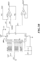
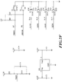
- Zero crossing detection may be performed in digital signal processing in controller 90 (e.g ., U101, Figure 2D ) by measuring voltages VMON1- VMON6 and currents CMON1- CMON 6 through multiplexers 100 ( e.g ., U4, U5, Figures 2A and 2B ), signal amplifiers 130 ( Figures 2A and 2B ) and buffers U7 ( Figures 2A , 2B ), and the processor internal A/D converter within controller 90 ( e.g ., U101, Figure 2D ).
- controller 90 e.g ., U101, Figure 2D
- a current monitor circuit may be present for zero cross detection.
- the current monitor circuit could be used for zero cross trigger switching of triacs 30.
- current monitoring resistors R49-R54 ( Figures 1A and 1B ) present a voltage drop proportional to current flow in each coil, selected by multiplexers 100 ( e.g ., U4, U5, Figures 2A and 2B ), amplified by amplifiers 130, and converted to digital representation by an A/D converter within controller 90 ( e.g ., U101, Figure 2D ).
- snubber networks 40 Within the 100 Ohm and 0.1uF networks, across each triac 30 are snubber networks 40 (only one called out in Figure 1A and Figure 4 ).
- the snubber networks 40 absorb voltage transients which otherwise might cause false triggers of triacs 30 at turn-OFF or zero-cross points.
- Snubber network 40 may use a carbon-composition resistor that has high pulse handling capabilities (many kW for short pulses), but is only 1/2W continuous rated.
- the 100ohm 0.1uF combination may be limited to 110VAC at 1kHz or 220VAC at 500Hz due to continuous power dissipation in the snubber resistance. Higher voltage operation of the VCC system 1 requires lowering both the resistance and capacitance value.
- the snubber could be designed for greater voltage, e.g ., a 47 ohm and 0.033uF snubber would allow for 500VAC at 1kHz.
- Bridge rectifiers 10 when connected to a load, may also act as snubbers for transient energy across the switching elements, whether those elements be triacs 30, relay contacts 50, or transistors. Such a configuration may eliminate the need for the snubber network 40. Additionally, there are triacs 30 available (for example those sold in association with the trademark ALTERNISTOR®), that do not require snubber networks 40.
- Gate drive 70 circuits may include isolation transformers T1-T6 ( Figure 1H ), coupling capacitors (not shown), such as 0.47uF AC coupling capacitors, and coupling discharge resistances (not shown), typically 10k, coupled across a primary side of the isolation transformers T1-T6.
- the digital control output circuits are isolated from the high voltage at the triac gates by transformers T1-T6.
- a 2:1 winding ratio provides a 4:1 impedance transformation so that controller 90 may supply up to the required 50mA triac gate drive level.
- 74HCT574 buffer/driver/level converter circuits U102, U103 ( Figure 2C ) may be included within gate drive circuit 70 ( Figure 1H ).
- circuits U102, U103 isolate the gate drive circuit 70 power supply noise from controller 90, allow a level convert to a 5V drive, and free input/output (I/O) pins.
- these circuits U102, U103 may translate the 3.3 processor or controller 90 ( e.g., U1, Figure 2D ) logic levels to 5V levels at higher current capacity suitable for driving relay drivers U2 of the power circuit board ( i.e., VCC_PWR), LEDs D101-D104 ( Figure 2F ) of the control circuit board ( i.e., VCC_MCU), and triac transformers T1-T6 of the power circuit board ( i.e., VCC_PWR).
- Relay contacts may be added across the triacs 30 to reduce loss, at the cost of additional complexity.
- Such contacts may be +24V coil, 10A SPST contacts.
- An expansion port 55 may be provided within the VCC system 1.
- an extra triac Q6 and/or relay switch (as appropriate) K6 at one 'end' allows connection to another VCC system module to expand the coil series switching capability.
- This 'switch' expansion port 55 may be coupled to the 'unswitched' side of the next VCC system module ( i.e., the 'top' of one coil stack connected to the 'bottom' of the next coil stack).
- the VCC system 1 may include a heat exchange structure (e.g ., heat sink, heat spreader and/or heat pipe) 140.
- a heat exchange structure e.g ., heat sink, heat spreader and/or heat pipe
- the heat exchange structure 140 can provide at least three functions.
- the heat exchange structure 140 may remove heat from bridge rectifiers 10.
- the heat exchange structure 140 may remove heat from triacs 30.
- the heat exchange structure 140 may equalize bridge rectifier 10 temperatures, which may facilitate proper parallel mode current sharing between bridge rectifiers 10.
- a relatively small heat exchange structure 140 such as a small heat sink may be capable of less than 50W of dissipation, which is suitable for greater than 2kW of output power per phase.
- Amplifiers 130 may provide differential amplification of the low-voltage current monitoring signal produced in the low-value (approximately 0.004 ohms) current shunt resistances formed by small lengths of wire or printed circuit board traces.
- Amplifiers 130 may have a differential gain of 100 and an output range of about 4V which results in a full scale current capability of about 10A.
- These amplifier circuits need not be precise due to variations in current shunt resistance values, but are intended to give representative current measurement results, which is useful for zero cross detection (digital signal processing mode), fault detection, and operational reporting.
- the controller 90 may take a variety of forms.
- the controller 90 may take the form of a microcontroller, microprocessor, application specific integrated circuit or programmable gate array.
- the controller 90 may take the form of a PIC16F883 microcontroller (U101).
- the controller 90 is the core of the VCC system 1, controlling operation, providing a memory, a processor, A/D conversion, digital I/O, timing functions, as well as serial communications.
- a 20MHz clock crystal may result in 5MIPS instruction execution speed.
- Firmware may be programmed in approximately 1500 lines of assembly code.
- the microcontroller code may have a C source, which would improve portability and readability and increase the capability of the VCC system 1 to deal with more complex systems.
- Controller 90 may take the form of a higher performance device, for example a PIC18, which would provide faster processing (10+ MIPS), a hardware multiplier for signal processing, a faster A/D converter, and C code support, providing more memory and speed.
- a higher performance device for example a PIC18, which would provide faster processing (10+ MIPS), a hardware multiplier for signal processing, a faster A/D converter, and C code support, providing more memory and speed.
- Root-Mean-Square (RMS) current and voltage measurements may be added to the code to support power and power factor (PF) reporting, allow zero cross detection at non-unity PF, provide fault detection support, measure input cycle frequency, and automatically adjust triac 30 gate drive circuit 70 timeouts.
- PF power factor
- a daughterboard configuration could be used for controller 90, which would allow the main power board (VCC_PWR) to have 3oz or 4oz copper, with associated large trace/space design rules and through-hole construction, while the controller board (VCC_MCU) can be standard 1oz copper with surface mount device (SMD) components and finer design rules.
- the controller 90 or main power board (VCC_PWR) could each be re-designed separately and firmware updates could be handled by easy replacement of the module rather than the entire power circuit.
- Analog multiplexers 100 may be added to select inputs to measure additional analog inputs to controller 90.
- two 74HC4051 8-1 analog multiplexers may be added, which requires 15 analog inputs. Such may advantageously provide for a simpler layout and fewer connections to a controller daughterboard.
- a configuration expansion port 55 may be used, as seen in Figure 1B , wherein an extra relay K6 and/or triac Q6 on one end of the diode bridge string allows for the connection of two or more board units to larger coil configuration arrays via a connector J7. An associated controller connection between daughterboards would also be used for control synchronization.
- the CCV system 1 may include a first temperature sensor R17 ( Figure 1D ) on the power board (VCC_PWR) to monitor temperature of or on the heat exchange structure ( e.g ., heat sink).
- the CCV system 1 may include a second temperature sensor R19 ( Figure 2B ) on the control board (VCC_MCU) to monitor temperature in the ambient surroundings. Voltages across the temperature sensors R17, R19 represent temperature. These voltages are also multiplexed by analog multiplexers 100, buffered by buffer U7, and converted by an AID converter within controller 90 ( e.g., U101, Figure 2D ).
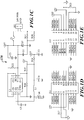
- the VCC system 1 may include a power supply 120 ( Figure 1C ) to provide a stable on-board 5V supply, for example from an input voltage of about 8V to 20V.
- the power supply 120 may, for example, include a peak boost/buck/inverting switching regulator, for instance an MC33063A switching regulator commercially available from Texas Instruments.
- the power supply may include a 7805 voltage regulator. Current consumption may be less than 0.2A.
- a battery-backed power supply (not shown) may be provided on a separate board, which provides a capability to manage temporary low input periods without configuration restart, is self powered from generator output, and if +24V, is nominal for industrial controller standards compatibility.
- Another suitable power supply could be one that accepts a +24VDC nominal input and provides a +5VDC 0.25A output, which is an industrial controller standard that provides +40V input voltage range.
- the VCC system 1 may include an RS485 serial interface 110 ( Figure 2E ).
- RS485 serial interface 110 may be a common, standard, industrial control bus used for digital control of coil configuration as well as status reporting from the VCC system 1.
- RS485 serial interface 110 provides some noise immunity, which is useful to address ground noise issues which may be common in high power installations.
- the serial format used may be the common 9600 baud, 8bit, 1 stop bit, no parity.
- Firmware may be updated via serial interface U6.
- Figure 5 shows method 500 of operation of the VCC system 1, according to one illustrated embodiment.
- the VCC 1 system typically starts with the coils in a default parallel pattern, arrangement or configuration. Current is generated as output from the coils to the bridge rectifiers 10.
- the controller 90 sends switching commands to triacs 30 and/or relays 50.
- triacs 30 e.g., Q1-Q5
- appropriate states e.g ., ON, OFF
- the controller 90 causes the relays 50 (e.g ., K1-K5) to change states after the triacs 30 have taken up the load.
- the triacs 30 cease carrying current flow at 510.
- bridge rectifiers 10 adjust diodes to isolate current at 512.
- bridge rectifiers 10 may isolate coils on occurrence of various conditions such as an open circuit, low voltage or electrical short conditions.
- a VCC system 1 may retain the single-phase circuit configuration, with a three-phase implementation created with three separate circuits. This has various advantages, including simplifying the individual phase circuits, providing the required phase isolation, easing construction of the combined circuit, and also allowing poly-phase implementations.
- a coil step control may be included for overvoltage protection. This may have a manual or automatic control to prevent overvoltage output and protect the circuit elements.
- a voltage output monitor may be present for fault detection.
- the VCC system 1 provides redundancy, in that if a coil fails (either short or open), the action of the associated bridge rectifier 10 is to isolate that coil from the rest of the circuit, while the rest of the circuit operates normally. Note that any coils connected in series modes with the failed coil will also be isolated in such a case, but will re-connect to the circuit if the VCC system 1 disconnects those coils from the failed coil (as long as the reconnection is of equivalent series connection level to the rest of the coils).
- each induction element is connected to a VCC system 1
- a methodology for containing the wiring outputs of each stack independently may be used.
- this design has all wires from each stack treated independently such that there is a dedicated VCC system 1a (only one identified by broken line and called out in Figure 4 ) for each stator, or stator pair (that may be employed when a double sided stator is used).
- the wiring from each stack that is directed to the VCC system 1a will be managed by respective controller 90.
- each VCC unit (each stack) is then rectified to a single DC output such that only a common DC bus BUS-, BUS+ is required for connecting a multitude of independent machine stacks.
- This common DC bus BUS-, BUS+ may significantly reduce the need for tracking the wiring coming from each stack of the generator, may reduce the labor requirements in manufacture, may reduce the wiring cost (as less wire is needed), and may reduce the electrical losses that would otherwise result should that additional wire be used.
- this manufacturing methodology lends itself well to a modular construction that allows easy customization for various generator designs.
- a generator design might have a rated output of 500kW for each independent stator.
- For a two stator stack electric machine it would be a one megawatt machine design, for a four stack machine, a 2 MW machine design and so on, so that independent single stacks can be mated together easily and connected to a common DC bus.
- This modular design may allow a single set of components, required for a single stack, to be employed in such a way as to make a multitude of different sized machines, thereby reducing manufacturing costs.
- a "motor mode" operation for the generator may be employed to obviate the need for a clutch.
- This circuit can operate by applying voltage from the bus 'output' to one or more of the coils of the electric machine to run the electric machine it as a motor instead of as a generator.
- This operation 'spins up' (using active stages) the unloaded stages in a multi-stack electric machine from the DC bus power, but also may be used in other applications.
- such may be used in electric vehicles where the primary mode of the electric machine is as a motor, but the electric machine also operates in a 'regenerative braking' generator mode.
- Such fits well with a VCC system configured with switches on all bridge rectifiers. When a new stage begins, with low energy production, the new stage is isolated from the bus by bridge rectifiers 10.
- the output voltage may be returned to AC from the rectified DC.
- Switches triac 30, solid state relays 50, or other switches fast enough and with AC capability
- the output AC waveform will have a small 'zero-cross dead-zone distortion' due to voltage drops in the bridge rectifiers 10 and DC to AC switch bridge, but the waveform would be suitable for connection to a transformer or motor.
- This method is synchronous with the input AC waveform, whereas the 'reversible VCC' configuration for stack spin-up described previously pulse-width modulates (PWM) an AC waveform that is independent of the generator output frequency, as it operates from a relatively constant-voltage filtered DC bus input rather than an unfiltered DC rectified waveform.
- PWM pulse-width modulates
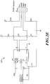
- Figure 3 shows two 2-coil electric machines (e.g ., generators, motors) linked to a common bus using respective VCC systems 140, 145.
- This arrangement can be expanded to a number of coils on each VCC system 140, 145, and a number of VCC units connected to the common bus output point.
Description
- This application generally relates to electric machines with coils or windings (e.g., generators, motors), and more particularly to systems, apparatus and methods that configure coils or windings of multistage electric machines.
- For conventional fluid-flow electrical-generation turbine systems, such as wind turbine systems, in which the energy source is variable (i.e., the fluid speed and/or the rate of flow of the fluid varies over time), the amount of energy captured from the energy source may only be a fraction of the total of the capturable energy. For example, in a typical wind farm, that fraction may be one half, or less of the total capturable energy.
- The power flow though a variable-speed conventional turbine/generator/transformer system is restricted in the range of power that can be output, i.e., from a minimum output power to a rated output power, due to limitations of the generator, the power converter (if present), and/or the output transformer used within the system. This restriction arises because conventional electromagnetic generators have reduced efficiency at lower power levels, as does the power converter (if present) and particularly the transformer that couples power to the electrical load. As a result, for conventional variable-speed turbine/generator/transformer systems an engineering design decision is usually made to limit the power rating of the generator (and any associated power converter, power conditioner or power filter, if present) and the associated output transformer so as to optimize efficiency over a restricted range of power. Therefore, at the extremes of normal-operating fluid speeds, i.e., at a low fluid speed and especially at a high fluid speed, less power is coupled into the turbine than is otherwise possible to extract from the fluid energy source. For a given design of turbine diameter, and possibly axial length, this translates, over time, into less energy capture than the turbine may be capable of transmitting to the generator.
- To increase energy capture in situations in which the energy source has a variable speed of fluid driving the turbine, and in which the turbine may have a variable speed of rotation, a multi-stage generator may be used in the turbine system. A multi-stage generator is an electric machine operating as an electrical generator that takes mechanical energy from a prime mover and generates electrical energy, usually in the form of alternating current (AC) power. Such a multi-stage generator is disclosed in
US Patent No. 7081696 andU.S. Patent Application Publication No. 2008088200 . An advantage of a multi-stage generator over a conventional generator is that a multi-stage generator can be dynamically sized depending on the power output of the turbine. A conventional generator is effective at capturing energy from the energy source over a limited range of fluid speeds, whereas a multi-stage generator is able to capture energy over an extended range of fluid speeds of the energy source, due to staged power characteristics. - The electrical power that is generated from a multi-stage generator is variable in nature, meaning the output power waveforms produced may vary from time to time, for example in: voltage amplitude; current amplitude; phase; and/or frequency. Additionally a multi-stage generator may include a plurality of induction elements, each of which generates its own power waveform, which may differ in voltage amplitude, current amplitude, phase, and/or frequency, from that generated by other induction elements within the generator. An electrical load such as an electric utility power grid may not be capable of directly consuming the electrical power that is generated by a multi-stage generator, as the power generated may not be in a suitable form, for example with respect to waveform shape as a function of time, voltage amplitude, current amplitude, phase, and/or frequency, as may be required by the electrical load. An electrical load such as a utility power grid typically expects from a turbine electrical generation system a single-phase, or split-phase, or 3-phase voltage or current waveform that is usually sinusoidal, and relatively stable. However, a multi-stage generator typically generates varying waveforms.
- Past attempts to maintain a consistent output range voltage from such generators have required either the linking together of multiple generators, each optimized for a particular input range, or complex switching networks. These solutions are costly and complex, which in turn, makes them less reliable and limits the available switching range.
-
U.S. Patent 3,984,750 is directed to an alternator-rectifier unit in which separate three-phase windings are connected to individual rectifiers arranged for series-parallel switching to improve current-voltage characteristics. Notably, such employs switching on the direct current (DC) side of the rectifier. Such circuit is associated with relatively high losses, experiencing four diode voltage drops. Such is not extended beyond a single coil configuration switch. -
U.S. Patent Application No. 2007/0182273 describes circuitry for configuring generator coils in various series/parallel combinations. This disclosure has 4 coils configured using 14 switches. Each switch carries multiple coil loads, up to full section current in parallel case. The system uses 12 switches in circuit for a series case, and up to 10 switches in circuit in parallel case. - The concept of independent induction elements and the ability to electrically configure such elements in various configurations offers benefits, however, manufacture of such a design may be challenging and expensive. If the wiring outputs of the machine's induction elements are independently run to a common configuration controller, the numbers of wires could become unmanageable. For example, if the generator had 50 coils per stack (i.e., 50 induction elements) that would result in 100 wires connecting to each stack. For a six stack machine, 600 wires would be used, that must all be properly connected to the appropriate contacts on a single configuration controller. It would be highly challenging to track the wires during assembly, and there are numerous other challenges that result.
-
DE19733208 describes a he circuit arrangement that is used for a vehicle three-phase generator or alternator. The winding of the machine is made up of two partial windings (1,2). The voltages and currents at the outputs of the two partial coils are rectified. The outputs of one partial coil are connected to the inputs of a first rectifier (15). The outputs of the other half-winding (2) are connected to the inputs of another rectifier (16). Both half coils are wound in the same direction and have the same connections. Each output of one half winding (1) is connected via the circuit of two switchable elements with two outputs of the other half winding (2). Thus when the switch line is connected through the two half windings are electrically connected in series. -
US2006/273766 describes a high-power permanent-magnet generator in which a stator winding is divided into a first winding part and second winding parts to keep a number of turns less, and capacitors are installed between any different phases to store a current therein to raise a voltage and thereby yielding a high output.WO8807782 -
WO2007098227 describes a power tool having an electronically commutated DC motor capable of providing various operating modes ranging from a maximum efficiency operating mode to a maximum power operating mode. - Document
WO 98/08291 A1 - Accordingly there is provided a system and method in accordance with the independent claims. Advantageous features are in the dependent claims.
- Embodiments of the present system and method include a variable configuration controller (referred to as a "VCC") system and method to connect multiple generator coil windings in varying series or parallel combinations to maintain a relatively consistent output voltage (for example, within a 2:1 range) in response to varying input shaft speeds. The VCC may be used with various electric machines, for instance single or multi-phase generators, and provides a rectified DC output from each AC phase input from an induction element. The DC output may optionally be used with a Power Factor Correction ("PFC") circuit to increase the efficiency of generator operation by smoothing the current wave shape to a near sinusoid.
- The systems, apparatus and methods allow the configuration of multiple coils or windings in variable series/parallel combinations. The systems, apparatus and methods may also allow switching series and parallel coils or windings in tandem with rectification, rather than switching on the DC side, post-rectification. This may be accomplished using fewer switches than in previously described systems. In fact, parallel configuration can be achieved with no switches or with the switches open. The VCC system advantageously employs AC-side parallel/series switching, combined with AC/DC rectification, and DC/DC blocking capabilities of the bridge rectifiers. While the AC side switches (e.g., relay, IGBT, SSR, or any other switch) perform part of the switching action, the diode rectifier bridges perform series combination, isolation of intermediate step points , and connection of the appropriate coil terminals, and only those terminals, to the output. Thus, the diode rectifier bridges allow not only AC-DC rectification, but parallel current sharing, intermediate step isolation, and conduction of the 'end point' terminals to the DC bus output.
- The VCC system described herein avoids the high losses associated with other devices. For example, the VCC system produces only two diode drops no matter how many series/parallel coils are used or configured, compared to four diode drops of the device described in
U.S. patent 3,984,750 . - The VCC system described herein also employs a relatively simple switching scheme. Such advantageously avoids the complex switching scheme using a large number of switches, and associated losses, such as that described in
U.S. Patent Application Publication No. 2007/0182273 . That device uses 4 to 12 series switch elements for four coils, in contrast to the 1:1 ratio achievable using the VCC system described herein. Additionally, device of theU.S. Patent Application Publication No. 2007/0182273 requires the switch contacts to carry the parallel current of all coils. In contrast, VCC system described herein requires the switch contacts to carry the series current of only one coil per switch. This is a significant advantage since such reduces power losses, as well as allowing use of lower rated switches. - Even further, the VCC system described herein provides some inherent fault tolerance against both open and shorted coils. For example, if a given coil is short-circuited, or has a lower output voltage than other coils, the diode bridge rectifiers will isolate that coil from parallel combination. In the case that the shorted coil is series combined with other coils, the whole string may be isolated from the output if there are other series-parallel circuits or the output voltage may be reduced if there is only one series coil string (i.e., all coils series mode). Importantly, in no case is the output loaded down by the shorted coil, as would occur in AC-side switching type devices described in
U.S. Patent Application Publication No. 2007/0182273 . Also for example, if a given coil is open-circuited, the diode bridge rectifiers will isolate that coil from parallel combination. In the case that the open coil is series combined with other coils, the whole string containing the open coil will be isolated from the output. - When used, a dual-element TRIAC/relay switch combination provides further advantages. In particular, fast switching of the semiconductor element (e.g., TRIAC, or IGBT, or FET, or SSR) allows zero-cross switching. This controls transients and extends switch life. Meanwhile, low power loss of relay contacts means significantly higher switching efficiency of the VCC system. This combination adds additional cost and complexity, but the VCC system is unique in requiring as few as a single (i.e., one) switch element per coil and only requiring the switch carry the series current for that coil only. Hence, this extra cost and complexity is acceptable.
- Further, the VCC system may advantageously employ a common heat exchange structure (e.g., heat sink) for all diode bridge rectifiers in a given VCC. Such may facilitate maintaining equal current sharing among coils in parallel. In particular, a common heat exchange structure maintains an approximately equal temperature of all diodes so that their forward voltage drop also remains equal. This equal forward voltage drop helps maintain equal current sharing.
- In the drawings, identical reference numbers identify similar elements or acts. The sizes and relative positions of elements in the drawings are not necessarily drawn to scale. For example, the shapes of various elements and angles are not drawn to scale, and some of these elements are arbitrarily enlarged and positioned to improve drawing legibility. Further, the particular shapes of the elements as drawn are not intended to convey any information regarding the actual shape of the particular elements, and have been solely selected for ease of recognition in the drawings. The various embodiments are illustrated by way of example and not by way of limitation in the accompanying Figures.
-
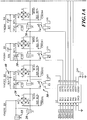
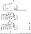
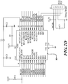
Figures 1A-1H are a schematic circuit diagram showing power circuits of a variable configuration controller system according to one illustrated embodiment, including a plurality of bridge rectifiers, a first number of switches in the form of triacs and a second number of switches in the form of relays connected in parallel with the triacs between respective pairs of coils, and an associated sixth switch circuit for coupling to another circuit board in a modular fashion. -
Figure 2A-2F are a schematic circuit diagram showing a partial representation of control circuit for a variable configuration controller system according to another illustrated embodiment. -
Figure 3 is a schematic circuit diagram showing two 2-coil variable configuration controller systems configured to output to a common load, according to one illustrated embodiment. -
Figure 4 is a top plan, partially broken, view showing a circuit board and a heat sink and illustrating a physical layout of various element of the variable configuration controller system on a circuit board, according to one illustrated embodiment. -
Figure 5 is a flow diagram showing a method of operating a variable configuration controller system to accomplish series/parallel switching and rectification, according to one illustrated embodiment. - In the following description, certain specific details are set forth in order to provide a thorough understanding of various disclosed embodiments. However, one skilled in the relevant art will recognize that embodiments may be practiced without one or more of these specific details, or with other methods, components, materials, etc. In other instances, well-known structures associated with electric machines (e.g., generators, motors), control systems, and/or power conversion systems (e.g., converters, inverters, rectifiers) have not been shown or described in detail to avoid unnecessarily obscuring descriptions of the embodiments.
- Unless the context requires otherwise, throughout the specification and claims which follow, the word "comprise" and variations thereof, such as, "comprises" and "comprising" are to be construed in an open, inclusive sense, that is as "including, but not limited to."
- Reference throughout this specification to "one embodiment" or "an embodiment" means that a particular feature, structure or characteristic described in connection with the embodiment is included in at least one embodiment. Thus, the appearances of the phrases "in one embodiment" or "in an embodiment" in various places throughout this specification are not necessarily all referring to the same embodiment. Furthermore, the particular features, structures, or characteristics may be combined in any suitable manner in one or more embodiments.
- As used in this specification and the appended claims, the singular forms "a," "an," and "the" include plural referents unless the content clearly dictates otherwise. It should also be noted that the term "or" is generally employed in its sense including "and/or" unless the content clearly dictates otherwise.
- The headings and Abstract of the Disclosure provided herein are for convenience only and do not interpret the scope or meaning of the embodiments.
- In the Figures, the following circuit elements are identified by the corresponding reference numbers:
VCC System 1 Bridge rectifiers D1-D5, collectively 10 Coil connector blocks J1-J6, collectively 20 Semiconductor switches, e.g. Triacs Q1-Q5, collectively 30 Snubber network 40 Relay 50 Expansion port 55 Gate drive 70 DC bus output connection 80 Controller 90 Analog multiplexer 100 RS485 interface 110 Power source 120 Amplifiers 130 Heat sink 140 - A VCC system 1 (
Figures 1A-1H ,2A-2F ) is a power electronics system configured to adjust multiple induction elements, such as coil windings of an electric machine (e.g., generator, electric motor), in various series and parallel combinations to maintain a relatively constant output voltage in response to varying input shaft speeds. The electric machine may use permanent magnets, electromagnets, a hybrid, and be core or coreless. AVCC system 1 may be used with a multi-phase electric machine, although each phase is managed in isolation by a separate circuit embodiment. AVCC system 1 can provide rectified DC output from each AC phase input, where theVCC system 1 is primarily intended for use with a subsequent Power Factor Correction (PFC) circuit. However, aVCC system 1 may also be used without PFC on the DC outputs. AVCC system 1 could be used with a PFC at the DC output, or a non-PFC with a single DC output. An alternative embodiment of aVCC system 1 could output AC. - The
VCC system 1 may operate using a number of devices or elements separately or in cooperation to connect the coils in the electric machine electrically in series and/or parallel. These devices or elements may include triacs, relays (e.g., solid state relays), bridge rectifiers, transistors and combinations thereof. The series coil configuration can be achieved by connecting the top side of one coil winding to the bottom side of the next coil winding by any suitable means. - A
VCC system 1 may work in conjunction with a power conversion system, such as the power conversion system and method described inU.S. Provisional Patent Application No. 60/094,007 . -
Figure 1 shows a VCC system 1a, according to one illustrated embodiment. The VCC system 1a includes a plurality of bridge rectifiers D1-D6 (collectively 10). Eachbridge rectifier 10 corresponds to a coil, from whichbridge rectifier 10 is electrically coupled to receive AC input. The coils may be connected by suitable connectors J1-J6 (collectively 20). In a six coil embodiment, sixbridge rectifiers 10 may be present, as illustrated inFigures 1A and1B .Bridge rectifiers 10 may provide several functions for the VCC system 1a, including: - 1. AC to DC conversion (i.e., rectification). AC to DC conversion is needed if a subsequent PFC circuit is used.
- 2. Coil series and parallel switching using diode biasing. When the coils are connected together in series, different diodes within
bridge rectifier 10 conduct in an appropriate configuration and can therefore isolate coils from the bus and thereby prevent coils shorting to the wrong side of bus. Thereforebridge rectifier 10 acts as switch in conjunction with a series switch, such as a semiconductor type switch (e.g., triode for alternating current (triacs), insulated gate bipolar transistors (IGBTs), field effect transistors (FETs), or solid state relays (SSR)) Q1-Q5 (collectively 30) or relay K1-K5 (collectively 50). - 3. Coil current sharing in conjunction with coil resistances.
Bridge rectifiers 10 initially maintain the coils in parallel. If the coil voltages are approximately equal, the current is shared between the coils to the outputs. If one coil has a higher voltage than the others, that coil then provides all of the current to the output, and the coils having lower voltages are isolated from the output. Given that the coils will not have precisely the same voltages, the load current sharing between coils can be maintained if they have approximately equal resistances. - In one implementation of the VCC system 1a, 1b,
bridge rectifiers 10 may be GBU8U devices, each capable of 8A, 600V operation. Such requires an adequate heat sink. In six parallel coil mode, a maximum output power of 420V RMS (600VDC peak) at 48A RMS (6 x 8A), or 20.2kW is possible. If only six coils are present, the six parallel coil mode represents the maximum output power possible from the VCC system 1a. At 220V RMS, 48A RMS, the maximum output in six parallel coil mode is 10.6kW (per phase). - The
bridge rectifiers 10 are therefore involved in providing the coil series and parallel switching function. Thebridge rectifiers 10 also convert the AC current to DC current for receipt by a DC bus for transmission to an electrical load. Also, if a coil has an internal short, its lower output voltage causes thebridge rectifier 10 to which it is connected to be reverse biased, automatically isolating that coil from the output circuit. Likewise, while all coils are normally active, should a coil be switched off, theappropriate bridge rectifier 10 will automatically isolate that coil from the output circuit. - If three parallel coil mode is selected as a nominal operating point based on a prime mover and/or load requirement, the six parallel coil mode can be used for over-speed or over-torque operation for peak load handling. In this case, the operating point current at the nominal operating point should be lowered from 8A to allow higher currents at peak load to be within the bridge diode ratings. If 6A is chosen for the nominal operational level, the nominal power at 220V is then 220V x 6A RMS x 3 = 3.96kW per phase. Thus
bridge rectifiers 10 diode ratings may be at least 15A. - Active switches (not shown) may be placed across one or more of
bridge rectifiers 10. These switches may be FETs, IGBTs, bipolar transistors, or any other suitable DC switching devices with high speed operation. These switches may be pulse-width modulated (PWM) to apply a variable DC voltage from the output bus to the coil connector blocks 20, thereby capable of reversing or changing the operation of the generator to that of a speed-controlled motor. In particular, the switches (not shown) may reverse current flow from the DC bus to the coils of the electric machine at appropriate times in order to provide a rotating magnetic field suitable for motor operation. - The semiconductor switches 30 may take a variety of forms, for example triacs, IGBTs, FETs, SSRs. Triacs are a bidirectional electronic switches for AC current that conducts current in either direction. The triac conducts and latches (i.e., stays ON) until the current load is removed, which for example may occur at zero crossing or a minimal level of current.
- As illustrated in
Figure 1 , fivesemiconductor switches 30 such as triacs, individually labeled as Q1 through Q5, may be used to control six coils of an electric machine. These triacs Q1-Q5 can be individually controlled by controller 90 (Figure 2D ) to enable series and parallel coil combinations in a six coil machine as follows: - 1. Six parallel coils: All triacs Q1-Q5 are OFF.
- 2. Three parallel coils, two series coils in each: triacs Q1, Q3, Q5 are ON; triacs Q2 and Q4 are OFF.
- 3. Two parallel coils, three series coils in each: triacs Q1, Q2, Q4, and Q5 are ON, triac Q3 is OFF.
- 4. Four series coils: either Q1, Q2, Q3; or Q2, Q3, Q4 or Q3, Q4, Q5 are ON. The other triacs are OFF.
- 5. Five series coils: triacs Q1, Q2, Q3, Q4; or triacs Q2, Q3, Q4, Q5 are ON. The other triac is OFF.
- 6. Six series coils: triacs Q1, Q2, Q3, Q4, Q5 (all triacs) are ON.
- Coil series configuration controlled by
triacs 30 provides enhanced operation due to lower current waveform distortion achieved by 'zero cross switching' oftriac 30, i.e., when the AC current waveform drawn from the switched coil is at its minimum value. - The
VCC system 1 may also include a number of relay switches 50, which may operate independently, or in conjunction withtriacs 30. For example, the VCC system illustrated inFigure 1 includes five relay switches, individually labeled K1-K5, each electrically in parallel with a respective one of the triacs Q1-Q5. Relay switches 50 provide for a low level of losses when switching, but are slow to switch (i.e., change state) in reaction to a switch command.Triacs 30 react to switch commands quickly but have higher losses when compared to relay switches 50. Thus, using bothtriacs 30 and relay switches 50 advantageously allows a multi-step switching process to be used. Theappropriate triac 30 reacts first and switches state accordingly. Then, the correspondingrelay switch 50 switches or changes state, taking over the load. The correspondingtriac 30 is disengaged for this purpose, until the next switching or change takes place. - The
VCC system 1 may employ a number of box headers (e.g., 10x2) J11 (Figure 1D ), J12 (Figure 1E ) to provide selectively detachable communicative coupling between a controller 90 (Figure 2D ) and various other VCC system elements, for example the triacs Q1-Q5 (Figures 1A ,1B ) and relays K1-K5 (Figures 1A ,1B ). - Respective
gate drive circuits 70a-70f (Figure 1H , collectively 70) are repeated at each zero cross to ensuretriac 30 "ON" control. Changingtriac 30 drive signals G Q1-G Q5 only at zero cross also prevents unintended series configurations (the zero cross detection ensures alltriacs 30 except those with a gate drive are "OFF"). The zero cross detection circuits may use A/D conversion of both voltage and current inputs, and a digital filter for averaging and zero cross estimation to increase robustness and frequency range. Zero crossing detection may be performed in digital signal processing in controller 90 (e.g., U101,Figure 2D ) by measuring voltages VMON1- VMON6 and currents CMON1-CMON 6 through multiplexers 100 (e.g., U4, U5,Figures 2A and2B ), signal amplifiers 130 (Figures 2A and2B ) and buffers U7 (Figures 2A ,2B ), and the processor internal A/D converter within controller 90 (e.g., U101,Figure 2D ). - A current monitor circuit may be present for zero cross detection. The current monitor circuit could be used for zero cross trigger switching of
triacs 30. In particular, current monitoring resistors R49-R54 (Figures 1A and1B ) present a voltage drop proportional to current flow in each coil, selected by multiplexers 100 (e.g., U4, U5,Figures 2A and2B ), amplified byamplifiers 130, and converted to digital representation by an A/D converter within controller 90 (e.g., U101,Figure 2D ). - Within the 100 Ohm and 0.1uF networks, across each
triac 30 are snubber networks 40 (only one called out inFigure 1A andFigure 4 ). Thesnubber networks 40 absorb voltage transients which otherwise might cause false triggers oftriacs 30 at turn-OFF or zero-cross points.Snubber network 40 may use a carbon-composition resistor that has high pulse handling capabilities (many kW for short pulses), but is only 1/2W continuous rated. The 100ohm 0.1uF combination may be limited to 110VAC at 1kHz or 220VAC at 500Hz due to continuous power dissipation in the snubber resistance. Higher voltage operation of theVCC system 1 requires lowering both the resistance and capacitance value. The snubber could be designed for greater voltage, e.g., a 47 ohm and 0.033uF snubber would allow for 500VAC at 1kHz. -
Bridge rectifiers 10, when connected to a load, may also act as snubbers for transient energy across the switching elements, whether those elements be triacs 30,relay contacts 50, or transistors. Such a configuration may eliminate the need for thesnubber network 40. Additionally, there aretriacs 30 available (for example those sold in association with the trademark ALTERNISTOR®), that do not requiresnubber networks 40. - Gate drive 70 circuits may include isolation transformers T1-T6 (
Figure 1H ), coupling capacitors (not shown), such as 0.47uF AC coupling capacitors, and coupling discharge resistances (not shown), typically 10k, coupled across a primary side of the isolation transformers T1-T6. The digital control output circuits are isolated from the high voltage at the triac gates by transformers T1-T6. In addition, a 2:1 winding ratio provides a 4:1 impedance transformation so thatcontroller 90 may supply up to the required 50mA triac gate drive level. 74HCT574 buffer/driver/level converter circuits U102, U103 (Figure 2C ) may be included within gate drive circuit 70 (Figure 1H ). These circuits U102, U103 isolate the gate drive circuit 70 power supply noise fromcontroller 90, allow a level convert to a 5V drive, and free input/output (I/O) pins. For example, these circuits U102, U103 may translate the 3.3 processor or controller 90 (e.g., U1,Figure 2D ) logic levels to 5V levels at higher current capacity suitable for driving relay drivers U2 of the power circuit board (i.e., VCC_PWR), LEDs D101-D104 (Figure 2F ) of the control circuit board (i.e., VCC_MCU), and triac transformers T1-T6 of the power circuit board (i.e., VCC_PWR). - Relay contacts may be added across the
triacs 30 to reduce loss, at the cost of additional complexity. Such contacts may be +24V coil, 10A SPST contacts. - An
expansion port 55 may be provided within theVCC system 1. For example, an extra triac Q6 and/or relay switch (as appropriate) K6 at one 'end' (either the 'top' or 'bottom' of the coil stack) allows connection to another VCC system module to expand the coil series switching capability. This 'switch'expansion port 55 may be coupled to the 'unswitched' side of the next VCC system module (i.e., the 'top' of one coil stack connected to the 'bottom' of the next coil stack). - As illustrated in
Figure 4 , theVCC system 1 may include a heat exchange structure (e.g., heat sink, heat spreader and/or heat pipe) 140. A variety of passive and/or active heat exchange structures may be used. Theheat exchange structure 140 can provide at least three functions. Theheat exchange structure 140 may remove heat frombridge rectifiers 10. Theheat exchange structure 140 may remove heat fromtriacs 30. Theheat exchange structure 140 may equalizebridge rectifier 10 temperatures, which may facilitate proper parallel mode current sharing betweenbridge rectifiers 10. - A relatively small
heat exchange structure 140 such as a small heat sink may be capable of less than 50W of dissipation, which is suitable for greater than 2kW of output power per phase. - Amplifiers 130 (
Figures 2A ,2B ) may provide differential amplification of the low-voltage current monitoring signal produced in the low-value (approximately 0.004 ohms) current shunt resistances formed by small lengths of wire or printed circuit board traces.Amplifiers 130 may have a differential gain of 100 and an output range of about 4V which results in a full scale current capability of about 10A. These amplifier circuits need not be precise due to variations in current shunt resistance values, but are intended to give representative current measurement results, which is useful for zero cross detection (digital signal processing mode), fault detection, and operational reporting. - The controller 90 (
Figure 2D ) may take a variety of forms. For example, thecontroller 90 may take the form of a microcontroller, microprocessor, application specific integrated circuit or programmable gate array. For instance, thecontroller 90 may take the form of a PIC16F883 microcontroller (U101). Thecontroller 90 is the core of theVCC system 1, controlling operation, providing a memory, a processor, A/D conversion, digital I/O, timing functions, as well as serial communications. A 20MHz clock crystal may result in 5MIPS instruction execution speed. Firmware may be programmed in approximately 1500 lines of assembly code. The microcontroller code may have a C source, which would improve portability and readability and increase the capability of theVCC system 1 to deal with more complex systems. -
Controller 90 may take the form of a higher performance device, for example a PIC18, which would provide faster processing (10+ MIPS), a hardware multiplier for signal processing, a faster A/D converter, and C code support, providing more memory and speed. - Root-Mean-Square (RMS) current and voltage measurements may be added to the code to support power and power factor (PF) reporting, allow zero cross detection at non-unity PF, provide fault detection support, measure input cycle frequency, and automatically adjust
triac 30 gate drive circuit 70 timeouts. - A daughterboard configuration could be used for
controller 90, which would allow the main power board (VCC_PWR) to have 3oz or 4oz copper, with associated large trace/space design rules and through-hole construction, while the controller board (VCC_MCU) can be standard 1oz copper with surface mount device (SMD) components and finer design rules. Thecontroller 90 or main power board (VCC_PWR) could each be re-designed separately and firmware updates could be handled by easy replacement of the module rather than the entire power circuit. - Analog multiplexers 100 (
Figures 2A ,2B ) may be added to select inputs to measure additional analog inputs tocontroller 90. For example, two 74HC4051 8-1 analog multiplexers may be added, which requires 15 analog inputs. Such may advantageously provide for a simpler layout and fewer connections to a controller daughterboard. - As previously noted, a
configuration expansion port 55 may be used, as seen inFigure 1B , wherein an extra relay K6 and/or triac Q6 on one end of the diode bridge string allows for the connection of two or more board units to larger coil configuration arrays via a connector J7. An associated controller connection between daughterboards would also be used for control synchronization. - The
CCV system 1 may include a first temperature sensor R17 (Figure 1D ) on the power board (VCC_PWR) to monitor temperature of or on the heat exchange structure (e.g., heat sink). , TheCCV system 1 may include a second temperature sensor R19 (Figure 2B ) on the control board (VCC_MCU) to monitor temperature in the ambient surroundings. Voltages across the temperature sensors R17, R19 represent temperature. These voltages are also multiplexed byanalog multiplexers 100, buffered by buffer U7, and converted by an AID converter within controller 90 (e.g., U101,Figure 2D ). - The
VCC system 1 may include a power supply 120 (Figure 1C ) to provide a stable on-board 5V supply, for example from an input voltage of about 8V to 20V. Thepower supply 120 may, for example, include a peak boost/buck/inverting switching regulator, for instance an MC33063A switching regulator commercially available from Texas Instruments. Also for example, the power supply may include a 7805 voltage regulator. Current consumption may be less than 0.2A. A battery-backed power supply (not shown) may be provided on a separate board, which provides a capability to manage temporary low input periods without configuration restart, is self powered from generator output, and if +24V, is nominal for industrial controller standards compatibility. Another suitable power supply could be one that accepts a +24VDC nominal input and provides a +5VDC 0.25A output, which is an industrial controller standard that provides +40V input voltage range. - The
VCC system 1 may include an RS485 serial interface 110 (Figure 2E ). RS485serial interface 110 may be a common, standard, industrial control bus used for digital control of coil configuration as well as status reporting from theVCC system 1. RS485serial interface 110 provides some noise immunity, which is useful to address ground noise issues which may be common in high power installations. The serial format used may be the common 9600 baud, 8bit, 1 stop bit, no parity. Firmware may be updated via serial interface U6. -
Figure 5 showsmethod 500 of operation of theVCC system 1, according to one illustrated embodiment. - At 502, the
VCC 1 system typically starts with the coils in a default parallel pattern, arrangement or configuration. Current is generated as output from the coils to thebridge rectifiers 10. - At 504, the
controller 90 sends switching commands totriacs 30 and/or relays 50. At 506, triacs 30 (e.g., Q1-Q5) are placed in appropriate states (e.g., ON, OFF) to arrange coils in a desired or commanded series/parallel arrangement. As noted previously, the triacs are relatively faster at switching than relays, but are associated with higher losses. Thus, at 508, thecontroller 90 causes the relays 50 (e.g., K1-K5) to change states after thetriacs 30 have taken up the load. Thus, thetriacs 30 cease carrying current flow at 510. - Optionally,
bridge rectifiers 10 adjust diodes to isolate current at 512. As previously noted,bridge rectifiers 10 may isolate coils on occurrence of various conditions such as an open circuit, low voltage or electrical short conditions. - At 514, series voltage switches through diodes and the coil voltage is applied to the DC bus as a series combination of voltages.
- Alternatively, a
VCC system 1 may retain the single-phase circuit configuration, with a three-phase implementation created with three separate circuits. This has various advantages, including simplifying the individual phase circuits, providing the required phase isolation, easing construction of the combined circuit, and also allowing poly-phase implementations. - A coil step control may be included for overvoltage protection. This may have a manual or automatic control to prevent overvoltage output and protect the circuit elements. A voltage output monitor may be present for fault detection.
- The
VCC system 1 provides redundancy, in that if a coil fails (either short or open), the action of the associatedbridge rectifier 10 is to isolate that coil from the rest of the circuit, while the rest of the circuit operates normally. Note that any coils connected in series modes with the failed coil will also be isolated in such a case, but will re-connect to the circuit if theVCC system 1 disconnects those coils from the failed coil (as long as the reconnection is of equivalent series connection level to the rest of the coils). - As a means to alleviate the manufacturing complexity of a multi-stage generator, wherein each induction element is connected to a
VCC system 1, a methodology for containing the wiring outputs of each stack independently may be used. As shown inFigure 4 , this design has all wires from each stack treated independently such that there is a dedicated VCC system 1a (only one identified by broken line and called out inFigure 4 ) for each stator, or stator pair (that may be employed when a double sided stator is used). The wiring from each stack that is directed to the VCC system 1a will be managed byrespective controller 90. The output of each VCC unit (each stack) is then rectified to a single DC output such that only a common DC bus BUS-, BUS+ is required for connecting a multitude of independent machine stacks. This common DC bus BUS-, BUS+ may significantly reduce the need for tracking the wiring coming from each stack of the generator, may reduce the labor requirements in manufacture, may reduce the wiring cost (as less wire is needed), and may reduce the electrical losses that would otherwise result should that additional wire be used. - In addition, this manufacturing methodology lends itself well to a modular construction that allows easy customization for various generator designs. For example, a generator design might have a rated output of 500kW for each independent stator. For a two stator stack electric machine, it would be a one megawatt machine design, for a four stack machine, a 2 MW machine design and so on, so that independent single stacks can be mated together easily and connected to a common DC bus. This modular design may allow a single set of components, required for a single stack, to be employed in such a way as to make a multitude of different sized machines, thereby reducing manufacturing costs.
- The sharing of load between stacks and VCC systems 1a as described above requires consideration of whether or not a PFC is present. If no PFC is present, coil current sharing depends on:
- a) Aligning generator phases (i.e., AC waveforms synchronized, mechanically aligned in the machine). The phases may be purposefully offset, but then there is phase switching due to rectifier action rather than current sharing between coils.
- (b) Matching coil phase winding resistances. This is obtained by equal size, same type (wire alloy), equal temperature, and equal length, of winding wire. Note that the length of wire may be minimized by positioning the VCC system at the generator housing making it easier to manage equal length wiring.
- (c) Using switching and rectifier elements within the VCC system that are matched types and that are maintained at the same temperature. Consistency in temperature may be obtained by using a common heat sink within the VCC system for the power components.
- (d) Using the same length and gauge of wiring from each VCC DC output connected to a common bus via a common connecting point.
- If a PFC circuit is present, coil current sharing is more actively controlled by the PFC circuit:
- (a) With the stack and VCC system, coil wire, phase, and semiconductor matching are still important as described above. Any stacks connected together before a common PFC circuit will generally require these same matching items for equal current sharing.
- (b) The PFC circuit actively controls the current drawn from each stack, and so may enforce sharing between multiple generator connections when multiple PFC circuits are used. Each PFC circuit controls the current level from the total of the units connected to it. The outputs of multiple PFC circuits may then be connected to a single DC output bus.
- (c) The sharing of current from multiple PFC circuits connected to a common bus depends upon those PFC circuits having a 'resistive style' output impedance and a controlled, accurate output voltage set point. The value of the resistive nature of the PFC circuit's output is chosen to manage voltage output differences, connection resistance variation, and ensure accurate PFC circuit output bus sharing. The resistance choice is a trade off between sharing level, losses, and bus voltage stability. Equal wire gauge and length from each PFC circuit output to a common bus point will enhance sharing and reduce the PFC circuit's resistance requirement.
- Alternatively, a "motor mode" operation for the generator may be employed to obviate the need for a clutch. This circuit can operate by applying voltage from the bus 'output' to one or more of the coils of the electric machine to run the electric machine it as a motor instead of as a generator. This operation 'spins up' (using active stages) the unloaded stages in a multi-stack electric machine from the DC bus power, but also may be used in other applications. For example, such may be used in electric vehicles where the primary mode of the electric machine is as a motor, but the electric machine also operates in a 'regenerative braking' generator mode. Such fits well with a VCC system configured with switches on all bridge rectifiers. When a new stage begins, with low energy production, the new stage is isolated from the bus by
bridge rectifiers 10. - Also the output voltage may be returned to AC from the rectified DC. Switches (
triac 30, solid state relays 50, or other switches fast enough and with AC capability) can be used as a bridge to reverse the output connections on alternate cycles of the rectified DC waveform, switching at zero voltage points. The output AC waveform will have a small 'zero-cross dead-zone distortion' due to voltage drops in thebridge rectifiers 10 and DC to AC switch bridge, but the waveform would be suitable for connection to a transformer or motor. - This method is synchronous with the input AC waveform, whereas the 'reversible VCC' configuration for stack spin-up described previously pulse-width modulates (PWM) an AC waveform that is independent of the generator output frequency, as it operates from a relatively constant-voltage filtered DC bus input rather than an unfiltered DC rectified waveform.
-
Figure 3 shows two 2-coil electric machines (e.g., generators, motors) linked to a common bus usingrespective VCC systems VCC system - The above description of illustrated embodiments, including what is described in the Abstract, is not intended to be exhaustive or to limit the embodiments to the precise forms disclosed. Although specific embodiments of and examples are described herein for illustrative purposes, various equivalent modifications can be made without departing from the spirit and scope of the disclosure, as will be recognized by those skilled in the relevant art. The teachings provided herein of the various embodiments can be applied to control systems for electric machines, not necessarily the exemplary variable coil configuration systems, methods, and apparatus generally described above.
- The various embodiments described above can be combined to provide further embodiments. All of the US patents, US patent application publications, US patent applications, foreign patents, foreign patent applications and non-patent publications referred to in this specification and/or listed in the Application Data Sheet, including but not limited to
US Patent No. 7,081,696 ;U.S. Patent Application Publication No. 2008088200 ;U.S. Provisional Patent Application No. 60/094,007, filed September 3, 2008 U.S. Provisional Patent Application Serial No. 61/239,769, filed September 3, 2009 - These and other changes can be made to the embodiments in light of the above-detailed description. In general, in the following claims, the terms used should not be construed to limit the claims to the specific embodiments disclosed in the specification and the claims. Accordingly, the claims are not limited by the disclosure.
Claims (12)
- A variable coil configuration system (1), comprising:a plurality of bridge rectifiers (10), the bridge rectifiers (10) each having a pair of AC nodes on an AC side of the respective bridge rectifier (10) and a pair of DC nodes on a DC side of the respective bridge rectifier (10), wherein the pair of AC nodes for each bridge rectifier in the plurality of bridge rectifiers is electrically connectable to a coil of an electric machine;a first number of switches (30), each of the switches of the first number of switches on the AC side of a respective one of the bridge rectifiers (10), wherein each of the bridge rectifiers is arranged to couple at least two coils electrically in parallel with one another when a respective switch of the first number of switches (30) is open and the at least two coils are not subject to an open circuit condition, a low voltage condition or a short circuit condition, and each of the switches of the first number of switches is operable to selectively electrically couple the at least two coils electrically in series with one another when the switch (30) is closed;characterized by a controller configured to switch the first number of switches (30) at respective zero crossings of a respective current, wherein the first number of switches (30) are TRIACS; anda second number of switches (50), each of the switches of the second number of switches electrically connected in parallel with respective ones of the first number of switches (30), wherein the switches of the first number of switches (30) are faster than the switches of the second number of switches (50) and the switches of the second number of switches have a lower associated electrical loss than an electrical loss associated with the switches of the first number of switches (30).
- The variable coil configuration system of claim 1 wherein the bridge rectifiers (10) are configured to automatically electrically isolate a respective one of the coils of an electric machine from a parallel combination with at least one other one of the coils of the electric machine when the respective one of the coils experiences either a short circuit condition, a low voltage condition or an open-circuit condition.
- The variable coil configuration system of claim 2 wherein the bridge rectifiers (10) are configured to automatically electrically couple the respective one of the coils of the electric machine in series with at least one other one of the coils of the electric machine when the respective one of the coils experiences either the short circuit condition or the low voltage condition.
- The variable coil configuration system of any of claims 1 through 3 wherein the second number of switches are mechanical switches.
- The variable coil configuration system of any of claims 1 through 3 wherein a number of active switches are selectively operable to reverse a current flow from a DC bus to the coils to operate the electric machine as a motor.
- The variable coil configuration system of any of claims 1 through 3, further comprising:an additional bridge rectifier coupled to an end of a string formed by the bridge rectifiers (10) of the first number of bridge rectifiers to couple the variable coil configuration electrically in parallel with a second variable coil configuration system;at least one additional switch operable to selectively couple the variable coil configuration electrically in series with the second variable coil configuration system; anda coupler configured to detachably electrically couple the second variable coil configuration system to the variable coil configuration system.
- The variable coil configuration system of any of claims 1 through 3 further comprising:a controller that, in operation is configured to cause switches of the first set of switches to close; andimmediately following the closing of one of the switches of the first set of switches, causes the one of the switches of the second set of switches that is electrically parallel with the switch of the first set of switches to close.
- A method of operating a variable coil configuration system (1) that comprises a plurality of bridge rectifiers (10), the bridge rectifiers (10) each having a pair of AC nodes on an AC side of the respective bridge rectifier and a pair of DC nodes on a DC side of the respective bridge rectifier and a first number of switches, each of the switches of the first number of switches on the AC side of a respective one of the bridge rectifiers, wherein each of the switches in the first number of switches is electrically connectable to at least two coils of an electric machine, the variable coil configuration system further comprising a second number of switches, each of the switches of the second number of switches on the AC side of a respective one of the bridge rectifiers and electrically connected in parallel with a respective one of the switches of the first number of switches, wherein the switches of the first number of switches are faster than the switches of the second number of switches and the switches of the second number of switches have a lower associated electrical loss than an electrical loss associated with the switches of the first number of switches, the method comprising:selectively coupling at least two coils of the electric machine electrically in parallel with one another via a respective one of the bridge rectifiers (10) when the switch connected to the at least two coils of the electric machine is open;selectively coupling at least two coils of the electric machine electrically in series with one another via a respective one of the first number of switches (30) when the switch connected to the at least two coils of the electric machine is closed;switching the switches at respective zero crossings of a respective current,wherein the first number of switches are TRIACS; andfor the coils of the electric machine that are electrically coupled in series with one another by the respective switch of the first number of switches, further coupling the coils of the electric machine electrically in series with one another by a respective one of the switches of the second number of switches immediately following the coupling electrically in series of the coils by the respective switch of the first number of switches.
- The method of claim 8 wherein selectively coupling at least two coils of the electric machine electrically in parallel with one another via a respective one of the bridge rectifiers (10) includes selectively coupling a first two coils electrically in parallel with one another at a first time and wherein selectively coupling at least one pair of coils of the electric machine electrically in series with one another via a respective one of the first number of switches (30) includes selectively coupling the first two coils electrically in series with one another at a second time, different from the first time.
- The method of claim 8 wherein selectively coupling at least two coils of the electric machine electrically in parallel with one another via a respective one of the bridge rectifiers includes selectively coupling a first two coils electrically in parallel with one another at a first time and wherein selectively coupling at least one pair of coils of the electric machine electrically in series with one another via a respective one of the first number of switches includes selectively coupling a second two coils, different from the first two coils, electrically in series with one another during the first time.
- The method of any of claims 8 through 10, further comprising:
automatically electrically isolating a respective one of the coils of the electric machine from a parallel combination with at least one other one of the coils of the electric machine by a respective one of the bridge rectifiers when the respective one of the coils experiences either a short circuit condition, a low voltage condition or an open-circuit condition. - The method of claim 11, further comprising:
automatically electrically coupling the respective one of the coils of the electric machine in series with at least one other one of the coils of the electric machine when the respective one of the coils experiences either the short circuit condition or the low voltage condition.
Applications Claiming Priority (2)
| Application Number | Priority Date | Filing Date | Title |
|---|---|---|---|
| US23976909P | 2009-09-03 | 2009-09-03 | |
| PCT/US2010/047750 WO2011028959A2 (en) | 2009-09-03 | 2010-09-02 | Variable coil configuration system, apparatus and method |
Publications (3)
| Publication Number | Publication Date |
|---|---|
| EP2474092A2 EP2474092A2 (en) | 2012-07-11 |
| EP2474092A4 EP2474092A4 (en) | 2015-05-13 |
| EP2474092B1 true EP2474092B1 (en) | 2020-04-29 |
Family
ID=43649973
Family Applications (1)
| Application Number | Title | Priority Date | Filing Date |
|---|---|---|---|
| EP10814529.3A Active EP2474092B1 (en) | 2009-09-03 | 2010-09-02 | Variable coil configuration system, apparatus and method |
Country Status (8)
| Country | Link |
|---|---|
| US (2) | US20120229060A1 (en) |
| EP (1) | EP2474092B1 (en) |
| CN (1) | CN102484448B (en) |
| BR (1) | BR112012004808A2 (en) |
| CA (1) | CA2773102C (en) |
| DK (1) | DK2474092T3 (en) |
| IN (1) | IN2012DN02566A (en) |
| WO (1) | WO2011028959A2 (en) |
Families Citing this family (26)
| Publication number | Priority date | Publication date | Assignee | Title |
|---|---|---|---|---|
| US20110241630A1 (en) | 2008-09-03 | 2011-10-06 | Exro Technologies Inc. | Power conversion system for a multi-stage generator |
| DK2474092T3 (en) * | 2009-09-03 | 2020-07-27 | Dpm Tech Inc | VARIABLE COIL CONFIGURATION SYSTEM, APPARATUS AND PROCEDURE |
| US8687341B2 (en) * | 2010-02-10 | 2014-04-01 | Hanchett Entry Systems, Inc. | Control circuit for electric unlocking devices using actuating solenoids |
| US9413217B2 (en) * | 2012-06-28 | 2016-08-09 | General Electric Company | Electromagnetic braking systems and methods |
| US9601918B2 (en) | 2012-06-28 | 2017-03-21 | General Electric Company | Systems and methods for controlling acceleration of a power generator |
| US10033314B2 (en) * | 2013-05-29 | 2018-07-24 | Magnelan Technologies Inc. | Modified Halbach array generator |
| RU2537955C1 (en) * | 2013-07-09 | 2015-01-10 | Федеральное государственное бюджетное образовательное учреждение высшего профессионального образования "Ульяновский государственный технический университет" | Device to start and compensate for reactive power of induction motor |
| JP6511908B2 (en) * | 2014-03-31 | 2019-05-15 | 大日本印刷株式会社 | Tension method of deposition mask, method of manufacturing deposition mask with frame, method of manufacturing organic semiconductor device, and tension device |
| US10797573B2 (en) * | 2014-04-16 | 2020-10-06 | Power It Perfect, Inc. | Axial motor/generator having multiple inline stators and rotors with stacked/layered permanent magnets, coils, and a controller |
| US10298104B2 (en) * | 2014-04-16 | 2019-05-21 | Power It Perfect, Inc. | Electrical motor and electrical generator device |
| AU2015286215B2 (en) | 2014-07-06 | 2020-02-06 | Giuliano Res | Cold start alternator |
| CN104810931A (en) * | 2015-03-30 | 2015-07-29 | 国家电网公司 | Induction pick power device and method thereof for power tracking |
| CN104979851B (en) * | 2015-07-03 | 2018-03-06 | 广东美的厨房电器制造有限公司 | A kind of on-off circuit and its control method |
| KR20170006590A (en) * | 2015-07-08 | 2017-01-18 | 삼성전기주식회사 | Power supply apparatus and method for controlling converter |
| US10355514B2 (en) | 2016-08-29 | 2019-07-16 | Apple Inc. | Rectifier arbitration in wireless charging systems |
| JP2020521418A (en) * | 2017-05-23 | 2020-07-16 | ディーピーエム テクノロジーズ インク. | Variable coil connection system |
| CN110892632B (en) * | 2017-08-04 | 2023-04-07 | 三菱电机株式会社 | Motor drive device and air conditioner |
| JP6945500B2 (en) * | 2018-06-11 | 2021-10-06 | 三菱電機株式会社 | Exciter |
| US10398004B1 (en) * | 2018-07-06 | 2019-08-27 | Elb Electronics, Inc. | LED fluorescent lamp emulator circuitry |
| US11722026B2 (en) | 2019-04-23 | 2023-08-08 | Dpm Technologies Inc. | Fault tolerant rotating electric machine |
| CN209709698U (en) * | 2019-04-26 | 2019-11-29 | 阳光电源股份有限公司 | A kind of inverter system |
| CN110764023B (en) * | 2019-09-18 | 2021-07-09 | 华为技术有限公司 | Rectifier chip and terminal equipment |
| CN111952035B (en) * | 2020-07-14 | 2022-03-08 | 中国科学院电工研究所 | Swinging magnetic field generating device and control method thereof |
| CA3217299A1 (en) | 2021-05-04 | 2022-11-10 | Tung Nguyen | Battery control systems and methods |
| CA3159864A1 (en) | 2021-05-13 | 2022-11-13 | Exro Technologies Inc. | Method and apparatus to drive coils of a multiphase electric machine |
| US11870302B2 (en) | 2021-08-20 | 2024-01-09 | Dana Automotive Systems Group, Llc | Systems and methods for a segmented electric motor |
Citations (2)
| Publication number | Priority date | Publication date | Assignee | Title |
|---|---|---|---|---|
| WO1998008291A1 (en) * | 1996-08-22 | 1998-02-26 | Rivera Nicholas N | Permanent magnet direct current (pmdc) machine with integral reconfigurable winding control |
| WO2000072433A1 (en) * | 1999-05-19 | 2000-11-30 | Kansai Research Institute | Switching circuit |
Family Cites Families (58)
| Publication number | Priority date | Publication date | Assignee | Title |
|---|---|---|---|---|
| US3593112A (en) * | 1969-12-22 | 1971-07-13 | Varo | Solid-state ac power control apparatus |
| US3663828A (en) * | 1970-10-20 | 1972-05-16 | Nasa | Failsafe multiple transformer circuit configuration |
| US3870928A (en) * | 1972-03-30 | 1975-03-11 | Melvin O Allen | Voltage monitoring system |
| DE2426956A1 (en) | 1974-06-04 | 1976-01-02 | Bosch Gmbh Robert | AC GENERATOR |
| US4159496A (en) * | 1977-09-22 | 1979-06-26 | Randam Electronics, Inc. | Safety device for hospital beds employing electric current |
| US4389691A (en) * | 1979-06-18 | 1983-06-21 | Power Management Corporation | Solid state arc suppression device |
| US4338557A (en) * | 1979-08-14 | 1982-07-06 | Wanlass Cravens Lamar | Variable speed electric machine having controlled magnetic flux density |
| US4394720A (en) * | 1980-12-10 | 1983-07-19 | Jean Frager | Auto-stabilized high power electric generator especially adapted for powering processes involving discharge in a rarefied gaseous atmosphere |
| US4639647A (en) * | 1984-04-04 | 1987-01-27 | Posma Bonne W | Four quadrant control of series motors |
| WO1986000689A2 (en) * | 1984-07-14 | 1986-01-30 | Alfred Eckerfeld | Electric hot water apparatus with output temperature regulation and electronic power regulating device |
| AU616885B2 (en) | 1987-03-24 | 1991-11-14 | John Van Der Wolf | Electric generator |
| US4948044A (en) * | 1989-08-21 | 1990-08-14 | Harper-Wyman Company | Electronic digital thermostat having an improved power supply |
| US5065305A (en) * | 1990-06-22 | 1991-11-12 | Arco Electric Products Corp. | Rotary phase converter having circuity for switching windings to provide reduced starting current with rapid, dependable starting |
| EP0489970A1 (en) * | 1990-12-14 | 1992-06-17 | BSG-Schalttechnik GmbH & Co. KG | Method and device for operating electric drives |
| US5610448A (en) * | 1994-07-25 | 1997-03-11 | International Energy Conservation Systems, Inc. | Universal switching device and method for lighting applications |
| US5699218A (en) * | 1996-01-02 | 1997-12-16 | Kadah; Andrew S. | Solid state/electromechanical hybrid relay |
| DE19733208C1 (en) | 1997-08-01 | 1998-10-15 | Daimler Benz Ag | Circuit arrangement for three=phase generator for motor vehicle |
| WO2000005652A1 (en) | 1998-07-24 | 2000-02-03 | Sun Microsystems, Inc. | Method and apparatus for achieving deterministic memory allocation response in a computer system |
| JP3921905B2 (en) * | 2000-01-17 | 2007-05-30 | スズキ株式会社 | Output structure of portable generator |
| US6528902B1 (en) * | 2000-03-07 | 2003-03-04 | Bits Ltd | Device for controlling power distribution to subsystems |
| US6501195B1 (en) * | 2000-06-21 | 2002-12-31 | Bits Ltd | Device for controlling power distribution to subsystems |
| FR2812476B1 (en) * | 2000-07-28 | 2002-10-31 | St Microelectronics Sa | ALTERNATIVE-CONTINUOUS CONVERTER |
| US6731019B2 (en) * | 2000-08-07 | 2004-05-04 | Ocean Power Technologies, Inc. | Apparatus and method for optimizing the power transfer produced by a wave energy converter (WEC) |
| DE10040273A1 (en) | 2000-08-14 | 2002-02-28 | Aloys Wobben | Wind turbine |
| IT1320621B1 (en) * | 2000-09-05 | 2003-12-10 | Wrap Spa | METHOD, SYSTEM AND APPARATUS FOR DATA TRANSMISSION ON THE ELECTRICITY NETWORK |
| IT1320622B1 (en) * | 2000-09-05 | 2003-12-10 | Wrap Spa | SYSTEM AND DEVICE FOR THE MONITORING OF AT LEAST ONE ELECTRIC HOUSEHOLD, IN PARTICULAR A HOUSEHOLD APPLIANCE. |
| US6455974B1 (en) | 2000-09-28 | 2002-09-24 | General Electric Company | Combined Delta-Wye armature winding for synchronous generators and method |
| DE10048146A1 (en) * | 2000-09-28 | 2002-04-11 | Philips Corp Intellectual Pty | Power supply for X-ray generator |
| DK175645B1 (en) | 2002-10-31 | 2005-01-03 | Bonus Energy As | Electric circuit for powered generator with segmented stator |
| US6992873B2 (en) * | 2003-03-05 | 2006-01-31 | Lewis Joseph S | Automated AC line filter and surge suppression apparatus and method |
| US7940506B2 (en) * | 2003-03-05 | 2011-05-10 | Dollar Energy Group, Inc. | Automated AC line filter and surge suppression apparatus and method |
| EP1467094B2 (en) | 2003-04-08 | 2017-03-01 | GE Energy Power Conversion GmbH | A wind turbine for producing electrical power and a method of operating the same |
| US7230522B2 (en) * | 2004-05-06 | 2007-06-12 | Stevens Carlile R | Power line communication device and method |
| US6969927B1 (en) * | 2004-06-25 | 2005-11-29 | Clipsal Asia Holdings Limited | Power switching apparatus |
| US7482708B1 (en) * | 2004-07-21 | 2009-01-27 | Bits Limited | Apparatus for controlling power distribution two subsystems |
| US7081696B2 (en) | 2004-08-12 | 2006-07-25 | Exro Technologies Inc. | Polyphasic multi-coil generator |
| US7602158B1 (en) * | 2005-03-21 | 2009-10-13 | National Semiconductor Corporation | Power circuit for generating non-isolated low voltage power in a standby condition |
| JP2006345592A (en) | 2005-06-07 | 2006-12-21 | Fuji Seratekku Kk | High output generator rotating at extremely low speed |
| US7439714B2 (en) | 2005-09-27 | 2008-10-21 | Gamesa Innovation & Technology, S.L. | Method for operation of a converter system |
| WO2007092621A2 (en) | 2006-02-09 | 2007-08-16 | Windera Power Systems, Inc. | Turbine with constant voltage and frequency output |
| KR20070082819A (en) * | 2006-02-18 | 2007-08-22 | 심영숙 | High efficient motor-generator |
| US7602137B2 (en) | 2006-02-20 | 2009-10-13 | Black & Decker Inc. | Electronically commutated motor and control system |
| JP4767176B2 (en) * | 2006-03-20 | 2011-09-07 | 東芝三菱電機産業システム株式会社 | Heating power supply |
| US7932480B2 (en) * | 2006-04-05 | 2011-04-26 | Mks Instruments, Inc. | Multiple heater control system with expandable modular functionality |
| US20080088200A1 (en) | 2006-06-08 | 2008-04-17 | Jonathan Ritchey | Poly-phasic multi-coil generator |
| US7348764B2 (en) * | 2006-07-13 | 2008-03-25 | Ocean Power Technologies, Inc. | Coil switching of an electric generator |
| EP1879280B1 (en) | 2006-07-14 | 2014-03-05 | OpenHydro Group Limited | A hydroelectric turbine |
| US7977842B2 (en) | 2006-10-05 | 2011-07-12 | Lin Panchien | Adaptive winding system and control method for electric machines |
| US7710081B2 (en) | 2006-10-27 | 2010-05-04 | Direct Drive Systems, Inc. | Electromechanical energy conversion systems |
| FI119086B (en) | 2006-11-06 | 2008-07-15 | Abb Oy | Method and arrangement for a wind turbine |
| ES2325844B1 (en) | 2007-03-30 | 2010-06-25 | GAMESA INNOVATION & TECHNOLOGY, S.L. | GENERATOR FOR WIND TURBINE WITH INDEPENDENT WINDINGS. |
| US20080266742A1 (en) * | 2007-04-30 | 2008-10-30 | Watlow Electric Manufacturing Company | Apparatus and method for increasing switching life of electromechanical contacts in a hybrid power switching device |
| DE502008001253D1 (en) | 2008-02-27 | 2010-10-14 | Abb Schweiz Ag | Energy system comprising a wind or hydropower turbine |
| US7554303B1 (en) * | 2008-05-15 | 2009-06-30 | Hideo Kawamura | Controller of permanent magnet generator |
| US8279640B2 (en) * | 2008-09-24 | 2012-10-02 | Teco-Westinghouse Motor Company | Modular multi-pulse transformer rectifier for use in symmetric multi-level power converter |
| US8138620B2 (en) | 2009-06-12 | 2012-03-20 | General Electric Company | Methods and systems for operating a wind turbine power converter |
| DK2474092T3 (en) * | 2009-09-03 | 2020-07-27 | Dpm Tech Inc | VARIABLE COIL CONFIGURATION SYSTEM, APPARATUS AND PROCEDURE |
| CN102714084B (en) * | 2009-10-12 | 2015-12-02 | 意法爱立信(法国)有限公司 | There is the integrated transformer of multiple transformation ratio |
-
2010
- 2010-09-02 DK DK10814529.3T patent/DK2474092T3/en active
- 2010-09-02 EP EP10814529.3A patent/EP2474092B1/en active Active
- 2010-09-02 CN CN201080039251.0A patent/CN102484448B/en active Active
- 2010-09-02 US US13/393,749 patent/US20120229060A1/en not_active Abandoned
- 2010-09-02 WO PCT/US2010/047750 patent/WO2011028959A2/en active Application Filing
- 2010-09-02 IN IN2566DEN2012 patent/IN2012DN02566A/en unknown
- 2010-09-02 BR BR112012004808A patent/BR112012004808A2/en not_active IP Right Cessation
- 2010-09-02 CA CA2773102A patent/CA2773102C/en active Active
-
2014
- 2014-06-03 US US14/295,069 patent/US9812981B2/en active Active
Patent Citations (2)
| Publication number | Priority date | Publication date | Assignee | Title |
|---|---|---|---|---|
| WO1998008291A1 (en) * | 1996-08-22 | 1998-02-26 | Rivera Nicholas N | Permanent magnet direct current (pmdc) machine with integral reconfigurable winding control |
| WO2000072433A1 (en) * | 1999-05-19 | 2000-11-30 | Kansai Research Institute | Switching circuit |
Also Published As
| Publication number | Publication date |
|---|---|
| US9812981B2 (en) | 2017-11-07 |
| BR112012004808A2 (en) | 2018-03-13 |
| US20140347903A1 (en) | 2014-11-27 |
| EP2474092A2 (en) | 2012-07-11 |
| EP2474092A4 (en) | 2015-05-13 |
| WO2011028959A2 (en) | 2011-03-10 |
| CA2773102C (en) | 2018-01-23 |
| CA2773102A1 (en) | 2011-03-10 |
| CN102484448A (en) | 2012-05-30 |
| WO2011028959A3 (en) | 2011-07-14 |
| US20120229060A1 (en) | 2012-09-13 |
| CN102484448B (en) | 2015-06-17 |
| IN2012DN02566A (en) | 2015-08-28 |
| DK2474092T3 (en) | 2020-07-27 |
Similar Documents
| Publication | Publication Date | Title |
|---|---|---|
| EP2474092B1 (en) | Variable coil configuration system, apparatus and method | |
| CN101621207B (en) | Wind turbine with parallel converters utilizing a plurality of isolated transformer windings | |
| CN105576921B (en) | Dynamically reconfigurable motor, electric system and motor dynamics reconstructing method | |
| EP3034868B1 (en) | Systems and methods for increasing wind turbine power output | |
| EP3096005B1 (en) | Limit for derating scheme used in wind turbine control | |
| US20150349687A1 (en) | Electric Power Generation and Distribution for Islanded or Weakly-Connected Systems | |
| CN104145418A (en) | Air conditioner | |
| US20100133826A1 (en) | Method and apparatus for generating power in a wind turbine | |
| CN104242521B (en) | A kind of bimodulus motor generator | |
| CN101621208A (en) | Wind turbine with parallel converters utilizing a plurality of isolated generator windings | |
| CN104868821B (en) | The arrangements for speed regulation and speed regulating method of single phase induction motor | |
| CN105048888A (en) | Switching device of permanent magnet synchronous motor windings | |
| CN111247735B (en) | Motor driving device | |
| CN105580233A (en) | Inrush current limiting circuit and power conversion device | |
| CN103107622A (en) | Motor winding and electronic power switch combination assembly capable of switching output state | |
| CN1326311C (en) | Permanent-magnet type synchronous motor | |
| CN104917432A (en) | Converter system and method for converting alternating current | |
| JP5097063B2 (en) | Power converter | |
| US20140070750A1 (en) | Hybrid Motor | |
| CN212114916U (en) | Permanent magnet synchronous motor with multiple working modes | |
| CN206364731U (en) | Brushless intelligent motor soft starter | |
| CN101771319B (en) | Brushless DC motor and drive unit thereof | |
| KR20160097645A (en) | Brushless direct current motor type inverter driving circuit | |
| CN214900562U (en) | Integrated high-voltage single-phase brushless motor | |
| JP2018518135A (en) | Reducing DC bus ripple |
Legal Events
| Date | Code | Title | Description |
|---|---|---|---|
| PUAI | Public reference made under article 153(3) epc to a published international application that has entered the european phase |
Free format text: ORIGINAL CODE: 0009012 |
|
| 17P | Request for examination filed |
Effective date: 20120215 |
|
| AK | Designated contracting states |
Kind code of ref document: A2 Designated state(s): AL AT BE BG CH CY CZ DE DK EE ES FI FR GB GR HR HU IE IS IT LI LT LU LV MC MK MT NL NO PL PT RO SE SI SK SM TR |
|
| DAX | Request for extension of the european patent (deleted) | ||
| REG | Reference to a national code |
Ref country code: HK Ref legal event code: DE Ref document number: 1173002 Country of ref document: HK |
|
| A4 | Supplementary search report drawn up and despatched |
Effective date: 20150414 |
|
| RIC1 | Information provided on ipc code assigned before grant |
Ipc: H02P 25/18 20060101ALI20150408BHEP Ipc: H02M 7/04 20060101ALI20150408BHEP Ipc: H02K 3/28 20060101ALN20150408BHEP Ipc: H02K 11/00 20060101ALN20150408BHEP Ipc: H02P 25/22 20060101ALI20150408BHEP Ipc: H02P 29/02 20060101ALI20150408BHEP Ipc: H02P 9/48 20060101ALI20150408BHEP Ipc: H02K 7/18 20060101ALI20150408BHEP Ipc: H02P 27/02 20060101AFI20150408BHEP Ipc: H02M 7/06 20060101ALI20150408BHEP |
|
| STAA | Information on the status of an ep patent application or granted ep patent |
Free format text: STATUS: EXAMINATION IS IN PROGRESS |
|
| 17Q | First examination report despatched |
Effective date: 20170418 |
|
| RAP1 | Party data changed (applicant data changed or rights of an application transferred) |
Owner name: DPM TECHNOLOGIES INC. |
|
| RIC1 | Information provided on ipc code assigned before grant |
Ipc: H02M 7/04 20060101ALI20191120BHEP Ipc: H02P 25/18 20060101ALI20191120BHEP Ipc: H02K 3/28 20060101ALN20191120BHEP Ipc: H02M 7/06 20060101ALI20191120BHEP Ipc: H02K 11/00 20160101ALN20191120BHEP Ipc: H02P 9/48 20060101ALI20191120BHEP Ipc: H02P 29/02 20160101ALI20191120BHEP Ipc: H02P 25/22 20060101ALI20191120BHEP Ipc: H02P 27/02 20160101AFI20191120BHEP Ipc: H02K 7/18 20060101ALI20191120BHEP |
|
| RIC1 | Information provided on ipc code assigned before grant |
Ipc: H02P 25/22 20060101ALI20191125BHEP Ipc: H02P 29/02 20160101ALI20191125BHEP Ipc: H02M 7/04 20060101ALI20191125BHEP Ipc: H02P 27/02 20160101AFI20191125BHEP Ipc: H02K 7/18 20060101ALI20191125BHEP Ipc: H02K 3/28 20060101ALN20191125BHEP Ipc: H02P 25/18 20060101ALI20191125BHEP Ipc: H02K 11/00 20160101ALN20191125BHEP Ipc: H02M 7/06 20060101ALI20191125BHEP Ipc: H02P 9/48 20060101ALI20191125BHEP |
|
| GRAP | Despatch of communication of intention to grant a patent |
Free format text: ORIGINAL CODE: EPIDOSNIGR1 |
|
| STAA | Information on the status of an ep patent application or granted ep patent |
Free format text: STATUS: GRANT OF PATENT IS INTENDED |
|
| RIC1 | Information provided on ipc code assigned before grant |
Ipc: H02P 9/48 20060101ALI20191209BHEP Ipc: H02P 25/22 20060101ALI20191209BHEP Ipc: H02P 29/02 20160101ALI20191209BHEP Ipc: H02P 27/02 20160101AFI20191209BHEP Ipc: H02K 7/18 20060101ALI20191209BHEP Ipc: H02M 7/04 20060101ALI20191209BHEP Ipc: H02K 3/28 20060101ALN20191209BHEP Ipc: H02K 11/00 20160101ALN20191209BHEP Ipc: H02M 7/06 20060101ALI20191209BHEP Ipc: H02P 25/18 20060101ALI20191209BHEP |
|
| INTG | Intention to grant announced |
Effective date: 20200108 |
|
| RIC1 | Information provided on ipc code assigned before grant |
Ipc: H02K 11/00 20160101ALN20191213BHEP Ipc: H02P 29/02 20160101ALI20191213BHEP Ipc: H02P 25/22 20060101ALI20191213BHEP Ipc: H02P 9/48 20060101ALI20191213BHEP Ipc: H02M 7/06 20060101ALI20191213BHEP Ipc: H02P 25/18 20060101ALI20191213BHEP Ipc: H02K 3/28 20060101ALN20191213BHEP Ipc: H02K 7/18 20060101ALI20191213BHEP Ipc: H02M 7/04 20060101ALI20191213BHEP Ipc: H02P 27/02 20160101AFI20191213BHEP |
|
| GRAS | Grant fee paid |
Free format text: ORIGINAL CODE: EPIDOSNIGR3 |
|
| GRAA | (expected) grant |
Free format text: ORIGINAL CODE: 0009210 |
|
| STAA | Information on the status of an ep patent application or granted ep patent |
Free format text: STATUS: THE PATENT HAS BEEN GRANTED |
|
| AK | Designated contracting states |
Kind code of ref document: B1 Designated state(s): AL AT BE BG CH CY CZ DE DK EE ES FI FR GB GR HR HU IE IS IT LI LT LU LV MC MK MT NL NO PL PT RO SE SI SK SM TR |
|
| REG | Reference to a national code |
Ref country code: GB Ref legal event code: FG4D |
|
| REG | Reference to a national code |
Ref country code: CH Ref legal event code: EP |
|
| REG | Reference to a national code |
Ref country code: DE Ref legal event code: R096 Ref document number: 602010064145 Country of ref document: DE |
|
| REG | Reference to a national code |
Ref country code: AT Ref legal event code: REF Ref document number: 1264829 Country of ref document: AT Kind code of ref document: T Effective date: 20200515 |
|
| REG | Reference to a national code |
Ref country code: IE Ref legal event code: FG4D |
|
| REG | Reference to a national code |
Ref country code: DK Ref legal event code: T3 Effective date: 20200721 |
|
| REG | Reference to a national code |
Ref country code: SE Ref legal event code: TRGR |
|
| REG | Reference to a national code |
Ref country code: NL Ref legal event code: MP Effective date: 20200429 |
|
| REG | Reference to a national code |
Ref country code: LT Ref legal event code: MG4D |
|
| PG25 | Lapsed in a contracting state [announced via postgrant information from national office to epo] |
Ref country code: IS Free format text: LAPSE BECAUSE OF FAILURE TO SUBMIT A TRANSLATION OF THE DESCRIPTION OR TO PAY THE FEE WITHIN THE PRESCRIBED TIME-LIMIT Effective date: 20200829 Ref country code: PT Free format text: LAPSE BECAUSE OF FAILURE TO SUBMIT A TRANSLATION OF THE DESCRIPTION OR TO PAY THE FEE WITHIN THE PRESCRIBED TIME-LIMIT Effective date: 20200831 Ref country code: FI Free format text: LAPSE BECAUSE OF FAILURE TO SUBMIT A TRANSLATION OF THE DESCRIPTION OR TO PAY THE FEE WITHIN THE PRESCRIBED TIME-LIMIT Effective date: 20200429 Ref country code: GR Free format text: LAPSE BECAUSE OF FAILURE TO SUBMIT A TRANSLATION OF THE DESCRIPTION OR TO PAY THE FEE WITHIN THE PRESCRIBED TIME-LIMIT Effective date: 20200730 Ref country code: LT Free format text: LAPSE BECAUSE OF FAILURE TO SUBMIT A TRANSLATION OF THE DESCRIPTION OR TO PAY THE FEE WITHIN THE PRESCRIBED TIME-LIMIT Effective date: 20200429 Ref country code: NO Free format text: LAPSE BECAUSE OF FAILURE TO SUBMIT A TRANSLATION OF THE DESCRIPTION OR TO PAY THE FEE WITHIN THE PRESCRIBED TIME-LIMIT Effective date: 20200729 |
|
| REG | Reference to a national code |
Ref country code: AT Ref legal event code: MK05 Ref document number: 1264829 Country of ref document: AT Kind code of ref document: T Effective date: 20200429 |
|
| PG25 | Lapsed in a contracting state [announced via postgrant information from national office to epo] |
Ref country code: BG Free format text: LAPSE BECAUSE OF FAILURE TO SUBMIT A TRANSLATION OF THE DESCRIPTION OR TO PAY THE FEE WITHIN THE PRESCRIBED TIME-LIMIT Effective date: 20200729 Ref country code: LV Free format text: LAPSE BECAUSE OF FAILURE TO SUBMIT A TRANSLATION OF THE DESCRIPTION OR TO PAY THE FEE WITHIN THE PRESCRIBED TIME-LIMIT Effective date: 20200429 Ref country code: HR Free format text: LAPSE BECAUSE OF FAILURE TO SUBMIT A TRANSLATION OF THE DESCRIPTION OR TO PAY THE FEE WITHIN THE PRESCRIBED TIME-LIMIT Effective date: 20200429 |
|
| PG25 | Lapsed in a contracting state [announced via postgrant information from national office to epo] |
Ref country code: AL Free format text: LAPSE BECAUSE OF FAILURE TO SUBMIT A TRANSLATION OF THE DESCRIPTION OR TO PAY THE FEE WITHIN THE PRESCRIBED TIME-LIMIT Effective date: 20200429 Ref country code: NL Free format text: LAPSE BECAUSE OF FAILURE TO SUBMIT A TRANSLATION OF THE DESCRIPTION OR TO PAY THE FEE WITHIN THE PRESCRIBED TIME-LIMIT Effective date: 20200429 |
|
| PG25 | Lapsed in a contracting state [announced via postgrant information from national office to epo] |
Ref country code: AT Free format text: LAPSE BECAUSE OF FAILURE TO SUBMIT A TRANSLATION OF THE DESCRIPTION OR TO PAY THE FEE WITHIN THE PRESCRIBED TIME-LIMIT Effective date: 20200429 Ref country code: ES Free format text: LAPSE BECAUSE OF FAILURE TO SUBMIT A TRANSLATION OF THE DESCRIPTION OR TO PAY THE FEE WITHIN THE PRESCRIBED TIME-LIMIT Effective date: 20200429 Ref country code: SM Free format text: LAPSE BECAUSE OF FAILURE TO SUBMIT A TRANSLATION OF THE DESCRIPTION OR TO PAY THE FEE WITHIN THE PRESCRIBED TIME-LIMIT Effective date: 20200429 Ref country code: EE Free format text: LAPSE BECAUSE OF FAILURE TO SUBMIT A TRANSLATION OF THE DESCRIPTION OR TO PAY THE FEE WITHIN THE PRESCRIBED TIME-LIMIT Effective date: 20200429 Ref country code: RO Free format text: LAPSE BECAUSE OF FAILURE TO SUBMIT A TRANSLATION OF THE DESCRIPTION OR TO PAY THE FEE WITHIN THE PRESCRIBED TIME-LIMIT Effective date: 20200429 Ref country code: CZ Free format text: LAPSE BECAUSE OF FAILURE TO SUBMIT A TRANSLATION OF THE DESCRIPTION OR TO PAY THE FEE WITHIN THE PRESCRIBED TIME-LIMIT Effective date: 20200429 |
|
| REG | Reference to a national code |
Ref country code: DE Ref legal event code: R097 Ref document number: 602010064145 Country of ref document: DE |
|
| PG25 | Lapsed in a contracting state [announced via postgrant information from national office to epo] |
Ref country code: PL Free format text: LAPSE BECAUSE OF FAILURE TO SUBMIT A TRANSLATION OF THE DESCRIPTION OR TO PAY THE FEE WITHIN THE PRESCRIBED TIME-LIMIT Effective date: 20200429 Ref country code: SK Free format text: LAPSE BECAUSE OF FAILURE TO SUBMIT A TRANSLATION OF THE DESCRIPTION OR TO PAY THE FEE WITHIN THE PRESCRIBED TIME-LIMIT Effective date: 20200429 |
|
| PLBE | No opposition filed within time limit |
Free format text: ORIGINAL CODE: 0009261 |
|
| STAA | Information on the status of an ep patent application or granted ep patent |
Free format text: STATUS: NO OPPOSITION FILED WITHIN TIME LIMIT |
|
| 26N | No opposition filed |
Effective date: 20210201 |
|
| PG25 | Lapsed in a contracting state [announced via postgrant information from national office to epo] |
Ref country code: MC Free format text: LAPSE BECAUSE OF FAILURE TO SUBMIT A TRANSLATION OF THE DESCRIPTION OR TO PAY THE FEE WITHIN THE PRESCRIBED TIME-LIMIT Effective date: 20200429 |
|
| REG | Reference to a national code |
Ref country code: CH Ref legal event code: PL |
|
| PG25 | Lapsed in a contracting state [announced via postgrant information from national office to epo] |
Ref country code: SI Free format text: LAPSE BECAUSE OF FAILURE TO SUBMIT A TRANSLATION OF THE DESCRIPTION OR TO PAY THE FEE WITHIN THE PRESCRIBED TIME-LIMIT Effective date: 20200429 |
|
| REG | Reference to a national code |
Ref country code: BE Ref legal event code: MM Effective date: 20200930 |
|
| PG25 | Lapsed in a contracting state [announced via postgrant information from national office to epo] |
Ref country code: LU Free format text: LAPSE BECAUSE OF NON-PAYMENT OF DUE FEES Effective date: 20200902 |
|
| PG25 | Lapsed in a contracting state [announced via postgrant information from national office to epo] |
Ref country code: BE Free format text: LAPSE BECAUSE OF NON-PAYMENT OF DUE FEES Effective date: 20200930 Ref country code: CH Free format text: LAPSE BECAUSE OF NON-PAYMENT OF DUE FEES Effective date: 20200930 Ref country code: LI Free format text: LAPSE BECAUSE OF NON-PAYMENT OF DUE FEES Effective date: 20200930 Ref country code: IE Free format text: LAPSE BECAUSE OF NON-PAYMENT OF DUE FEES Effective date: 20200902 |
|
| PG25 | Lapsed in a contracting state [announced via postgrant information from national office to epo] |
Ref country code: TR Free format text: LAPSE BECAUSE OF FAILURE TO SUBMIT A TRANSLATION OF THE DESCRIPTION OR TO PAY THE FEE WITHIN THE PRESCRIBED TIME-LIMIT Effective date: 20200429 Ref country code: MT Free format text: LAPSE BECAUSE OF FAILURE TO SUBMIT A TRANSLATION OF THE DESCRIPTION OR TO PAY THE FEE WITHIN THE PRESCRIBED TIME-LIMIT Effective date: 20200429 Ref country code: CY Free format text: LAPSE BECAUSE OF FAILURE TO SUBMIT A TRANSLATION OF THE DESCRIPTION OR TO PAY THE FEE WITHIN THE PRESCRIBED TIME-LIMIT Effective date: 20200429 |
|
| PG25 | Lapsed in a contracting state [announced via postgrant information from national office to epo] |
Ref country code: MK Free format text: LAPSE BECAUSE OF FAILURE TO SUBMIT A TRANSLATION OF THE DESCRIPTION OR TO PAY THE FEE WITHIN THE PRESCRIBED TIME-LIMIT Effective date: 20200429 |
|
| PGFP | Annual fee paid to national office [announced via postgrant information from national office to epo] |
Ref country code: SE Payment date: 20220714 Year of fee payment: 13 Ref country code: DK Payment date: 20220909 Year of fee payment: 13 |
|
| P01 | Opt-out of the competence of the unified patent court (upc) registered |
Effective date: 20230516 |
|
| PGFP | Annual fee paid to national office [announced via postgrant information from national office to epo] |
Ref country code: IT Payment date: 20230810 Year of fee payment: 14 Ref country code: GB Payment date: 20230713 Year of fee payment: 14 |
|
| PGFP | Annual fee paid to national office [announced via postgrant information from national office to epo] |
Ref country code: FR Payment date: 20230710 Year of fee payment: 14 Ref country code: DE Payment date: 20230712 Year of fee payment: 14 |
|
| REG | Reference to a national code |
Ref country code: DK Ref legal event code: EBP Effective date: 20230930 |
|
| REG | Reference to a national code |
Ref country code: SE Ref legal event code: EUG |