EP2452384B1 - Low-loss storage battery - Google Patents
Low-loss storage battery Download PDFInfo
- Publication number
- EP2452384B1 EP2452384B1 EP10729874.7A EP10729874A EP2452384B1 EP 2452384 B1 EP2452384 B1 EP 2452384B1 EP 10729874 A EP10729874 A EP 10729874A EP 2452384 B1 EP2452384 B1 EP 2452384B1
- Authority
- EP
- European Patent Office
- Prior art keywords
- battery
- accumulators
- storage cells
- circuit
- parallel
- Prior art date
- Legal status (The legal status is an assumption and is not a legal conclusion. Google has not performed a legal analysis and makes no representation as to the accuracy of the status listed.)
- Active
Links
- HBBGRARXTFLTSG-UHFFFAOYSA-N Lithium ion Chemical compound [Li+] HBBGRARXTFLTSG-UHFFFAOYSA-N 0.000 claims description 14
- 229910001416 lithium ion Inorganic materials 0.000 claims description 14
- 230000001681 protective effect Effects 0.000 claims description 3
- 210000000352 storage cell Anatomy 0.000 claims 21
- 238000005516 engineering process Methods 0.000 description 8
- 230000000694 effects Effects 0.000 description 4
- 229910000398 iron phosphate Inorganic materials 0.000 description 4
- WBJZTOZJJYAKHQ-UHFFFAOYSA-K iron(3+) phosphate Chemical compound [Fe+3].[O-]P([O-])([O-])=O WBJZTOZJJYAKHQ-UHFFFAOYSA-K 0.000 description 4
- 238000012544 monitoring process Methods 0.000 description 4
- 208000032953 Device battery issue Diseases 0.000 description 3
- 229910000428 cobalt oxide Inorganic materials 0.000 description 3
- IVMYJDGYRUAWML-UHFFFAOYSA-N cobalt(ii) oxide Chemical compound [Co]=O IVMYJDGYRUAWML-UHFFFAOYSA-N 0.000 description 3
- 230000006866 deterioration Effects 0.000 description 3
- 229910052493 LiFePO4 Inorganic materials 0.000 description 2
- 229910005813 NiMH Inorganic materials 0.000 description 2
- 230000006378 damage Effects 0.000 description 2
- 238000010586 diagram Methods 0.000 description 2
- 238000007599 discharging Methods 0.000 description 2
- 238000010438 heat treatment Methods 0.000 description 2
- 230000007257 malfunction Effects 0.000 description 2
- 238000000034 method Methods 0.000 description 2
- 230000003071 parasitic effect Effects 0.000 description 2
- 238000004513 sizing Methods 0.000 description 2
- 229910019142 PO4 Inorganic materials 0.000 description 1
- 230000015556 catabolic process Effects 0.000 description 1
- 239000010941 cobalt Substances 0.000 description 1
- 229910017052 cobalt Inorganic materials 0.000 description 1
- GUTLYIVDDKVIGB-UHFFFAOYSA-N cobalt atom Chemical compound [Co] GUTLYIVDDKVIGB-UHFFFAOYSA-N 0.000 description 1
- 230000002950 deficient Effects 0.000 description 1
- 238000006731 degradation reaction Methods 0.000 description 1
- 239000003792 electrolyte Substances 0.000 description 1
- 229940082150 encore Drugs 0.000 description 1
- 230000004927 fusion Effects 0.000 description 1
- 230000001939 inductive effect Effects 0.000 description 1
- GELKBWJHTRAYNV-UHFFFAOYSA-K lithium iron phosphate Chemical compound [Li+].[Fe+2].[O-]P([O-])([O-])=O GELKBWJHTRAYNV-UHFFFAOYSA-K 0.000 description 1
- 239000000155 melt Substances 0.000 description 1
- NBIIXXVUZAFLBC-UHFFFAOYSA-K phosphate Chemical compound [O-]P([O-])([O-])=O NBIIXXVUZAFLBC-UHFFFAOYSA-K 0.000 description 1
- 239000010452 phosphate Substances 0.000 description 1
- 230000001052 transient effect Effects 0.000 description 1
Images


Classifications
-
- H—ELECTRICITY
- H01—ELECTRIC ELEMENTS
- H01M—PROCESSES OR MEANS, e.g. BATTERIES, FOR THE DIRECT CONVERSION OF CHEMICAL ENERGY INTO ELECTRICAL ENERGY
- H01M10/00—Secondary cells; Manufacture thereof
- H01M10/42—Methods or arrangements for servicing or maintenance of secondary cells or secondary half-cells
- H01M10/4207—Methods or arrangements for servicing or maintenance of secondary cells or secondary half-cells for several batteries or cells simultaneously or sequentially
-
- H—ELECTRICITY
- H01—ELECTRIC ELEMENTS
- H01M—PROCESSES OR MEANS, e.g. BATTERIES, FOR THE DIRECT CONVERSION OF CHEMICAL ENERGY INTO ELECTRICAL ENERGY
- H01M10/00—Secondary cells; Manufacture thereof
- H01M10/05—Accumulators with non-aqueous electrolyte
- H01M10/052—Li-accumulators
- H01M10/0525—Rocking-chair batteries, i.e. batteries with lithium insertion or intercalation in both electrodes; Lithium-ion batteries
-
- H—ELECTRICITY
- H01—ELECTRIC ELEMENTS
- H01M—PROCESSES OR MEANS, e.g. BATTERIES, FOR THE DIRECT CONVERSION OF CHEMICAL ENERGY INTO ELECTRICAL ENERGY
- H01M50/00—Constructional details or processes of manufacture of the non-active parts of electrochemical cells other than fuel cells, e.g. hybrid cells
- H01M50/50—Current conducting connections for cells or batteries
- H01M50/502—Interconnectors for connecting terminals of adjacent batteries; Interconnectors for connecting cells outside a battery casing
- H01M50/509—Interconnectors for connecting terminals of adjacent batteries; Interconnectors for connecting cells outside a battery casing characterised by the type of connection, e.g. mixed connections
- H01M50/51—Connection only in series
-
- H—ELECTRICITY
- H02—GENERATION; CONVERSION OR DISTRIBUTION OF ELECTRIC POWER
- H02J—CIRCUIT ARRANGEMENTS OR SYSTEMS FOR SUPPLYING OR DISTRIBUTING ELECTRIC POWER; SYSTEMS FOR STORING ELECTRIC ENERGY
- H02J7/00—Circuit arrangements for charging or depolarising batteries or for supplying loads from batteries
- H02J7/0013—Circuit arrangements for charging or depolarising batteries or for supplying loads from batteries acting upon several batteries simultaneously or sequentially
-
- H—ELECTRICITY
- H01—ELECTRIC ELEMENTS
- H01M—PROCESSES OR MEANS, e.g. BATTERIES, FOR THE DIRECT CONVERSION OF CHEMICAL ENERGY INTO ELECTRICAL ENERGY
- H01M2220/00—Batteries for particular applications
- H01M2220/20—Batteries in motive systems, e.g. vehicle, ship, plane
-
- Y—GENERAL TAGGING OF NEW TECHNOLOGICAL DEVELOPMENTS; GENERAL TAGGING OF CROSS-SECTIONAL TECHNOLOGIES SPANNING OVER SEVERAL SECTIONS OF THE IPC; TECHNICAL SUBJECTS COVERED BY FORMER USPC CROSS-REFERENCE ART COLLECTIONS [XRACs] AND DIGESTS
- Y02—TECHNOLOGIES OR APPLICATIONS FOR MITIGATION OR ADAPTATION AGAINST CLIMATE CHANGE
- Y02E—REDUCTION OF GREENHOUSE GAS [GHG] EMISSIONS, RELATED TO ENERGY GENERATION, TRANSMISSION OR DISTRIBUTION
- Y02E60/00—Enabling technologies; Technologies with a potential or indirect contribution to GHG emissions mitigation
- Y02E60/10—Energy storage using batteries
-
- Y—GENERAL TAGGING OF NEW TECHNOLOGICAL DEVELOPMENTS; GENERAL TAGGING OF CROSS-SECTIONAL TECHNOLOGIES SPANNING OVER SEVERAL SECTIONS OF THE IPC; TECHNICAL SUBJECTS COVERED BY FORMER USPC CROSS-REFERENCE ART COLLECTIONS [XRACs] AND DIGESTS
- Y02—TECHNOLOGIES OR APPLICATIONS FOR MITIGATION OR ADAPTATION AGAINST CLIMATE CHANGE
- Y02P—CLIMATE CHANGE MITIGATION TECHNOLOGIES IN THE PRODUCTION OR PROCESSING OF GOODS
- Y02P70/00—Climate change mitigation technologies in the production process for final industrial or consumer products
- Y02P70/50—Manufacturing or production processes characterised by the final manufactured product
-
- Y—GENERAL TAGGING OF NEW TECHNOLOGICAL DEVELOPMENTS; GENERAL TAGGING OF CROSS-SECTIONAL TECHNOLOGIES SPANNING OVER SEVERAL SECTIONS OF THE IPC; TECHNICAL SUBJECTS COVERED BY FORMER USPC CROSS-REFERENCE ART COLLECTIONS [XRACs] AND DIGESTS
- Y02—TECHNOLOGIES OR APPLICATIONS FOR MITIGATION OR ADAPTATION AGAINST CLIMATE CHANGE
- Y02T—CLIMATE CHANGE MITIGATION TECHNOLOGIES RELATED TO TRANSPORTATION
- Y02T10/00—Road transport of goods or passengers
- Y02T10/60—Other road transportation technologies with climate change mitigation effect
- Y02T10/70—Energy storage systems for electromobility, e.g. batteries
Definitions
- the invention relates to electrochemical storage batteries. These can for example be used in the field of electric and hybrid transport or embedded systems.
- Lithium-ion type batteries are well suited for transport applications by their ability to store a large amount of energy in a low mass.
- iron phosphate batteries offer a high level of intrinsic safety compared to lithium-ion batteries based on cobalt oxide, to the detriment of a slightly lower specific energy.
- lithium-ion batteries also have a minimum voltage below which a battery can be damaged.
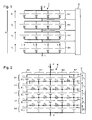
- the figure 1 represents a lithium-ion storage battery 1 known from the state of the art.
- the battery 1 is composed of four stages Et1, Et2, Et3 and Et4 connected in series. Each stage has four similar accumulators connected in parallel. The terminals of the accumulators of the same stage are connected together via electrical connections of large section. Each stage is also connected to the adjacent stages by means of electrical connections of large section in order to pass strong currents corresponding to the sum of the currents of the accumulators of a stage.
- One or more loads are intended to be connected to the terminals N and P of the battery 1.
- the voltage across the four stages is denoted respectively U1, U2, U3 and U4.
- the total voltage U between the terminals N and P of the battery 1 is the sum of the voltages U1, U2, U3 and U4.
- the current flowing through each fourth stage accumulator Et4 is denoted respectively I1, I2, I3 and I4.
- the current I generated on the terminal P of the battery 1 is the sum of currents I1, I2, I3 and I4.
- each accumulator In order to protect the battery 1 from the consequences of a short circuit in an accumulator, each accumulator has a fuse connected to it in series. When an accumulator forms a short circuit, the current flowing therethrough increases substantially and melts its series fuse in order to protect the rest of the battery 1. In the absence of a fuse, the dissipation of energy in the battery in short -circuit induce its heating and that of other accumulators discharging. Such dissipation could be the cause of a fire. Lithium-ion technologies based on cobalt oxide and iron phosphate are particularly at risk when a stage includes a large number of batteries in parallel to store a large amount of energy. The use of fuses is therefore particularly appropriate for these technologies.
- a charged accumulator results in a growth of the voltage at its terminals.
- a charged accumulator is considered when it has reached a nominal voltage level defined by its electrochemical process. If charging is interrupted before this voltage is reached, the battery is not fully charged.
- a fault on an accumulator usually results either by shorting the accumulator, or by an open circuit, or by a large leakage current in the accumulator. It is important to know the impact of battery failure on the battery. Open or short-circuiting may cause an overall failure of the entire battery.
- the battery behaves like a resistor which causes a discharge of the accumulators of the considered stage to zero.
- the risks of starting fire are low because the energy is dissipated relatively slowly.
- the discharge of the accumulators of the stage up to a zero voltage deteriorates them, which implies their replacement in addition to the initially defective accumulator.
- the other three accumulators of the stage will initially discharge into this accumulator, because of the strong section of the electrical connections between them.
- the fuse placed in series with the battery in short circuit will interrupt the parasitic discharge of the other three accumulators.
- Such a battery has a number of disadvantages.
- the fuses are sized to be traversed by large currents, and thus induce significant additional cost.
- the internal resistance of the fuses increases the Joule losses inside the battery, which significantly reduces its performance in power.
- the document US6051955 discloses a storage battery comprising two branches connected in parallel. Each branch includes 3 accumulators connected in series. These accumulators are charged and discharged via two output terminals. Protection transistors are interposed between one of the output terminals and each battery branch. A monitoring circuit detects an excessive charge or discharge of the elements. If this is the case, the monitoring circuit opens the protection transistors between the output terminal and the accumulator branches.
- Each accumulator of one branch is connected in parallel with an accumulator of the other branch.
- Two fuses connected in series thus connect two respective accumulators.
- the monitoring circuit is connected to each node between two fuses in series.
- This accumulator battery further comprises fuses connected in series between a branch and a protective transistor.
- each branch has four accumulators connected in series.
- the accumulators of the two branches are of different types: the first branch comprises high-power accumulators, while the second branch comprises accumulators of high capacity.
- Each high capacity accumulator is connected in parallel with a high power accumulator via a resistor.
- This battery has in practice disadvantages. High power batteries do not significantly improve battery capacity. Moreover, the battery is in practice not protected from certain malfunctions. Thus, a short circuit in an accumulator can induce an overcurrent in the accumulator to which it is connected in parallel via a resistor. Since the accumulators of the two branches are of different types, no compensation can be envisaged in the event of a battery failure.
- the invention aims to solve one or more of these disadvantages without altering the level of security provided by the battery.
- the invention thus relates to an accumulator battery, comprising at least first and second branches each having at least first and second accumulators connected in series, the battery further comprising a circuit breaker through which the first accumulators are connected. in parallel and through which the second accumulators are connected in parallel.
- the breaking threshold of the circuit breaker is sized to conduct the current when one of said accumulators forms an open circuit.
- the battery comprises a third branch having first and second accumulators connected in series, the battery further comprising another circuit breaker through which the first accumulators are connected in parallel and through which the second accumulators are connected in parallel.
- said first accumulators form a first stage of the battery and said second accumulators form a second stage of the battery, the battery further comprising a circuit for balancing the charge of the accumulators connected to the terminals of each stage.
- each junction between the accumulators in parallel is connected to the balancing circuit.
- the accumulators of the first and third branches are non-adjacent, and the balancing circuit is connected to the terminals of the accumulators of the first and third branches.
- the section of the junction between the accumulators in parallel is less than the section of the junction between the accumulators in series.
- the circuit breaker comprises a fusible electrical connection.
- the breaking threshold of the circuit breaker is sized to open when one of said accumulators is short-circuited.
- said accumulators are of a type for which the application of a voltage at their upper terminals of 15% to their nominal voltage does not induce their destruction.
- the accumulators are of the lithium-ion type.
- said branches are devoid of protection circuit breakers arranged in series with said accumulators.
- the internal resistance of said accumulators is lower than the internal resistance of said circuit breaker.
- the invention proposes a battery comprising at least first and second branches each having at least first and second accumulators connected in series, the battery further comprising a circuit breaker through which the first accumulators are connected in parallel and by the intermediate of which the second accumulators are connected in parallel.
- the breaking threshold of the circuit breaker is sized to conduct current when one of said accumulators forms an open circuit.
- the circuit breaker effectively protects the batteries of the battery against overcurrent during a malfunction, at a reduced cost and with less dissipation by Joule effect in normal operation.
- the circuit breaker makes it possible to continue using the battery by allowing all the functional accumulators to compensate for the failure of a battery in a circuit breaker.
- the figure 2 represents a battery 4 according to a first embodiment of the invention.
- the battery 4 has a positive terminal P and a negative terminal N. One or more charges can be connected between the terminals P and N.
- the battery 4 comprises several branches Br1 to Br5. In the example illustrated, the battery 4 comprises five branches. An index j will then correspond to the branch Br j .
- Each branch Br j comprises several accumulators E i, j connected in series, of lithium-ion type based on iron phosphate.
- Branch Br 1 includes accumulators E 1.1 , E 2.1 , E 3.1 , E 4.1 and E 5.1 .
- each branch Br j comprises five accumulators E i, j .
- An index i will subsequently correspond to a stage Et i including five accumulators respectively belonging to each of the branches.
- a breaker is generally designated by a circuit breaker to prevent the passage of electric current and making this interruption in case of overload to protect the components to which it is connected.
- the accumulators E 1, j of the first stage Et 1 are connected in parallel.
- the accumulators E 1, j are connected by their positive terminal to the terminal P of the battery 4.
- the connection of these positive terminals to the terminal P is advantageously achieved by connectors of large section because this connection has a function of collector currents parallel of the different branches.
- the negative terminals of the accumulators E 1, j of the first stage Et 1 are connected together via circuit breakers.
- the circuit breaker D 2.1 connects the negative terminal of the battery E 1.1 to the negative terminal of the battery E 1.2 .
- the accumulators E 2, j of the second stage Et 2 are also connected in parallel.
- the accumulators E 3, j of the third stage Et 3 on the one hand, and the accumulators E 4, j of the fourth stage Et 4 on the other hand, are also connected in parallel.
- the positive terminals of the accumulators of the same stage are connected together via circuit breakers and their negative terminals are also connected together via circuit breakers.
- each circuit breaker is used for a parallel connection for two adjacent stages (two stages sharing connection nodes).
- the circuit breaker D 2.1 is used to connect in parallel the accumulators E 1.1 and E 1.2 but also to connect in parallel the accumulators E 2.1 and E 2.2 .
- the accumulators E 5, j of the fifth stage Et 5 are connected in parallel.
- the positive terminals of the accumulators E 5, j of the fifth stage Et 5 are connected together via circuit breakers.
- the circuit breaker D 5.1 connects the positive terminal of the battery E 5.1 to the positive terminal of the battery E 5.2 .
- the accumulators E 5, j are connected by their negative terminal to the N terminal of the battery 4. The connection of these negative terminals to the N terminal is advantageously carried out by connectors of large section because this connection has a function of introducing the parallel currents in the different branches.
- a charging and balancing circuit 5 is connected to the terminals of each of the stages. Those skilled in the art will determine a suitable circuit 5 for balancing the voltages of the accumulators of each stage and manage the charge of each of the accumulators.
- the current passing through an accumulator E i, j is denoted I i, j .
- the current flowing through a circuit breaker D i, j is denoted It i, j .
- the voltage across a stage i is denoted U i .
- the current exchanged by the positive terminals of a stage i with the charging and balancing circuit 5 is denoted by leq (i) .
- a circuit breaker is defined as being an electrical protection device whose function is to interrupt or limit very strongly (for example by a factor of 100) the electric current passing through it in the event of an overload on an electric circuit.
- the sizing of the circuit breakers of the illustrated example will be detailed later.
- the figure 3 represents a theoretical example of battery 4 in normal operation, in the presence of a load 3 connected between its terminals P and N.
- the load 3 is likened to a resistance of 0.2Ohms.
- Each accumulator is assimilated to a voltage source of 3.3V in series with a resistance of 0.01Ohms (representative of its internal resistance).
- Circuit breakers are considered to be 0.0150hms resistors with a threshold of cutoff is at 6A.
- the connection between the series accumulators of the same branch is suitably dimensioned to withstand the rated current of the branch.
- the accumulators are in this example at their maximum load and all have the same load. Thus, no current flows through the circuit breakers. Thus, in normal operation, the circuit breakers do not induce losses by Joule effect since the currents passing through them are zero. The losses by Joule effect inside the battery 4 are here only induced by the internal resistance of the accumulators. The power efficiency of the battery is thus optimized.
- Each branch is traversed by a current of 15.7A, inducing a current of 78.5A (rounded values) through the load 3.
- the circuit breakers are arranged in parallel connections between the accumulators. In normal operation, these connections must only be traversed by reduced currents during charging or balancing of the various accumulators (in particular at the end of charge of the battery 4). The currents flowing through the circuit breakers during normal operation always remain below their cutoff threshold. Therefore, the size of the circuit breakers used may be significantly smaller than that which would be necessary for circuit breakers arranged in series. It can also be noted that the number of circuit breakers used is less than that which would be necessary for series circuit breakers. The cost of the battery 4 is thus significantly reduced.
- the circuit-breakers have a cutoff threshold lower than the maximum charge or discharge current tolerated for a battery.
- the cut-off threshold is 6A and is significantly lower than the current of 15.7A passing through each of the accumulators at the figure 3 .
- the figure 4 illustrates theoretical current values, assuming that the accumulator E 3.3 forms a short-circuit and in the absence of a break by the circuit-breakers. Assuming that the maximum charging or discharging current of an accumulator is 30A, it is found that all the accumulators of the third stage would be susceptible to deterioration. It can be seen that the parallel connections between the accumulators are subjected to more or less significant currents.
- the circuit-breakers D 2.2 , D 2.3 , D 3.2 , D 3.3 , D 4.2 , D 4.3 D 5.2 , and D 5.3 would be traversed by currents greater than their threshold. cut.
- the circuit breakers D 2.2 , D 2.3 , D 3.2 , D 3.3 , D 4.2 , D 4.3 D 5.2 , and D 5.3 are open because of the overcurrents induced by the battery E 3.3 . Overcurrents are thus limited in time, which eliminates any risk of fire starting by heating an accumulator.
- Overcurrents are thus limited in time, which eliminates any risk of fire starting by heating an accumulator.
- This negative current makes it possible to charge the accumulators E 1.3 , E 2.3 , E 4.3 and E 5.3 up to a voltage of 3.88V to compensate for the failure of the battery E 3.3 in short -circuit.
- branches Br 1 , Br 2 , Br 3 and Br 4 are traversed by a current of 19.4A, lower than the rated current of 30A accumulators.
- the accumulators of the various branches are thus well protected against overcurrents induced by a short circuit in one of the accumulators.
- the transverse currents It i, j are zero.
- the current passing through the load 3 is 77.6A, which is close to the normal running current of the battery 4.
- the figure 6 represents discharge profiles of the battery 4 respectively in normal operation (solid line) and in the presence of a short-circuited battery (broken line). It is found that the voltage between terminals N and P of the battery 4 at full load is maintained at the same level.
- the discharge limit threshold S of the battery 4 is reached earlier at a time T2. In normal operation, this discharge threshold is only reached at a time T1. The performance of the battery 4 is thus reduced in the presence of the failure.
- the circuit 3 can detect the failure of an accumulator by noting a decrease in the discharge duration below a predefined threshold. This failure can be reported to the user of the battery 4 to signal the need for repair.
- the battery 4 still remains functional for several charge / discharge cycles before repair. Since the circuit breakers have prevented deterioration of other accumulators, the repair may consist of changing only the faulty accumulator.
- the figure 7 illustrates the battery 4 during a failure of an accumulator forming an open circuit or circuit breaker, in this case the battery E 3.3 .
- the circuit breakers forming parallel connections allow the other accumulators to compensate for the failure of the accumulator E 3.3 .
- the circuit breakers D 2.1 , D 2.4 , D 5.1 and D 5.4 are traversed by a current of 0.5A.
- the circuit breakers D 3.1 , D 3.4 , D 4.1 and D 4.4 are traversed by a current of 0.9A.
- the circuit breakers D 2.2 , D 2.3 , D 5.2 and D 5.3 are traversed by a current of 1.4A.
- the circuit breakers D 3.2 , D 3.3 , D 4.2 and D 4.3 are crossed by a current of 5.3A. Thus, none of the currents flowing through the circuit breakers exceeds the breaking threshold of these circuit breakers. Thus, all the functional accumulators are discharged, the capacity of the battery 4 thus being reduced to a small extent. The battery 4 therefore remains functional for a number of charge / discharge cycles.
- the accumulators E 1, j of the first stage Et 1 are traversed respectively by currents of 16.6A, 15.7A, 13, 6A, 15.7A and 16.6A, lower than the nominal limit of each of these accumulators.
- the circuit 5 will be able to identify the failure of the accumulator E 3.3 , in particular because of the faster discharge of the stage Et 3 . This failure can be reported to the user of the battery 4 to signal the need for repair.
- the sizing of the circuit breakers is advantageously carried out so that a short-circuited accumulator induces a cut-off by at least one circuit breaker, and so that an open-circuit accumulator leads to currents in the various circuit-breakers that do not induce cut-offs. .
- the circuit 5 is connected to the branches Br 1 to Br 4 via the nodes of the branch Br 5 .
- the branches beyond are no longer connected to the circuit 5 and can no longer be balanced.
- branches Br 1 and Br 2 are no longer balanced by circuit 5.
- the figure 8 illustrates an embodiment of a battery 4 solving this disadvantage.
- the principle of this embodiment is to connect together the nodes of the same stage of opposite branches.
- the nodes of branches Br 1 and Br 5 are connected together respectively via circuit breakers D 2 to D 5 .
- the circuit 5 can thus load and balance all the non-faulty branches even in the presence of a faulty branch. It is also conceivable to connect two non-adjacent accumulators of the same stage to the balancing circuit 5.
- the figure 9 represents another embodiment in which the terminals of the accumulators of the same stage are all connected to a same terminal of the circuit 5. Such a connection facilitates the load balancing performed by the circuit 5. In addition, such a connection is particularly advantageous when each stage is formed of several accumulators distributed radially to form a battery of substantially cylindrical shape as shown in figure 10 .
- the dotted lines correspond to the electrical connections in series between the different stages of the battery 4.
- the figure 11 is a schematic representation of another embodiment of a storage battery 4 according to the invention.
- Br 1 and Br 5 branch nodes are connected together respectively via circuit breakers D 2 to D 5 in order to load and balance all non-faulty branches, even in the presence of a branch. faulty.
- the circuit 5 is connected to the terminals of each accumulator stage, via the connections L1 to L6.
- the circuit 5 has a direct connection (connection not passing through a connection node between two accumulators) with each of the branches Br1 to Br5, in this case at the nodes N2 to N5.
- the nodes N2 to N5 connected directly to the circuit 5 serially connect two accumulators of the same branch.
- each connection of the circuit 5 to a node N2 to N5 thus makes it possible to determine both the faulty branch and to charge a stage of the battery 4.
- the resistance of the parallel connections of the accumulators is advantageously greater than the internal resistance of the accumulators. This limits the amplitude of the currents in the accumulators before the circuit breakers induce a break. It also limits the incidence of battery failure on distant branches.
- the value of the resistance of the circuit breakers is limited in order to avoid increasing to a greater extent the charging time of the branches remote from the circuit 5.
- circuit breakers are in this case fuses.
- the conducting section of a fuse blows in the presence of a current greater than its nominal threshold.
- Other types of circuit breakers can of course be used. It will be possible to use circuit breakers of resettable type. Circuit breakers of type CTP (with positive temperature coefficient, whose resistance increases strongly and brutally with the temperature) can also be used. Increasing the resistance of such a circuit breaker limits the current flowing through it to very low values, leading to dissipation without fusion of the energy produced by Joule effect. If the fault causing the current in the circuit breaker disappears, the circuit breaker gradually regains its initial conduction level. Circuit breakers of the CTP type are in particular commercially available.
Landscapes
- Chemical & Material Sciences (AREA)
- Chemical Kinetics & Catalysis (AREA)
- Electrochemistry (AREA)
- General Chemical & Material Sciences (AREA)
- Engineering & Computer Science (AREA)
- Manufacturing & Machinery (AREA)
- Materials Engineering (AREA)
- Power Engineering (AREA)
- Charge And Discharge Circuits For Batteries Or The Like (AREA)
- Connection Of Batteries Or Terminals (AREA)
- Secondary Cells (AREA)
- Battery Mounting, Suspending (AREA)
Description
L'invention concerne les batteries d'accumulateurs électrochimiques. Celles-ci peuvent par exemple être utilisées dans le domaine des transports électriques et hybrides ou les systèmes embarqués.The invention relates to electrochemical storage batteries. These can for example be used in the field of electric and hybrid transport or embedded systems.
Un accumulateur électrochimique a habituellement une tension nominale de l'ordre de grandeur suivant :
- 1.2 V pour des batteries de type NiMH,
- 3.3 V pour une technologie lithium-ion phosphate de Fer, LiFePO4,
- 4.2 V pour une technologie de type lithium-ion à base d'oxyde de cobalt.
- 1.2 V for NiMH batteries,
- 3.3 V for a Lithium Iron Phosphate LiFePO4 technology,
- 4.2 V for lithium-ion technology based on cobalt oxide.
Ces tensions nominales sont trop faibles par rapport aux exigences de la plupart des systèmes à alimenter. Pour obtenir le niveau de tension adéquat, on place en série plusieurs accumulateurs. Pour obtenir de fortes puissances et capacités, on place plusieurs accumulateurs en parallèle. Le nombre d'étages (nombre d'accumulateurs en série) et le nombre d'accumulateurs en parallèle dans chaque étage varient en fonction de la tension, du courant et de la capacité souhaités pour la batterie. L'association de plusieurs accumulateurs est appelée une batterie d'accumulateurs.These nominal voltages are too low compared to the requirements of most systems to power. To obtain the correct voltage level, several accumulators are placed in series. To obtain high powers and capacities, several accumulators are placed in parallel. The number of stages (number of accumulators in series) and the number of accumulators in parallel in each stage vary according to the voltage, current and capacity desired for the battery. The combination of several accumulators is called a storage battery.
Lors de la conception d'une batterie d'accumulateurs, on cherche à fournir un certain niveau de puissance sous une tension de fonctionnement définie. Pour maximiser la puissance, on maximise le courant délivré en réduisant autant que possible la résistance interne parasite de la batterie.When designing a storage battery, it is sought to provide a certain level of power under a defined operating voltage. To maximize the power, the delivered current is maximized by reducing as much as possible the parasitic internal resistance of the battery.
Les batteries de type lithium-ion sont bien adaptées pour des applications de transport par leur capacité à stocker une énergie importante dans une faible masse. Parmi les technologies de batteries lithium-ion, les batteries à base de phosphate de fer offrent un haut niveau de sécurité intrinsèque par rapport aux batteries lithium-ion à base d'oxyde de cobalt, au détriment d'une énergie massique un peu inférieure. Par ailleurs, les batteries lithium-ion présentent aussi une tension minimale en dessous de laquelle un accumulateur peut subir une dégradation.Lithium-ion type batteries are well suited for transport applications by their ability to store a large amount of energy in a low mass. Among lithium-ion battery technologies, iron phosphate batteries offer a high level of intrinsic safety compared to lithium-ion batteries based on cobalt oxide, to the detriment of a slightly lower specific energy. In addition, lithium-ion batteries also have a minimum voltage below which a battery can be damaged.
La
La tension aux bornes des quatre étages est notée respectivement U1, U2, U3 et U4. Dans ce schéma, la tension totale U entre les bornes N et P de la batterie 1 est la somme des tensions U1, U2, U3 et U4. Le courant traversant chaque accumulateur du quatrième étage Et4 est notée respectivement I1, I2, I3 et I4. Le courant I généré sur la borne P de la batterie 1 est la somme des courants I1, I2, I3 et I4.The voltage across the four stages is denoted respectively U1, U2, U3 and U4. In this diagram, the total voltage U between the terminals N and P of the
Afin de protéger la batterie 1 des conséquences d'un court-circuit dans un accumulateur, chaque accumulateur présente un fusible qui lui est connecté en série. Lorsqu'un accumulateur forme un court-circuit, le courant le traversant augmente sensiblement et fait fondre son fusible série afin de protéger le reste de la batterie 1. En l'absence de fusible, la dissipation d'énergie dans l'accumulateur en court-circuit induirait son échauffement ainsi que celui des autres accumulateurs se déchargeant. Une telle dissipation pourrait être la cause d'un départ de feu. Les technologies lithium-ion à base d'oxyde de Cobalt et à base de phosphate de fer sont particulièrement à risque lorsqu'un étage comprend un grand nombre d'accumulateurs en parallèle pour stocker une énergie importante. L'utilisation de fusibles s'avère donc particulièrement appropriée pour ces technologies.In order to protect the
Les différents accumulateurs d'une batterie lithium-ion n'écrêtent pas naturellement la tension à leurs bornes. Il est nécessaire d'ajouter pour chaque étage un circuit annexe 2 d'équilibrage et de contrôle de charge, pour que les étages Et1 à Et4 puissent être chargés correctement. La mise en série de quatre étages de quatre accumulateurs nécessite d'associer à chaque étage une fonction d'équilibrage et de contrôle de charge. Le circuit 2 gère donc la charge et l'équilibrage de chaque étage de la batterie 1.The different accumulators of a lithium-ion battery do not naturally stop the voltage at their terminals. It is necessary to add for each stage an
La charge d'un accumulateur se traduit par une croissance de la tension à ses bornes. On considère un accumulateur chargé lorsque celui-ci a atteint un niveau de tension nominal défini par son processus électrochimique. Si la charge est interrompue avant que cette tension ne soit atteinte, l'accumulateur n'est pas complètement chargé.The charge of an accumulator results in a growth of the voltage at its terminals. A charged accumulator is considered when it has reached a nominal voltage level defined by its electrochemical process. If charging is interrupted before this voltage is reached, the battery is not fully charged.
Dans toute la durée de vie de la batterie, certains défauts peuvent apparaître sur certains accumulateurs composant la batterie. Un défaut sur un accumulateur se traduit généralement soit par la mise en court-circuit de l'accumulateur, soit par une mise en circuit ouvert, soit par un courant de fuite important dans l'accumulateur. Il est important de connaître l'impact de la défaillance d'un accumulateur sur la batterie. Une mise en circuit ouvert ou en court-circuit peut provoquer une défaillance globale de toute la batterie.Throughout the life of the battery, some faults may appear on some accumulators making up the battery. A fault on an accumulator usually results either by shorting the accumulator, or by an open circuit, or by a large leakage current in the accumulator. It is important to know the impact of battery failure on the battery. Open or short-circuiting may cause an overall failure of the entire battery.
Dans le cas de l'apparition d'un courant de fuite important dans un accumulateur d'un étage, la batterie se comporte comme une résistance qui provoque une décharge des accumulateurs de l'étage considéré jusqu'à zéro. Les risques de départ de feu sont faibles car l'énergie est dissipée relativement lentement. En technologie lithium-ion, la décharge des accumulateurs de l'étage jusqu'à une tension nulle les détériore ce qui implique leur remplacement en plus de l'accumulateur initialement défaillant. Lorsqu'un accumulateur forme un court-circuit, les trois autres accumulateurs de l'étage vont initialement se décharger dans cet accumulateur, du fait de la forte section des connexions électriques entre eux. Le fusible placé en série avec l'accumulateur en court-circuit va interrompre la décharge parasite des trois autres accumulateurs.In the case of the appearance of a large leakage current in a one-stage accumulator, the battery behaves like a resistor which causes a discharge of the accumulators of the considered stage to zero. The risks of starting fire are low because the energy is dissipated relatively slowly. In lithium-ion technology, the discharge of the accumulators of the stage up to a zero voltage deteriorates them, which implies their replacement in addition to the initially defective accumulator. When an accumulator forms a short circuit, the other three accumulators of the stage will initially discharge into this accumulator, because of the strong section of the electrical connections between them. The fuse placed in series with the battery in short circuit will interrupt the parasitic discharge of the other three accumulators.
Une telle batterie présente un certain nombre d'inconvénients. Les fusibles sont dimensionnés pour être traversés par des courants importants, et induisent ainsi un surcoût important. De plus, la résistance interne des fusibles augmente les pertes par effet Joule à l'intérieur de la batterie, ce qui réduit notablement ses performances en puissance.Such a battery has a number of disadvantages. The fuses are sized to be traversed by large currents, and thus induce significant additional cost. In addition, the internal resistance of the fuses increases the Joule losses inside the battery, which significantly reduces its performance in power.
Le document
Chaque accumulateur d'une branche est connecté en parallèle à un accumulateur de l'autre branche. Deux fusibles connectés en série connectent ainsi deux accumulateurs respectifs. Le circuit de surveillance est connecté à chaque noeud entre deux fusibles en série.Each accumulator of one branch is connected in parallel with an accumulator of the other branch. Two fuses connected in series thus connect two respective accumulators. The monitoring circuit is connected to each node between two fuses in series.
Cette batterie d'accumulateurs comprend de plus des fusibles connectés en série entre une branche et un transistor de protection.This accumulator battery further comprises fuses connected in series between a branch and a protective transistor.
Une telle batterie présente un certain nombre d'inconvénients :
- d'importantes pertes par effet Joule sont induites par les fusibles en série et les transistors de protection durant le fonctionnement de la batterie ;
- toute défaillance d'un accumulateur induit l'interruption immédiate du fonctionnement de la batterie par le circuit de surveillance ;
- la capacité de la batterie n'est pas optimale : en charge, l'accumulateur le plus chargé interrompt la charge de la batterie alors que les autres accumulateurs n'ont pas encore atteint leur charge optimale. En décharge, l'accumulateur le moins chargé interrompt la décharge alors que les autres accumulateurs n'ont pas atteint leur seuil de décharge.
- large Joule losses are caused by series fuses and protective transistors during battery operation;
- any failure of an accumulator induces the immediate interruption of the operation of the battery by the monitoring circuit;
- the battery capacity is not optimal: charging, the most charged battery interrupts the charging of the battery while other accumulators have not yet reached their optimal charge. In discharge, the least charged battery interrupts the discharge while the other accumulators have not reached their discharge threshold.
Le document
Cette batterie présente en pratique des inconvénients. Les accumulateurs de forte puissance n'améliorent pas notablement la capacité de la batterie. Par ailleurs, la batterie n'est en pratique pas protégée de certains dysfonctionnements. Ainsi, un court-circuit dans un accumulateur peut induire une surintensité dans l'accumulateur auquel il est connecté en parallèle par l'intermédiaire d'une résistance. Les accumulateurs des deux branches étant en outre de types différents, aucune compensation n'est envisageable en cas de défaillance d'un accumulateur.This battery has in practice disadvantages. High power batteries do not significantly improve battery capacity. Moreover, the battery is in practice not protected from certain malfunctions. Thus, a short circuit in an accumulator can induce an overcurrent in the accumulator to which it is connected in parallel via a resistor. Since the accumulators of the two branches are of different types, no compensation can be envisaged in the event of a battery failure.
L'invention vise à résoudre un ou plusieurs de ces inconvénients sans altérer le niveau de sécurité fourni par la batterie. L'invention porte ainsi sur une batterie d'accumulateurs, comprenant au moins des première et deuxième branches présentant chacune au moins des premier et deuxième accumulateurs connectés en série, la batterie comprenant en outre un disjoncteur par l'intermédiaire duquel les premiers accumulateurs sont connectés en parallèle et par l'intermédiaire duquel les deuxièmes accumulateurs sont connectés en parallèle. Le seuil de coupure du disjoncteur est dimensionné pour conduire le courant lorsque l'un desdits accumulateurs forme un circuit ouvert.The invention aims to solve one or more of these disadvantages without altering the level of security provided by the battery. The invention thus relates to an accumulator battery, comprising at least first and second branches each having at least first and second accumulators connected in series, the battery further comprising a circuit breaker through which the first accumulators are connected. in parallel and through which the second accumulators are connected in parallel. The breaking threshold of the circuit breaker is sized to conduct the current when one of said accumulators forms an open circuit.
Selon une variante, la batterie comprend une troisième branche présentant des premier et deuxième accumulateurs connectés en série, la batterie comprenant en outre un autre disjoncteur par l'intermédiaire duquel les premiers accumulateurs sont connectés en parallèle et par l'intermédiaire duquel les deuxièmes accumulateurs sont connectés en parallèle.According to a variant, the battery comprises a third branch having first and second accumulators connected in series, the battery further comprising another circuit breaker through which the first accumulators are connected in parallel and through which the second accumulators are connected in parallel.
Selon une autre variante, lesdits premiers accumulateurs forment un premier étage de la batterie et lesdits deuxièmes accumulateurs forment un second étage de la batterie, la batterie comprenant en outre un circuit d'équilibrage de la charge des accumulateurs connecté aux bornes de chaque étage.According to another variant, said first accumulators form a first stage of the battery and said second accumulators form a second stage of the battery, the battery further comprising a circuit for balancing the charge of the accumulators connected to the terminals of each stage.
Selon encore une variante, chaque jonction entre les accumulateurs en parallèle est raccordée au circuit d'équilibrage.According to another variant, each junction between the accumulators in parallel is connected to the balancing circuit.
Selon encore une autre variante, les accumulateurs des première et troisième branches sont non adjacents, et le circuit d'équilibrage est connecté aux bornes des accumulateurs des première et troisième branches.According to yet another variant, the accumulators of the first and third branches are non-adjacent, and the balancing circuit is connected to the terminals of the accumulators of the first and third branches.
Selon une variante, la section de la jonction entre les accumulateurs en parallèle est inférieure à la section de la jonction entre les accumulateurs en série.Alternatively, the section of the junction between the accumulators in parallel is less than the section of the junction between the accumulators in series.
Selon encore une variante, le disjoncteur comprend une connexion électrique fusible.According to another variant, the circuit breaker comprises a fusible electrical connection.
Selon une autre variante, le seuil de coupure du disjoncteur est dimensionné pour s'ouvrir lorsque l'un desdits accumulateurs est en court-circuit.According to another variant, the breaking threshold of the circuit breaker is sized to open when one of said accumulators is short-circuited.
Selon une variante, lesdits accumulateurs sont d'un type pour lequel l'application d'une tension à leurs bornes supérieure de 15% à leur tension nominale n'induit pas leur destruction.According to a variant, said accumulators are of a type for which the application of a voltage at their upper terminals of 15% to their nominal voltage does not induce their destruction.
Selon encore une variante, les accumulateurs sont de type lithium-ion.According to another variant, the accumulators are of the lithium-ion type.
Selon une autre variante, lesdites branches sont dépourvues de disjoncteurs de protection disposés en série avec lesdits accumulateurs.According to another variant, said branches are devoid of protection circuit breakers arranged in series with said accumulators.
Selon une autre variante, la résistance interne desdits accumulateurs est inférieure à la résistance interne dudit disjoncteur.According to another variant, the internal resistance of said accumulators is lower than the internal resistance of said circuit breaker.
D'autres caractéristiques et avantages de l'invention ressortiront clairement de la description qui en est faite ci-après, à titre indicatif et nullement limitatif, en référence aux dessins annexés, dans lesquels :
- la
figure 1 est une représentation schématique d'une batterie de l'état de la technique ; - la
figure 2 est une représentation schématique d'un mode de réalisation d'une batterie selon l'invention ; - la
figure 3 représente schématiquement des courants traversant des accumulateurs de la batterie en fonctionnement normal ; - la
figure 4 représente schématiquement les courants dans la batterie en présence d'un court-circuit lorsque les disjoncteurs sont désactivés ; - la
figure 5 est une représentation schématique des courants traversant les accumulateurs de la batterie postérieurement au court-circuit ; - la
figure 6 est un diagramme représentant des profils de décharge de la batterie ; - la
figure 7 est une représentation schématique des courants en présence d'un accumulateur en circuit ouvert ; - les
figures 8 et le 9 sont des représentations schématiques d'autres modes de réalisation d'une batterie selon l'invention ; - la
figure 10 est une vue en perspective éclatée d'un exemple de disposition d'accumulateurs dans un autre mode de réalisation d'une batterie selon l'invention ; - la
figure 11 est une représentation schématique d'un autre mode de réalisation d'une batterie selon l'invention.
- the
figure 1 is a schematic representation of a battery of the state of the art; - the
figure 2 is a schematic representation of an embodiment of a battery according to the invention; - the
figure 3 schematically represents currents passing through accumulators of the battery in normal operation; - the
figure 4 schematically represents the currents in the battery in the presence of a short circuit when the circuit breakers are deactivated; - the
figure 5 is a schematic representation of the currents flowing through the accumulators of the battery after the short circuit; - the
figure 6 is a diagram showing battery discharge profiles; - the
figure 7 is a schematic representation of the currents in the presence of an open circuit accumulator; - the
figures 8 and 9 are diagrammatic representations of other embodiments of a battery according to the invention; - the
figure 10 is an exploded perspective view of an exemplary battery arrangement in another embodiment of a battery according to the invention; - the
figure 11 is a schematic representation of another embodiment of a battery according to the invention.
L'invention propose une batterie comprenant au moins des première et deuxième branches présentant chacune au moins des premier et deuxième accumulateurs connectés en série, la batterie comprenant en outre un disjoncteur par l'intermédiaire duquel les premiers accumulateurs sont connectés en parallèle et par l'intermédiaire duquel les deuxièmes accumulateurs sont connectés en parallèle. Le seuil de coupure du disjoncteur est dimensionné pour conduire du courant lorsque l'un desdits accumulateurs forme un circuit ouvert.The invention proposes a battery comprising at least first and second branches each having at least first and second accumulators connected in series, the battery further comprising a circuit breaker through which the first accumulators are connected in parallel and by the intermediate of which the second accumulators are connected in parallel. The breaking threshold of the circuit breaker is sized to conduct current when one of said accumulators forms an open circuit.
Le disjoncteur permet de protéger efficacement les accumulateurs de la batterie contre des surintensités lors d'un dysfonctionnement, à un coût réduit et avec une moindre dissipation par effet Joule en fonctionnement normal. De plus, le disjoncteur permet de poursuivre l'utilisation de la batterie en permettant à l'ensemble des accumulateurs fonctionnels de compenser la défaillance d'un accumulateur en coupe-circuit.The circuit breaker effectively protects the batteries of the battery against overcurrent during a malfunction, at a reduced cost and with less dissipation by Joule effect in normal operation. In addition, the circuit breaker makes it possible to continue using the battery by allowing all the functional accumulators to compensate for the failure of a battery in a circuit breaker.
La
Les accumulateurs d'un même étage sont connectés en parallèle par l'intermédiaire de disjoncteurs. On désigne généralement par disjoncteur un interrupteur permettant d'empêcher le passage du courant électrique et effectuant cette interruption en cas de surcharge afin de protéger les composants auxquels il est connecté.Accumulators of the same stage are connected in parallel through circuit breakers. A breaker is generally designated by a circuit breaker to prevent the passage of electric current and making this interruption in case of overload to protect the components to which it is connected.
Les accumulateurs E1,j du premier étage Et1 sont connectés en parallèle. Les accumulateurs E1,j sont connectés par leur borne positive à la borne P de la batterie 4. La connexion de ces bornes positives à la borne P est avantageusement réalisée par des connecteurs de forte section car cette connexion a une fonction de collecteur des courants parallèles des différentes branches. Les bornes négatives des accumulateurs E1,j du premier étage Et1 sont connectées ensemble par l'intermédiaire de disjoncteurs. Ainsi, le disjoncteur D2,1 connecte la borne négative de l'accumulateur E1,1 à la borne négative de l'accumulateur E1,2.The accumulators E 1, j of the first stage Et 1 are connected in parallel. The accumulators E 1, j are connected by their positive terminal to the terminal P of the
Les accumulateurs E2,j du deuxième étage Et2 sont également connectés en parallèle. Les accumulateurs E3,j du troisième étage Et3 d'une part, et les accumulateurs E4,j du quatrième étage Et4 d'autre part, sont également connectés en parallèle. Pour chacun de ces étages intermédiaires, les bornes positives des accumulateurs d'un même étage sont connectées ensemble par l'intermédiaire de disjoncteurs et leurs bornes négatives sont également connectées ensemble par l'intermédiaire de disjoncteurs.The accumulators E 2, j of the second stage Et 2 are also connected in parallel. The accumulators E 3, j of the third stage Et 3 on the one hand, and the accumulators E 4, j of the fourth stage Et 4 on the other hand, are also connected in parallel. For each of these intermediate stages, the positive terminals of the accumulators of the same stage are connected together via circuit breakers and their negative terminals are also connected together via circuit breakers.
Comme illustré, chaque disjoncteur est utilisé pour une connexion en parallèle pour deux étages adjacents (deux étages partageant des noeuds de connexion). Ainsi, le disjoncteur D2,1 est utilisé pour connecter en parallèle les accumulateurs E1,1 et E1,2 mais également pour connecter en parallèle les accumulateurs E2,1 et E2,2.As illustrated, each circuit breaker is used for a parallel connection for two adjacent stages (two stages sharing connection nodes). Thus, the circuit breaker D 2.1 is used to connect in parallel the accumulators E 1.1 and E 1.2 but also to connect in parallel the accumulators E 2.1 and E 2.2 .
Les accumulateurs E5,j du cinquième étage Et5 sont connectés en parallèle. Les bornes positives des accumulateurs E5,j du cinquième étage Et5 sont connectées ensemble par l'intermédiaire de disjoncteurs. Ainsi, le disjoncteur D5,1 connecte la borne positive de l'accumulateur E5,1 à la borne positive de l'accumulateur E5,2. Les accumulateurs E5,j sont connectés par leur borne négative à la borne N de la batterie 4. La connexion de ces bornes négatives à la borne N est avantageusement réalisée par des connecteurs de forte section car cette connexion a une fonction d'introduction des courants parallèles dans les différentes branches.The accumulators E 5, j of the fifth stage Et 5 are connected in parallel. The positive terminals of the accumulators E 5, j of the fifth stage Et 5 are connected together via circuit breakers. Thus, the circuit breaker D 5.1 connects the positive terminal of the battery E 5.1 to the positive terminal of the battery E 5.2 . The accumulators E 5, j are connected by their negative terminal to the N terminal of the
Un circuit de charge et d'équilibrage 5 est connecté aux bornes de chacun des étages. L'homme du métier déterminera un circuit 5 adéquat pour réaliser l'équilibrage des tensions des accumulateurs de chaque étage et gérer la charge de chacun des accumulateurs.A charging and balancing
Le courant traversant un accumulateur Ei,j est noté Ii,j. Le courant traversant un disjoncteur Di,j est noté Iti,j. La tension aux bornes d'un étage i est notée Ui. Le courant échangé par les bornes positives d'un étage i avec le circuit de charge et d'équilibrage 5 est noté leq(i).The current passing through an accumulator E i, j is denoted I i, j . The current flowing through a circuit breaker D i, j is denoted It i, j . The voltage across a stage i is denoted U i . The current exchanged by the positive terminals of a stage i with the charging and balancing
Un disjoncteur est défini comme étant un dispositif de protection électrique dont la fonction est d'interrompre ou de limiter très fortement (par exemple par un facteur 100) le courant électrique le traversant en cas de surcharge sur un circuit électrique. Le dimensionnement des disjoncteurs de l'exemple illustré sera détaillé ultérieurement.A circuit breaker is defined as being an electrical protection device whose function is to interrupt or limit very strongly (for example by a factor of 100) the electric current passing through it in the event of an overload on an electric circuit. The sizing of the circuit breakers of the illustrated example will be detailed later.
La
Les accumulateurs sont dans cet exemple à leur charge maximale et présentent tous une charge identique. Ainsi, aucun courant ne traverse les disjoncteurs. On constate ainsi qu'en fonctionnement normal, les disjoncteurs n'induisent pas de pertes par effet Joule puisque les courants les traversant sont nuls. Les pertes par effet Joule à l'intérieur de la batterie 4 sont ici uniquement induites par la résistance interne des accumulateurs. L'efficacité en puissance de la batterie est ainsi optimisée. Chaque branche est traversée par un courant de 15,7A, induisant un courant de 78,5A (valeurs arrondies) à travers la charge 3.The accumulators are in this example at their maximum load and all have the same load. Thus, no current flows through the circuit breakers. Thus, in normal operation, the circuit breakers do not induce losses by Joule effect since the currents passing through them are zero. The losses by Joule effect inside the
Les disjoncteurs sont disposés dans les connexions en parallèle entre les accumulateurs. En fonctionnement normal, ces connexions ne doivent être parcourues que par des courants réduits lors de la charge ou de l'équilibrage des différents accumulateurs (en particulier en fin de charge de la batterie 4). Les courants traversant les disjoncteurs en fonctionnement normal restent toujours inférieurs à leur seuil de coupure. Par conséquent, le dimensionnement des disjoncteurs utilisés peut être nettement inférieur à celui qui serait nécessaire pour des disjoncteurs disposés en série. On peut également constater que le nombre de disjoncteurs utilisés est inférieur à celui qui serait nécessaire pour des disjoncteurs série. Le coût de la batterie 4 est ainsi notablement réduit.The circuit breakers are arranged in parallel connections between the accumulators. In normal operation, these connections must only be traversed by reduced currents during charging or balancing of the various accumulators (in particular at the end of charge of the battery 4). The currents flowing through the circuit breakers during normal operation always remain below their cutoff threshold. Therefore, the size of the circuit breakers used may be significantly smaller than that which would be necessary for circuit breakers arranged in series. It can also be noted that the number of circuit breakers used is less than that which would be necessary for series circuit breakers. The cost of the
Pour assurer une protection optimale des accumulateurs, les disjoncteurs ont un seuil de coupure inférieur au courant de charge ou de décharge maximal toléré pour un accumulateur. Dans cet exemple, le seuil de coupure est de 6A et est nettement inférieur au courant de 15,7A traversant chacun des accumulateurs à la
La
Ainsi, comme illustré à la
La
La
Le circuit 5 pourra identifier la défaillance de l'accumulateur E3,3, notamment du fait de la décharge plus rapide de l'étage Et3. Cette défaillance peut être signalée à l'utilisateur de la batterie 4 pour lui signaler la nécessité d'une réparation.The
Le dimensionnement des disjoncteurs est avantageusement réalisé de sorte qu'un accumulateur en court-circuit induit une coupure par au moins un disjoncteur, et de sorte qu'un accumulateur en circuit ouvert conduit à des courants dans les différents disjoncteurs n'induisant pas de coupure.The sizing of the circuit breakers is advantageously carried out so that a short-circuited accumulator induces a cut-off by at least one circuit breaker, and so that an open-circuit accumulator leads to currents in the various circuit-breakers that do not induce cut-offs. .
Dans l'exemple illustré aux
La
La
La
La résistance des connexions en parallèle des accumulateurs (par exemple la résistance interne des disjoncteurs) est avantageusement supérieure à la résistance interne des accumulateurs. On limite ainsi l'amplitude des courants dans les accumulateurs avant que les disjoncteurs induisent une coupure. On limite également l'incidence de la défaillance d'un accumulateur sur des branches distantes. Lorsque le circuit 5 est connecté aux noeuds d'une seule branche, on limite la valeur de la résistance des disjoncteurs afin d'éviter d'accroître dans une trop grande mesure le temps de charge des branches distantes du circuit 5.The resistance of the parallel connections of the accumulators (for example the internal resistance of the circuit breakers) is advantageously greater than the internal resistance of the accumulators. This limits the amplitude of the currents in the accumulators before the circuit breakers induce a break. It also limits the incidence of battery failure on distant branches. When the
Les disjoncteurs illustrés sont en l'occurrence des fusibles. La section conductrice d'un fusible fond en présence d'un courant supérieur à son seuil nominal. D'autres types de disjoncteurs peuvent bien entendu être utilisés. On pourra notamment utiliser des disjoncteurs de type réarmable. Des disjoncteurs de type CTP (à coefficient de température positif, dont la résistance croît fortement et brutalement avec la température) pourront également être utilisés. L'augmentation de la résistance d'un tel disjoncteur permet de limiter le courant le traversant à des valeurs très faibles, conduisant à une dissipation sans fusion de l'énergie produite par effet Joule. Si le défaut à l'origine du courant dans le disjoncteur disparaît, le disjoncteur retrouve progressivement son niveau de conduction initial. Des disjoncteurs de type CTP sont notamment disponibles dans le commerce.The illustrated circuit breakers are in this case fuses. The conducting section of a fuse blows in the presence of a current greater than its nominal threshold. Other types of circuit breakers can of course be used. It will be possible to use circuit breakers of resettable type. Circuit breakers of type CTP (with positive temperature coefficient, whose resistance increases strongly and brutally with the temperature) can also be used. Increasing the resistance of such a circuit breaker limits the current flowing through it to very low values, leading to dissipation without fusion of the energy produced by Joule effect. If the fault causing the current in the circuit breaker disappears, the circuit breaker gradually regains its initial conduction level. Circuit breakers of the CTP type are in particular commercially available.
Claims (13)
- A storage battery (4) characterized in that the storage battery comprises at least first and second branches (Br1, Br2) each presenting at least first (E1, 1, E1,2) and second (E2,1, E2,2) storage cells connected in series, the battery also comprising a switch (D2,1) via which the first storage cells are connected in parallel and via which the second storage cells are connected in parallel, the cutoff threshold of the switch being dimensioned to conduct current when one of said storage cells forms an open circuit.
- The battery according to claim 1, comprising a third branch (Br3) presenting first (E1,3) and second (E2,3) storage cells connected in series, the battery (4) also comprising another switch (D2,2) via which the first storage cells are connected in parallel and via which the second storage cells are connected in parallel.
- The battery according to claim 1 or 2, in which said first storage cells form a first stage of the battery and in which said second storage cells form a second stage of the battery, the battery further comprising a balancing circuit (5) for balancing the charge of the storage cells, connected to the terminals of each stage.
- The battery according to claim 3, in which each junction between the storage cells in parallel is connected to the balancing circuit (5).
- The battery according to claims 2 and 3, in which the storage cells of the first and third branches (Br1, Br3) are nonadjacent, and in which the balancing circuit (5) is connected to the terminals of the storage cells of the first and third branches.
- The battery according to claim 3, in which the balancing circuit (5) is connected to each of the branches via a node of each branch connecting two storage cells of the branch in series.
- The battery according to any one of the previous claims, in which the cross section of a junction between storage cells in parallel is smaller than a cross section of a junction between storage cells in series.
- The battery according to any one of the previous claims, in which the switch comprises a fusible electrical connection.
- The battery according to any one of the previous claims, in which the cutoff threshold of the switch is dimensioned to open when one of said storage cells is short-circuited.
- The battery according to any one of the previous claims, in which said storage cells are of a type to withstand the application of voltage above 15% of their nominal voltage at their terminals.
- The battery according to any one of the previous claims, in which the storage cells are of the lithium ion type.
- The battery according to any one of the previous claims, in which said branches are devoid of protective switches disposed in series with said storage cells.
- The battery according to any one of the previous claims, in which the internal resistance of said storage cells is less than the internal resistance of said switch.
Applications Claiming Priority (2)
| Application Number | Priority Date | Filing Date | Title |
|---|---|---|---|
| FR0903358A FR2947958B1 (en) | 2009-07-08 | 2009-07-08 | BATTERY OF ACCUMULATORS WITH REDUCED LOSSES |
| PCT/EP2010/059674 WO2011003924A1 (en) | 2009-07-08 | 2010-07-06 | Low-loss storage battery |
Publications (2)
| Publication Number | Publication Date |
|---|---|
| EP2452384A1 EP2452384A1 (en) | 2012-05-16 |
| EP2452384B1 true EP2452384B1 (en) | 2014-04-02 |
Family
ID=41730179
Family Applications (1)
| Application Number | Title | Priority Date | Filing Date |
|---|---|---|---|
| EP10729874.7A Active EP2452384B1 (en) | 2009-07-08 | 2010-07-06 | Low-loss storage battery |
Country Status (9)
| Country | Link |
|---|---|
| US (1) | US9172077B2 (en) |
| EP (1) | EP2452384B1 (en) |
| JP (1) | JP5706412B2 (en) |
| KR (1) | KR20120051680A (en) |
| CN (1) | CN102473888B (en) |
| BR (1) | BRPI1014327A2 (en) |
| ES (1) | ES2466741T3 (en) |
| FR (1) | FR2947958B1 (en) |
| WO (1) | WO2011003924A1 (en) |
Families Citing this family (21)
| Publication number | Priority date | Publication date | Assignee | Title |
|---|---|---|---|---|
| FR2963485B1 (en) * | 2010-07-29 | 2013-03-22 | Commissariat Energie Atomique | BATTERY OF ACCUMULATORS DESIGNED AND MOUNTED FACILITIES |
| US9118192B2 (en) * | 2011-08-29 | 2015-08-25 | Amperex Technology Limited | Series/parallel connection scheme for energy storage devices |
| DE102011115550A1 (en) * | 2011-10-10 | 2013-04-11 | Audi Ag | Lithium Ion Battery |
| DE102011085368A1 (en) * | 2011-10-28 | 2013-05-02 | Robert Bosch Gmbh | Rechargeable battery pack has electrical backup portion that is provided in conductive connection portion which is provided between trunk lines of series circuits provided with two battery cells that are connected over trunk line |
| FR2982998B1 (en) * | 2011-11-17 | 2013-12-20 | Commissariat Energie Atomique | BATTERY OF ACCUMULATORS PROTECTED AGAINST SHORT CIRCUITS |
| CN102723522B (en) * | 2012-05-02 | 2015-01-14 | 清华大学 | Interlaced power cell groups |
| US8922165B2 (en) * | 2012-05-14 | 2014-12-30 | Freescale Semiconductor, Inc. | Cell balance configuration for pin count reduction |
| CN104245491A (en) * | 2012-06-28 | 2014-12-24 | 株式会社村田制作所 | Control device of auxiliary-powered movement device, and auxiliary-powered movement device comprising said control device |
| CN103579567B (en) * | 2012-07-18 | 2016-08-03 | 电能有限公司 | The safety battery group constituted with multiple rechargeable batteries |
| CN104685669B (en) * | 2012-09-25 | 2017-03-29 | 日本碍子株式会社 | The method of modular battery and manufacture modular battery |
| WO2014109319A1 (en) * | 2013-01-11 | 2014-07-17 | 株式会社東芝 | Battery pack device, battery module and battery module system |
| FR3005535B1 (en) | 2013-05-09 | 2016-10-21 | Commissariat Energie Atomique | SECURITY SYSTEM FOR BATTERY MODULE OF ACCUMULATORS AND METHOD OF BALANCING A CORRESPONDING BATTERY MODULE |
| FR3012915B1 (en) | 2013-11-06 | 2016-01-08 | Commissariat Energie Atomique | BATTERY OF ACCUMULATORS ENSURING CONTINUITY OF SERVICE DURING DYSFUNCTION |
| FR3013902A1 (en) | 2013-11-28 | 2015-05-29 | Commissariat Energie Atomique | DISCONNECTING DETECTION OF A CELL IN AN ELECTRIC BATTERY |
| FR3037192B1 (en) | 2015-06-05 | 2017-06-23 | Commissariat Energie Atomique | ASSEMBLY COMPRISING AN ELECTRIC BATTERY AND A BATTERY CONTROL SYSTEM |
| DE102015008487A1 (en) | 2015-07-01 | 2016-01-28 | Daimler Ag | Battery module for a battery of a motor vehicle or for a stationary electrical energy storage with current limiting element, battery and stationary electrical energy storage |
| CN111183545A (en) * | 2017-07-19 | 2020-05-19 | 深圳市强能电气有限公司 | Battery pack balancing method and device and battery pack |
| JP7006530B2 (en) * | 2018-07-19 | 2022-01-24 | トヨタ自動車株式会社 | Inspection method and manufacturing method of power storage device |
| DE102019106257A1 (en) * | 2019-03-12 | 2020-09-17 | Sma Solar Technology Ag | Battery inverter system |
| CN112109589B (en) * | 2020-09-22 | 2021-12-28 | 一汽解放汽车有限公司 | Battery fault processing method and device, vehicle and storage medium |
| WO2024038384A2 (en) * | 2022-08-16 | 2024-02-22 | Sizov Yuri Alexandrovich | Device and method for monitoring and levelling the charge level of batteries |
Family Cites Families (13)
| Publication number | Priority date | Publication date | Assignee | Title |
|---|---|---|---|---|
| JP3330517B2 (en) * | 1997-05-19 | 2002-09-30 | 富士通株式会社 | Protection circuit and battery unit |
| US6140799A (en) * | 1999-06-29 | 2000-10-31 | Thomasson; Mark J. | Switched battery-bank assembly for providing incremental voltage control |
| DE10137875C1 (en) * | 2001-08-02 | 2003-04-30 | Dialog Semiconductor Gmbh | Charge / discharge protection circuit |
| JP3615507B2 (en) * | 2001-09-28 | 2005-02-02 | 三洋電機株式会社 | Battery charge rate adjustment circuit |
| JP4186525B2 (en) * | 2002-06-28 | 2008-11-26 | 日産自動車株式会社 | Assembled battery |
| JP4196122B2 (en) * | 2005-02-25 | 2008-12-17 | パナソニック株式会社 | Battery pack |
| CN101180749B (en) * | 2005-05-23 | 2011-04-13 | 松下电器产业株式会社 | Battery module and its manufacturing method |
| JP4940817B2 (en) | 2006-08-04 | 2012-05-30 | パナソニック株式会社 | Power storage device |
| JP2008061469A (en) * | 2006-09-04 | 2008-03-13 | Toshiba Mitsubishi-Electric Industrial System Corp | Energy storage device using electric double-layer capacitor |
| JP2009049005A (en) * | 2007-07-26 | 2009-03-05 | Panasonic Corp | Device and method for battery internal short circuit detection, battery pack, and electronic device system |
| DE102007041526A1 (en) * | 2007-08-10 | 2009-02-12 | Robert Bosch Gmbh | Energy storage, in particular accumulator |
| JP5319224B2 (en) * | 2008-09-25 | 2013-10-16 | 株式会社東芝 | Assembled battery system |
| US9005788B2 (en) * | 2009-07-06 | 2015-04-14 | Amperex Technology Limited | Management scheme for multiple battery cells |
-
2009
- 2009-07-08 FR FR0903358A patent/FR2947958B1/en not_active Expired - Fee Related
-
2010
- 2010-07-06 WO PCT/EP2010/059674 patent/WO2011003924A1/en active Application Filing
- 2010-07-06 US US13/382,051 patent/US9172077B2/en active Active
- 2010-07-06 BR BRPI1014327A patent/BRPI1014327A2/en not_active Application Discontinuation
- 2010-07-06 ES ES10729874.7T patent/ES2466741T3/en active Active
- 2010-07-06 CN CN201080030808.4A patent/CN102473888B/en not_active Expired - Fee Related
- 2010-07-06 KR KR1020127003428A patent/KR20120051680A/en not_active IP Right Cessation
- 2010-07-06 EP EP10729874.7A patent/EP2452384B1/en active Active
- 2010-07-06 JP JP2012518973A patent/JP5706412B2/en not_active Expired - Fee Related
Also Published As
| Publication number | Publication date |
|---|---|
| FR2947958B1 (en) | 2011-09-09 |
| US9172077B2 (en) | 2015-10-27 |
| CN102473888A (en) | 2012-05-23 |
| US20120119704A1 (en) | 2012-05-17 |
| KR20120051680A (en) | 2012-05-22 |
| FR2947958A1 (en) | 2011-01-14 |
| CN102473888B (en) | 2016-03-16 |
| ES2466741T3 (en) | 2014-06-11 |
| EP2452384A1 (en) | 2012-05-16 |
| JP2012533145A (en) | 2012-12-20 |
| WO2011003924A1 (en) | 2011-01-13 |
| BRPI1014327A2 (en) | 2016-04-05 |
| JP5706412B2 (en) | 2015-04-22 |
Similar Documents
| Publication | Publication Date | Title |
|---|---|---|
| EP2452384B1 (en) | Low-loss storage battery | |
| EP2085268B1 (en) | Electronic system for battery | |
| FR2982998A1 (en) | BATTERY OF ACCUMULATORS PROTECTED AGAINST SHORT CIRCUITS | |
| EP2994341A1 (en) | Security system for an accumulator battery module and corresponding method for balancing a battery module | |
| EP3105845A1 (en) | Dc voltage supply system configured to precharge a smoothing capacitor before supplying a load | |
| WO2014180662A1 (en) | Protection of a power supply including a plurality of batteries in parallel against an external short circuit | |
| EP3066707B1 (en) | Storage battery providing continuity of service in the event of a malfunction | |
| FR2908939A1 (en) | Main power bus voltage regulation assuring device for satellite, has control signal generating unit for generating control signal determining closing and opening of switch in specific cases | |
| EP1381131B1 (en) | Improved protection device with 1S circuits for electrochemical battery assemblies | |
| EP1111751B1 (en) | Safety device for electric battery cells and battery provided with such a device | |
| EP2859636B1 (en) | Accumulator battery protected against external short-circuits | |
| EP3596791A1 (en) | System for supplying electrical energy to an on-board network of a submarine | |
| EP3075023B1 (en) | Detection of disconnection of a cell in an electric battery | |
| WO2016193644A1 (en) | Assembly comprising an electric battery and a system for controlling the battery | |
| FR2959631A1 (en) | Aircraft rechargeable lithium ion battery disconnecting system, has parallel branches, where each branch includes silicon switches that are mounted on metal isolated substrate card, where free wheel diode is equipped in system | |
| WO2023083761A1 (en) | Dc short-circuit current booster | |
| WO2024110724A1 (en) | Electrical apparatus with means for switching series electric arcs | |
| WO2018229422A1 (en) | Electrical energy storage system for an aircraft |
Legal Events
| Date | Code | Title | Description |
|---|---|---|---|
| PUAI | Public reference made under article 153(3) epc to a published international application that has entered the european phase |
Free format text: ORIGINAL CODE: 0009012 |
|
| 17P | Request for examination filed |
Effective date: 20120105 |
|
| AK | Designated contracting states |
Kind code of ref document: A1 Designated state(s): AL AT BE BG CH CY CZ DE DK EE ES FI FR GB GR HR HU IE IS IT LI LT LU LV MC MK MT NL NO PL PT RO SE SI SK SM TR |
|
| DAX | Request for extension of the european patent (deleted) | ||
| GRAP | Despatch of communication of intention to grant a patent |
Free format text: ORIGINAL CODE: EPIDOSNIGR1 |
|
| INTG | Intention to grant announced |
Effective date: 20131030 |
|
| GRAS | Grant fee paid |
Free format text: ORIGINAL CODE: EPIDOSNIGR3 |
|
| GRAA | (expected) grant |
Free format text: ORIGINAL CODE: 0009210 |
|
| AK | Designated contracting states |
Kind code of ref document: B1 Designated state(s): AL AT BE BG CH CY CZ DE DK EE ES FI FR GB GR HR HU IE IS IT LI LT LU LV MC MK MT NL NO PL PT RO SE SI SK SM TR |
|
| REG | Reference to a national code |
Ref country code: GB Ref legal event code: FG4D Free format text: NOT ENGLISH |
|
| REG | Reference to a national code |
Ref country code: AT Ref legal event code: REF Ref document number: 660611 Country of ref document: AT Kind code of ref document: T Effective date: 20140415 Ref country code: CH Ref legal event code: EP |
|
| REG | Reference to a national code |
Ref country code: IE Ref legal event code: FG4D Free format text: LANGUAGE OF EP DOCUMENT: FRENCH |
|
| REG | Reference to a national code |
Ref country code: DE Ref legal event code: R096 Ref document number: 602010014815 Country of ref document: DE Effective date: 20140515 |
|
| REG | Reference to a national code |
Ref country code: ES Ref legal event code: FG2A Ref document number: 2466741 Country of ref document: ES Kind code of ref document: T3 Effective date: 20140611 |
|
| REG | Reference to a national code |
Ref country code: AT Ref legal event code: MK05 Ref document number: 660611 Country of ref document: AT Kind code of ref document: T Effective date: 20140402 |
|
| REG | Reference to a national code |
Ref country code: NL Ref legal event code: VDEP Effective date: 20140402 |
|
| REG | Reference to a national code |
Ref country code: LT Ref legal event code: MG4D |
|
| PG25 | Lapsed in a contracting state [announced via postgrant information from national office to epo] |
Ref country code: BG Free format text: LAPSE BECAUSE OF FAILURE TO SUBMIT A TRANSLATION OF THE DESCRIPTION OR TO PAY THE FEE WITHIN THE PRESCRIBED TIME-LIMIT Effective date: 20140702 Ref country code: CZ Free format text: LAPSE BECAUSE OF FAILURE TO SUBMIT A TRANSLATION OF THE DESCRIPTION OR TO PAY THE FEE WITHIN THE PRESCRIBED TIME-LIMIT Effective date: 20140402 Ref country code: NO Free format text: LAPSE BECAUSE OF FAILURE TO SUBMIT A TRANSLATION OF THE DESCRIPTION OR TO PAY THE FEE WITHIN THE PRESCRIBED TIME-LIMIT Effective date: 20140702 Ref country code: IS Free format text: LAPSE BECAUSE OF FAILURE TO SUBMIT A TRANSLATION OF THE DESCRIPTION OR TO PAY THE FEE WITHIN THE PRESCRIBED TIME-LIMIT Effective date: 20140802 Ref country code: NL Free format text: LAPSE BECAUSE OF FAILURE TO SUBMIT A TRANSLATION OF THE DESCRIPTION OR TO PAY THE FEE WITHIN THE PRESCRIBED TIME-LIMIT Effective date: 20140402 Ref country code: CY Free format text: LAPSE BECAUSE OF FAILURE TO SUBMIT A TRANSLATION OF THE DESCRIPTION OR TO PAY THE FEE WITHIN THE PRESCRIBED TIME-LIMIT Effective date: 20140402 Ref country code: GR Free format text: LAPSE BECAUSE OF FAILURE TO SUBMIT A TRANSLATION OF THE DESCRIPTION OR TO PAY THE FEE WITHIN THE PRESCRIBED TIME-LIMIT Effective date: 20140703 Ref country code: LT Free format text: LAPSE BECAUSE OF FAILURE TO SUBMIT A TRANSLATION OF THE DESCRIPTION OR TO PAY THE FEE WITHIN THE PRESCRIBED TIME-LIMIT Effective date: 20140402 Ref country code: FI Free format text: LAPSE BECAUSE OF FAILURE TO SUBMIT A TRANSLATION OF THE DESCRIPTION OR TO PAY THE FEE WITHIN THE PRESCRIBED TIME-LIMIT Effective date: 20140402 |
|
| PG25 | Lapsed in a contracting state [announced via postgrant information from national office to epo] |
Ref country code: PL Free format text: LAPSE BECAUSE OF FAILURE TO SUBMIT A TRANSLATION OF THE DESCRIPTION OR TO PAY THE FEE WITHIN THE PRESCRIBED TIME-LIMIT Effective date: 20140402 Ref country code: HR Free format text: LAPSE BECAUSE OF FAILURE TO SUBMIT A TRANSLATION OF THE DESCRIPTION OR TO PAY THE FEE WITHIN THE PRESCRIBED TIME-LIMIT Effective date: 20140402 Ref country code: LV Free format text: LAPSE BECAUSE OF FAILURE TO SUBMIT A TRANSLATION OF THE DESCRIPTION OR TO PAY THE FEE WITHIN THE PRESCRIBED TIME-LIMIT Effective date: 20140402 Ref country code: AT Free format text: LAPSE BECAUSE OF FAILURE TO SUBMIT A TRANSLATION OF THE DESCRIPTION OR TO PAY THE FEE WITHIN THE PRESCRIBED TIME-LIMIT Effective date: 20140402 Ref country code: SE Free format text: LAPSE BECAUSE OF FAILURE TO SUBMIT A TRANSLATION OF THE DESCRIPTION OR TO PAY THE FEE WITHIN THE PRESCRIBED TIME-LIMIT Effective date: 20140402 |
|
| PG25 | Lapsed in a contracting state [announced via postgrant information from national office to epo] |
Ref country code: PT Free format text: LAPSE BECAUSE OF FAILURE TO SUBMIT A TRANSLATION OF THE DESCRIPTION OR TO PAY THE FEE WITHIN THE PRESCRIBED TIME-LIMIT Effective date: 20140804 |
|
| REG | Reference to a national code |
Ref country code: DE Ref legal event code: R097 Ref document number: 602010014815 Country of ref document: DE |
|
| PG25 | Lapsed in a contracting state [announced via postgrant information from national office to epo] |
Ref country code: SK Free format text: LAPSE BECAUSE OF FAILURE TO SUBMIT A TRANSLATION OF THE DESCRIPTION OR TO PAY THE FEE WITHIN THE PRESCRIBED TIME-LIMIT Effective date: 20140402 Ref country code: EE Free format text: LAPSE BECAUSE OF FAILURE TO SUBMIT A TRANSLATION OF THE DESCRIPTION OR TO PAY THE FEE WITHIN THE PRESCRIBED TIME-LIMIT Effective date: 20140402 Ref country code: DK Free format text: LAPSE BECAUSE OF FAILURE TO SUBMIT A TRANSLATION OF THE DESCRIPTION OR TO PAY THE FEE WITHIN THE PRESCRIBED TIME-LIMIT Effective date: 20140402 Ref country code: RO Free format text: LAPSE BECAUSE OF FAILURE TO SUBMIT A TRANSLATION OF THE DESCRIPTION OR TO PAY THE FEE WITHIN THE PRESCRIBED TIME-LIMIT Effective date: 20140402 |
|
| PLBE | No opposition filed within time limit |
Free format text: ORIGINAL CODE: 0009261 |
|
| STAA | Information on the status of an ep patent application or granted ep patent |
Free format text: STATUS: NO OPPOSITION FILED WITHIN TIME LIMIT |
|
| PG25 | Lapsed in a contracting state [announced via postgrant information from national office to epo] |
Ref country code: LU Free format text: LAPSE BECAUSE OF FAILURE TO SUBMIT A TRANSLATION OF THE DESCRIPTION OR TO PAY THE FEE WITHIN THE PRESCRIBED TIME-LIMIT Effective date: 20140706 |
|
| REG | Reference to a national code |
Ref country code: CH Ref legal event code: PL |
|
| 26N | No opposition filed |
Effective date: 20150106 |
|
| REG | Reference to a national code |
Ref country code: DE Ref legal event code: R097 Ref document number: 602010014815 Country of ref document: DE Effective date: 20150106 |
|
| REG | Reference to a national code |
Ref country code: IE Ref legal event code: MM4A |
|
| PG25 | Lapsed in a contracting state [announced via postgrant information from national office to epo] |
Ref country code: CH Free format text: LAPSE BECAUSE OF NON-PAYMENT OF DUE FEES Effective date: 20140731 Ref country code: LI Free format text: LAPSE BECAUSE OF NON-PAYMENT OF DUE FEES Effective date: 20140731 |
|
| PG25 | Lapsed in a contracting state [announced via postgrant information from national office to epo] |
Ref country code: SI Free format text: LAPSE BECAUSE OF FAILURE TO SUBMIT A TRANSLATION OF THE DESCRIPTION OR TO PAY THE FEE WITHIN THE PRESCRIBED TIME-LIMIT Effective date: 20140402 |
|
| PG25 | Lapsed in a contracting state [announced via postgrant information from national office to epo] |
Ref country code: IE Free format text: LAPSE BECAUSE OF NON-PAYMENT OF DUE FEES Effective date: 20140706 |
|
| PGFP | Annual fee paid to national office [announced via postgrant information from national office to epo] |
Ref country code: ES Payment date: 20150731 Year of fee payment: 6 Ref country code: GB Payment date: 20150717 Year of fee payment: 6 |
|
| PGFP | Annual fee paid to national office [announced via postgrant information from national office to epo] |
Ref country code: IT Payment date: 20150710 Year of fee payment: 6 |
|
| PG25 | Lapsed in a contracting state [announced via postgrant information from national office to epo] |
Ref country code: MC Free format text: LAPSE BECAUSE OF FAILURE TO SUBMIT A TRANSLATION OF THE DESCRIPTION OR TO PAY THE FEE WITHIN THE PRESCRIBED TIME-LIMIT Effective date: 20140402 Ref country code: SM Free format text: LAPSE BECAUSE OF FAILURE TO SUBMIT A TRANSLATION OF THE DESCRIPTION OR TO PAY THE FEE WITHIN THE PRESCRIBED TIME-LIMIT Effective date: 20140402 |
|
| PG25 | Lapsed in a contracting state [announced via postgrant information from national office to epo] |
Ref country code: MT Free format text: LAPSE BECAUSE OF FAILURE TO SUBMIT A TRANSLATION OF THE DESCRIPTION OR TO PAY THE FEE WITHIN THE PRESCRIBED TIME-LIMIT Effective date: 20140402 |
|
| PG25 | Lapsed in a contracting state [announced via postgrant information from national office to epo] |
Ref country code: HU Free format text: LAPSE BECAUSE OF FAILURE TO SUBMIT A TRANSLATION OF THE DESCRIPTION OR TO PAY THE FEE WITHIN THE PRESCRIBED TIME-LIMIT; INVALID AB INITIO Effective date: 20100706 Ref country code: BE Free format text: LAPSE BECAUSE OF FAILURE TO SUBMIT A TRANSLATION OF THE DESCRIPTION OR TO PAY THE FEE WITHIN THE PRESCRIBED TIME-LIMIT Effective date: 20140731 Ref country code: TR Free format text: LAPSE BECAUSE OF FAILURE TO SUBMIT A TRANSLATION OF THE DESCRIPTION OR TO PAY THE FEE WITHIN THE PRESCRIBED TIME-LIMIT Effective date: 20140402 |
|
| REG | Reference to a national code |
Ref country code: FR Ref legal event code: PLFP Year of fee payment: 7 |
|
| GBPC | Gb: european patent ceased through non-payment of renewal fee |
Effective date: 20160706 |
|
| PG25 | Lapsed in a contracting state [announced via postgrant information from national office to epo] |
Ref country code: GB Free format text: LAPSE BECAUSE OF NON-PAYMENT OF DUE FEES Effective date: 20160706 |
|
| REG | Reference to a national code |
Ref country code: FR Ref legal event code: PLFP Year of fee payment: 8 |
|
| PG25 | Lapsed in a contracting state [announced via postgrant information from national office to epo] |
Ref country code: IT Free format text: LAPSE BECAUSE OF NON-PAYMENT OF DUE FEES Effective date: 20160706 |
|
| PG25 | Lapsed in a contracting state [announced via postgrant information from national office to epo] |
Ref country code: ES Free format text: LAPSE BECAUSE OF NON-PAYMENT OF DUE FEES Effective date: 20160707 |
|
| PG25 | Lapsed in a contracting state [announced via postgrant information from national office to epo] |
Ref country code: MK Free format text: LAPSE BECAUSE OF FAILURE TO SUBMIT A TRANSLATION OF THE DESCRIPTION OR TO PAY THE FEE WITHIN THE PRESCRIBED TIME-LIMIT Effective date: 20140402 |
|
| REG | Reference to a national code |
Ref country code: FR Ref legal event code: PLFP Year of fee payment: 9 |
|
| PG25 | Lapsed in a contracting state [announced via postgrant information from national office to epo] |
Ref country code: AL Free format text: LAPSE BECAUSE OF FAILURE TO SUBMIT A TRANSLATION OF THE DESCRIPTION OR TO PAY THE FEE WITHIN THE PRESCRIBED TIME-LIMIT Effective date: 20140402 |
|
| REG | Reference to a national code |
Ref country code: ES Ref legal event code: FD2A Effective date: 20181119 |
|
| REG | Reference to a national code |
Ref country code: DE Ref legal event code: R079 Ref document number: 602010014815 Country of ref document: DE Free format text: PREVIOUS MAIN CLASS: H01M0002200000 Ipc: H01M0050500000 |
|
| PGFP | Annual fee paid to national office [announced via postgrant information from national office to epo] |
Ref country code: FR Payment date: 20230724 Year of fee payment: 14 Ref country code: DE Payment date: 20230720 Year of fee payment: 14 |