EP2437371A1 - Connection socket, solar panel, use and method for generating a pre-defined current - Google Patents
Connection socket, solar panel, use and method for generating a pre-defined current Download PDFInfo
- Publication number
- EP2437371A1 EP2437371A1 EP11004680A EP11004680A EP2437371A1 EP 2437371 A1 EP2437371 A1 EP 2437371A1 EP 11004680 A EP11004680 A EP 11004680A EP 11004680 A EP11004680 A EP 11004680A EP 2437371 A1 EP2437371 A1 EP 2437371A1
- Authority
- EP
- European Patent Office
- Prior art keywords
- actuators
- current
- control device
- output current
- electrical conductor
- Prior art date
- Legal status (The legal status is an assumption and is not a legal conclusion. Google has not performed a legal analysis and makes no representation as to the accuracy of the status listed.)
- Granted
Links
- 238000000034 method Methods 0.000 title claims abstract description 6
- 239000004020 conductor Substances 0.000 claims description 87
- 230000000737 periodic effect Effects 0.000 claims description 8
- 230000005669 field effect Effects 0.000 claims description 3
- 229910044991 metal oxide Inorganic materials 0.000 claims description 3
- 150000004706 metal oxides Chemical class 0.000 claims description 3
- 230000001360 synchronised effect Effects 0.000 claims description 2
- 230000001105 regulatory effect Effects 0.000 abstract description 2
- 230000002123 temporal effect Effects 0.000 description 8
- 239000003990 capacitor Substances 0.000 description 5
- 230000001939 inductive effect Effects 0.000 description 3
- 238000001228 spectrum Methods 0.000 description 3
- 240000001439 Opuntia Species 0.000 description 2
- 235000004727 Opuntia ficus indica Nutrition 0.000 description 2
- 230000003139 buffering effect Effects 0.000 description 2
- 230000001276 controlling effect Effects 0.000 description 2
- 238000012937 correction Methods 0.000 description 2
- 230000008878 coupling Effects 0.000 description 2
- 238000010168 coupling process Methods 0.000 description 2
- 238000005859 coupling reaction Methods 0.000 description 2
- 230000001965 increasing effect Effects 0.000 description 2
- 230000005693 optoelectronics Effects 0.000 description 2
- 230000033228 biological regulation Effects 0.000 description 1
- 238000009529 body temperature measurement Methods 0.000 description 1
- 238000004891 communication Methods 0.000 description 1
- 230000000295 complement effect Effects 0.000 description 1
- 230000007423 decrease Effects 0.000 description 1
- 230000003247 decreasing effect Effects 0.000 description 1
- 230000001419 dependent effect Effects 0.000 description 1
- 238000004146 energy storage Methods 0.000 description 1
- 239000000835 fiber Substances 0.000 description 1
- 239000003365 glass fiber Substances 0.000 description 1
- 238000005286 illumination Methods 0.000 description 1
- 238000005259 measurement Methods 0.000 description 1
- 230000001172 regenerating effect Effects 0.000 description 1
- 238000013519 translation Methods 0.000 description 1
Images


Classifications
-
- H—ELECTRICITY
- H01—ELECTRIC ELEMENTS
- H01L—SEMICONDUCTOR DEVICES NOT COVERED BY CLASS H10
- H01L31/00—Semiconductor devices sensitive to infrared radiation, light, electromagnetic radiation of shorter wavelength or corpuscular radiation and specially adapted either for the conversion of the energy of such radiation into electrical energy or for the control of electrical energy by such radiation; Processes or apparatus specially adapted for the manufacture or treatment thereof or of parts thereof; Details thereof
- H01L31/02—Details
- H01L31/02016—Circuit arrangements of general character for the devices
- H01L31/02019—Circuit arrangements of general character for the devices for devices characterised by at least one potential jump barrier or surface barrier
- H01L31/02021—Circuit arrangements of general character for the devices for devices characterised by at least one potential jump barrier or surface barrier for solar cells
-
- H—ELECTRICITY
- H02—GENERATION; CONVERSION OR DISTRIBUTION OF ELECTRIC POWER
- H02J—CIRCUIT ARRANGEMENTS OR SYSTEMS FOR SUPPLYING OR DISTRIBUTING ELECTRIC POWER; SYSTEMS FOR STORING ELECTRIC ENERGY
- H02J3/00—Circuit arrangements for ac mains or ac distribution networks
- H02J3/38—Arrangements for parallely feeding a single network by two or more generators, converters or transformers
- H02J3/381—Dispersed generators
-
- H—ELECTRICITY
- H02—GENERATION; CONVERSION OR DISTRIBUTION OF ELECTRIC POWER
- H02J—CIRCUIT ARRANGEMENTS OR SYSTEMS FOR SUPPLYING OR DISTRIBUTING ELECTRIC POWER; SYSTEMS FOR STORING ELECTRIC ENERGY
- H02J2300/00—Systems for supplying or distributing electric power characterised by decentralized, dispersed, or local generation
- H02J2300/20—The dispersed energy generation being of renewable origin
- H02J2300/22—The renewable source being solar energy
- H02J2300/24—The renewable source being solar energy of photovoltaic origin
-
- Y—GENERAL TAGGING OF NEW TECHNOLOGICAL DEVELOPMENTS; GENERAL TAGGING OF CROSS-SECTIONAL TECHNOLOGIES SPANNING OVER SEVERAL SECTIONS OF THE IPC; TECHNICAL SUBJECTS COVERED BY FORMER USPC CROSS-REFERENCE ART COLLECTIONS [XRACs] AND DIGESTS
- Y02—TECHNOLOGIES OR APPLICATIONS FOR MITIGATION OR ADAPTATION AGAINST CLIMATE CHANGE
- Y02E—REDUCTION OF GREENHOUSE GAS [GHG] EMISSIONS, RELATED TO ENERGY GENERATION, TRANSMISSION OR DISTRIBUTION
- Y02E10/00—Energy generation through renewable energy sources
- Y02E10/50—Photovoltaic [PV] energy
- Y02E10/56—Power conversion systems, e.g. maximum power point trackers
Landscapes
- Engineering & Computer Science (AREA)
- Power Engineering (AREA)
- Life Sciences & Earth Sciences (AREA)
- Sustainable Development (AREA)
- Sustainable Energy (AREA)
- Physics & Mathematics (AREA)
- Condensed Matter Physics & Semiconductors (AREA)
- Electromagnetism (AREA)
- General Physics & Mathematics (AREA)
- Computer Hardware Design (AREA)
- Microelectronics & Electronic Packaging (AREA)
- Photovoltaic Devices (AREA)
Abstract
Description
Die Erfindung betrifft eine Anschlußdose, ein Solarpaneel, eine Verwendung der Anschlußdose sowie ein Verfahren zum Erzeugen eines vorbestimmten Stroms.The invention relates to a junction box, a solar panel, a use of the junction box and a method for generating a predetermined current.
Herkömmliche Solarpaneele zur Erzeugung elektrischer Energie aus Sonnenlicht umfassen eine oder mehrere Solarzellengruppen, in denen je nach gewünschter von der Solarzellengruppe zur Verfügung zu stellenden Spannung und/oder Stromstärke einzelne Solarzellen parallel und/oder in Reihe geschaltet sind. Die elektrischen Anschlüsse der Solarzellengruppen des Solarmoduls werden nach außen geführt und mittels einer Anschlußdose in Form einer Gleichspannung bzw. eines Gleichstroms bereitgestellt. Abhängig von der auf das Solarpaneel wirkenden Bestrahlungsintensität durch Sonnenlicht, kann das Solarpaneel eine unterschiedliche elektrische Leistung zur Verfügung stellen.Conventional solar panels for generating electrical energy from sunlight comprise one or more solar cell groups in which, depending on the desired voltage and / or current to be provided by the solar cell group, individual solar cells are connected in parallel and / or in series. The electrical connections of the solar cell groups of the solar module are led to the outside and provided by means of a junction box in the form of a DC voltage or a direct current. Depending on the solar light irradiation intensity acting on the solar panel, the solar panel may provide a different electrical power.
Die Anschlußdose weist in der Regel Anschlußpole auf, an denen ein elektrischer Gleichstromverbraucher in Regel über Akkumulatoren oder ein elektrischer Wechselstromverbraucher über einen Wechselrichter angeschlossen werden kann. Mit anderen Worten sind je nach der Art des angeschlossenen elektrischen Verbrauchers unterschiedliche weitere Bauelemente notwendig, die zwischen der Anschlußdose und dem elektrischen Verbraucher geschaltet werden müssen.The junction box usually has connection poles, on which a DC electrical load can usually be connected via accumulators or an AC electrical load via an inverter. In other words, depending on the type of connected electrical load different additional components necessary to be connected between the junction box and the electrical load.
Es ist Aufgabe der Erfindung, eine elektrische Anschlußdose und ein Solarpaneel bereitzustellen, welche auf vereinfachte Weise eine zuverlässige Stromversorgung von unterschiedlichen angeschlossenen Verbraucher ermöglichen.It is an object of the invention to provide an electrical junction box and a solar panel, which allow a simplified way a reliable power supply of different connected consumers.
Die Aufgabe wird durch die unabhängigen Ansprüche gelöst. Bevorzugte Ausführungsformen sind Gegenstand der abhängigen Ansprüche.The object is solved by the independent claims. Preferred embodiments are subject of the dependent claims.
Ein Aspekt der vorliegenden Erfindung betrifft eine Anschlußdose für ein Solarmodul umfassend:
- einen ersten und zweiten Anschlußpol;
- eine Anzahl von N Stellgliedern mit der Anzahl N ≥ 2,
- wobei jedes der N Stellglieder mit dem ersten Anschlußpol und dem zweiten Anschlußpol elektrisch verbunden ist,
- wobei jedes der N Stellglieder einen zugeordneten ersten elektrischen Leiterkontakt und einen zugeordneten zweiten elektrischen Leiterkontakt aufweist, und
- wobei jeder der ersten elektrischen Leiterkontakte und jeder der zweiten elektrischen Leiterkontakte mit einem zugeordneten elektrischen Leiter des Solarmoduls elektrisch kontaktierbar ist;
- eine Regeleinrichtung, welche mit jedem der N Stellglieder elektrisch verbunden ist,
- wobei das n-te der N Stellglieder mit n ∈ [1...N] einen über eine Zeit t vorgegebenen elektrischen Eingangsstrom IE n(t), welcher über die zugeordneten ersten und zweiten elektrischen Leiterkontakte dem n-ten der Stellglieder zugeführt wird, in einen durch die Regeleinrichtung vorbestimmbaren zeitlich variablen Ausgangsstrom IA n(t) konvertiert, so daß ein vorbestimmbarer superpositionierter Ausgangsstrom I(t)=

oder - wobei das n-te der N Stellglieder mit n ∈ [1...N] eine über die Zeit t vorgegebene elektrische Eingangsspannung UE n(t), welche an den zugeordneten ersten und zweiten elektrischen Leiterkontakten des n-ten der N Stellglieder anliegt, in eine durch die Regeleinrichtung vorbestimmbare zeitlich variable Ausgangsspannung UA n(t) konvertiert, so daß eine vorbestimmbare superpositionierte Ausgangsspannung

- wobei das n-te der N Stellglieder mit n ∈ [1...N] einen über eine Zeit t vorgegebenen elektrischen Eingangsstrom IE n(t), welcher über die zugeordneten ersten und zweiten elektrischen Leiterkontakte dem n-ten der Stellglieder zugeführt wird, in einen durch die Regeleinrichtung vorbestimmbaren zeitlich variablen Ausgangsstrom IA n(t) konvertiert, so daß ein vorbestimmbarer superpositionierter Ausgangsstrom I(t)=
- a first and second terminal pole;
- a number of N actuators with the number N ≥ 2,
- wherein each of the N actuators is electrically connected to the first terminal pole and the second terminal pole,
- wherein each of the N actuators has an associated first electrical conductor contact and an associated second electrical conductor contact, and
- wherein each of the first electrical conductor contacts and each of the second electrical conductor contacts is electrically contactable with an associated electrical conductor of the solar module;
- a controller electrically connected to each of the N actuators;
- wherein the nth of the N actuators with n ∈ [1 ... N] is an electrical input current I E n (t) given over a time t, which is supplied to the nth of the actuators via the associated first and second electrical conductor contacts , converted into a temporally variable output current I A n (t) which can be predetermined by the control device, so that a predeterminable superpositioned output current I (t) =
or - wherein the n-th of the N actuators with n ∈ [1 ... N] an over the time t predetermined electrical input voltage U E n (t), which is applied to the associated first and second electrical conductor contacts of the n-th of the N actuators , in a predetermined by the control device temporally variable output voltage U A n (t) is converted, so that a predeterminable superpositioned output voltage
- wherein the nth of the N actuators with n ∈ [1 ... N] is an electrical input current I E n (t) given over a time t, which is supplied to the nth of the actuators via the associated first and second electrical conductor contacts , converted into a temporally variable output current I A n (t) which can be predetermined by the control device, so that a predeterminable superpositioned output current I (t) =
Der erste und zweite Anschlußpol sind ausgelegt, ein an die Anschlußdose angeschlossenes Solarmodul mit einem elektrischen Verbraucher zu verbinden. Im Betrieb fließt zwischen dem ersten und dem zweiten Anschlußpol innerhalb der Anschlußdose der nach außen wirksame, aus den einzelnen an den Stellgliedern bereitgestellten Ausgangsströmen IA n(t) superpositionierte Ausgangsstrom I(t) oder kurz der Gesamtausgangsstrom I(t), wobei zwischen den zwei Anschlußpolen die superpositionierte Ausgangsspannung U(t) oder kurz die Gesamtausgangsspannung U(t) anliegt.The first and second Anschlußpol are designed to connect a connected to the junction box solar module with an electrical load. In operation flows between the first and the second terminal pole within the junction box of the outwardly effective, provided from the individual output at the actuators output currents I A n (t) superpositioned output current I (t) or shortly the total output current I (t), wherein between the two connection poles the superpositioned output voltage U (t) or shortly the total output voltage U (t) is applied.
Vorteilhafterweise kann der Regeleinrichtung ein gewünschter Gesamtausgangsstrom IG(t) und/oder eine gewünschte Gesamtausgangsspannung UG(t) vorgegeben werden, welche an die Erfordernisse des an die Anschlußpole angeschlossenen Verbrauchers angepaßt sind. Die Regeleinrichtung kann beispielsweise den gewünschten Gesamtausgangsstrom IG(t) bzw. die gewünschte Gesamtausgangsspannung UG(t) speichern. Die Regeleinrichtung kann vorteilhafterweise die von den N Stellgliedern bereitgestellten Ausgangsströme IA n(t) derart bestimmen bzw. den N Stellgliedern vorgeben, daß der durch die Superposition der Ausgangsströme IA n(t) resultierende Gesamtausgangsstrom I(t) dem gewünschten Gesamtausgangsstrom IG(t) entspricht. Dementsprechend kann die Regeleinrichtung die von den N Stellgliedern bereitgestellten Ausgangsspannungen UA n(t) derart bestimmen bzw. den N Stellgliedern vorgeben, daß die durch die Superposition der Ausgangsspannungen UA n(t) resultierende Gesamtausgangsspannung U(t) der gewünschten Gesamtausgangsspannung UG(t) entspricht.Advantageously, the control device can be given a desired total output current I G (t) and / or a desired total output voltage U G (t), which are adapted to the requirements of the consumer connected to the connection poles. The control device can store, for example, the desired total output current I G (t) or the desired total output voltage U G (t). The control device can advantageously determine the output currents I A n (t) provided by the N actuators or specify to the N actuators that the total output current I (t) resulting from the superposition of the output currents I A n (t) corresponds to the desired total output current I G (t) corresponds. Accordingly, the control device can determine the output voltages U A n (t) provided by the N actuators or specify to the N actuators that the total output voltage U (t) resulting from the superposition of the output voltages U A n (t) is the desired total output voltage U G (t) corresponds.
Das Entsprechen im Sinne der Erfindung umfaßt eine geringe Abweichung des tatsächlich bereitgestellten Gesamtausgangsstroms I(t) von dem gewünschten Gesamtausgangsstrom IG(t) von weniger als 10 Prozent oder bevorzugt weniger als 5 Prozent der maximalen gewünschten Gesamtausgangsstromstärke. Als geringe Abweichung kann angesehen werden, wenn die Differenz zwischen dem gewünschten und dem tatsächlichen Gesamtausgangsstrom IlG(t) - I(t)| kleiner als etwa 100 mA, bevorzugt kleiner als etwa 50 mA, insbesondere kleiner als etwa 10 mA zu jedem Zeitpunkt t ist. Mit anderen Worten gilt: IG(t) ≈I(t) und im Idealfall der fehlerfreien Regelung gilt für den superpositionierten Ausgangsstrom : 
Analog umfaßt das Entsprechen im Sinne der Erfindung eine geringe Abweichung der tatsächlich bereitgestellten Gesamtausgangsspannung U(t) von der gewünschten Gesamtausgangsspannung UG(t) von weniger als 10 Prozent oder bevorzugt weniger als 5 Prozent der maximalen gewünschten Gesamtausgangsspannung. Als geringe Abweichung kann angesehen werden, wenn die Differenz zwischen der gewünschten und der tatsächlichen Gesamtausgangsspannung |UG(t) - U(t)| kleiner als etwa 5 V, bevorzugt kleiner als etwa 2 V, insbesondere kleiner als etwa 1 V zu jedem Zeitpunkt t ist. Mit anderen Worten gilt: UG(t) ≈ U(t) und im Idealfall der fehlerfreien Regelung gilt für die superpositionierte Ausgangsspannung : 
Vorteilhafterweise kann durch die Superposition der von den N Stellgliedern bereitgestellten N zeitlich variablen Ausgangsströme lA n(t) mit n ∈ [1...N] ein beliebiger Gesamtausgangsstrom l(t), also insbesondere auch ein Gleichstrom oder ein Wechselstrom, bereitgestellt werden. Die Zahlen n und N sind jeweils natürliche Zahlen. Dementsprechend kann vorteilhafterweise durch die Superposition der von den N Stellgliedern bereitgestellten N zeitlich variablen Ausgangsspannung UA n(t) mit n ∈ [1...N] eine beliebige Gesamtausgangsspannung U(t), also insbesondere auch eine Gleichspannung oder eine Wechselspannung, bereitgestellt werden. Insbesondere kann wahlweise eine Gleichspannung oder eine Wechselspannung bereitgestellt werden, wobei die Wahl bevorzugt während des betriebsgemäßen Gebrauchs der Anschlußdose mittels der Regeleinrichtung erfolgen kann. Daher können vorteilhafterweise sowohl Verbraucher an die Anschlußpole angeschlossen werden, die eine Gleichstromversorgung benötigen, als auch Verbraucher, die eine Wechselstromversorgung benötigen.Advantageously, by the superposition of the N actuators provided N time-varying output currents l A n (t) with n ∈ [1 ... N] any total output current l (t), ie in particular a direct current or an alternating current, are provided , The numbers n and N are each natural numbers. Accordingly, advantageously by the superposition of The N actuators provided N temporally variable output voltage U A n (t) with n ∈ [1 ... N] any total output voltage U (t), ie in particular also a DC voltage or an AC voltage can be provided. In particular, either a DC voltage or an AC voltage can be provided, wherein the choice can preferably be made during the operational use of the junction box by means of the control device. Therefore, advantageously, both consumers can be connected to the terminal poles that require a DC power supply, as well as consumers who need an AC power supply.
Die Anschlußdose umfaßt weiter eine Mehrzahl von zwei oder mehr (also beispielsweise 2, 3, 4, 5, 6, 7, 8, 9, 10 usw.) Stellgliedern. Jedes Stellglied ist mittelbar oder unmittelbar mit dem ersten Anschlußpol und dem zweiten Anschlußpol elektrisch verbunden. Insbesondere können zwei oder mehrere Stellglieder in Reihe geschaltet und mit den Anschlußpolen elektrisch verbunden sein. Mit anderen Worten kann zumindest ein Stellglied mittelbar über ein anderes Stellglied mit dem ersten oder dem zweiten Anschlußpol elektrisch verbunden sein.The junction box further comprises a plurality of two or more (eg, 2, 3, 4, 5, 6, 7, 8, 9, 10, etc.) actuators. Each actuator is indirectly or directly electrically connected to the first terminal pole and the second terminal pole. In particular, two or more actuators may be connected in series and electrically connected to the terminal poles. In other words, at least one actuator may be indirectly electrically connected to the first or second terminal pole via another actuator.
Ein Stellglied im Sinne der Erfindung kann ein Gleichstromsteller oder ein Gleichspannungswandler, jeweils auch DC-DC-Wandler genannt, umfassen bzw. sein. Das Stellglied dient zur Strom- bzw. Spannungsübersetzung und/oder Spannungs- bzw. Stromregelung, beispielsweise mit Hilfe eines periodisch arbeitenden elektronischen Schalters und einem Energiespeicher. Der Energiespeicher kann eine Induktivität, beispielsweise eine Spule oder ein Wandler-Transformator, oder eine Kapazität, beispielsweise einen Kondensator, umfassen. Als elektronischer Schalter können beispielsweise Leistungs-MOSFET, IGBTs und Thyristoren zum Einsatz kommen. Damit die Polarität des von dem Stellglied gewandelten und bereitgestellten Ausgangsstroms bzw. die Polarität der Ausgangsspannung wechseln kann, kann ein Stellglied eine Kombination aus mehreren Gleichstromstellern umfassen. Mit anderen Worten kann dann Stellglied als Zweiquadrantensteller oder als Vierquadrantensteller ausgebildet sein.An actuator according to the invention may include a DC-DC converter or a DC-DC converter, in each case also called DC-DC converter. The actuator is used for current or voltage translation and / or voltage or current control, for example by means of a periodically operating electronic switch and an energy storage. The energy store may comprise an inductance, for example a coil or a transformer transformer, or a capacitance, for example a capacitor. As an electronic switch, for example, power MOSFET, IGBTs and thyristors can be used. In order for the polarity of the output current converted and provided by the actuator to change, or the polarity of the output voltage, an actuator may comprise a combination of a plurality of DC actuators. In other words, the actuator can then be designed as a two-quadrant controller or as a four-quadrant controller.
Jedem Stellglied ist ein erster elektrischer Leiterkontakt und ein zweiter elektrischer Leiterkontakt zugeordnet, mit welchem das Stellglied elektrisch verbunden ist. Der erste und der zweite elektrische Leiterkontakt sind mit den zugeordneten elektrischen Leitern einer zugeordneten Solarzellengruppe des Solarmoduls kontaktierbar. Der Begriff "Kontakt" bzw. "kontaktieren" im Sinne der vorliegenden Erfindung beinhaltet insbesondere einen elektrischen und/oder mechanischen Kontakt. Insbesondere können die zugeordneten elektrischen Leiter der zugeordneten Solarzellengruppe des Solarmoduls an dem ersten und/oder dem zweiten elektrischen Leiterköntakt befestigt werden, beispielsweise festgelötet, geklemmt, geschraubt, usw.. Dabei kann der elektrische Kontakt unmittelbar oder mittelbar über weitere elektrisch leitfähige Bauteile erfolgen.Each actuator is associated with a first electrical conductor contact and a second electrical conductor contact, with which the actuator is electrically connected. The first and the second electrical conductor contact can be contacted with the associated electrical conductors of an associated solar cell group of the solar module. The term "contact" or "contact" in the sense of the present invention includes in particular an electrical and / or mechanical contact. In particular, the associated electrical conductors of the associated solar cell group of the solar module can be attached to the first and / or the second electrical conductor clock, for example, soldered, clamped, screwed, etc .. The electrical contact can be made directly or indirectly via other electrically conductive components.
Die Regeleinrichtung ist mit jedem der N Stellglieder elektrisch verbunden, um die Stellglieder zu regeln oder zu steuern. Dabei kann die Regeleinrichtung jedem der N Stellglieder vorgeben, welcher Ausgangsstrom IA n(t) bzw. welche Ausgangsspannung UA n(t) das n-te der N Stellglieder zu einem Zeitpunkt t bereitstellen soll. Jedes der N Stellglieder konvertiert dann den von der zugeordneten Solarzellengruppe erzeugten elektrischen Eingangsstrom IE n(t), welcher über die zugeordneten ersten und zweiten elektrischen Leiterkontakte dem n-ten der N Stellglieder bereitgestellt wird, in den durch die Regeleinrichtung vorbestimmbaren Ausgangsstrom IA n(t). Der von dem n-ten Stellglied konvertierte Ausgangsstrom IA n(t) ist zeitlich variabel und insbesondere periodisch. Zeitlich variabel im Sinne der Erfindung bedeutet, daß der von dem n-ten Stellglied konvertierte Ausgangsstrom IA n(t) nicht zeitlich konstant ist, also nicht nur lediglich geringe Schwankungen beispielsweise aufgrund einer wechselnden auf die Solarzellengruppe treffende Bestrahlungsintensität aufweist. Insbesondere kann der zeitliche Verlauf innerhalb eines Zeitintervalls von einer Stunde oder einer Minute eine Mehrzahl von Schaltereignissen aufweisen, bei denen der von dem n-ten Stellglied konvertierte Ausgangsstrom IA n(t) innerhalb einer Schaltzeit um mehr als 10 Prozent, bevorzugt um mehr als 50 Prozent, insbesondere um etwa 100 Prozent erhöht oder verringert wird. Insbesondere kann sich der konvertierte Ausgangsstrom IA n(t) innerhalb einer Schaltzeit zwischen Null und etwa 100 Prozent eines vorbestimmten maximalen Ausgangsstrom ändern. Die Schaltzeit kann dabei bevorzugt kleiner als 1 s, weiter bevorzugt kleiner als 100 ms und insbesondere kleiner als 10 ms sein.The controller is electrically connected to each of the N actuators to control or control the actuators. In this case, the control device can specify to each of the N actuators which output current I A n (t) or which output voltage U A n (t) is to provide the nth of the N actuators at a time t. Each of the N actuators then converts the electrical input current I E n (t) generated by the associated solar cell group, which is provided to the n th of the N actuators via the associated first and second electrical conductor contacts, into the output current I A n predeterminable by the control device (t). The output current I A n (t) converted by the nth actuator is time-variable and in particular periodic. Temporally variable in the sense of the invention means that the output current I A n (t) converted by the nth actuator is not constant in time, ie not only has only slight fluctuations, for example due to an alternating irradiation intensity striking the solar cell group. In particular, the time profile within a time interval of one hour or one minute may have a plurality of switching events in which the output current I A n (t) converted by the nth actuator exceeds by more than 10 percent, preferably by more than 10 percent, within a switching time 50 percent, especially around 100 percent is increased or decreased. In particular, the converted output current I A n (t) may change within a switching time between zero and about 100 percent of a predetermined maximum output current. The switching time can preferably be less than 1 s, more preferably less than 100 ms and in particular less than 10 ms.
Alternativ oder zusätzlich kann die zeitliche Variabilität des von dem n-ten Stellglied konvertierten Ausgangsstroms lA n(t) auch durch das Leistungsdichtespektrum des Ausgangsstroms |lA n(f)| mit der Frequenz f beschrieben werden. Das Leistungsdichtespektrum des eines zeitlich variablen Ausgangsstroms lA n(t) ist derart frequenzmäßig begrenzt, daß zumindest 50 Prozent, bevorzugt zumindest 90 Prozent, der elektrischen Leistung bei Frequenzen f größer als 10 mHz (also Perioden kleiner als 100 s), bevorzugt bei Frequenzen f größer als 100 mHz (also Perioden kleiner als 10 s), bereitgestellt wird. Insbesondere kann der zeitlich variable Ausgangsstroms IA n(t) in seinem Leistungsdichtespektrum frequenzmäßig begrenzt sein, so daß zumindest 50 Prozent, bevorzugt zumindest 90 Prozent, der elektrischen Leistung bei Frequenzen f größer als 1 kHz (also Perioden kleiner als 1 ms), bevorzugt bei Frequenzen f größer als 10 kHz (also Perioden kleiner als 0,1 ms), bereitgestellt wird.Alternatively or additionally, the temporal variability of the output current I A n (t) converted by the n-th actuator can also be determined by the power density spectrum of the output current I A n (f) | be described with the frequency f. The power density spectrum of a time-variable output current I A n (t) is limited in frequency such that at least 50 percent, preferably at least 90 percent, of electrical power at frequencies f greater than 10 mHz (ie periods less than 100 s), preferably at frequencies f greater than 100 mHz (ie periods less than 10 s) is provided. In particular, the time-variable output current I A n (t) may be limited in frequency in its power density spectrum, so that at least 50 percent, preferably at least 90 percent, of the electrical power at frequencies f greater than 1 kHz (ie periods less than 1 ms), preferred at frequencies f greater than 10 kHz (ie periods less than 0.1 ms) is provided.
Das Solarmodul, welches ausgelegt ist, mit der Anschlußdose zu kontaktieren, weist zumindest zwei elektrische Leiterpaare auf, wobei jedes Leiterpaar mit einer zugeordneten Solarzellengruppe elektrisch verbunden ist, so daß an den zwei elektrischen Leitern des Leiterpaares die von der Solarzellengruppe erzeugte elektrische Leistung bereitgestellt wird. Ein Leiter jedes Leiterpaares ist mit einem zugeordneten ersten elektrischen Leiterkontakt eines zugeordneten der drei Stellglieder elektrisch mittelbar oder unmittelbar verbindbar, während der andere Leiter jedes Leiterpaares mit einem zugeordneten zweiten elektrischen Leiterkontakt eines zugeordneten der drei Stellglieder elektrisch mittelbar oder unmittelbar verbindbar ist. Entsprechend ist jedes der drei Stellglieder mit einer zugeordneten Solarzellengruppe des Solarmoduls elektrisch kontaktierbar.The solar module, which is designed to contact the junction box, has at least two pairs of electrical conductors, each pair of conductors being electrically connected to an associated group of solar cells, so that the electric power generated by the solar cell group is provided on the two electrical conductors of the pair of conductors. A conductor of each conductor pair is electrically indirectly or directly connectable to an associated first electrical conductor contact of an associated one of the three actuators, while the other conductor of each conductor pair is electrically or indirectly directly connectable to an associated second electrical conductor contact of an associated one of the three actuators. Accordingly, each of the three actuators can be electrically contacted with an associated solar cell group of the solar module.
Jedes der N Stellglieder ist mit einem zugeordneten ersten und einem zugeordneten zweiten Leiterkontakt elektrisch verbunden, so daß in Abhängigkeit von der auf die Solarzellengruppe des Solarmoduls wirkenden Bestrahlungsintensität eine elektrische Eingangsspannung UE n(t) an dem n-ten Stellglied anliegt. Gemäß der Strom-Spannungs-Kennlinie der Solarzellengruppe fließt ein elektrischer Eingangsstrom IE n(t), so daß dem Stellglied die Eingangsleistung PE n(t) zur Verfügung gestellt wird. Da die Strom-Spannungs-Kennlinie des Solarmoduls nichtlinear ist, ergibt sich in Abhängigkeit von den Betriebsbedingungen, wie beispielsweise der Temperatur des Solarmoduls im Betrieb, für eine bestimmtes Spannungs-Stromstärken-Wertepaar eine maximale Eingangsleistung PE,max n. Dieses Spannungs-Stromstärken-Wertepaar mit maximaler Eingangsleistung ist der optimale Arbeitspunkt des Solarmoduls.Each of the N actuators is electrically connected to an associated first and an associated second conductor contact, so that, depending on the irradiation intensity acting on the solar cell group of the solar module, an electrical input voltage U E n (t) is applied to the nth actuator. According to the current-voltage characteristic of the solar cell group, an input electric current I E n (t) flows, so that the input power P E n (t) is provided to the actuator. Since the current-voltage characteristic of the solar module is non-linear, depending on the operating conditions, such as the temperature of the solar module in operation, results in a maximum input power P E, max n for a given voltage-current value value pair. This voltage-current value value pair with maximum input power is the optimum operating point of the solar module.
Bevorzugt ist jedes n-te der N Stellglieder ausgelegt, den Innenwiderstand des n-ten Stellglieds zwischen den mit der zugeordneten Solarzellengruppe verbundenen elektrischen Leiterkontakten zu regeln, so daß die Eingangsspannung UE n(t) in Abhängigkeit einer bekannten Strom-Spannungs-Kennlinie des Solarmoduls einen elektrischer Eingangsstrom IE n(t) bewirkt, so daß die Differenz zwischen der tatsächlichen Eingangsleistung PE n(t) und der maximalen Eingangsleistung PE,max n minimal bzw. Null ist. Mit anderen Worten ist jedes Stellglied ausgelegt, die zugeordnete Solarzellengruppe stets im optimalen Arbeitspunkt zu betreiben.Preferably, every nth of the N actuators is designed to regulate the internal resistance of the nth actuator between the electrical conductor contacts connected to the associated solar cell group, so that the input voltage U E n (t) in dependence on a known current-voltage characteristic of Solar module causes an electrical input current I E n (t), so that the difference between the actual input power P E n (t) and the maximum input power P E, max n is minimum or zero. In other words, each actuator is designed to operate the associated solar cell group always at the optimum operating point.
Das n-te Stellglied konvertiert den Eingangsstrom IE n(t) bzw. die Eingangsspannung UE n(t) zu dem gewünschten Ausgangsstrom IA n(t) bzw. der gewünschten Ausgangsspannung UA n(t). Eine gegebenenfalls überschüssige elektrische Energie, welche nicht an den Anschlußpolen bereitgestellt wird, kann durch das n-te Stellglied bzw. durch eine mit dem n-ten Stellglied verbundene elektrische Speichereinrichtung, beispielsweise ein Kondensator, gespeichert werden. Vorteilhafterweise kann sowohl ein an die Anschlußdose bzw. an das Solarpaneel angeschlossener elektrischer Verbraucher mit einem elektrischen Strom in gewünschter Art, Stärke und/oder Spannung versorgt werden als auch jede der Solarzellengruppen des Solarmoduls gemäß der Strom-Spannungs-Kennlinien unter Bedingungen (optimaler Arbeitspunkt) betrieben werden, so daß das Solarmodul die maximale elektrische Leistung bereitstellen kann. Insbesondere können zum einen abgeschattete Solarzellengruppen des Solarmoduls, die im Gegensatz zu nicht abgeschatteten Solarzellengruppen eine sehr viel geringere Leistung erzeugen können, weiter in einem optimalen Arbeitspunkt, nämlich dem unter der Bedingung der Abschattung, betrieben werden und zum anderen kann auf die Verwendung einer Bypass-Schaltung mittels einer Bypass-Diode verzichtet werden.The nth actuator converts the input current I E n (t) or the input voltage U E n (t) to the desired output current I A n (t) or the desired output voltage U A n (t). Any excess electrical energy that is not provided at the connection poles may be stored by the nth actuator or by an electrical storage device, such as a capacitor, connected to the nth actuator. Advantageously, both an electrical load connected to the connection box or to the solar panel can be supplied with an electric current of the desired type, intensity and / or voltage, as well as each of the solar cell groups of the solar module according to the current-voltage characteristics under conditions (optimum operating point). can be operated so that the solar module can provide the maximum electrical power. In particular, on the one hand, shaded solar cell groups of the solar module, which can produce a much lower power than unlabeled solar cell groups, can continue to be operated at an optimum operating point, namely under the condition of shading, and secondly, the use of a bypass Circuit can be dispensed by means of a bypass diode.
Vorzugsweise sind die Stellglieder Gleichstromsteller bzw. umfassen die Stellglieder zumindest einen Metalloxid-Feldeffekttransistor. Gleichstromsteller werden auch als DC-DC-Konverter oder DC-DC-Wandler bezeichnet. Ein Gleichstromsteller wandelt einen vorgegebenen Eingangsstrom oder eine vorgegebene Eingangsspannung um, insbesondere durch periodisches Schalten und/oder mittels Zwischenpufferung von elektrischer Energie in einem Induktor oder in einer Kapazität, so daß ein anderer gewünschter Ausgangsstrom bzw. eine anderer gewünschte Ausgangsspannung am Ausgang des Gleichstromstellers entsteht. Vorteilhafterweise können der Eingangsstrom und/oder die Eingangsspannung an jedem der Gleichstromsteller derart vorbestimmt sein, daß die dem Gleichstromsteller zugeordnete Solarzellengruppe des Solarmoduls gemäß der solarzellengruppeneigenen Strom-Spannungs-Kennlinie im optimalen Arbeitspunkt arbeitet, während der Gleichstromsteller ausgangsseitig einen vorbestimmbaren bzw. gewünschten Ausgangsstrom bzw. eine gewünschte Ausgangsspannung bereitstellt. Bevorzugt umfaßt zumindest ein Stellglied oder jedes der Stellglieder zumindest einen Metalloxid-Feldeffekttransistor (MOSFET). Weiter vorzugsweise kann zumindest eines der Stellglieder auch einen IGBT (Insulated Gate Bipolar Transistor) oder einen Thyristor umfassen.Preferably, the actuators are DC controllers or the actuators comprise at least one metal oxide field effect transistor. DC controllers are also referred to as DC-DC converters or DC-DC converters. A DC-DC converter converts a given input current or voltage, in particular by periodically switching and / or by means of intermediate buffering of electrical energy in an inductor or in a capacitor, so that another desired output current or another desired output voltage is produced at the output of the DC adjuster. Advantageously, the input current and / or the input voltage at each of the DC controllers can be predetermined such that the solar cell group of the solar module assigned to the DC controller operates according to the solar cell group's own current-voltage characteristic at the optimum operating point, while the DC converter has a predeterminable or desired output current or output. provides a desired output voltage. Preferably, at least one actuator or each of the actuators comprises at least one metal oxide field effect transistor (MOSFET). More preferably, at least one of the actuators may also include an IGBT (Insulated Gate Bipolar Transistor) or a thyristor.
Vorzugsweise sind die N Stellglieder der Anschlußdose mittels der Regeleinrichtung miteinander zeitlich synchronisierbar, so daß ein vorbestimmbarer superpositionierter Ausgangsstrom I(t) bzw. Gesamtausgangsstrom I(t) und/oder eine vorbestimmbare superpositionierte Ausgangsspannung U(t) bzw. Gesamtausgangsspannung U(t) erzeugbar ist. Vorteilhafterweise ermöglicht eine zeitgenaue Synchronisation der einzelnen Stellglieder eine hinreichend genaue Superposition der von den N Stellgliedern bereitgestellten N zeitlich variablen Ausgangsströme IA n(t) bzw.Preferably, the N actuators of the junction box by means of the control device are synchronized with each other, so that a predeterminable superpositioned output current I (t) or total output current I (t) and / or a predeterminable superpositioned output voltage U (t) or total output voltage U (t) can be generated is. Advantageously, a timely synchronization of the individual actuators allows a sufficiently accurate superposition of the time-variable output currents I A n (t) provided by the N actuators or
Ausgangsspannungen UA n(t), so daß der resultierende Gesamtausgangsstrom I(t) dem gewünschten Gesamtausgangsstrom IG(t) bzw. die resultierende Gesamtausgangsspannung U(t) der gewünschten Gesamtausgangsspannung UG(t) entspricht.Output voltages U A n (t), so that the resulting total output current I (t) corresponds to the desired total output current I G (t) or the resulting total output voltage U (t) of the desired total output voltage U G (t).
Vorzugsweise umfaßt die Anschlußdose zumindest eine Rückkopplungseinrichtung, welche den superpositionierten Ausgangsstrom I(t) und/oder die superpositionierte Ausgangsspannung U(t) an dem ersten Anschlußpol und/oder dem zweiten Anschlußpol erfaßt, und welche mit der Regeleinrichtung verbunden ist. Vorteilhafterweise kann die Regeleinrichtung eine Korrelation zwischen dem gewünschten Gesamtausgangsstrom IG(t) und dem tatsächlichen an den Anschlußpolen bereitgestellten Gesamtausgangsstrom I(t) durchführen, um beispielsweise eine Korrektur durchzuführen und die Abweichung zwischen dem gewünschten und dem tatsächlichen Gesamtausgangsstrom zu verringern. Dementsprechend kann die Regeleinrichtung auch eine Korrelation zwischen der gewünschten Gesamtausgangsspannung UG(t) und der tatsächlich bereitgestellten Gesamtausgangsspannung U(t) durchführen. Die Rückkopplungseinrichtung kann beispielsweise ein Übertrager sein, welcher die Regeleinrichtung induktiv mit einem der Anschlußpole koppelt. Alternativ kann die Kopplung zwischen einem der Anschlußpole und der Regeleinrichtung auch kapazitiv oder galvanisch erfolgen, beispielsweise durch einen Kondensator, einen Widerstand oder, im einfachsten Fall, durch eine elektrische Leitung.Preferably, the junction box comprises at least one feedback device which detects the superpositioned output current I (t) and / or the superpositioned output voltage U (t) at the first terminal pole and / or the second terminal pole and which is connected to the regulating device. Advantageously, the controller may perform a correlation between the desired total output current I G (t) and the actual total output current I (t) provided at the connection poles, for example to perform correction and reduce the deviation between the desired and actual total output currents. Accordingly, the controller may also perform a correlation between the desired total output voltage U G (t) and the total output voltage U (t) actually provided. The feedback device may, for example, be a transformer which inductively couples the control device to one of the terminal poles. Alternatively, the coupling between one of the terminal poles and the control device can also be capacitive or galvanic, for example by a capacitor, a resistor or, in the simplest case, by an electrical line.
Vorzugsweise ist der superpositionierte Ausgangsstrom I(t) ein periodischer Strom und/oder die superpositionierte Ausgangsspannung U(t) eine periodische Spannung. Beispielsweise kann der Ausgangsstrom I(t) ein Rechteckstrom oder ein Dreiecksstrom sein. Analog kann die Ausgangsspannung U(t) eine Rechteckspannung oder eine Dreiecksspannung sein. Bevorzugt kann beispielsweise der Rechteckstrom eine Pulslänge von T1 aufweisen, wobei zwischen zwei benachbarten Rechteckpulsen eine Pulslücke der Länge T0 besteht. Bevorzugt kann die elektrische Leistung benachbarter Rechteckpulse von unterschiedlichen Solarzellengruppen erzeugt worden sein. Weiter bevorzugt wird die elektrische Leistung eines Rechteckpulses von genau einem Stellglied bereitgestellt. Vorteilhafterweise können die übrigen Stellglieder die von den zugeordneten Solarzellengruppen erzeugte elektrische Leistung zwischenpuffern und zu einem späteren Zeitpunkt an den Anschlußpolen bereitstellen. Weiter bevorzugt ist die Stromstärke während eines Rechteckpulses vorgegeben, wobei die Stromstärke über eine vorbestimmte Zeit, beispielsweise innerhalb einer Sekunde, innerhalb einer Minute, innerhalb von 10 Minuten oder innerhalb einer Stunde bzw. abhängig von der Tageszeit oder einer Bewölkungssituation, konstant ist. Weiter bevorzugt kann auch die Länge jedes Reckteckpulses T1 über die Zeit konstant sein. Abhängig von der tatsächlichen Bestrahlungsintensität und der dadurch erzeugten elektrischen Leistung in den einzelnen Solarzellengruppen, kann die Länge der Pulslücke T0 zwischen zwei benachbarten Rechteckpulsen über die Zeit variieren. Durch eine Verkleinerung der Pulslänge T1 und eine Vergrößerung der Pulslücke T0 kann die effektive Leistung, welche an den Anschlußpolen bereitgestellt wird, verringert werden, wobei die Stromstärke vorteilhafterweise für jeden Rechteckpuls konstant bleiben kann und zwar vorteilhafterweise unabhängig von der bereitgestellten effektiven Leistung. Analog kann statt des Rechteckstromes auch eine Rechteckspannung mit einer Pulslänge T1 und einer Pulslücke T0 bereitgestellt sein. Die oben zu Rechteckstrom gemachten Ausführungen gelten analog auch für eine Rechteckspannung. Dementsprechend kann auch ein Dreiecksstrom oder eine Dreiecksspannung mit einer Pulslänge T1 und einer Pulslücke T0 bereitgestellt sein, wobei die zu dem Rechteckstrom und der Rechteckspannung gemachten Ausführungen analog gelten.Preferably, the superpositioned output current I (t) is a periodic current and / or the superposed output voltage U (t) is a periodic voltage. For example, the output current I (t) may be a square-wave current or a triangular current. Analogously, the output voltage U (t) may be a square-wave voltage or a triangular voltage. For example, the square-wave current may preferably have a pulse length of T 1 , wherein a pulse gap of length T 0 exists between two adjacent rectangular pulses. Preferably, the electrical power of adjacent rectangular pulses may have been generated by different solar cell groups. More preferably, the electrical power of a rectangular pulse is provided by exactly one actuator. Advantageously, the remaining actuators can buffer the electrical power generated by the associated solar cell groups and provide them at the connection poles at a later time. More preferably, the current is predetermined during a rectangular pulse, wherein the current is constant over a predetermined time, for example within one second, within one minute, within 10 minutes or within one hour or depending on the time of day or a cloudy situation. More preferably, the length of each square pulse T 1 can also be constant over time. Depending on the actual irradiation intensity and the electrical power generated thereby in the individual solar cell groups, the length of the pulse gap T 0 between two adjacent rectangular pulses may vary over time. By reducing the pulse length T 1 and increasing the pulse gap T 0 , the effective power provided at the connection poles can be reduced, and the current intensity can advantageously remain constant for each rectangular pulse, advantageously independent of the effective power provided. Analogously, instead of the square-wave current, it is also possible to provide a square-wave voltage having a pulse length T 1 and a pulse gap T 0 . The statements made above on rectangular current also apply analogously to a square-wave voltage. Accordingly, it is also possible to provide a triangular current or a triangular voltage having a pulse length T 1 and a pulse gap T 0 , the statements made with respect to the square-wave current and the square-wave voltage applying analogously.
Weiter bevorzugt ist der superpositionierte Ausgangsstrom l(t) ein Wechselstrom und/oder die superpositionierte Ausgangsspannung U(t) eine Wechselspannung. Bevorzugt können der Ausgangsstrom l(t) und/oder die Ausgangsspannung U(t) annähernd eine kontinuierliche Sinusfunktion sein. Beispielsweise kann die Sinusfunktion durch eine Abfolge von Pulsen der Länge Δt=T1 angenähert sein, wobei innerhalb der Pulslänge T1 der Gesamtausgangsstrom l(t) und/oder die Gesamtausgangsspannung U(t) im wesentlichen konstant bleibt. Mit anderen Worten gilt l(t) ≈l(t+T1) bzw. U(t) ≈ U(t+T1). Bevorzugt bleibt der Gesamtausgangsstrom l(t) bzw. die Gesamtausgangsspannung U(t) innerhalb einer Toleranz von ±10 Prozent, weiter bevorzugt ±5 Prozent, des Sollwertes. Die Pulslänge T1 ist bevorzugt kleiner als etwa 100 ms, weiter bevorzugt kleiner als etwa 10 ms, insbesondere kleiner als etwa 1 ms.More preferably, the superpositioned output current l (t) is an alternating current and / or the superpositioned output voltage U (t) is an alternating voltage. Preferably, the output current I (t) and / or the output voltage U (t) may be approximately a continuous sine function. For example, the sine function can be approximated by a sequence of pulses of length Δt = T 1 , wherein the total output current I (t) and / or the total output voltage U (t) remains essentially constant within the pulse length T 1 . In other words, l (t) ≈l (t + T 1 ) or U (t) ≈ U (t + T 1 ). Preferably, the total output current l (t) or the total output voltage U (t) remains within a tolerance of ± 10 percent, more preferably ± 5 percent, of the setpoint. The pulse length T 1 is preferably less than about 100 ms, more preferably less than about 10 ms, in particular less than about 1 ms.
Insbesondere können der Gesamtausgangsstrom l(t) und/oder die Gesamtausgangsspannung U(t) eine Wiederholungsperiode T aufweisen bzw. eine Wiederholfrequenz f=1/T, wobei die Wiederholfrequenz f insbesondere etwa 16,6 Hz, etwa 50 Hz oder etwa 60 Hz betragen kann. Bei einer Pulslänge T1 von etwa 10 ms entspricht die zeitliche Pulslänge T1 der zeitlichen Länge einer Halbwelle eines Wechselstromes mit der Frequenz f von 50 Hz. Der Wechselstrom hätte somit eine Rechteckform. Um eine Sinusform des 50 Hz Wechselstromes zu erreichen, ist eine kürzere Pulslänge T1 erforderlich, beispielsweise eine um den Faktor 10 kürzere Pulslänge T1 von 1 ms.In particular, the total output current I (t) and / or the total output voltage U (t) may have a repetition period T or a repetition frequency f = 1 / T, the repetition frequency f being in particular about 16.6 Hz, about 50 Hz or about 60 Hz can. With a pulse length T 1 of about 10 ms corresponds to the temporal pulse length T 1 of the time length of a half-wave of an alternating current with the frequency f of 50 Hz. The alternating current thus would have a rectangular shape. In order to achieve a sinusoidal form of the 50 Hz alternating current, a shorter pulse length T 1 is required, for example a factor of 10 shorter pulse length T 1 of 1 ms.
Vorteilhafterweise kann an den Anschlußpolen der Anschlußdose ein periodischer Strom bzw. ein Wechselstrom und/oder eine periodische Spannung bzw. eine Wechselspannung bereitgestellt sein, so daß eine elektrischer Verbraucher, welcher für den Betrieb mit Wechselstrom ausgelegt ist, unmittelbar an die Anschlußdose angeschlossen werden kann. Weiter vorteilhafterweise kann ein periodischer Strom bzw. ein Wechselstrom mittels eines Transformators auf induktivem Weg in einem vorbestimmten Verhältnis transformiert werden, um eine gewünschte Stromstärke bzw. eine gewünschte Spannung zu erhalten. Gegenüber dem Fall, daß an den Anschlußpolen der Anschlußdose ein Gleichstrom bereitgestellt ist, ist es vorteilhafterweise nicht notwendig einen Wechselrichter zwischen der Anschlußdose und dem elektrischen Verbraucher, welcher mit Wechselstrom betrieben wird, zu schalten.Advantageously, a periodic current or an alternating current and / or a periodic voltage or an alternating voltage can be provided at the terminal poles of the junction box, so that an electrical load, which is designed for operation with alternating current, can be connected directly to the junction box. Further advantageously, a periodic current or an alternating current can be transformed by means of a transformer inductive way in a predetermined ratio in order to obtain a desired current or a desired voltage. Compared to the case that to the Terminal poles of the junction box DC power is provided, it is advantageously not necessary to switch an inverter between the junction box and the electrical load, which is operated with AC power.
Vorzugsweise weist die Regeleinrichtung eine Schnittstelle auf, so daß die Regeleinrichtung mit einer externen Steuereinrichtung verbindbar ist. Vorteilhafterweise kann der Regeleinrichtung mittels der Schnittstelle ein gewünschter Gesamtausgangsstrom lG(t) und/oder eine gewünschte Gesamtausgangsspannung UG(t) übermittelt werden, so daß die Anschlußdose vorteilhafterweise in Abhängigkeit von dem an den Anschlußpolen angeschlossenen elektrischen Verbraucher zum Betrieb des angeschlossenen Verbrauchers konfiguriert werden kann. Insbesondere können dann in zeitlicher Reihenfolge unterschiedliche Verbraucher angeschlossen sein. Beispielsweise können in zeitlicher Reihenfolge Gleichstrom- und Wechselstromverbraucher unmittelbar an den Anschlußpolen der Anschlußdose angeschlossen sein.Preferably, the control device has an interface, so that the control device can be connected to an external control device. Advantageously, the control device can be transmitted by means of the interface, a desired total output current l G (t) and / or a desired total output voltage U G (t), so that the junction box advantageously configured in response to the electrical loads connected to the connection poles for the operation of the connected consumer can be. In particular, different consumers can then be connected in chronological order. For example, DC and AC consumers can be connected directly to the terminal poles of the junction box in chronological order.
Insbesondere kann die Regeleinrichtung auch einen Mikroprozessor aufweisen. Bevorzugt umfaßt die Anschlußdose eine Stromquelle, insbesondere einen Akkumulator, um beispielsweise die Regeleinrichtung und/oder die Schnittstelle zu betreiben. Die Stromquelle kann regenerativ, d.h. wiederaufladbar sein, wobei das Aufladen mittels des an die Anschlußdose angeschlossenen Solarmoduls erfolgen kann, wenn dieses beleuchtet wird. Die Stromquelle kann vorzugsweise auch über den über die Anschlußpole fließenden Strom geladen werden. Weiter bevorzugt kann die Stromquelle über eine externe Ladevorrichtung geladen werden. Vorteilhafterweise kann die Regeleinrichtung und/oder die Schnittstelle auch betrieben werden, wenn das Solarpaneel nicht durch die Sonne beleuchtet wird.In particular, the control device may also have a microprocessor. Preferably, the junction box comprises a power source, in particular an accumulator, in order to operate, for example, the control device and / or the interface. The power source may be regenerative, i. be rechargeable, wherein the charging can be done by means of the solar module connected to the junction box when it is illuminated. The current source can preferably also be charged via the current flowing via the connection poles. More preferably, the power source can be charged via an external charging device. Advantageously, the control device and / or the interface can also be operated if the solar panel is not illuminated by the sun.
Vorzugsweise ist die Schnittstelle eine galvanische, eine opto-elektronische, eine kapazitive und/oder eine induktive Schnittstelle. Bevorzugt kann die Schnittstelle ein Steckverbinder, eine Radiofrequenz-Verbindung bzw. eine Verbindung mittels elektromagnetischer Wellen und/oder eine Glasfaserverbindung sein. Vorteilhafterweise ist eine Fernabfrage der in der Regeleinrichtung erfaßten bzw. gespeicherten Betriebsparameter über die Schnittstelle möglich. Weiter vorteilhafterweise kann ein unbefugter Eingriff in das Solarpaneel (z.B. Vandalismus oder Diebstahl) über die Schnittstelle an die externe Steuereinrichtung gemeldet werden. Ferner ist es möglich Betriebsparameter vorzugeben, wie beispielsweise die Vorgabe des gewünschten Gesamtausgangsstromes IG(t).Preferably, the interface is a galvanic, an opto-electronic, a capacitive and / or an inductive interface. Preferably, the interface may be a connector, a radio frequency connection or a connection by means of electromagnetic waves and / or a glass fiber connection. Advantageously, a remote inquiry of the operating parameters detected or stored in the control device via the interface is possible. Further advantageously, an unauthorized intervention in the solar panel (eg vandalism or theft) can be reported via the interface to the external control device. Furthermore, it is possible to specify operating parameters, such as the specification of the desired total output current I G (t).
Vorzugsweise umfaßt die Anschlußdose zumindest eine Meßeinrichtung, welche mit der Regeleinrichtung verbunden ist. Vorteilhafterweise können durch die zumindest eine Meßeinrichtung Betriebszustände der Anschlußdose detektiert werden, um beispielsweise die Anschlußdose vor Schaden zu schützen. Beispielsweise kann die Anschlußdose eine Temperaturmeßeinrichtung umfassen, welche die Betriebstemperatur im Inneren der Anschlußdose oder beispielsweise die Temperatur der Stellglieder erfaßt. Bei einer Überschreitung der zulässigen Betriebstemperatur kann bzw. können beispielsweise ein Stellglied oder mehrere Stellglieder überbrückt werden, so daß kein Schaden durch eine zu hohe Betriebstemperatur entsteht. Gleichzeitig kann eine Warnmeldung über die Schnittstelle der Anschlußdose an eine externe Einrichtung gesendet werden.Preferably, the junction box comprises at least one measuring device which is connected to the control device. Advantageously, operating conditions of the junction box can be detected by the at least one measuring device, for example, to protect the junction box from damage. For example, the junction box may include a temperature measuring device which detects the operating temperature inside the junction box or, for example, the temperature of the actuators. If the permissible operating temperature is exceeded, an actuator or a plurality of actuators can, for example, be bypassed so that no damage is caused by an excessively high operating temperature. At the same time, a warning message can be sent via the interface of the junction box to an external device.
Ein weiterer Aspekt der vorliegenden Erfindung betrifft ein Solarpaneel umfassend:
- zumindest ein Solarmodul mit zumindest vier elektrischen Leitern und
- eine Anschlußdose gemäß einem der vorigen Ansprüche, wobei jeder der ersten elektrischen Leiterkontakte der Anschlußdose und jeder der zweiten elektrischen Leiterkontakte mit einem zugeordneten elektrischen Leiter des Solarmoduls elektrisch kontaktiert ist.
- at least one solar module with at least four electrical conductors and
- a junction box according to one of the preceding claims, wherein each of the first electrical conductor contacts of the junction box and each of the second electrical conductor contacts is electrically contacted with an associated electrical conductor of the solar module.
In anderen Worten kann das Solarpanel umfassen: ein Solarmodul, beispielsweise mit einem im wesentlichen plattenförmigen Körper, mit zumindest zwei spannungserzeugenden Solarzellengruppen, zumindest vier mit den zumindest zwei Solarzellengruppen verbundenen Leiterbänder, die an einer Oberfläche des Solarmoduls aus diesem herausgeführt sind und zumindest eine erfindungsgemäße Anschlußdose.In other words, the solar panel can comprise: a solar module, for example with a substantially plate-shaped body, with at least two voltage-generating solar cell groups, at least four conductor strips connected to the at least two solar cell groups, which are attached to a surface of the solar panel Solar module are led out of this and at least one junction box according to the invention.
Ein weiterer Aspekt der vorliegenden Erfindung betrifft die Verwendung einer erfindungsgemäßen Anschlußdose, um einen elektrischen Verbraucher mit einem Solarmodul zu kontaktieren, wobei jeder der ersten elektrischen Leiterkontakte der Anschlußdose und jeder der zweiten elektrischen Leiterkontakte mit einem zugeordneten elektrischen Leiter des Solarmoduls elektrisch kontaktiert ist und wobei der elektrische Verbraucher mit einem ersten Anschlußpol und einem zweiten Anschlußpol der Anschlußdose elektrisch verbunden ist.Another aspect of the present invention relates to the use of a junction box according to the invention to contact an electrical load with a solar module, wherein each of the first electrical conductor contacts of the junction box and each of the second electrical conductor contacts is electrically contacted with an associated electrical conductor of the solar module and wherein electrical load is electrically connected to a first terminal pole and a second terminal pole of the junction box.
Ein weiterer Aspekt der vorliegenden Erfindung betrifft ein Verfahren zum Erzeugen eines vorbestimmten Stroms, d.h. eines vorbestimmten Ausgangsstroms l(t) oder einer vorbestimmten Ausgangsspannung U(t), umfassend die folgenden Schritte:
- Bereitstellen eines erfindungsgemäßen Solarpaneels,
- Vorbestimmen eines Ausgangsstroms I(t) und/oder einer Ausgangsspannung U(t);
- Bereitstellen des vorbestimmten Ausgangsstroms I(t) und/oder der Ausgangsspannung U(t) an der Regeleinrichtung des Solarpaneels;
- Regeln einer Anzahl von N Stellgliedern des Solarpaneels mittels der Regeleinrichtung, wobei die Anzahl N ≥ 2 ist, so daß das n-te der N Stellglieder mit n ∈ [1...N] einen über eine Zeit t vorgegebenen elektrischen Eingangsstrom IE n(t) in einen durch die Regeleinrichtung vorbestimmbaren zeitlich variablen Ausgangsstrom IA n(t) konvertiert, und Überlagern der N zeitlich variablen Ausgangsströme IA n(t), um einen superpositionierten Ausgangsstrom

oder - Regeln einer Anzahl von N Stellgliedern des Solarpaneels mittels der Regeleinrichtung, wobei die Anzahl N ≥ 2 ist, so daß das n-te der N Stellglieder mit n ∈ [1...N] einer über eine Zeit t vorgegebenen elektrischen Eingangsspannung UE n(t) in eine durch die Regeleinrichtung vorbestimmbare zeitlich variable Ausgangsspannung UA n(t) konvertiert, und Überlagern der N zeitlich variablen Ausgangsspannungen UA n(t), um eine superpositionierte Ausgangsspannung an dem ersten und zweiten Anschlußpol des Solarpaneels bereitzustellen.
- Providing a solar panel according to the invention,
- Predetermining an output current I (t) and / or an output voltage U (t);
- Providing the predetermined output current I (t) and / or the output voltage U (t) to the controller of the solar panel;
- Controlling a number of N actuators of the solar panel by means of the control device, wherein the number N ≥ 2, so that the n-th of the N actuators with n ∈ [1 ... N] an over a time t predetermined electrical input current I E n (t) is converted into a time variable output current I A n (t) predeterminable by the controller, and superimposing a superpositioned output current on the N time-varying output currents I A n (t)
or - Controlling a number of N actuators of the solar panel by means of the control device, wherein the number N ≥ 2, so that the n-th of the N actuators with n ∈ [1 ... N] an over a time t predetermined electrical input voltage U E n (t) converts to a time variable output voltage U A n (t) predeterminable by the controller, and overlaying the N time-varying output voltages U A n (t) to provide a superpositioned output voltage at the first and second terminal poles of the solar panel.
Dabei kann das Bereitstellen des vorbestimmten superpositionierten Ausgangsstroms I(t) bzw. des Gesamtausgangsstroms I(t) und/oder der superpositionierten Ausgangsspannung U(t) bzw. der Gesamtausgangsspannung U(t) an der Regeleinrichtung umfassen, daß der gewünschte Ausgangsstrom IG(t) und/oder die gewünschte Ausgangsspannung UG(t) insbesondere von einer externen Steuereinrichtung beispielsweise über eine Schnittstelle zu der Regeleinrichtung übertragen wird bzw. werden. Alternativ oder zusätzlich können gewünschter Gesamtausgangsstrom IG(t) und/oder gewünschte Gesamtausgangsspannung UG(t) in der Regeleinrichtung abrufbar gespeichert sein, beispielsweise in einer Speichereinrichtung wie einem ROM, einem EEPROM, eine festen Verdrahtung bzw. Verschaltung oder ähnliches. Es versteht sich, daß das Vorbestimmen des Ausgangsstroms I(t) und/oder der Ausgangsspannung U(t) gleichbedeutend mit der Auswahl des gewünschten Gesamtausgangsstroms IG(t) und/oder der gewünschten Gesamtausgangsspannung UG(t) ist.In this case, the provision of the predetermined superpositioned output current I (t) or the total output current I (t) and / or the superpositioned output voltage U (t) or the total output voltage U (t) on the control device may include that the desired output current I G (FIG. t) and / or the desired output voltage U G (t) is or will be transmitted in particular by an external control device, for example via an interface to the control device. Alternatively or additionally, desired total output current I G (t) and / or desired total output voltage U G (t) may be retrievably stored in the control device, for example in a memory device such as a ROM, an EEPROM, a fixed wiring or the like. It is understood that the predetermining of the output current I (t) and / or the output voltage U (t) is equivalent to the selection of the desired total output current I G (t) and / or the desired total output voltage U G (t).
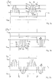
Nachfolgend werden bevorzugte Ausführungsformen der vorliegenden Erfindung anhand der beigefügten Zeichnungen beispielhaft erläutert. Es zeigen:
- Figur 1:
- einen schematischen Aufbau einer Ausführungsform eines Solarpaneels;
- Figuren 2a-d:
- die Erzeugung eines zeitlich zumindest zeitweise konstanten Gesamtausgangsstroms durch die Superposition dreier zeitlich variierender Ausgangsströme; und
- Figuren 3a-c:
- die Erzeugung eines sinusförmigen Gesamtausgangsstroms durch die Superposition zweier zeitlich variierender Ausgangsströme.
- FIG. 1:
- a schematic structure of an embodiment of a solar panel;
- FIGS. 2a-d:
- the generation of an at least temporarily constant total output current through the superposition of three time-varying output currents; and
- FIGS. 3a-c:
- the generation of a sinusoidal total output current through the superposition of two time-varying output currents.
Die Anschlußdose 7 umfaßt in dieser Ausführungsform eine Anzahl N von drei ersten elektrischen Leiterkontakten 11a bis 11 c, ein Anzahl N von drei zweiten elektrischen Leiterkontakten 12a bis 12c und eine Anzahl N von drei Stellgliedern 13a, 13b, 13c. Jedes der N Stellglieder 13a, 13b, 13c ist mit einem zugeordneten ersten elektrischen Leiterkontakt 11a, 11 b, 11 c und einem zugeordneten zweiten elektrischen Leiterkontakt 12a, 12b, 12c elektrisch verbunden.The
Die drei ersten elektrischen Leiterkontakte 11a bis 11 c sind beim betriebsgemäßen Gebrauch des Solarpaneels 1 jeweils mit einem zugeordneten elektrischen Leiter 5a, 5c, 5e des Solarmoduls 3 elektrisch kontaktiert. Mit anderen Worten ist ein erster 11a der drei ersten elektrischen Leiterkontakte mit dem ersten elektrischen Leiter 5a kontaktiert, ein zweiter 11 b der drei ersten elektrischen Leiterkontakte mit dem dritten elektrischen Leiter 5c kontaktiert und ein dritter 11f der drei ersten elektrischen Leiterkontakte mit dem fünften elektrischen Leiter 5e des Solarmoduls 3 kontaktiert.The three first electrical conductor contacts 11a to 11c are electrically contacted in the proper operation of the
Entsprechend sind die drei zweiten elektrischen Leiterkontakte 12a bis 12c beim betriebsgemäßen Gebrauch des Solarpaneels 1 jeweils mit einem zugeordneten elektrischen Leiter 5b, 5d, 5f des Solarmoduls 3 elektrisch kontaktiert. Mit anderen Worten ist ein erster 12a der drei zweiten elektrischen Leiterkontakte mit dem zweiten elektrischen Leiter 5b kontaktiert, ein zweiter 12b der drei zweiten elektrischen Leiterkontakte mit dem vierten elektrischen Leiter 5d kontaktiert und ein dritter 12f der drei zweiten elektrischen Leiterkontakte mit dem sechsten elektrischen Leiter 5f des Solarmoduls 3 kontaktiert.Correspondingly, the three second
Es versteht sich, daß die Anzahl N im Sinne der Erfindung jede natürliche Zahl größer als 1 sein kann, also insbesondere 2, 3, 4, 5, 6, 7, 8, 9, 10 usw.. Bevorzugt entspricht die Anzahl N der Stellglieder 13a, 13b, 13c der Anzahl der Solarzellengruppen 4a, 4b, 4c des Solarmoduls 3, so daß jedes der Stellglieder 13a, 13b, 13c mit einer zugeordneten Solarzellengruppe 4a, 4b, 4c des Solarmoduls 3 über die ersten Leiterkontakte 11 a bis 11 c und die zweiten Leiterkontakte 12a bis 12c elektrisch verbunden ist. Mit anderen Worten ist das erste Stellglied 13a über den ersten der ersten und zweiten elektrischen Leiterkontakte 11a, 12a mit der ersten Solarzellengruppe 4a elektrisch verbunden. Analog ist das zweite Stellglied 13b über den zweiten der ersten und zweiten elektrischen Leiterkontakte 11 b, 12b mit der zweiten Solarzellengruppe 4b und das dritte Stellglied 13c über den dritten der ersten und zweiten elektrischen Leiterkontakte 11 c, 12c mit der dritten Solarzellengruppe 4c elektrisch verbunden.It is understood that the number N in the context of the invention, any natural number may be greater than 1, ie in particular 2, 3, 4, 5, 6, 7, 8, 9, 10, etc. Preferably, the number N corresponds to the
Die Stellglieder 13a, 13b, 13c sind jeweils unmittelbar oder mittelbar über zumindest eines der Stellglieder 13a, 13b, 13c mit einem ersten 15a und zweiten 15b Anschlußpol der Anschlußdose 7 kontaktiert. Die Stellglieder 13a, 13b, 13c stellen jeweils einen elektrischen Kontakt zwischen dem ersten und zweiten Anschlußpol 15a, 15b und den Leiterkontakten 11a bis 11 c, 12a bis 12c her, welche dem jeweiligen Stellglied 13a, 13b, 13c zugeordnet sind.The
Ein von der ersten Solarzellengruppe 4a erzeugter, über die Zeit t variabler elektrischer Eingangsstrom IE [1](t), welcher über die elektrischen Leiter 5a, 5b sowie die Leiterkontakte 11a, 12a zu dem ersten Stellglied 13a und wieder zurück zur ersten Solarzellengruppe 4a fließt, wird durch das erste Stellglied 13a in einen vorbestimmbaren Ausgangsstrom IA [1](t) konvertiert, welcher ebenfalls zeitlich variabel sein kann. Analog wird ein von der zweiten Solarzellengruppe 4b erzeugter elektrischer Eingangsstrom IE [2](t), welcher über die elektrischen Leiter 5c, 5d sowie die Leiterkontakte 11 b, 12b zu dem zweiten Stellglied 13b fließt, durch das zweite Stellglied 13b in einen vorbestimmbaren Ausgangsstrom IA [2](t) konvertiert und ein von der dritten Solarzellengruppe 4c erzeugter elektrischer Eingangsstrom IE [3](t), welcher über die elektrischen Leiter 5e, 5f sowie die Leiterkontakte 11 c, 12c zu dem dritten Stellglied 13c fließt, wird durch das dritte Stellglied 13c in einen vorbestimmbaren Ausgangsstrom IA [3](t) konvertiert. Die Ausgangsströme der einzelnen Stellglieder 13a, 13b, 13c addieren sich zu einem Gesamtausgangsstrom I(t), welcher über den ersten und zweiten Anschlußpol 15a, 15b bereitgestellt werden kann. Der Gesamtausgangsstrom I(t) ist als Summe der Ausgangsströme in Abhängigkeit von der Anzahl N der Stellglieder 13a, 13b, 13c durch die Gleichung 
gegeben.An electrical input current I E [1] (t) generated by the first solar cell group 4a and variable over time t, which is supplied via the
given.
Alternativ kann eine von der ersten Solarzellengruppe 4a erzeugte elektrische Eingangsspannung UE [1](t), welche zwischen den elektrischen Leitungen 5a, 5b sowie den Leiterkontakten 11a, 12a anliegt und dem Stellglied 13a zugeführt wird, durch das Stellglied 13a in eine vorbestimmbare Ausgangsspannung UA [1](t) konvertiert werden. Dementsprechend kann eine von der zweiten Solarzellengruppe 4b erzeugte elektrische Eingangsspannung UE [2](t), welche zwischen den elektrischen Leitungen 5c, 5d sowie den Leiterkontakten 11b, 12b anliegt und dem Stellglied 13b zugeführt wird, durch das Stellglied 13b in eine vorbestimmbare Ausgangsspannung UA [2](t) konvertiert werden und eine von der dritten Solarzellengruppe 4c erzeugte elektrische Eingangsspannung UE [3](t), welche zwischen den elektrischen Leitungen 5e, 5f sowie den Leiterkontakten 11 c, 12c anliegt und dem Stellglied 13c zugeführt wird, kann durch das Stellglied 13c in eine vorbestimmbare Ausgangsspannung UA [3](t) konvertiert werden. Die Ausgangsspannungen der einzelnen Stellglieder 13a, 13b, 13c addieren sich zu einer Gesamtausgangsspannung U(t), welche ebenfalls über den ersten und zweiten Anschlußpol 15a, 15b bereitgestellt werden bzw. anliegen kann. Die Gesamtausgangsspannung U(t) ist als Summe der Ausgangsspannungen in Abhängigkeit von der Anzahl N der Stellglieder 13a, 13b, 13c durch die Gleichung 
gegeben.Alternatively, an input electric voltage U E [1] (t) generated by the first solar cell group 4a, which is applied between the
given.
Unabhängig davon, ob eine durch die Anschlußdose 7 ein vorbestimmter Gesamtausgangsstrom I(t) oder eine vorbestimmte Gesamtausgangsspannung U(t) bereitgestellt wird, können die Anschlußpole 15a, 15b vorzugsweise als Anschlußkabel oder als Verbinder ausgebildet sein.Regardless of whether a predetermined total output current I (t) or a predetermined total output voltage U (t) is provided by the
Die in der
Bevorzugt ist in der Regeleinrichtung 17 die Strom-Spannungs-Kennlinie zumindest einer der Solarzellengruppen 4a, 4b, 4c, bevorzugt jeder der Solarzellengruppen 4a, 4b, 4c, gespeichert, so daß die Regeleinrichtung 17 den Innenwiderstand zumindest eines der zugeordneten Stellglieder 13a, 13b, 13c, bevorzugt jedes der zugeordneten Stellglieder 13a, 13b, 13c, derart vorgeben kann, daß durch Einstellen des Innenwiderstandes die zugeordnete Solarzellengruppe gemäß der gespeicherten Strom-Spannungs-Kennlinie im optimalen Arbeitspunkt gehalten werden kann, um vorteilhafterweise die durch die Solarzellengruppe abgegebene elektrische Leistung zu maximieren.The current-voltage characteristic of at least one of the solar cell groups 4a, 4b, 4c, preferably each of the solar cell groups 4a, 4b, 4c, is preferably stored in the
In der in
Die Anschlußdose in der in
Vorteilhafterweise kann die Regeleinrichtung 17 eine Korrelation zwischen dem gewünschten Gesamtausgangsstrom IG(t) und dem tatsächlichen an den Anschlußpolen 15a, 15b bereitgestellten Gesamtausgangsstrom I(t) durchführen, um beispielsweise eine Korrektur derart durchzuführen, daß die Abweichung zwischen dem gewünschten und dem tatsächlichen Gesamtausgangsstrom verringert bzw. minimal wird. Dementsprechend kann die Regeleinrichtung 17 auch eine Korrelation zwischen der gewünschten Gesamtausgangsspannung UG(t) und der tatsächlich bereitgestellten Gesamtausgangsspannung U(t) durchführen. Die Rückkopplungseinrichtung 23 kann beispielsweise ein Übertrager 23 sein, welcher die Regeleinrichtung 17 induktiv mit einem der Anschlußpole 15a, 15b koppelt. Alternativ kann die Kopplung zwischen einem der Anschlußpole 15a, 15b und der Regeleinrichtung 17 auch kapazitiv oder galvanisch erfolgen, beispielsweise durch einen Kondensator, einen Widerstand oder lediglich durch eine elektrische Leitung.Advantageously, the
Um die Kommunikation über die Schnittstelle 21 und/oder die Regelung des Gesamtausgangsstroms I(t) bzw. der Gesamtausgangsspannung U(t) zu ermöglichen, kann die Regeleinrichtung 17 vorzugsweise einen Mikroprozessor 25 umfassen. Bevorzugt umfaßt die Regeleinrichtung 17 zur Erfassung der aktuellen Betriebsparameter eine Strommeßeinrichtung 27 und/oder eine Spannungsmeßeinrichtung 29 und/oder eine Temperaturmeßeinrichtung 31.In order to enable the communication via the
Beispielsweise können die aktuellen Werte der Ausgangsströme IA [n](t), des Gesamtausgangsstroms I(t), der Ausgangsspannungen UA [n](t) und/oder der Gesamtausgangsspannung U(t) mittels der Strommeßeinrichtung 27 bzw. der Spannungsmeßeinrichtung 29 erfaßt werden, um beispielsweise zur Regelung der Stellglieder 13a, 13b, 13c verwendet zu werden. Alternativ oder zusätzlich können die aktuellen Werte der externen Steuereinrichtung (nicht gezeigt) zur Verfügung gestellt werden.For example, the current values of the output currents I A [n] (t), the total output current I (t), the output voltages U A [n] (t) and / or the total output voltage U (t) can be determined by the
Die Temperaturmeßeinrichtung 31 kann beispielsweise die Betriebstemperatur der Anschlußdose 7 erfassen. Die durch die Temperaturmeßeinrichtung 31 erfaßten bzw. gemessenen Temperaturen können der Regeleinrichtung 17 bzw. der externen Steuereinrichtung bereitgestellt werden, um den Betriebszustand der Anschlußdose 7 bzw. des Solarpaneels 1 zu überwachen. Bei einer Betriebstemperatur außerhalb eines vorbestimmten Betriebstemperaturbereichs kann die Anschlußdose 7 bzw. das Solarpaneel 1 vorzugsweise mittels der externen Steuereinrichtung oder der Regeleinrichtung 17 abgeschaltet werden.The
Um die Regeleinrichtung 17 bzw. den Mikroprozessor 25 mit elektrischer Energie zu versorgen, umfaßt die Anschlußdose 7 vorzugsweise eine Stromquelle 33. Die Stromquelle 33 kann beispielsweise ein Akkumulator sein, welcher durch das Solarmodul 3 geladen wird, wenn dieses beleuchtet wird. Alternativ oder zusätzlich kann der Akkumulator mittels des über die Anschlußpole 15a, 15b fließenden Stroms geladen werden oder über eine an die Schnittstelle 21 angeschlossene Ladevorrichtung. Vorteilhafterweise kann die Regeleinrichtung 17 auch betrieben werden, wenn das Solarmodul 3 nicht beleuchtet wird bzw. wenn kein Strom über die Anschlußpole 15a, 15b fließt.In order to supply the
Die
Der in der
Die Zeitdauer des Rechteckimpulses T1 = nΔt, wobei n eine natürliche Zahl ist, und die Stromstärke IA [1](t) eines der Rechteckimpulse, welche von dem ersten Stellglied 13a bereitgestellt wird, kann beispielsweise von der Beleuchtungsintensität abhängen, welche auf die mit dem ersten Stellglied 13a elektrisch verbundenen Solarzellengruppe 4a trifft. Bei einer maximalintensiven Bestrahlung der Solarzellengruppe 4a, welche dann eine maximale Eingangsstromstärke IE [1](t) liefert, kann das Stellglied 13a beispielsweise eine konstante vorbestimmte Ausgangsstromstärke IA [1](t)=Imax liefern. Sinkt jedoch die Bestrahlungsintensität auf die Solarzellengruppe 4a, so sinkt auch die zur Verfügung stehende Eingangsstromstärke. Da das Stellglied weiterhin eine vorbestimmte Ausgangsstromstärke liefern soll, kann das Stellglied 13a statt eines konstanten Ausgangsstromes eine Folge von Rechteckimpulsen der gewünschten Stromstärke bereitstellen und zwar derart, daß die von der Solarzellengruppe 4a bereitgestellte mittlere elektrische Leistung im wesentlichen der von dem Stellglied 13a bereitgestellten elektrischen Leistung entspricht. Mit anderen Worten wird die an dem Stellglied 13a bereitgestellte elektrische Leistung gegenüber der von der Solarzellengruppe 4a erzeugten elektrischen Leistung im wesentlichen lediglich um die Verlustleistung des Stellglieds 13a gemindert. Je geringer also die von der Solarzellengruppe 4a erzeugte elektrische Leistung ist, desto kürzer kann die Zeitdauer t der vom Stellglied 13a bereitgestellten Rechteckimpulse 41 a bis 41 f bei konstanter Stromstärke sein.The duration of the rectangular pulse T 1 = nΔt, where n is a natural number, and the current intensity I A [1] (t) of one of the square pulses provided by the
Der in der
Schließlich kann der in der
Der in der
Durch die partielle Abschattung ab dem Ereigniszeitpunkt tE muß eine andere zeitliche Abfolge durch die Regeleinrichtung vorgesehen werden. Da lediglich Strom für die Dauer eines Zeitintervals von 1Δt durch das dritte Stellglied 13c bereitgestellt werden kann, werden die Zeitintervalle für die übrigen Stellglieder 13a, 13b, in welchen elektrische Energie zwischengepuffert werden kann, kürzer. Der von dem ersten Stellglied 13a bereitgestellte erste Ausgangsstrom IA [1](t) umfaßt ab dem Ereigniszeitpunkt tE Rechteckimpulse 41 d, 41 e, 41 f, welche eine Zeitdauer von 2Δt aufweisen. Während dieses Zeitintervalls trägt der erste Ausgangsstrom IA [1](t) zu dem Gesamtausgangsstrom I(t) bei. Zwischen zwei Rechteckimpulsen liegt ein Zeitintervall von 3Δt, in welchem dann der zweite Ausgangsstrom IA [2](t) einen Rechteckimpuls einer Zeitdauer von 2Δt und der dritte Ausgangsstrom IA [3](t) einen Rechteckimpuls einer Zeitdauer von 1Δt aufweist.Due to the partial shading from the event time t E another time sequence must be provided by the control device. Since only current for a time interval of 1Δt can be provided by the
Die über die Zeit t gemittelte elektrische Leistung des ersten und zweiten Ausgangsstromes sind vor und nach dem Ereigniszeitpunkt tE vorzugsweise im wesentlichen gleich groß. Jedoch sind die zeitlichen Funktionen der Ausgangsströme IA [1](t) und IA [2](t) derart angepaßt, daß die durch die Abschattung resultierende zeitliche Funktion des Ausgangsstroms IA [3](t) in der Superposition mit den zeitlichen Funktionen der übrigen Ausgangsströme einen möglichst konstanten Gesamtausgangsstrom I(t) ergibt.The electrical power of the first and second output currents averaged over time t are preferably substantially equal before and after the event time t E. However, the temporal functions of the output currents I A [1] (t) and I A [2] (t) adapted such that the resulting by the shading temporal function of the output current I A [3] (t) in the superposition with the temporal functions of the other output currents as possible constant total output current I (t).
Die
Die in den
Bevorzugt kann der zeitliche Verlauf des ersten Ausgangsstroms IA [1](t) zumindest abschnittsweise im wesentlichen der Sinusfunktion folgen. Weiter bevorzugt kann der zeitliche Verlauf des ersten Ausgangsstroms IA [1](t) wie in ![]()
![]()
In der in
Zu dem ersten Ausgangsstrom komplementär verlaufend ist der in der
Der in der
Bevorzugt beträgt die Periode T des Gesamtstroms I(t) etwa 0,020 s oder etwa 0,0167 s. Mit anderen Worten weist der Gesamtstrom I(t) eine Frequenz von etwa 50 Hz oder etwa 60 Hz auf. Die Pulslänge bzw. die Zeitdauer T1=Δt der einzelnen Rechteckimpulse ist kleiner als die Periode T. Bevorzugt ist Δt kleiner oder gleich T/2, weiter bevorzugt ist Δt kleiner oder gleich T/4, weiter bevorzugt ist Δt kleiner oder gleich T/8, besonders bevorzugt ist Δt kleiner oder gleich T/16, insbesondere ist Δt kleiner oder gleich T/32. Beispielsweise ist Δt kleiner als 10 ms, kleiner als 5 ms, kleiner als 2 ms, kleiner als 1 ms und insbesondere kleiner als 0,5 ms. Vorteilhafterweise kann der Gesamtausgangsstrom I(t) besser einer Sinusfunktion entsprechen bzw. diese approximieren, je kleiner das Zeitintervall Δt im Verhältnis zur Periode T ist.Preferably, the period T of the total current I (t) is about 0.020 s or about 0.0167 s. In other words, the total current I (t) has a frequency of about 50 Hz or about 60 Hz. The pulse length or the time duration T 1 = Δt of the individual rectangular pulses is smaller than the period T. Preferably, Δt is less than or equal to T / 2, more preferably Δt is less than or equal to T / 4, further preferably Δt is less than or equal to T / 8, more preferably Δt is less than or equal to T / 16, in particular Δt is less than or equal to T / 32. For example, Δt is less than 10 ms, less than 5 ms, less than 2 ms, less than 1 ms and in particular less than 0.5 ms. Advantageously, the smaller the time interval .DELTA.t in relation to the period T, the total output current I (t) can better correspond to or approximate a sine function.
Es versteht sich, daß ein beliebiger Gesamtausgangsstrom I(t), beispielsweise in Form eines Gleichstroms oder eines Wechselstroms, durch eine beliebige Anzahl von Ausgangsströmen superpositioniert werden kann. Das Solarpaneel bzw. die Anschlußdose muß dann eine entsprechende Anzahl von Stellgliedern und eine geeignete Regeleinrichtung aufweisen.It is understood that any total output current I (t), for example, in the form of a direct current or an alternating current, can be superposed by any number of output currents. The solar panel or junction box must then have a corresponding number of actuators and a suitable control device.
- 11
- Solarpaneelsolar panel
- 33
- Solarmodulsolar module
- 4a-4c4a-4c
- Solarzellengruppen des Solarmoduls 3Solar cell groups of the solar module 3
- 5a-5f5a-5f
- elektrischer Leiter des Solarmoduls 3electrical conductor of the solar module 3
- 77
- Anschlußdosejunction box
- 11a-1111a-11
- c erster Leiterkontaktc first conductor contact
- 12a-12c12a-12c
- zweiter Leiterkontaktsecond conductor contact
- 13a-13c13a-13c
- Stellgliedactuator
- 15a, 15b15a, 15b
- AnschlußpolA terminal
- 1717
- Regeleinrichtungcontrol device
- 1919
- Steuerleitungcontrol line
- 2121
- Schnittstelleinterface
- 2323
- RückkopplungseinrichtungFeedback means
- 2525
- Mikroprozessormicroprocessor
- 2727
- Strommeßeinrichtungcurrent measurement
- 2929
- Spannungsmeßeinrichtungvoltage measuring
- 3131
- Temperaturmeßeinrichtungtemperature measurement
- 3333
- Stromquellepower source
- 41a-41f41a-41f
- Stromimpulse des ersten AusgangsstromsCurrent pulses of the first output current
- 43a-43f43a-43f
- Stromimpulse des zweiten AusgangsstromsCurrent pulses of the second output current
- 45a-45e45a-45e
- Stromimpulse des dritten AusgangsstromsCurrent pulses of the third output current
- 51a-51j51a-51j
- Stromimpulse des ersten AusgangsstromsCurrent pulses of the first output current
- 53a-53i53a-53i
- Stromimpulse des zweiten AusgangsstromsCurrent pulses of the second output current
Claims (11)
wobei jedes der N Stellglieder (13a, 13b, 13c) mit dem ersten Anschlußpol (15a) und dem zweiten Anschlußpol (15b) elektrisch verbunden ist,
wobei jedes der N Stellglieder (13a, 13b, 13c) einen zugeordneten ersten elektrischen Leiterkontakt (11a, 11 b, 11 c) und einen zugeordneten zweiten elektrischen Leiterkontakt (12a, 12b, 12c) aufweist, und
wobei jeder der ersten elektrischen Leiterkontakte (11a, 11 b, 11 c) und jeder der zweiten elektrischen Leiterkontakte (12a, 12b, 12c) mit einem zugeordneten elektrischen Leiter (5a-5f) des Solarmoduls (3) elektrisch kontaktierbar ist;
wobei das n-te der N Stellglieder (13a, 13b, 13c) mit n ∈ [1...N] einen über eine Zeit t vorgegebenen elektrischen Eingangsstrom IE n(t), welcher über die zugeordneten ersten (11a, 11 b, 11 c) und zweiten (12a, 12b, 12c) elektrischen Leiterkontakte dem n-ten der Stellglieder (13a, 13b, 13c) zugeführt wird, in einen durch die Regeleinrichtung (17) vorbestimmbaren zeitlich variablen Ausgangsstrom IA n(t) konvertiert, so daß ein vorbestimmbarer superpositionierter Ausgangsstrom

oder
wobei das n-te der N Stellglieder (13a, 13b, 13c) mit n ∈ [1...N] eine über die Zeit t vorgegebene elektrische Eingangsspannung UE n(t), welche an den zugeordneten ersten (11a, 11 b, 11 c) und zweiten (12a, 12b, 12c) elektrischen Leiterkontakten des n-ten der N Stellglieder (13a, 13b, 13c) anliegt, in eine durch die Regeleinrichtung (17) vorbestimmbare zeitlich variable Ausgangsspannung UA n(t) konvertiert, so daß eine vorbestimmbare superpositionierte Ausgangsspannung

wherein each of the N actuators (13a, 13b, 13c) is electrically connected to the first terminal pole (15a) and the second terminal pole (15b),
wherein each of the N actuators (13a, 13b, 13c) has an associated first electrical conductor contact (11a, 11b, 11c) and an associated second electrical conductor contact (12a, 12b, 12c), and
wherein each of the first electrical conductor contacts (11a, 11b, 11c) and each of the second electrical conductor contacts (12a, 12b, 12c) is electrically contactable with an associated electrical conductor (5a-5f) of the solar module (3);
where the nth of the N actuators (13a, 13b, 13c) with n ∈ [1 ... N] has an electrical input current I E n (t) which is predetermined over a time t and which is distributed via the associated first (11a, 11b , 11 c) and second (12a, 12b, 12c) electrical conductor contacts the n-th of the actuators (13a, 13b, 13c) is supplied, in a by the control device (17) predeterminable time-variable output current I A n (t) converted such that a predeterminable superpositioned output current
or
where the nth of the N actuators (13a, 13b, 13c) with n ∈ [1 ... N] one over the time t predetermined electrical input voltage U E n (t), which at the associated first (11a, 11 b, 11 c) and second (12a, 12b, 12c) electrical conductor contacts of the n-th of the N actuators (13a, 13b, 13c) is applied, in a by the control device (17) pre-definable time-variable output voltage U A n (t) is converted, so that a predeterminable superpositioned output voltage
wobei der elektrische Verbraucher mit einem ersten Anschlußpol (15a) und einem zweiten Anschlußpol (15b) der Anschlußdose (7) elektrisch verbunden ist.Use of a junction box (7) according to any one of claims 1 to 8 for contacting an electrical load with a solar module (3), each of the first electrical conductor contacts (11 a, 11 b, 11 c) of the junction box (7) and each the second electrical conductor contacts (12a, 12b, 12c) is electrically contacted with an associated electrical conductor (5a-5d) of the solar module (3) and
wherein the electrical load is electrically connected to a first terminal pole (15a) and a second terminal pole (15b) of the junction box (7).

oder

or
Applications Claiming Priority (1)
| Application Number | Priority Date | Filing Date | Title |
|---|---|---|---|
| DE102010023085A DE102010023085A1 (en) | 2010-06-08 | 2010-06-08 | Connection box for connecting e.g. electrical direct current consumer with solar module of solar panel for generating electric power from sunlight, has actuator supplied with input voltage to generate super-positioned output voltage |
Publications (2)
| Publication Number | Publication Date |
|---|---|
| EP2437371A1 true EP2437371A1 (en) | 2012-04-04 |
| EP2437371B1 EP2437371B1 (en) | 2016-09-28 |
Family
ID=44973839
Family Applications (1)
| Application Number | Title | Priority Date | Filing Date |
|---|---|---|---|
| EP11004680.2A Active EP2437371B1 (en) | 2010-06-08 | 2011-06-08 | Connection socket, solar panel, use and method for generating a pre-defined current |
Country Status (2)
| Country | Link |
|---|---|
| EP (1) | EP2437371B1 (en) |
| DE (1) | DE102010023085A1 (en) |
Citations (3)
| Publication number | Priority date | Publication date | Assignee | Title |
|---|---|---|---|---|
| DE19635606A1 (en) * | 1996-09-02 | 1998-03-05 | Werner Prof Dr Ing Kleinkauf | Low voltage direct current to high voltage alternating current converter |
| DE102008008505A1 (en) * | 2008-02-11 | 2009-08-13 | Siemens Aktiengesellschaft | Photo voltaic-sub generator-junction box for photo voltaic-system, has electronic control unit connected with electronic circuit element to activate and deactivate associated photo voltaic-strand lines |
| WO2009146065A2 (en) * | 2008-04-04 | 2009-12-03 | Harrington Francis P | Energy interface module and power conversion system |
Family Cites Families (4)
| Publication number | Priority date | Publication date | Assignee | Title |
|---|---|---|---|---|
| DE4032569A1 (en) * | 1990-10-13 | 1992-04-16 | Flachglas Solartechnik Gmbh | Photovoltaic system coupled to mains network - has individual modules incorporating respective DC-AC converter for direct supply of mains network |
| US6198178B1 (en) * | 1999-12-21 | 2001-03-06 | International Power Systems, Inc. | Step wave power converter |
| JP2000270564A (en) * | 1999-03-15 | 2000-09-29 | Mitsubishi Electric Corp | Linking device |
| DE102006010694B4 (en) * | 2006-03-08 | 2010-01-07 | Refu Elektronik Gmbh | Inverter circuit for extended input voltage range |
-
2010
- 2010-06-08 DE DE102010023085A patent/DE102010023085A1/en not_active Ceased
-
2011
- 2011-06-08 EP EP11004680.2A patent/EP2437371B1/en active Active
Patent Citations (3)
| Publication number | Priority date | Publication date | Assignee | Title |
|---|---|---|---|---|
| DE19635606A1 (en) * | 1996-09-02 | 1998-03-05 | Werner Prof Dr Ing Kleinkauf | Low voltage direct current to high voltage alternating current converter |
| DE102008008505A1 (en) * | 2008-02-11 | 2009-08-13 | Siemens Aktiengesellschaft | Photo voltaic-sub generator-junction box for photo voltaic-system, has electronic control unit connected with electronic circuit element to activate and deactivate associated photo voltaic-strand lines |
| WO2009146065A2 (en) * | 2008-04-04 | 2009-12-03 | Harrington Francis P | Energy interface module and power conversion system |
Also Published As
| Publication number | Publication date |
|---|---|
| EP2437371B1 (en) | 2016-09-28 |
| DE102010023085A1 (en) | 2011-12-08 |
Similar Documents
| Publication | Publication Date | Title |
|---|---|---|
| EP2256823A1 (en) | Connection socket, solar panel and use of the solar panel | |
| DE3641059C2 (en) | Solar cell system | |
| EP3394948B1 (en) | Inverter having network separation point and insulation resistance measurement, and method for measuring an insulation resistance | |
| DE102010038880A1 (en) | Energy converter for outputting electrical energy | |
| DE112018004544T5 (en) | CONTROL DEVICE | |
| DE102018125272A1 (en) | Device and method for discharging an intermediate circuit capacitor, converter and vehicle | |
| DE2246505B2 (en) | Circuit arrangement for the uninterruptible power supply of a direct current consumer with constant voltage | |
| EP2437371B1 (en) | Connection socket, solar panel, use and method for generating a pre-defined current | |
| WO2018054835A1 (en) | Solar module, phovoltaic system, and voltage limitation method | |
| EP2395556B1 (en) | Connection socket, solar panel and method for generating a three phase current | |
| EP4090981B1 (en) | Method and circuit arrangement for detecting an arc, and photovoltaic (pv) inverter having a corresponding circuit arrangement | |
| EP2790290A2 (en) | Battery storage installation and method for operating a battery storage installation | |
| WO2014037297A1 (en) | Method for increasing the service life of the intermediate circuit capacitor of an electric system which has an inverter, electric system, and control unit for an electric system | |
| WO2017148602A1 (en) | Voltage converter, and electric drive system comprising a voltage converter | |
| EP3326283A1 (en) | Method for operating an inverter, inverter, and photovoltaic system | |
| DE202009007320U1 (en) | Junction box and solar panel | |
| WO2019072511A1 (en) | Method for charging an electrical energy store by means of voltage pulses | |
| EP2528217B1 (en) | Two-quadrant chopper | |
| DE19753210A1 (en) | Rechargeable electrical power source | |
| EP3827516B1 (en) | Method to use a pv device having improved overall efficiency | |
| DE102020132934B3 (en) | Controller, system and method for controlling an electro-mechanical switch assembly | |
| DE102016103782B4 (en) | Arrangement with a sensor comprising a microprocessor and a probe interface | |
| DE102020006803A1 (en) | Device for converting energy from the quantum vacuum | |
| DE102022201380A1 (en) | circuit arrangement | |
| DE102015006608B4 (en) | Method for operating a photovoltaic device of a motor vehicle and motor vehicle |
Legal Events
| Date | Code | Title | Description |
|---|---|---|---|
| PUAI | Public reference made under article 153(3) epc to a published international application that has entered the european phase |
Free format text: ORIGINAL CODE: 0009012 |
|
| AK | Designated contracting states |
Kind code of ref document: A1 Designated state(s): AL AT BE BG CH CY CZ DE DK EE ES FI FR GB GR HR HU IE IS IT LI LT LU LV MC MK MT NL NO PL PT RO RS SE SI SK SM TR |
|
| AX | Request for extension of the european patent |
Extension state: BA ME |
|
| 17P | Request for examination filed |
Effective date: 20121004 |
|
| RAP1 | Party data changed (applicant data changed or rights of an application transferred) |
Owner name: YAMAICHI ELECTRONICS DEUTSCHLAND GMBH |
|
| GRAP | Despatch of communication of intention to grant a patent |
Free format text: ORIGINAL CODE: EPIDOSNIGR1 |
|
| INTG | Intention to grant announced |
Effective date: 20160321 |
|
| GRAS | Grant fee paid |
Free format text: ORIGINAL CODE: EPIDOSNIGR3 |
|
| GRAJ | Information related to disapproval of communication of intention to grant by the applicant or resumption of examination proceedings by the epo deleted |
Free format text: ORIGINAL CODE: EPIDOSDIGR1 |
|
| GRAL | Information related to payment of fee for publishing/printing deleted |
Free format text: ORIGINAL CODE: EPIDOSDIGR3 |
|
| GRAR | Information related to intention to grant a patent recorded |
Free format text: ORIGINAL CODE: EPIDOSNIGR71 |
|
| GRAA | (expected) grant |
Free format text: ORIGINAL CODE: 0009210 |
|
| INTC | Intention to grant announced (deleted) | ||
| AK | Designated contracting states |
Kind code of ref document: B1 Designated state(s): AL AT BE BG CH CY CZ DE DK EE ES FI FR GB GR HR HU IE IS IT LI LT LU LV MC MK MT NL NO PL PT RO RS SE SI SK SM TR |
|
| INTG | Intention to grant announced |
Effective date: 20160823 |
|
| REG | Reference to a national code |
Ref country code: GB Ref legal event code: FG4D Free format text: NOT ENGLISH |
|
| REG | Reference to a national code |
Ref country code: CH Ref legal event code: EP |
|
| REG | Reference to a national code |
Ref country code: AT Ref legal event code: REF Ref document number: 833488 Country of ref document: AT Kind code of ref document: T Effective date: 20161015 |
|
| REG | Reference to a national code |
Ref country code: IE Ref legal event code: FG4D Free format text: LANGUAGE OF EP DOCUMENT: GERMAN |
|
| REG | Reference to a national code |
Ref country code: DE Ref legal event code: R096 Ref document number: 502011010759 Country of ref document: DE |
|
| REG | Reference to a national code |
Ref country code: LT Ref legal event code: MG4D |
|
| PG25 | Lapsed in a contracting state [announced via postgrant information from national office to epo] |
Ref country code: HR Free format text: LAPSE BECAUSE OF FAILURE TO SUBMIT A TRANSLATION OF THE DESCRIPTION OR TO PAY THE FEE WITHIN THE PRESCRIBED TIME-LIMIT Effective date: 20160928 Ref country code: FI Free format text: LAPSE BECAUSE OF FAILURE TO SUBMIT A TRANSLATION OF THE DESCRIPTION OR TO PAY THE FEE WITHIN THE PRESCRIBED TIME-LIMIT Effective date: 20160928 Ref country code: LT Free format text: LAPSE BECAUSE OF FAILURE TO SUBMIT A TRANSLATION OF THE DESCRIPTION OR TO PAY THE FEE WITHIN THE PRESCRIBED TIME-LIMIT Effective date: 20160928 Ref country code: NO Free format text: LAPSE BECAUSE OF FAILURE TO SUBMIT A TRANSLATION OF THE DESCRIPTION OR TO PAY THE FEE WITHIN THE PRESCRIBED TIME-LIMIT Effective date: 20161228 Ref country code: RS Free format text: LAPSE BECAUSE OF FAILURE TO SUBMIT A TRANSLATION OF THE DESCRIPTION OR TO PAY THE FEE WITHIN THE PRESCRIBED TIME-LIMIT Effective date: 20160928 |
|
| REG | Reference to a national code |
Ref country code: NL Ref legal event code: MP Effective date: 20160928 |
|
| PG25 | Lapsed in a contracting state [announced via postgrant information from national office to epo] |
Ref country code: GR Free format text: LAPSE BECAUSE OF FAILURE TO SUBMIT A TRANSLATION OF THE DESCRIPTION OR TO PAY THE FEE WITHIN THE PRESCRIBED TIME-LIMIT Effective date: 20161229 Ref country code: LV Free format text: LAPSE BECAUSE OF FAILURE TO SUBMIT A TRANSLATION OF THE DESCRIPTION OR TO PAY THE FEE WITHIN THE PRESCRIBED TIME-LIMIT Effective date: 20160928 Ref country code: NL Free format text: LAPSE BECAUSE OF FAILURE TO SUBMIT A TRANSLATION OF THE DESCRIPTION OR TO PAY THE FEE WITHIN THE PRESCRIBED TIME-LIMIT Effective date: 20160928 Ref country code: SE Free format text: LAPSE BECAUSE OF FAILURE TO SUBMIT A TRANSLATION OF THE DESCRIPTION OR TO PAY THE FEE WITHIN THE PRESCRIBED TIME-LIMIT Effective date: 20160928 |
|
| PG25 | Lapsed in a contracting state [announced via postgrant information from national office to epo] |
Ref country code: EE Free format text: LAPSE BECAUSE OF FAILURE TO SUBMIT A TRANSLATION OF THE DESCRIPTION OR TO PAY THE FEE WITHIN THE PRESCRIBED TIME-LIMIT Effective date: 20160928 Ref country code: RO Free format text: LAPSE BECAUSE OF FAILURE TO SUBMIT A TRANSLATION OF THE DESCRIPTION OR TO PAY THE FEE WITHIN THE PRESCRIBED TIME-LIMIT Effective date: 20160928 |
|
| REG | Reference to a national code |
Ref country code: FR Ref legal event code: PLFP Year of fee payment: 7 |
|
| PG25 | Lapsed in a contracting state [announced via postgrant information from national office to epo] |
Ref country code: BG Free format text: LAPSE BECAUSE OF FAILURE TO SUBMIT A TRANSLATION OF THE DESCRIPTION OR TO PAY THE FEE WITHIN THE PRESCRIBED TIME-LIMIT Effective date: 20161228 Ref country code: CZ Free format text: LAPSE BECAUSE OF FAILURE TO SUBMIT A TRANSLATION OF THE DESCRIPTION OR TO PAY THE FEE WITHIN THE PRESCRIBED TIME-LIMIT Effective date: 20160928 Ref country code: PL Free format text: LAPSE BECAUSE OF FAILURE TO SUBMIT A TRANSLATION OF THE DESCRIPTION OR TO PAY THE FEE WITHIN THE PRESCRIBED TIME-LIMIT Effective date: 20160928 Ref country code: SK Free format text: LAPSE BECAUSE OF FAILURE TO SUBMIT A TRANSLATION OF THE DESCRIPTION OR TO PAY THE FEE WITHIN THE PRESCRIBED TIME-LIMIT Effective date: 20160928 Ref country code: IS Free format text: LAPSE BECAUSE OF FAILURE TO SUBMIT A TRANSLATION OF THE DESCRIPTION OR TO PAY THE FEE WITHIN THE PRESCRIBED TIME-LIMIT Effective date: 20170128 Ref country code: SM Free format text: LAPSE BECAUSE OF FAILURE TO SUBMIT A TRANSLATION OF THE DESCRIPTION OR TO PAY THE FEE WITHIN THE PRESCRIBED TIME-LIMIT Effective date: 20160928 Ref country code: ES Free format text: LAPSE BECAUSE OF FAILURE TO SUBMIT A TRANSLATION OF THE DESCRIPTION OR TO PAY THE FEE WITHIN THE PRESCRIBED TIME-LIMIT Effective date: 20160928 Ref country code: PT Free format text: LAPSE BECAUSE OF FAILURE TO SUBMIT A TRANSLATION OF THE DESCRIPTION OR TO PAY THE FEE WITHIN THE PRESCRIBED TIME-LIMIT Effective date: 20170130 |
|
| REG | Reference to a national code |
Ref country code: DE Ref legal event code: R097 Ref document number: 502011010759 Country of ref document: DE |
|
| PG25 | Lapsed in a contracting state [announced via postgrant information from national office to epo] |
Ref country code: IT Free format text: LAPSE BECAUSE OF FAILURE TO SUBMIT A TRANSLATION OF THE DESCRIPTION OR TO PAY THE FEE WITHIN THE PRESCRIBED TIME-LIMIT Effective date: 20160928 |
|
| PG25 | Lapsed in a contracting state [announced via postgrant information from national office to epo] |
Ref country code: DK Free format text: LAPSE BECAUSE OF FAILURE TO SUBMIT A TRANSLATION OF THE DESCRIPTION OR TO PAY THE FEE WITHIN THE PRESCRIBED TIME-LIMIT Effective date: 20160928 |
|
| PLBE | No opposition filed within time limit |
Free format text: ORIGINAL CODE: 0009261 |
|
| STAA | Information on the status of an ep patent application or granted ep patent |
Free format text: STATUS: NO OPPOSITION FILED WITHIN TIME LIMIT |
|
| 26N | No opposition filed |
Effective date: 20170629 |
|
| PG25 | Lapsed in a contracting state [announced via postgrant information from national office to epo] |
Ref country code: SI Free format text: LAPSE BECAUSE OF FAILURE TO SUBMIT A TRANSLATION OF THE DESCRIPTION OR TO PAY THE FEE WITHIN THE PRESCRIBED TIME-LIMIT Effective date: 20160928 |
|
| PG25 | Lapsed in a contracting state [announced via postgrant information from national office to epo] |
Ref country code: MC Free format text: LAPSE BECAUSE OF FAILURE TO SUBMIT A TRANSLATION OF THE DESCRIPTION OR TO PAY THE FEE WITHIN THE PRESCRIBED TIME-LIMIT Effective date: 20160928 |
|
| REG | Reference to a national code |
Ref country code: CH Ref legal event code: PL |
|
| REG | Reference to a national code |
Ref country code: IE Ref legal event code: MM4A |
|
| PG25 | Lapsed in a contracting state [announced via postgrant information from national office to epo] |
Ref country code: LU Free format text: LAPSE BECAUSE OF NON-PAYMENT OF DUE FEES Effective date: 20170608 Ref country code: CH Free format text: LAPSE BECAUSE OF NON-PAYMENT OF DUE FEES Effective date: 20170630 Ref country code: IE Free format text: LAPSE BECAUSE OF NON-PAYMENT OF DUE FEES Effective date: 20170608 Ref country code: LI Free format text: LAPSE BECAUSE OF NON-PAYMENT OF DUE FEES Effective date: 20170630 |
|
| REG | Reference to a national code |
Ref country code: FR Ref legal event code: PLFP Year of fee payment: 8 |
|
| REG | Reference to a national code |
Ref country code: BE Ref legal event code: MM Effective date: 20170630 |
|
| REG | Reference to a national code |
Ref country code: AT Ref legal event code: MM01 Ref document number: 833488 Country of ref document: AT Kind code of ref document: T Effective date: 20170608 |
|
| PG25 | Lapsed in a contracting state [announced via postgrant information from national office to epo] |
Ref country code: BE Free format text: LAPSE BECAUSE OF NON-PAYMENT OF DUE FEES Effective date: 20170630 |
|
| PG25 | Lapsed in a contracting state [announced via postgrant information from national office to epo] |
Ref country code: MT Free format text: LAPSE BECAUSE OF FAILURE TO SUBMIT A TRANSLATION OF THE DESCRIPTION OR TO PAY THE FEE WITHIN THE PRESCRIBED TIME-LIMIT Effective date: 20160928 |
|
| PG25 | Lapsed in a contracting state [announced via postgrant information from national office to epo] |
Ref country code: AL Free format text: LAPSE BECAUSE OF FAILURE TO SUBMIT A TRANSLATION OF THE DESCRIPTION OR TO PAY THE FEE WITHIN THE PRESCRIBED TIME-LIMIT Effective date: 20160928 |
|
| PG25 | Lapsed in a contracting state [announced via postgrant information from national office to epo] |
Ref country code: AT Free format text: LAPSE BECAUSE OF NON-PAYMENT OF DUE FEES Effective date: 20170608 |
|
| PG25 | Lapsed in a contracting state [announced via postgrant information from national office to epo] |
Ref country code: HU Free format text: LAPSE BECAUSE OF FAILURE TO SUBMIT A TRANSLATION OF THE DESCRIPTION OR TO PAY THE FEE WITHIN THE PRESCRIBED TIME-LIMIT; INVALID AB INITIO Effective date: 20110608 |
|
| PG25 | Lapsed in a contracting state [announced via postgrant information from national office to epo] |
Ref country code: CY Free format text: LAPSE BECAUSE OF NON-PAYMENT OF DUE FEES Effective date: 20160928 |
|
| PG25 | Lapsed in a contracting state [announced via postgrant information from national office to epo] |
Ref country code: MK Free format text: LAPSE BECAUSE OF FAILURE TO SUBMIT A TRANSLATION OF THE DESCRIPTION OR TO PAY THE FEE WITHIN THE PRESCRIBED TIME-LIMIT Effective date: 20160928 |
|
| PG25 | Lapsed in a contracting state [announced via postgrant information from national office to epo] |
Ref country code: TR Free format text: LAPSE BECAUSE OF FAILURE TO SUBMIT A TRANSLATION OF THE DESCRIPTION OR TO PAY THE FEE WITHIN THE PRESCRIBED TIME-LIMIT Effective date: 20160928 |
|
| PGFP | Annual fee paid to national office [announced via postgrant information from national office to epo] |
Ref country code: DE Payment date: 20220901 Year of fee payment: 13 |
|
| PGFP | Annual fee paid to national office [announced via postgrant information from national office to epo] |
Ref country code: GB Payment date: 20230621 Year of fee payment: 13 |
|
| PGFP | Annual fee paid to national office [announced via postgrant information from national office to epo] |
Ref country code: FR Payment date: 20230724 Year of fee payment: 13 |