EP2413485A1 - System for supplying an alternating current charge from an AC grid with no transformer between the grid and the supply system, and power transmission chain including such a system - Google Patents
System for supplying an alternating current charge from an AC grid with no transformer between the grid and the supply system, and power transmission chain including such a system Download PDFInfo
- Publication number
- EP2413485A1 EP2413485A1 EP11305988A EP11305988A EP2413485A1 EP 2413485 A1 EP2413485 A1 EP 2413485A1 EP 11305988 A EP11305988 A EP 11305988A EP 11305988 A EP11305988 A EP 11305988A EP 2413485 A1 EP2413485 A1 EP 2413485A1
- Authority
- EP
- European Patent Office
- Prior art keywords
- rectifier
- voltage
- inverter
- alternating
- load
- Prior art date
- Legal status (The legal status is an assumption and is not a legal conclusion. Google has not performed a legal analysis and makes no representation as to the accuracy of the status listed.)
- Granted
Links
- 230000005540 biological transmission Effects 0.000 title abstract 2
- 238000004804 winding Methods 0.000 claims description 30
- 239000003990 capacitor Substances 0.000 claims description 15
- 230000008878 coupling Effects 0.000 claims description 9
- 238000010168 coupling process Methods 0.000 claims description 9
- 238000005859 coupling reaction Methods 0.000 claims description 9
- 230000003071 parasitic effect Effects 0.000 claims description 9
- 230000007935 neutral effect Effects 0.000 abstract description 20
- 238000013016 damping Methods 0.000 description 12
- XEEYBQQBJWHFJM-UHFFFAOYSA-N Iron Chemical compound [Fe] XEEYBQQBJWHFJM-UHFFFAOYSA-N 0.000 description 6
- 238000010586 diagram Methods 0.000 description 6
- 230000004048 modification Effects 0.000 description 5
- 238000012986 modification Methods 0.000 description 4
- 230000006870 function Effects 0.000 description 3
- 229910052742 iron Inorganic materials 0.000 description 3
- 244000045947 parasite Species 0.000 description 2
- 230000002457 bidirectional effect Effects 0.000 description 1
- 235000021183 entrée Nutrition 0.000 description 1
- 238000001914 filtration Methods 0.000 description 1
- 230000010365 information processing Effects 0.000 description 1
- 238000009413 insulation Methods 0.000 description 1
- 238000004513 sizing Methods 0.000 description 1
- 230000001360 synchronised effect Effects 0.000 description 1
Images


Classifications
-
- H—ELECTRICITY
- H02—GENERATION; CONVERSION OR DISTRIBUTION OF ELECTRIC POWER
- H02M—APPARATUS FOR CONVERSION BETWEEN AC AND AC, BETWEEN AC AND DC, OR BETWEEN DC AND DC, AND FOR USE WITH MAINS OR SIMILAR POWER SUPPLY SYSTEMS; CONVERSION OF DC OR AC INPUT POWER INTO SURGE OUTPUT POWER; CONTROL OR REGULATION THEREOF
- H02M5/00—Conversion of ac power input into ac power output, e.g. for change of voltage, for change of frequency, for change of number of phases
- H02M5/40—Conversion of ac power input into ac power output, e.g. for change of voltage, for change of frequency, for change of number of phases with intermediate conversion into dc
- H02M5/42—Conversion of ac power input into ac power output, e.g. for change of voltage, for change of frequency, for change of number of phases with intermediate conversion into dc by static converters
- H02M5/44—Conversion of ac power input into ac power output, e.g. for change of voltage, for change of frequency, for change of number of phases with intermediate conversion into dc by static converters using discharge tubes or semiconductor devices to convert the intermediate dc into ac
- H02M5/453—Conversion of ac power input into ac power output, e.g. for change of voltage, for change of frequency, for change of number of phases with intermediate conversion into dc by static converters using discharge tubes or semiconductor devices to convert the intermediate dc into ac using devices of a triode or transistor type requiring continuous application of a control signal
- H02M5/458—Conversion of ac power input into ac power output, e.g. for change of voltage, for change of frequency, for change of number of phases with intermediate conversion into dc by static converters using discharge tubes or semiconductor devices to convert the intermediate dc into ac using devices of a triode or transistor type requiring continuous application of a control signal using semiconductor devices only
- H02M5/4585—Conversion of ac power input into ac power output, e.g. for change of voltage, for change of frequency, for change of number of phases with intermediate conversion into dc by static converters using discharge tubes or semiconductor devices to convert the intermediate dc into ac using devices of a triode or transistor type requiring continuous application of a control signal using semiconductor devices only having a rectifier with controlled elements
-
- H—ELECTRICITY
- H02—GENERATION; CONVERSION OR DISTRIBUTION OF ELECTRIC POWER
- H02M—APPARATUS FOR CONVERSION BETWEEN AC AND AC, BETWEEN AC AND DC, OR BETWEEN DC AND DC, AND FOR USE WITH MAINS OR SIMILAR POWER SUPPLY SYSTEMS; CONVERSION OF DC OR AC INPUT POWER INTO SURGE OUTPUT POWER; CONTROL OR REGULATION THEREOF
- H02M7/00—Conversion of ac power input into dc power output; Conversion of dc power input into ac power output
- H02M7/42—Conversion of dc power input into ac power output without possibility of reversal
- H02M7/44—Conversion of dc power input into ac power output without possibility of reversal by static converters
- H02M7/48—Conversion of dc power input into ac power output without possibility of reversal by static converters using discharge tubes with control electrode or semiconductor devices with control electrode
- H02M7/53—Conversion of dc power input into ac power output without possibility of reversal by static converters using discharge tubes with control electrode or semiconductor devices with control electrode using devices of a triode or transistor type requiring continuous application of a control signal
- H02M7/537—Conversion of dc power input into ac power output without possibility of reversal by static converters using discharge tubes with control electrode or semiconductor devices with control electrode using devices of a triode or transistor type requiring continuous application of a control signal using semiconductor devices only, e.g. single switched pulse inverters
- H02M7/5387—Conversion of dc power input into ac power output without possibility of reversal by static converters using discharge tubes with control electrode or semiconductor devices with control electrode using devices of a triode or transistor type requiring continuous application of a control signal using semiconductor devices only, e.g. single switched pulse inverters in a bridge configuration
- H02M7/53871—Conversion of dc power input into ac power output without possibility of reversal by static converters using discharge tubes with control electrode or semiconductor devices with control electrode using devices of a triode or transistor type requiring continuous application of a control signal using semiconductor devices only, e.g. single switched pulse inverters in a bridge configuration with automatic control of output voltage or current
- H02M7/53875—Conversion of dc power input into ac power output without possibility of reversal by static converters using discharge tubes with control electrode or semiconductor devices with control electrode using devices of a triode or transistor type requiring continuous application of a control signal using semiconductor devices only, e.g. single switched pulse inverters in a bridge configuration with automatic control of output voltage or current with analogue control of three-phase output
- H02M7/53876—Conversion of dc power input into ac power output without possibility of reversal by static converters using discharge tubes with control electrode or semiconductor devices with control electrode using devices of a triode or transistor type requiring continuous application of a control signal using semiconductor devices only, e.g. single switched pulse inverters in a bridge configuration with automatic control of output voltage or current with analogue control of three-phase output based on synthesising a desired voltage vector via the selection of appropriate fundamental voltage vectors, and corresponding dwelling times
-
- H—ELECTRICITY
- H02—GENERATION; CONVERSION OR DISTRIBUTION OF ELECTRIC POWER
- H02M—APPARATUS FOR CONVERSION BETWEEN AC AND AC, BETWEEN AC AND DC, OR BETWEEN DC AND DC, AND FOR USE WITH MAINS OR SIMILAR POWER SUPPLY SYSTEMS; CONVERSION OF DC OR AC INPUT POWER INTO SURGE OUTPUT POWER; CONTROL OR REGULATION THEREOF
- H02M1/00—Details of apparatus for conversion
- H02M1/12—Arrangements for reducing harmonics from ac input or output
- H02M1/123—Suppression of common mode voltage or current
Definitions
- the invention also relates to a drive chain adapted to be connected to an alternating electric network, comprising an electric machine and such a power supply system of the AC electric machine.
- Document is known US 2007/0211501 A1 a feeding system of the aforementioned type.
- the system comprises a three-phase rectifier connected to a three-phase supply network, a three-phase inverter connected at the output of the rectifier and intended to supply a three-phase load.
- the network is connected to an electrical ground.
- the rectifier and the inverter are interconnected by means of a continuous bus, and the system further comprises a homopolar inductance for limiting the common-mode current, the homopolar inductance being arranged on the continuous link bus between the rectifier and the inverter.
- the power system further comprises two common mode filters respectively connected to the input of the rectifier and the output of the inverter.
- the object of the invention is to propose a system for supplying an AC electric current load making it possible to limit the homopolar voltage, while not generating additional costs.
- the object of the invention is a power supply system of the above-mentioned type, characterized in that the control device is able to limit the absolute value of the voltage between the electrical ground and a phase of the alternating current delivered to the ground. charging, in the absence of overvoltages in the load, to a first limit value strictly lower than that of the DC bus voltage.
- the invention also relates to a drive chain capable of being connected to an alternating electric network, of the type comprising an electric machine and a system for supplying the electric machine with alternating electric current from the reciprocating network, characterized in that what the power system is as defined above.
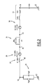
- a drive chain 10 connected to an alternating electrical network 12, comprises an electric machine 14 and a system 16 for supplying the machine with alternating electric current.
- the electrical network 12 is able to deliver an alternating electric current comprising at least one phase, and comprises a neutral point 18.
- the network 12 is a three-phase network.
- the electric machine 14 has a leakage inductance Lfm, a resistance Rm and a parasitic capacitance Cm ( figure 2 ).
- the electric machine 14 is, for example, a three-phase electric motor, and has a neutral point 19.
- the electric motor 14 is, for example, a synchronous motor. In a variant, the motor 14 is an asynchronous motor.
- the power supply system 16 comprises a device 20 for connecting the AC power supply to an electrical ground 22, a filter 24 connected to the AC mains, a rectifier 26 connected at the output of the filter, and a first device 28 for controlling the rectifier.
- the power supply system 16 also comprises an inverter 30 connected at the output of the rectifier via a DC bus 31 of voltage Vdc, a second device 32 for controlling the inverter, and a device 34 for limiting the common-mode current able to flow. between the network 12 and the machine 14.
- the power supply system 16 has no return link between the output of the inverter 30 and the input of the rectifier 26, or between the output of the inverter 30 and the input of the filter 24.
- the connection device 20 comprises a capacitor 36 of capacitance Cgh and an impedance resistor 38 Rgh, connected in parallel with the capacitor 36.
- the connecting device 20 is also called a setting device. Earth.
- the connecting device 20 is connected to the neutral point 18 of the network.
- the capacitance Cgh of the connecting device is greater than the parasitic capacitance Cm of the electric machine.
- the value of the capacitance Cgh is, for example, twenty times greater, preferably forty times, than that of the parasitic capacitance Cm.
- the filter 24 comprises, for each phase of the alternating current supplied by the network, an electromagnetic coil 40 of inductance Lf_filter, visible on the figure 2 .
- the rectifier 26 is connected to the network 12 without the presence of a transformer between it and the reciprocating network 12.
- the rectifier 26 is able to convert the alternating current supplied by the network 12 into a direct current delivered at the output of the rectifier.
- the rectifier 26 is a controlled rectifier, also called AFE (Active Front End English). It comprises an input terminal 42 for each phase of the alternating current supplied by the network 12, two output terminals 44 and an output mid-point 45.
- the rectifier 26 is, for example, a three-phase rectifier, and comprises three terminals. entry 42.
- the rectifier 26 has a neutral clamp type topology, also known as the Neutral Point Clamped (NPC) topology, and includes two switching branches 46 for each phase of said alternating current. Each switching branch is connected between a respective input terminal 42 and the corresponding output terminal 44. Each switching branch 46 comprises, for example, two controllable electronic switches 48 connected in series and interconnected by an intermediate point 50. For each phase of the alternating current, the intermediate point 50 of a switching branch 46 is connected to the point 45 through a first diode 52 connected in reverse, the intermediate point 50 of the other switching branch 46 being connected to the midpoint 45 via a second diode 54 connected in the forward direction.
- NPC Neutral Point Clamped
- the switching module 26 has a topology of the type controlled by the neutral, also called the NPP (Neutral Point Piloted) topology.
- the switching module 26 then comprises two extreme branches and an intermediate branch, also called transverse branch. Each end branch is connected between a respective input terminal and the corresponding output terminal, and includes a controllable electronic switch.
- the intermediate branch is connected between a respective input terminal and the midpoint, and has two switches connected in anti-series.
- Each controllable electronic switch 48 is, for example, bidirectional current and voltage, and comprises a transistor 56 and a diode 58 connected in antiparallel transistor.
- the transistor 56 is, for example, an IGBT transistor of the English Insulated Gate Bipolar Transistor.
- the rectifier 26 has a VHAFE homopolar voltage, visible on the figure 2 , between its input and output terminals.
- the first control device 28 comprises an information processing unit formed, for example, of a data processor 60 associated with a memory 62.
- the memory 62 is able to store a software 64 for calculating switch control signals. 48 according to a pulse width modulation, software 66 for modifying the pulse width modulation, and software 66 for applying the control signals to the switches 48 of the rectifier.
- the software of modification 66 is capable of modifying the pulse width modulation according to a control law prohibiting at least one switching state of the rectifier 26 with respect to a predetermined modulation of pulse width according to a control law allowing all the switching states of the rectifier 26.
- the first control device 28 is able to limit the absolute value of the voltage between the electric mass 22 and a phase of the alternating current delivered to the machine 14, in the absence of overvoltages in the machine 14, to a first limit value strictly less than that of the voltage Vdc of the DC bus 31.
- the first limit value is preferably equal to two thirds of that of the voltage Vdc of the DC bus 31.
- the first control device 28 is able to limit the absolute value of the voltage between the electrical ground 22 and a phase of the alternating current delivered to the machine 14 to a second limit value equal to 120% of the first limit value.
- the first control device 28 is able to limit the absolute value of the homopolar voltage VhAFE to a value less than or equal to one sixth of that of the voltage Vdc of the DC bus 31.
- the inverter 30 has two input terminals 70, an input midpoint 72, and an output terminal 74 for each phase of the alternating current delivered to the machine 14.
- the inverter 30 has clean controllable electronic switches. converting the direct current supplied by the rectifier 26 into an alternating current delivered to the machine 14 connected to its output.
- the inverter 30 is, for example, a three-level inverter.
- the inverter 30 is, for example, a neutral clamped inverter, also called inverter NPC (English Neutral Point Clamped).
- the inverter 30 is a neutral driven inverter, also called NPP inverter (English Neutral Point Piloted).
- the DC bus 31 comprises two first capacitors 76 and two second capacitors 77.
- the first two capacitors 76 are connected in series between the two output terminals 44 of the rectifier and connected to each other by a midpoint connected to the output mid-point 45 of the rectifier.
- the second capacitors 77 are connected in series between the input terminals 70 of the inverter and interconnected by a midpoint 79 connected to the input midpoint 72 of the inverter.
- the DC bus 31 has the DC voltage Vdc between the two output terminals 44 of the rectifier, and also between the two input terminals 70 of the inverter.
- the second control device 32 comprises, in a manner known per se, means for calculating the control signals of the switches of the inverter 30. pulse width modulation function and means for applying the control signals to the inverter switches 30.
- the limiting device 34 is connected between the rectifier 26 and the inverter 30. More specifically, the limitation device 34 is connected between the first capacitors 76 and the second capacitors 78, in parallel with the output terminals 44 of the rectifier, d. on the one hand, and input terminals 70 of the inverter, on the other hand.
- the limitation device 34 comprises a primary electromagnetic winding 80 for each of the two polarities of the direct current able to flow between the rectifier 26 and the inverter 30, and a core 82 for magnetic coupling of the two primary windings.
- the limiting device 34 also comprises a secondary winding 84 connected in series with an impedance resistor 86 Rh, called a damping resistor, and a second magnetic core 88 for coupling the secondary winding with the primary windings.
- the primary windings 80 have an inductance Lh, visible on the figure 2 .
- the limiting device 34 comprises a single magnetic coupling core of the two primary windings and the secondary winding.
- the damping resistor is connected directly in parallel with the primary electromagnetic winding 80.
- the damping resistor is formed by the resistance equivalent to the iron losses of the core.
- the homopolar equivalent diagram of the drive chain 10 comprises successively from the neutral point 18 of the network to the neutral point 19 of the machine, the leakage impedance Lf_filtre of the filter 24, the VHAFE homopolar voltage of the rectifier 26, homopolar inductance Lh and the damping resistor Rh connected in parallel with the homopolar inductance of the limiting device 34, the homopolar voltage VHINV of the inverter 30, and the leakage inductance Lfm and the resistance Rm of the electrical machine 14.
- the electrical grounding device 20 connected between the neutral 18 of the network and the electrical ground 22 has the capacitance Cgh in parallel with the resistor Rgh.
- the parasitic capacitance Cm of the machine is arranged between the neutral point 19 of the machine and the electrical ground 22.
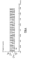
- the figure 3 represents, for each phase U, V, W of the alternating current supplied by the network 12, the voltages respectively of the network 12, the rectifier 26, the inverter 30 and the machine 14. Given the switching frequencies of the rectifier 26 and the inverter 30, the capacitance Cgh of the grounding device is assimilated to a wire.
- the homopolar inductance Lh is not represented on the figure 3 , the overvoltages on the machine 14 not being taken into account as a first approximation. So he is considered that the output midpoint 45 of the rectifier is connected by a wire to the input midpoint 72 of the inverter.
- the voltages of the network 12 are respectively denoted Vu_net, Vv_net, Vw_net.
- the voltages between each of the phases U, V, W and the rectifier output mid-point 45 are respectively denoted Vu0AFE, Vv0AFE and Vw0AFE, the voltage between each of the U, V, W phases of the rectifier and the electrical mass 22 being noted respectively.
- VuAFE, VvAFE, VwAFE the voltages of the network 12 are respectively denoted Vu_net, Vv_net, Vw_net.
- VON ' The voltage between the mid-point of the DC bus 31 and the electrical ground 22 is denoted VON ', and corresponds to the voltage between the output mid-point 45 of the rectifier and the electrical ground 22, or to the voltage between the midpoint d input 72 of the inverter and the electric ground 22.
- the voltage between the input midpoint 72 and each of the U, V, W phases of the inverter 30 is respectively denoted Vu0INV, Vv0INV, Vw0INV.
- VuM The voltage between each of the U, V, W phases of the machine 14 and the electrical ground 22 is respectively denoted by VuM, VvM and VwM.
- the maximum value of the voltage Vu0INV, Vv0INV, Vw0INV between a respective phase U, V, W and the input midpoint 72 of the inverter is equal to half of the voltage Vdc of the DC bus 31, by the intrinsic operation of any inverter, this value not being modifiable.
- the limitation in absolute value of the homopolar voltage VhAFE is obtained by modifying the pulse width modulation (PWM) of the first control device 28, in order to prohibit at least one switching state of the rectifier 26 with respect to a predetermined modulation pulse width according to a control law allowing all the switching states of the rectifier 26.
- PWM pulse width modulation
- the predetermined modulation of pulse width is, for example, a generalized discontinuous pulse width modulation, also called GDPWM (Generalized Discontinuous PWM).
- the absolute value of the homopolar voltage VhAFE must be less than or equal to one sixth of the value of the voltage Vdc of the DC bus 31, according to the preceding equations.
- the modification software 66 modifies the pulse width modulation in order to prohibit the switching states 0, 7, 16, 18, 20, 21, 23 and 25 with respect to a predetermined modulation of width pulse permitting all switching states 0 to 26 in the exemplary embodiment of the rectifier 26 at three levels.
- the modification of the pulse width modulation is obtained by modifying the reference curve, the carrier remaining identical.
- the reference curve is modified so that the rectifier 26 remains, in the case of a forbidden switching state, in the state of switching temporarily precedes the prohibited switching state according to the predetermined modulation of pulse width, during the duration of the forbidden switching state as defined by the predetermined pulse width modulation.
- the reference curve is modified so that the rectifier 26 switches, in the event of a prohibited switching state, to the switching state that follows the time delay of the prohibited switching state according to the predetermined modulation of the pulse width, during the duration of the forbidden switching state as defined by the predetermined modulation of pulse width.
- the curve 100 represents the homopolar voltage VhAFE obtained after modification of the pulse width modulation.
- the homopolar voltage VhAFE is well below or equal, in absolute value, to one sixth of the value of the DC voltage Vdc of the bus 31.
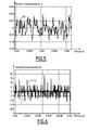
- FIGs 5 to 7 illustrate the results obtained by simulating a training chain 10 according to the embodiment of the invention.
- figure 1 with an electrical network 12 having a nominal voltage of amplitude equal to 6.6 kV and a nominal frequency of 60 Hz.
- the curve 105 represents the homopolar voltage at the terminals of the grounding device 20 per unit (pu) of the nominal voltage of the network 12.
- the curve 105 therefore represents the zero-sequence voltage between the electrical ground 22 and the neutral 18 of the network. , and said zero-sequence voltage is less than 5% of the rated voltage of the network 12 in peak value.
- the homopolar current flowing between the grounding device 20 and the neutral 18 of the electrical network has a low value intensity, represented by the curve 110.
- the effective value, or RMS value (Root Mean Square) the intensity of the homopolar current is less than 5 A, which avoids any risk of damage to the magnetic parts of the machine 14.
- the curve 115 represents the voltage VuM, VvM, VwM between the electric mass 22 and a respective phase U, V, W of the alternating current delivered to the machine 14 without taking into account the overvoltages in said machine, the curve 120 representing the same voltage VuM, VvM, VwM taking into account said overvoltages.
- the voltage VuM, VvM, VwM is less, in absolute value, two thirds of the value of the voltage Vdc of the DC bus 31, the thresholds 125, 130 in dotted lines respectively representing two thirds of the value of the voltage Vdc and at least two thirds of the value of the voltage Vdc.
- the first limit value is equal to two thirds of the value of the voltage Vdc of the DC bus 31.
- the voltage VuM, VvM, VwM is less, in absolute value, than 120% of the first limit value equal to two thirds of the value of the voltage Vdc, the thresholds 140, 145 in phantom representing respectively 120% of two thirds of the value of the voltage Vdc and 120% of at least two thirds of the value of the voltage Vdc.
- the second limit value is equal to 120% of the first limit value.
- the power supply system 16 makes it possible to limit the homopolar voltage, while not requiring the presence of a transformer between the network 12 and the rectifier 26, which does not generate additional costs. This also makes it possible to reduce the mechanical bulk of the power supply system 16 with respect to a power supply system with common mode filters connected by an electrical connection for passing the common-mode current, or also with respect to a control system. power supply with a transformer between the network and the rectifier.
- the power supply system 16 does not have a return link between the output of the inverter 30 and the input of the rectifier 26, or between the output of the inverter 30 and the input of the inverter. 24. This also reduces the mechanical size of the power system 16, as well as its cost.
- the value of the homopolar voltage between the electrical ground 22 and the neutral 18 of the network is less than 5% of the nominal voltage of the network 12 in peak value, because of the capacitor 36 having a capacitance Cgh greater than the parasitic capacitance. Cm of the electric machine.
- the power supply system 16 will therefore not disturb, in terms of insulation voltage, another equipment directly connected to the electrical network 12.
- the overvoltages in the machine 14 are damped and limited by the presence of the resistor 86 of the limiting device, also called the damping resistor.
- the controlled rectifier 26 makes it possible to reduce the harmonic rate on the network 12 and to regulate the voltage Vdc of the DC bus, as well as the power factor of the drive chain 10.
- the controlled rectifier 26 also makes it possible to regenerate on the network 12 of the electrical energy from the electric machine 14, in case of braking thereof.
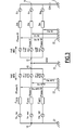
- FIG 8 illustrates a second embodiment of the invention for which elements similar to the first embodiment, described above, are identified by identical references, and are therefore not described again.
- the limiting device 34 is connected to the input of the rectifier 26.
- the limiting device 34 comprises an electromagnetic winding 200, for each phase of the alternating current of the network 12, as well as a coupling core 201 of the magnetic windings when the network 12 is a polyphase network.
- the limitation device 34 also comprises a secondary winding 202 connected in series with a resistor 203 of impedance Rh, called the damping resistor, the secondary winding 202 being magnetically coupled to the primary windings 200 via the coupling core 201.
- the damping resistor is connected directly in parallel with the primary electromagnetic winding 80.
- the damping resistor is formed by the resistance equivalent to the iron losses of the core.
- the output terminals 44, and respectively the mid-point of exit 45, of the rectifier are then directly connected to the input terminals 70, and respectively to the input midpoint 72, of the inverter.
- the DC bus 31 comprises two capacitors 204 connected in series between the output terminals 44 or between the input terminals 70, the two capacitors 204 being interconnected by a midpoint 206 connected to the midpoints 45, 72.
- FIG 9 illustrates a third embodiment of the invention for which elements similar to the first embodiment, described above, are identified by identical references, and are therefore not described again.
- the limitation device 34 is connected at the output of the inverter 30.
- the limitation device 34 comprises an electromagnetic winding 300, for each phase of the alternating current delivered to the machine 14, as well as a core 301 coupling of the magnetic windings when the electric machine 14 is a polyphase machine.
- the limitation device 34 also comprises a secondary winding 302 connected in series with a resistor 303 of impedance Rh, the secondary winding 302 being magnetically coupled to the primary windings 300 via the coupling core 301.
- the damping resistor is connected directly in parallel with the primary electromagnetic winding 80.
- the damping resistor is formed by the resistance equivalent to the iron losses of the core.
- the output terminals 44, and respectively the mid-point of exit 45, of the rectifier are then directly connected to the input terminals 70, and respectively to the input midpoint 72, of the inverter.
- the DC bus 31 comprises two capacitors 304 connected in series between the output terminals 44 or between the input terminals 70, the two capacitors 304 being interconnected by a midpoint 306 connected to the midpoints 45, 72.
Abstract
Description
La présente invention concerne un système d'alimentation d'une charge en courant électrique alternatif à partir d'un réseau électrique alternatif, du type comprenant :
- un dispositif de liaison du réseau électrique alternatif à une masse électrique,
- un redresseur connecté au réseau électrique alternatif, sans présence d'un transformateur entre le réseau alternatif et le redresseur, le redresseur comportant des interrupteurs électroniques commandables propres à convertir le courant alternatif fourni par le réseau électrique en un courant continu délivré en sortie du redresseur,
- un dispositif de commande des interrupteurs électroniques du redresseur propre à envoyer des signaux de commande aux interrupteurs respectifs,
- un onduleur connecté en sortie du redresseur via un bus continu et propre à convertir le courant continu fourni par le redresseur en un courant alternatif délivré à la charge reliée à sa sortie, et
- un dispositif de limitation du courant de mode commun propre à circuler entre le réseau et la charge.
- a device for connecting the alternating electric network to an electrical ground,
- a rectifier connected to the alternating electric network, without the presence of a transformer between the reciprocating network and the rectifier, the rectifier comprising controllable electronic switches capable of converting the alternating current supplied by the electrical network into a direct current delivered at the output of the rectifier,
- a device for controlling the electronic switches of the rectifier capable of sending control signals to the respective switches,
- an inverter connected at the output of the rectifier via a continuous bus and suitable for converting the direct current supplied by the rectifier into an alternating current delivered to the load connected to its output, and
- a common mode current limiting device adapted to flow between the network and the load.
L'invention concerne également une chaîne d'entraînement propre à être reliée à un réseau électrique alternatif, comprenant une machine électrique et un tel système d'alimentation de la machine électrique en courant alternatif.The invention also relates to a drive chain adapted to be connected to an alternating electric network, comprising an electric machine and such a power supply system of the AC electric machine.
On connaît du document
Toutefois, un tel système d'alimentation nécessite la présence de deux filtres de mode commun, afin de limiter la tension homopolaire, les filtres de mode commun étant reliés entre eux par une liaison électrique de passage du courant de mode commun. La liaison de passage du courant de mode commun comporte une résistance d'amortissement. Ceci engendre des surcoûts. En outre, le dimensionnement de tels filtres de mode commun pour le filtrage des composantes de mode commun est complexe, ces filtres ayant également une influence sur des composantes de mode différentiel du système.However, such a power supply system requires the presence of two common mode filters, in order to limit the homopolar voltage, the common mode filters being connected to each other by an electrical connection for passing the common mode current. The common mode current pass link has a damping resistor. This generates additional costs. In addition, the sizing of such common mode filters for the filtering of the common mode components is complex, these filters also having an influence on differential mode components of the system.
Le but de l'invention est de proposer un système d'alimentation d'une charge en courant électrique alternatif permettant de limiter la tension homopolaire, tout en n'engendrant pas de surcoûts.The object of the invention is to propose a system for supplying an AC electric current load making it possible to limit the homopolar voltage, while not generating additional costs.
A cet effet, l'invention a pour objet un système d'alimentation du type précité, caractérisé en ce que le dispositif de commande est propre à limiter la valeur absolue de la tension entre la masse électrique et une phase du courant alternatif délivré à la charge, en l'absence de surtensions dans la charge, à une première valeur limite strictement inférieure à celle de la tension du bus continu.For this purpose, the object of the invention is a power supply system of the above-mentioned type, characterized in that the control device is able to limit the absolute value of the voltage between the electrical ground and a phase of the alternating current delivered to the ground. charging, in the absence of overvoltages in the load, to a first limit value strictly lower than that of the DC bus voltage.
Suivant d'autres modes de réalisation, le système d'alimentation comprend une ou plusieurs des caractéristiques suivantes, prises isolément ou suivant toutes les combinaisons techniquement possibles :
- la première valeur limite est égale à deux tiers de celle de la tension du bus continu ;
- le dispositif de commande est propre à limiter la valeur absolue de la tension entre la masse électrique et une phase du courant alternatif délivré à la charge, en présence de surtensions dans la charge, à une deuxième valeur limite égale à 120% de la première valeur limite ;
- le redresseur présente une tension homopolaire, et le dispositif de commande est propre à limiter la valeur absolue de la tension homopolaire à une valeur inférieure ou égale à un sixième de celle de la tension du bus continu ;
- le dispositif de commande comporte des moyens de calcul des signaux de commande en fonction d'une modulation de largeur d'impulsion, des moyens de modification de la modulation de largeur d'impulsion suivant une loi de commande interdisant au moins un état de commutation du redresseur par rapport à une modulation prédéterminée de largeur d'impulsion suivant une loi de commande autorisant tous les états de commutation du redresseur, et des moyens pour appliquer les signaux de commande aux interrupteurs du redresseur ;
- le dispositif de limitation est connecté en entrée du redresseur ;
- le dispositif de limitation est connecté en sortie de l'onduleur ;
- le dispositif de limitation comporte un enroulement électromagnétique pour chaque phase du courant alternatif respectif ;
- le dispositif de limitation est connecté entre le redresseur et l'onduleur ;
- le dispositif de limitation comporte un enroulement électromagnétique primaire pour chacune des deux polarités du courant continu propre à circuler entre le redresseur et l'onduleur ; et
- le dispositif de limitation comporte un enroulement secondaire connecté en série avec une résistance, un noyau magnétique de couplage de l'enroulement secondaire avec les enroulements primaires.
- the first limit value is two-thirds of that of the DC bus voltage;
- the control device is adapted to limit the absolute value of the voltage between the electrical ground and a phase of the alternating current delivered to the load, in the presence of overvoltages in the load, to a second limit value equal to 120% of the first value. limit ;
- the rectifier has a homopolar voltage, and the control device is able to limit the absolute value of the homopolar voltage to a value less than or equal to one sixth of that of the DC bus voltage;
- the control device comprises means for calculating the control signals as a function of a pulse width modulation, means for modifying the pulse width modulation according to a control law prohibiting at least one switching state of the rectifier with respect to a predetermined modulation of pulse width according to a control law allowing all the switching states of the rectifier, and means for applying the control signals to the switches of the rectifier;
- the limiting device is connected to the input of the rectifier;
- the limiting device is connected at the output of the inverter;
- the limiting device comprises an electromagnetic winding for each phase of the respective alternating current;
- the limiting device is connected between the rectifier and the inverter;
- the limiting device comprises a primary electromagnetic winding for each of the two polarities of the direct current adapted to flow between the rectifier and the inverter; and
- the limiting device comprises a secondary winding connected in series with a resistor, a magnetic coupling core of the secondary winding with the primary windings.
L'invention a également pour objet une chaîne d'entraînement propre à être reliée à un réseau électrique alternatif, du type comprenant une machine électrique et un système d'alimentation de la machine électrique en courant électrique alternatif à partir du réseau alternatif, caractérisé en ce que le système d'alimentation est tel que défini ci-dessus.The invention also relates to a drive chain capable of being connected to an alternating electric network, of the type comprising an electric machine and a system for supplying the electric machine with alternating electric current from the reciprocating network, characterized in that what the power system is as defined above.
Suivant un autre mode de réalisation, la chaîne d'entraînement comprend la caractéristique suivante :
- la machine électrique présente une capacité parasite, et le dispositif de liaison à la masse électrique comporte un condensateur présentant une capacité supérieure à la capacité parasite de la machine électrique.
- the electric machine has a parasitic capacitance, and the electrical earth connection device comprises a capacitor having a capacity greater than the parasitic capacitance of the electric machine.
Ces caractéristiques et avantages de l'invention apparaîtront à la lecture de la description qui va suivre, donnée uniquement à titre d'exemple, et faite en référence aux dessins annexés, sur lesquels :
- la
figure 1 est un schéma électrique d'une chaine d'entrainement selon l'invention. - la
figure 2 est un schéma équivalent homopolaire de la chaine d'entrainement de lafigure 1 , - la
figure 3 est un diagramme représentant des tensions et impédances pour les différentes phases du courant alternatif d'un réseau électrique d'alimentation de la chaine d'entrainement de lafigure 1 , - la
figure 4 est une courbe illustrant la tension homopolaire d'un redresseur de la chaine d'entrainement de lafigure 1 , - les
figures 5 et 6 sont des courbes représentant respectivement la tension et l'intensité du courant homopolaire circulant au neutre du réseau électrique d'alimentation de la chaine d'entrainement de lafigure 1 , - la
figure 7 est une courbe représentant la tension entre une masse électrique et une phase du courant alternatif délivrée à une charge par un système d'alimentation de la chaine d'entrainement de lafigure 1 , - la
figure 8 est un schéma électrique analogue à celui de lafigure 1 selon un deuxième mode de réalisation de l'invention, et - la
figure 9 est un schéma électrique analogue à celui de lafigure 1 selon un troisième mode de réalisation de l'invention.
- the
figure 1 is an electrical diagram of a drive chain according to the invention. - the
figure 2 is a homopolar equivalent diagram of the training chain of thefigure 1 , - the
figure 3 is a diagram representing voltages and impedances for the different phases of the alternating current of a power supply network of the drive train of thefigure 1 , - the
figure 4 is a curve illustrating the homopolar voltage of a rectifier of the drive chain of thefigure 1 , - the
Figures 5 and 6 are curves respectively representing the voltage and the intensity of the homopolar current flowing in the neutral of the power supply network of the drive train of thefigure 1 , - the
figure 7 is a curve representing the voltage between an electrical ground and a phase of the alternating current delivered to a load by a power supply system of the drive train of thefigure 1 , - the
figure 8 is a circuit diagram similar to that of thefigure 1 according to a second embodiment of the invention, and - the
figure 9 is a circuit diagram similar to that of thefigure 1 according to a third embodiment of the invention.
Sur la
Le réseau électrique 12 est propre à délivrer un courant électrique alternatif comportant au moins une phase, et comporte un point neutre 18. Dans l'exemple de réalisation de la
La machine électrique 14 présente une inductance de fuite Lfm, une résistance Rm et une capacité parasite Cm (
La machine électrique 14 est, par exemple, un moteur électrique triphasé, et comporte un point neutre 19. Le moteur électrique 14 est, par exemple, un moteur synchrone. En variante, le moteur 14 est un moteur asynchrone.The
Le système d'alimentation 16 comprend un dispositif 20 de liaison du réseau électrique alternatif à une masse électrique 22, un filtre 24 connecté au réseau alternatif, un redresseur 26 connecté en sortie du filtre, et un premier dispositif 28 de commande du redresseur. Le système d'alimentation 16 comporte également un onduleur 30 connecté en sortie du redresseur via un bus continu 31 de tension Vdc, un deuxième dispositif 32 de commande de l'onduleur, et un dispositif 34 de limitation du courant de mode commun propre à circuler entre le réseau 12 et la machine 14.The
Le système d'alimentation 16 ne comporte pas de liaison de retour entre la sortie de l'onduleur 30 et l'entrée du redresseur 26, ou entre la sortie de l'onduleur 30 et l'entrée du filtre 24.The
Le dispositif de liaison 20 comporte un condensateur 36 de capacité Cgh et une résistance 38 d'impédance Rgh, connectée en parallèle du condensateur 36. Lorsque la masse électrique 22 est une terre, le dispositif de liaison 20 est également appelé dispositif de mise à la terre. Dans l'exemple de réalisation de la
La capacité Cgh du dispositif de liaison est supérieure à la capacité parasite Cm de la machine électrique. La valeur de la capacité Cgh est, par exemple, vingt fois supérieure, de préférence quarante fois supérieure, à celle de la capacité parasite Cm.The capacitance Cgh of the connecting device is greater than the parasitic capacitance Cm of the electric machine. The value of the capacitance Cgh is, for example, twenty times greater, preferably forty times, than that of the parasitic capacitance Cm.
Le filtre 24 comporte, pour chaque phase du courant alternatif fourni par le réseau, une bobine électromagnétique 40 d'inductance Lf_filtre, visible sur la
Le redresseur 26 est relié au réseau 12 sans présence d'un transformateur entre lui et le réseau alternatif 12. Le redresseur 26 est propre à convertir le courant alternatif fourni par le réseau 12 en un courant continu délivré en sortie du redresseur.The
Le redresseur 26 est un redresseur commandé, également appelé AFE (de l'anglais Active Front End). Il comporte une borne d'entrée 42 pour chaque phase du courant alternatif fourni par le réseau 12, deux bornes de sortie 44 et un point milieu de sortie 45. Le redresseur 26 est, par exemple, un redresseur triphasé, et comporte trois bornes d'entrée 42.The
Dans l'exemple de réalisation de la
En variante, le module de commutation 26 présente une topologie du type pilotée par le neutre, également appelée topologie NPP (de l'anglais Neutral Point Piloted). Le module de commutation 26 comporte alors deux branches extrêmes et une branche intermédiaire, également appelée branche transversale. Chaque branche extrême est connectée entre une borne d'entrée respective et la borne de sortie correspondante, et comporte un interrupteur électronique commandable. La branche intermédiaire est connectée entre une borne d'entrée respective et le point milieu, et comporte deux interrupteurs connectés en anti-série.In a variant, the switching
Chaque interrupteur électronique commandable 48 est, par exemple, bidirectionnel en courant et en tension, et comporte un transistor 56 et une diode 58 connectée en antiparallèle du transistor. Le transistor 56 est, par exemple, un transistor IGBT de l'anglais Insulated Gate Bipolar Transistor.Each controllable
Le redresseur 26 présente une tension homopolaire VhAFE, visible sur la
Le premier dispositif de commande 28 comporte une unité de traitement d'informations formée, par exemple, d'un processeur de données 60 associé à une mémoire 62. La mémoire 62 est apte à stocker un logiciel 64 de calcul de signaux de commande des interrupteurs 48 en fonction d'une modulation de largeur d'impulsion, un logiciel 66 de modification de la modulation de largeur d'impulsion, et un logiciel 66 d'application des signaux de commande aux interrupteurs 48 du redresseur. Le logiciel de modification 66 est propre à modifier la modulation de largeur d'impulsion suivant une loi de commande interdisant au moins un état de commutation du redresseur 26 par rapport à une modulation prédéterminée de largeur d'impulsion suivant une loi de commande autorisant tous les états de commutation du redresseur 26.The
Le premier dispositif de commande 28 est propre à limiter la valeur absolue de la tension entre la masse électrique 22 et une phase du courant alternatif délivré à la machine 14, en l'absence de surtensions dans la machine 14, à une première valeur limite strictement inférieure à celle de la tension Vdc du bus continu 31. La première valeur limite est de préférence égale à deux tiers de celle de la tension Vdc du bus continu 31.The
En présence de surtensions dans la machine 14, le premier dispositif de commande 28 est propre à limiter la valeur absolue de la tension entre la masse électrique 22 et une phase du courant alternatif délivré à la machine 14 à une deuxième valeur limite égale à 120% de la première valeur limite.In the presence of overvoltages in the
Le premier dispositif de commande 28 est propre à limiter la valeur absolue de la tension homopolaire VhAFE à une valeur inférieure ou égale à un sixième de celle de la tension Vdc du bus continu 31.The
L'onduleur 30 comporte deux bornes d'entrée 70, un point milieu d'entrée 72, ainsi qu'une borne de sortie 74 pour chaque phase du courant alternatif délivré à la machine 14. L'onduleur 30 comporte des interrupteurs électroniques commandables propres à convertir le courant continu fourni par le redresseur 26 en un courant alternatif délivré à la machine 14 reliée à sa sortie.The
L'onduleur 30 est, par exemple, un onduleur trois niveaux. L'onduleur 30 est, par exemple, un onduleur clampé par le neutre, également appelé onduleur NPC (de l'anglais Neutral Point Clamped). En variante, l'onduleur 30 est un onduleur piloté par le neutre, également appelé onduleur NPP (de l'anglais Neutral Point Piloted).The
Le bus continu 31 comporte deux premiers condensateurs 76 et deux deuxièmes condensateurs 77. Les deux premiers condensateurs 76 sont connectés en série entre les deux bornes de sortie 44 du redresseur et reliés entre eux par un point milieu connecté au point milieu de sortie 45 du redresseur. Les deuxièmes condensateurs 77 sont connectés en série entre les bornes d'entrée 70 de l'onduleur et reliés entre eux par un point milieu 79 connecté au point milieu d'entrée 72 de l'onduleur.The
Le bus continu 31 présente la tension continue Vdc entre les deux bornes de sortie 44 du redresseur, et également entre les deux bornes d'entrée 70 de l'onduleur.The
Le deuxième dispositif de commande 32 comporte, de manière connue en soi, des moyens de calcul des signaux de commande des interrupteurs de l'onduleur 30 en fonction d'une modulation de largeur d'impulsion et des moyens pour appliquer les signaux de commande aux interrupteurs de l'onduleur 30.The
Dans l'exemple de réalisation de la
Le dispositif de limitation 34 comporte un enroulement électromagnétique primaire 80 pour chacune des deux polarités du courant continu propre à circuler entre le redresseur 26 et l'onduleur 30, et un noyau 82 de couplage magnétique des deux enroulements primaires. Le dispositif de limitation 34 comporte également un enroulement secondaire 84 connecté en série avec une résistance 86 d'impédance Rh, appelée résistance d'amortissement, et un deuxième noyau magnétique 88 de couplage de l'enroulement secondaire avec les enroulements primaires. Les enroulements primaires 80 présentent une inductance Lh, visible sur la
En variante, le dispositif de limitation 34 comporte un seul noyau magnétique de couplage des deux enroulements primaires et de l'enroulement secondaire.Alternatively, the limiting
En variante, la résistance d'amortissement est connectée directement en parallèle de l'enroulement électromagnétique primaire 80. En variante encore, la résistance d'amortissement est formée par la résistance équivalente aux pertes fer du noyau.As a variant, the damping resistor is connected directly in parallel with the primary electromagnetic winding 80. As a further variant, the damping resistor is formed by the resistance equivalent to the iron losses of the core.
Sur la
La
Les tensions du réseau 12 sont respectivement notées Vu_net, Vv_net, Vw_net. Les tensions entre chacune des phases U, V, W et le point milieu 45 de sortie du redresseur sont respectivement notées Vu0AFE, Vv0AFE et Vw0AFE, la tension entre chacune des phases U, V, W du redresseur et la masse électrique 22 étant respectivement notée VuAFE, VvAFE, VwAFE.The voltages of the
La tension entre le point milieu du bus continu 31 et la masse électrique 22 est notée VON', et correspond à la tension entre le point milieu de sortie 45 du redresseur et la masse électrique 22, ou encore à la tension entre le point milieu d'entrée 72 de l'onduleur et la masse électrique 22.The voltage between the mid-point of the
La tension entre le point milieu d'entrée 72 et chacune des phases U, V, W de l'onduleur 30 est respectivement notée Vu0INV, Vv0INV, Vw0INV.The voltage between the
La tension entre chacune des phases U, V, W de la machine 14 et la masse électrique 22 est respectivement notée VuM, VvM et VwM.The voltage between each of the U, V, W phases of the
D'après le schéma de la 
On déduit de ce premier système d'équations la relation suivante : 
pour aboutir à l'égalité suivante : 
to achieve the following equality:
D'après le schéma de la 
On déduit alors de l'égalité (3) et du deuxième système d'équations (4) que la tension VuM, VvM, VwM entre la masse électrique 22 et une phase respective U, V, W du courant alternatif délivré à la machine 14 est égale à la tension Vu0INV, Vv0INV, Vw0INV entre la phase respective et le point milieu d'entrée 72 de l'onduleur moins la tension homopolaire VhAFE générée par le redresseur commandé 26 : 
Or, la valeur maximale de la tension Vu0INV, Vv0INV, Vw0INV entre une phase respective U, V, W et le point milieu d'entrée 72 de l'onduleur est égale à la moitié de la tension Vdc du bus continu 31, de par le fonctionnement intrinsèque de tout onduleur, cette valeur n'étant pas modifiable.However, the maximum value of the voltage Vu0INV, Vv0INV, Vw0INV between a respective phase U, V, W and the
Dès lors, il est nécessaire d'agir sur la tension homopolaire VhAFE générée par le redresseur 26, afin de limiter la valeur absolue de la tension VuM, VvM, VwM entre la masse électrique 22 et une phase respective U, V, W du courant alternatif délivré à la machine 14.Therefore, it is necessary to act on the VHAFE homopolar voltage generated by the
La limitation en valeur absolue de la tension homopolaire VhAFE est obtenue en modifiant la modulation de largeur d'impulsion (MLI) du premier dispositif de commande 28, afin d'interdire au moins un état de commutation du redresseur 26 par rapport à une modulation prédéterminée de largeur d'impulsion suivant une loi de commande autorisant tous les états de commutation du redresseur 26.The limitation in absolute value of the homopolar voltage VhAFE is obtained by modifying the pulse width modulation (PWM) of the
La modulation prédéterminée de largeur d'impulsion est, par exemple, une modulation de largeur d'impulsion discontinue généralisée, également appelée GDPWM (de l'anglais Generalized Discontinuous PWM).The predetermined modulation of pulse width is, for example, a generalized discontinuous pulse width modulation, also called GDPWM (Generalized Discontinuous PWM).
En particulier, si la valeur limite choisie pour la tension VuM, VvM, VwM est égale à deux tiers de celle de la tension Vdc du bus continu 31 en l'absence de surtensions dans la machine 14, alors la valeur absolue de la tension homopolaire VhAFE doit être inférieure ou égale à un sixième de la valeur de la tension Vdc du bus continu 31, d'après les équations précédentes.In particular, if the limit value chosen for the voltage VuM, VvM, VwM is equal to two thirds of that of the voltage Vdc of the
Or, la tension homopolaire VhAFE s'écrit sous la forme : 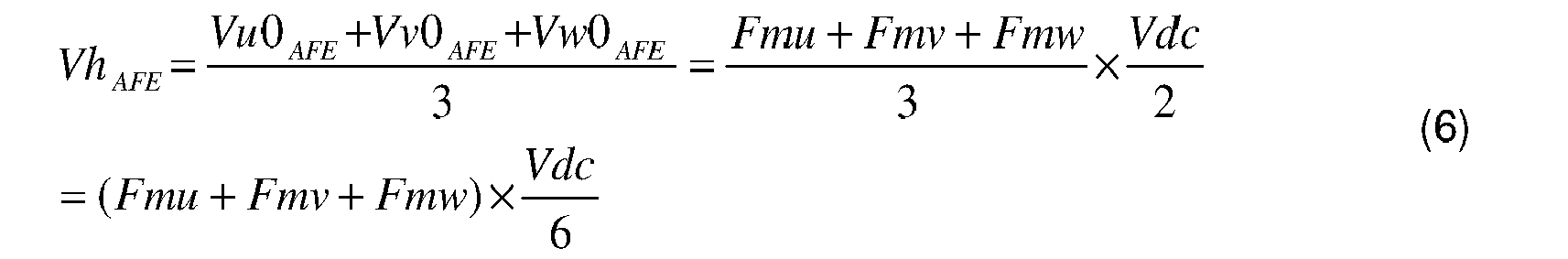
où Fmu, Fmv, Fmw représentent des fonctions de modulation de chaque phase respective U, V, W.However, the VHAFE homopolar voltage is written in the form:
where Fmu, Fmv, Fmw represent modulation functions of each respective phase U, V, W.
Dès lors, dans le cas particulier où la valeur absolue de la tension homopolaire VhAFE est inférieure ou égale à un sixième de la valeur de la tension continue Vdc, la loi de commande correspondant à la modulation de largeur d'impulsion modifiée doit alors éviter toutes les combinaisons (Fmu, Fmv, Fmw) vérifiant la condition suivante : ![]()
![]()
Les états de commutation interdits pour le redresseur 26 correspondent alors aux lignes encadrées dans le tableau ci-après :
En d'autres termes, le logiciel de modification 66 modifie la modulation de largeur d'impulsion afin d'interdire les états de commutation 0, 7, 16, 18, 20, 21, 23 et 25 par rapport à une modulation prédéterminée de largeur d'impulsion autorisant tous les états de commutation 0 à 26 dans l'exemple de réalisation du redresseur 26 à trois niveaux.In other words, the
La modification de la modulation de largeur d'impulsion est obtenue en modifiant la courbe de référence, la porteuse restant identique. La courbe de référence est modifiée de sorte que le redresseur 26 reste, en cas d'état de commutation interdit, dans l'état de commutation précédant temporellement l'état de commutation interdit selon la modulation prédéterminée de largeur d'impulsion, pendant la durée de l'état de commutation interdit telle que définie par la modulation prédéterminée de largeur d'impulsion.The modification of the pulse width modulation is obtained by modifying the reference curve, the carrier remaining identical. The reference curve is modified so that the
En variante, la courbe de référence est modifiée de sorte que le redresseur 26 passe, en cas d'état de commutation interdit, dans l'état de commutation suivant temporellement l'état de commutation interdit selon la modulation prédéterminée de largeur d'impulsion, pendant la durée de l'état de commutation interdit telle que définie par la modulation prédéterminée de largeur d'impulsion.As a variant, the reference curve is modified so that the
Sur la
Les
Sur la
Sur la
Sur la
Sans prendre en compte les surtensions dans la machine 14, la tension VuM, VvM, VwM est inférieure, en valeur absolue, à deux tiers de la valeur de la tension Vdc du bus continu 31, les seuils 125, 130 en traits pointillés représentant respectivement deux tiers de la valeur de la tension Vdc et moins deux tiers de la valeur de la tension Vdc. Dans l'exemple de réalisation de la
En prenant en compte les surtensions dans la machine 14, la tension VuM, VvM, VwM est inférieure, en valeur absolue, à 120% de la première valeur limite égale à deux tiers de la valeur de la tension Vdc, les seuils 140, 145 en traits mixtes représentant respectivement 120% de deux tiers de la valeur de la tension Vdc et 120% de moins deux tiers de la valeur de la tension Vdc. La deuxième valeur limite est égale à 120% de la première valeur limite. Les surtensions dans la machine 14 sont amorties et limitées à 20% de la valeur de tension VuM, VvM, VwM sans surtension, grâce notamment à la présence de la résistance d'amortissement 86 du dispositif de limitation.Taking into account the overvoltages in the
Ainsi, le système d'alimentation 16 selon l'invention permet de limiter la tension homopolaire, tout en ne nécessitant pas la présence d'un transformateur entre le réseau 12 et le redresseur 26, ce qui n'engendre pas de surcoûts. Ceci permet également de réduire l'encombrement mécanique du système d'alimentation 16 par rapport à un système d'alimentation avec des filtres de mode commun reliés par une liaison électrique de passage du courant de mode commun, ou encore par rapport à un système d'alimentation avec un transformateur entre le réseau et le redresseur.Thus, the
En outre, le système d'alimentation 16 selon l'invention ne comporte pas de liaison de retour entre la sortie de l'onduleur 30 et l'entrée du redresseur 26, ou entre la sortie de l'onduleur 30 et l'entrée du filtre 24. Ceci permet aussi de réduire l'encombrement mécanique du système d'alimentation 16, ainsi que son coût.In addition, the
En outre, la valeur de la tension homopolaire entre la masse électrique 22 et le neutre 18 du réseau est inférieure à 5% de la tension nominale du réseau 12 en valeur crête, de par le condensateur 36 présentant une capacité Cgh supérieure à la capacité parasite Cm de la machine électrique. Le système d'alimentation 16 ne perturbera donc pas, en termes de tension d'isolement, un autre équipement connecté directement sur le réseau électrique 12.In addition, the value of the homopolar voltage between the
Les surtensions dans la machine 14 sont amorties et limitées de par la présence de la résistance 86 du dispositif de limitation, également appelée résistance d'amortissement.The overvoltages in the
Par ailleurs, le redresseur commandé 26 permet de réduire le taux d'harmoniques sur le réseau 12 et de réguler la tension Vdc du bus continu, ainsi que le facteur de puissance de la chaine d'entrainement 10. Le redresseur commandé 26 permet également de régénérer sur le réseau 12 de l'énergie électrique issu de la machine électrique 14, en cas de freinage de cette dernière.Moreover, the controlled
La
Selon le deuxième mode de réalisation, le dispositif de limitation 34 est connecté en entrée du redresseur 26. Le dispositif de limitation 34 comporte un enroulement électromagnétique 200, pour chaque phase du courant alternatif du réseau 12, ainsi qu'un noyau 201 de couplage des enroulements magnétiques lorsque le réseau 12 est un réseau polyphasé.According to the second embodiment, the limiting
Le dispositif de limitation 34 comporte également un enroulement secondaire 202 connecté en série avec une résistance 203 d'impédance Rh, appelée résistance d'amortissement, l'enroulement secondaire 202 étant couplé magnétiquement aux enroulements primaires 200 via le noyau de couplage 201.The
En variante, la résistance d'amortissement est connectée directement en parallèle de l'enroulement électromagnétique primaire 80. En variante encore, la résistance d'amortissement est formée par la résistance équivalente aux pertes fer du noyau.As a variant, the damping resistor is connected directly in parallel with the primary electromagnetic winding 80. As a further variant, the damping resistor is formed by the resistance equivalent to the iron losses of the core.
Les bornes de sortie 44, et respectivement le point milieu de sortie 45, du redresseur sont alors directement connectées aux bornes d'entrée 70, et respectivement au point milieu d'entrée 72, de l'onduleur. Le bus continu 31 comporte deux condensateurs 204 connectés en série entre les bornes de sortie 44, ou encore entre les bornes d'entrée 70, les deux condensateurs 204 étant reliés entre eux par un point milieu 206 connecté aux points milieux 45, 72.The
Le fonctionnement de ce deuxième mode de réalisation est identique à celui du premier mode de réalisation et n'est donc pas décrit à nouveau.The operation of this second embodiment is identical to that of the first embodiment and is therefore not described again.
Les avantages de ce deuxième mode de réalisation sont identiques à ceux du premier mode de réalisation et ne sont donc pas décrits à nouveau.The advantages of this second embodiment are identical to those of the first embodiment and are therefore not described again.
La
Selon le troisième mode de réalisation, le dispositif de limitation 34 est connecté en sortie de l'onduleur 30. Le dispositif de limitation 34 comporte un enroulement électromagnétique 300, pour chaque phase du courant alternatif délivré à la machine 14, ainsi qu'un noyau 301 de couplage des enroulements magnétiques lorsque la machine électrique 14 est une machine polyphasée.According to the third embodiment, the
Le dispositif de limitation 34 comporte également un enroulement secondaire 302 connecté en série avec une résistance 303 d'impédance Rh, l'enroulement secondaire 302 étant couplé magnétiquement aux enroulements primaires 300 via le noyau de couplage 301.The
En variante, la résistance d'amortissement est connectée directement en parallèle de l'enroulement électromagnétique primaire 80. En variante encore, la résistance d'amortissement est formée par la résistance équivalente aux pertes fer du noyau.As a variant, the damping resistor is connected directly in parallel with the primary electromagnetic winding 80. As a further variant, the damping resistor is formed by the resistance equivalent to the iron losses of the core.
Les bornes de sortie 44, et respectivement le point milieu de sortie 45, du redresseur sont alors directement connectées aux bornes d'entrée 70, et respectivement au point milieu d'entrée 72, de l'onduleur. Le bus continu 31 comporte deux condensateurs 304 connectés en série entre les bornes de sortie 44, ou encore entre les bornes d'entrée 70, les deux condensateurs 304 étant reliés entre eux par un point milieu 306 connecté aux points milieux 45, 72.The
Le fonctionnement de ce troisième mode de réalisation est identique à celui du premier mode de réalisation et n'est donc pas décrit à nouveau.The operation of this third embodiment is identical to that of the first embodiment and is therefore not described again.
Les avantages de ce troisième mode de réalisation sont identiques à ceux du premier mode de réalisation et ne sont donc pas décrits à nouveau.The advantages of this third embodiment are identical to those of the first embodiment and are therefore not described again.
Claims (13)
caractérisé en ce que le dispositif de commande (28) est propre à limiter la valeur absolue de la tension (VuM, VvM, VwM) entre la masse électrique (22) et une phase (U, V, W) du courant alternatif délivré à la charge (14), en l'absence de surtensions dans la charge (14), à une première valeur limite strictement inférieure à celle de la tension (Vdc) du bus continu (31).
characterized in that the control device (28) is adapted to limit the absolute value of the voltage (VuM, VvM, VwM) between the electrical mass (22) and a phase (U, V, W) of the alternating current delivered to the load (14), in the absence of overvoltages in the load (14), at a first limit value strictly lower than that of the voltage (Vdc) of the DC bus (31).
Applications Claiming Priority (1)
| Application Number | Priority Date | Filing Date | Title |
|---|---|---|---|
| FR1056278A FR2963509B1 (en) | 2010-07-29 | 2010-07-29 | SYSTEM FOR SUPPLYING AN ALTERNATING CURRENT CHARGE FROM AN ALTERNATIVE NETWORK WITHOUT A TRANSFORMER BETWEEN THE NETWORK AND THE POWER SUPPLY SYSTEM, AND A DRIVE CHAIN COMPRISING SUCH A SYSTEM |
Publications (2)
| Publication Number | Publication Date |
|---|---|
| EP2413485A1 true EP2413485A1 (en) | 2012-02-01 |
| EP2413485B1 EP2413485B1 (en) | 2015-01-07 |
Family
ID=43446341
Family Applications (1)
| Application Number | Title | Priority Date | Filing Date |
|---|---|---|---|
| EP11305988.5A Active EP2413485B1 (en) | 2010-07-29 | 2011-07-28 | System for supplying an alternating current charge from an AC grid with no transformer between the grid and the supply system, and power transmission chain including such a system |
Country Status (2)
| Country | Link |
|---|---|
| EP (1) | EP2413485B1 (en) |
| FR (1) | FR2963509B1 (en) |
Cited By (4)
| Publication number | Priority date | Publication date | Assignee | Title |
|---|---|---|---|---|
| CN103516226A (en) * | 2012-06-19 | 2014-01-15 | Ge能源电力转换技术有限公司 | Power supply system and drive chain comprising such a power supply system |
| CN104967332A (en) * | 2015-06-30 | 2015-10-07 | 南车株洲电力机车研究所有限公司 | Method and device for realizing multifunctional current transformer module |
| EP3148032A1 (en) | 2015-09-28 | 2017-03-29 | GE Energy Power Conversion Technology Ltd | Power supply system of a set of loads connected in parallel to a dc power bus |
| EP3255774A1 (en) | 2016-06-07 | 2017-12-13 | GE Energy Power Conversion Technology Ltd | System for converting electric energy supplied by a network and conversion method implemented by means of such a conversion system |
Families Citing this family (1)
| Publication number | Priority date | Publication date | Assignee | Title |
|---|---|---|---|---|
| CN110667418B (en) * | 2019-09-17 | 2021-02-05 | 华中科技大学 | Single-phase grid-connected zero-torque integrated charger and current control method thereof |
Citations (5)
| Publication number | Priority date | Publication date | Assignee | Title |
|---|---|---|---|---|
| EP1641111A2 (en) * | 2004-09-28 | 2006-03-29 | Rockwell Automation Technologies, Inc. | Method and apparatus to reduce common mode voltages applied to a load by a drive |
| US20070211501A1 (en) | 2006-03-01 | 2007-09-13 | Rockwell Automation Technologies, Inc. | Power converter with reduced common mode voltage |
| WO2008024410A2 (en) * | 2006-08-22 | 2008-02-28 | Regents Of The University Of Minnesota | Open-ended control circuit for electrical apparatus |
| EP2157683A2 (en) * | 2008-08-20 | 2010-02-24 | Hamilton Sundstrand Corporation | Power conversion architecture with zero common mode voltage |
| EP2202875A1 (en) * | 2008-12-24 | 2010-06-30 | Converteam Technology Ltd | System for converting at least one direct-current electric input to a multi-phase alternating-current electric output |
-
2010
- 2010-07-29 FR FR1056278A patent/FR2963509B1/en active Active
-
2011
- 2011-07-28 EP EP11305988.5A patent/EP2413485B1/en active Active
Patent Citations (5)
| Publication number | Priority date | Publication date | Assignee | Title |
|---|---|---|---|---|
| EP1641111A2 (en) * | 2004-09-28 | 2006-03-29 | Rockwell Automation Technologies, Inc. | Method and apparatus to reduce common mode voltages applied to a load by a drive |
| US20070211501A1 (en) | 2006-03-01 | 2007-09-13 | Rockwell Automation Technologies, Inc. | Power converter with reduced common mode voltage |
| WO2008024410A2 (en) * | 2006-08-22 | 2008-02-28 | Regents Of The University Of Minnesota | Open-ended control circuit for electrical apparatus |
| EP2157683A2 (en) * | 2008-08-20 | 2010-02-24 | Hamilton Sundstrand Corporation | Power conversion architecture with zero common mode voltage |
| EP2202875A1 (en) * | 2008-12-24 | 2010-06-30 | Converteam Technology Ltd | System for converting at least one direct-current electric input to a multi-phase alternating-current electric output |
Cited By (7)
| Publication number | Priority date | Publication date | Assignee | Title |
|---|---|---|---|---|
| CN103516226A (en) * | 2012-06-19 | 2014-01-15 | Ge能源电力转换技术有限公司 | Power supply system and drive chain comprising such a power supply system |
| CN103516226B (en) * | 2012-06-19 | 2017-04-12 | Ge能源电力转换技术有限公司 | Power supply system and drive chain comprising such a power supply system |
| CN104967332A (en) * | 2015-06-30 | 2015-10-07 | 南车株洲电力机车研究所有限公司 | Method and device for realizing multifunctional current transformer module |
| EP3148032A1 (en) | 2015-09-28 | 2017-03-29 | GE Energy Power Conversion Technology Ltd | Power supply system of a set of loads connected in parallel to a dc power bus |
| WO2017055817A1 (en) | 2015-09-28 | 2017-04-06 | Ge Energy Power Conversion Technology Limited | Supply system for a plurality of loads connected in parallel to a direct current supply bus |
| US10972000B2 (en) | 2015-09-28 | 2021-04-06 | Ge Energy Power Conversion Technology, Ltd. | Supply system to a set of loads connected in parallel to a direct current supply bus |
| EP3255774A1 (en) | 2016-06-07 | 2017-12-13 | GE Energy Power Conversion Technology Ltd | System for converting electric energy supplied by a network and conversion method implemented by means of such a conversion system |
Also Published As
| Publication number | Publication date |
|---|---|
| FR2963509B1 (en) | 2013-07-26 |
| FR2963509A1 (en) | 2012-02-03 |
| EP2413485B1 (en) | 2015-01-07 |
Similar Documents
| Publication | Publication Date | Title |
|---|---|---|
| EP2413485B1 (en) | System for supplying an alternating current charge from an AC grid with no transformer between the grid and the supply system, and power transmission chain including such a system | |
| EP3045343B1 (en) | A convertor for electric feeder and/or substation for recuperating the braking energy | |
| EP3053236B1 (en) | Method of discharging at least one electrical energy storage unit, in particular a capacitor, of an electrical circuit | |
| EP2048771A1 (en) | EMC filtering device in a variable speed drive | |
| EP2677645B1 (en) | System for powering a load, comprising a converter connected to a network and a transformer connected in parallel to the converter to limit the zero sequence current, and drive chain comprising such a system | |
| EP2660095B1 (en) | Converter stage, electrical converter comprising such a converter stage, ac/dc converter comprising such a converter, and battery charching terminal comprising such a converter or converter stage | |
| EP1580873B1 (en) | Apparatus and method for control of a converter and converter and electrical installation comprising such an apparatus | |
| FR2999357A1 (en) | ELECTRIC DRIVE CHAIN OF A DEVICE, AND GAS COMPRESSION EQUIPMENT COMPRISING SUCH A CHAIN | |
| EP2562903A2 (en) | Reactive power compensator comprising N inverters in parallel, N banks of capacitor(s) and a means for connecting the banks via passive electrical components | |
| EP2822800B1 (en) | Method for discharging at least one capacitor of an electric circuit | |
| FR2923331B1 (en) | ROTARY ELECTRICAL APPARATUS FOR AUTOMOBILE | |
| EP3171505B1 (en) | Device for charging a traction battery of a motor vehicle with at least partially electric traction | |
| EP3148032B1 (en) | Power supply system of a set of loads connected in parallel to a dc power bus | |
| EP2751916B1 (en) | High-power converter including low-power transistors connected in parallel | |
| EP2346154A1 (en) | System for powering an element among a rotor and a stator of an electric machine, and method for controlling such a system | |
| EP2571149B1 (en) | Method and circuit arrangement for reducing common mode current | |
| EP2638632B1 (en) | Power supply circuit for an aircraft including an asynchronous machine | |
| EP3476034B1 (en) | System and method for converting dc power into three-phase ac power, the system comprising filtering means | |
| FR2668664A1 (en) | CUT-OUT VOLTAGE CONVERTER WITH IMPROVED CONTROL. | |
| FR2998115A1 (en) | Electric conversion stage for electric converter of electric battery recharging terminal of car, has capacitor connected between output terminals, and electromagnetic coil connected between one of terminals and midpoint of switching branch | |
| EP2647112B1 (en) | Variable speed drive provided with a common-mode filtering device | |
| WO2012084389A2 (en) | Power converter equipped at the output with a filtering device | |
| FR2990310A1 (en) | Electric conversion stage for electric converter of electric battery recharging terminal of car, has capacitor connected between output terminals, and electromagnetic coil connected between one of terminals and midpoint of switching branch | |
| EP2249477A1 (en) | Power supply system for electric motors containing passive filter with coupled coils | |
| EP2293422B1 (en) | Converter of one direct current to another direct current with control signal interleaving, and power supply system including such a converter |
Legal Events
| Date | Code | Title | Description |
|---|---|---|---|
| AK | Designated contracting states |
Kind code of ref document: A1 Designated state(s): AL AT BE BG CH CY CZ DE DK EE ES FI FR GB GR HR HU IE IS IT LI LT LU LV MC MK MT NL NO PL PT RO RS SE SI SK SM TR |
|
| AX | Request for extension of the european patent |
Extension state: BA ME |
|
| PUAI | Public reference made under article 153(3) epc to a published international application that has entered the european phase |
Free format text: ORIGINAL CODE: 0009012 |
|
| 17P | Request for examination filed |
Effective date: 20120702 |
|
| RAP1 | Party data changed (applicant data changed or rights of an application transferred) |
Owner name: GE ENERGY POWER CONVERSION TECHNOLOGY LIMITED |
|
| RIC1 | Information provided on ipc code assigned before grant |
Ipc: H02M 7/5387 20070101ALI20140626BHEP Ipc: H02M 5/458 20060101AFI20140626BHEP Ipc: H02M 1/12 20060101ALI20140626BHEP |
|
| GRAP | Despatch of communication of intention to grant a patent |
Free format text: ORIGINAL CODE: EPIDOSNIGR1 |
|
| INTG | Intention to grant announced |
Effective date: 20140805 |
|
| GRAS | Grant fee paid |
Free format text: ORIGINAL CODE: EPIDOSNIGR3 |
|
| GRAA | (expected) grant |
Free format text: ORIGINAL CODE: 0009210 |
|
| AK | Designated contracting states |
Kind code of ref document: B1 Designated state(s): AL AT BE BG CH CY CZ DE DK EE ES FI FR GB GR HR HU IE IS IT LI LT LU LV MC MK MT NL NO PL PT RO RS SE SI SK SM TR |
|
| REG | Reference to a national code |
Ref country code: GB Ref legal event code: FG4D Free format text: NOT ENGLISH |
|
| REG | Reference to a national code |
Ref country code: CH Ref legal event code: EP |
|
| REG | Reference to a national code |
Ref country code: IE Ref legal event code: FG4D Free format text: LANGUAGE OF EP DOCUMENT: FRENCH |
|
| REG | Reference to a national code |
Ref country code: AT Ref legal event code: REF Ref document number: 706328 Country of ref document: AT Kind code of ref document: T Effective date: 20150215 |
|
| REG | Reference to a national code |
Ref country code: DE Ref legal event code: R096 Ref document number: 602011012856 Country of ref document: DE Effective date: 20150219 |
|
| REG | Reference to a national code |
Ref country code: NL Ref legal event code: VDEP Effective date: 20150107 |
|
| REG | Reference to a national code |
Ref country code: AT Ref legal event code: MK05 Ref document number: 706328 Country of ref document: AT Kind code of ref document: T Effective date: 20150107 |
|
| REG | Reference to a national code |
Ref country code: LT Ref legal event code: MG4D |
|
| PG25 | Lapsed in a contracting state [announced via postgrant information from national office to epo] |
Ref country code: SE Free format text: LAPSE BECAUSE OF FAILURE TO SUBMIT A TRANSLATION OF THE DESCRIPTION OR TO PAY THE FEE WITHIN THE PRESCRIBED TIME-LIMIT Effective date: 20150107 Ref country code: NO Free format text: LAPSE BECAUSE OF FAILURE TO SUBMIT A TRANSLATION OF THE DESCRIPTION OR TO PAY THE FEE WITHIN THE PRESCRIBED TIME-LIMIT Effective date: 20150407 Ref country code: ES Free format text: LAPSE BECAUSE OF FAILURE TO SUBMIT A TRANSLATION OF THE DESCRIPTION OR TO PAY THE FEE WITHIN THE PRESCRIBED TIME-LIMIT Effective date: 20150107 Ref country code: LT Free format text: LAPSE BECAUSE OF FAILURE TO SUBMIT A TRANSLATION OF THE DESCRIPTION OR TO PAY THE FEE WITHIN THE PRESCRIBED TIME-LIMIT Effective date: 20150107 Ref country code: BG Free format text: LAPSE BECAUSE OF FAILURE TO SUBMIT A TRANSLATION OF THE DESCRIPTION OR TO PAY THE FEE WITHIN THE PRESCRIBED TIME-LIMIT Effective date: 20150407 Ref country code: HR Free format text: LAPSE BECAUSE OF FAILURE TO SUBMIT A TRANSLATION OF THE DESCRIPTION OR TO PAY THE FEE WITHIN THE PRESCRIBED TIME-LIMIT Effective date: 20150107 Ref country code: FI Free format text: LAPSE BECAUSE OF FAILURE TO SUBMIT A TRANSLATION OF THE DESCRIPTION OR TO PAY THE FEE WITHIN THE PRESCRIBED TIME-LIMIT Effective date: 20150107 |
|
| PG25 | Lapsed in a contracting state [announced via postgrant information from national office to epo] |
Ref country code: AT Free format text: LAPSE BECAUSE OF FAILURE TO SUBMIT A TRANSLATION OF THE DESCRIPTION OR TO PAY THE FEE WITHIN THE PRESCRIBED TIME-LIMIT Effective date: 20150107 Ref country code: NL Free format text: LAPSE BECAUSE OF FAILURE TO SUBMIT A TRANSLATION OF THE DESCRIPTION OR TO PAY THE FEE WITHIN THE PRESCRIBED TIME-LIMIT Effective date: 20150107 Ref country code: PL Free format text: LAPSE BECAUSE OF FAILURE TO SUBMIT A TRANSLATION OF THE DESCRIPTION OR TO PAY THE FEE WITHIN THE PRESCRIBED TIME-LIMIT Effective date: 20150107 Ref country code: RS Free format text: LAPSE BECAUSE OF FAILURE TO SUBMIT A TRANSLATION OF THE DESCRIPTION OR TO PAY THE FEE WITHIN THE PRESCRIBED TIME-LIMIT Effective date: 20150107 Ref country code: IS Free format text: LAPSE BECAUSE OF FAILURE TO SUBMIT A TRANSLATION OF THE DESCRIPTION OR TO PAY THE FEE WITHIN THE PRESCRIBED TIME-LIMIT Effective date: 20150507 Ref country code: LV Free format text: LAPSE BECAUSE OF FAILURE TO SUBMIT A TRANSLATION OF THE DESCRIPTION OR TO PAY THE FEE WITHIN THE PRESCRIBED TIME-LIMIT Effective date: 20150107 Ref country code: GR Free format text: LAPSE BECAUSE OF FAILURE TO SUBMIT A TRANSLATION OF THE DESCRIPTION OR TO PAY THE FEE WITHIN THE PRESCRIBED TIME-LIMIT Effective date: 20150408 |
|
| REG | Reference to a national code |
Ref country code: DE Ref legal event code: R097 Ref document number: 602011012856 Country of ref document: DE |
|
| PG25 | Lapsed in a contracting state [announced via postgrant information from national office to epo] |
Ref country code: RO Free format text: LAPSE BECAUSE OF FAILURE TO SUBMIT A TRANSLATION OF THE DESCRIPTION OR TO PAY THE FEE WITHIN THE PRESCRIBED TIME-LIMIT Effective date: 20150107 Ref country code: SK Free format text: LAPSE BECAUSE OF FAILURE TO SUBMIT A TRANSLATION OF THE DESCRIPTION OR TO PAY THE FEE WITHIN THE PRESCRIBED TIME-LIMIT Effective date: 20150107 Ref country code: EE Free format text: LAPSE BECAUSE OF FAILURE TO SUBMIT A TRANSLATION OF THE DESCRIPTION OR TO PAY THE FEE WITHIN THE PRESCRIBED TIME-LIMIT Effective date: 20150107 Ref country code: CZ Free format text: LAPSE BECAUSE OF FAILURE TO SUBMIT A TRANSLATION OF THE DESCRIPTION OR TO PAY THE FEE WITHIN THE PRESCRIBED TIME-LIMIT Effective date: 20150107 Ref country code: DK Free format text: LAPSE BECAUSE OF FAILURE TO SUBMIT A TRANSLATION OF THE DESCRIPTION OR TO PAY THE FEE WITHIN THE PRESCRIBED TIME-LIMIT Effective date: 20150107 |
|
| PLBE | No opposition filed within time limit |
Free format text: ORIGINAL CODE: 0009261 |
|
| STAA | Information on the status of an ep patent application or granted ep patent |
Free format text: STATUS: NO OPPOSITION FILED WITHIN TIME LIMIT |
|
| 26N | No opposition filed |
Effective date: 20151008 |
|
| PG25 | Lapsed in a contracting state [announced via postgrant information from national office to epo] |
Ref country code: IT Free format text: LAPSE BECAUSE OF FAILURE TO SUBMIT A TRANSLATION OF THE DESCRIPTION OR TO PAY THE FEE WITHIN THE PRESCRIBED TIME-LIMIT Effective date: 20150107 |
|
| PG25 | Lapsed in a contracting state [announced via postgrant information from national office to epo] |
Ref country code: MC Free format text: LAPSE BECAUSE OF FAILURE TO SUBMIT A TRANSLATION OF THE DESCRIPTION OR TO PAY THE FEE WITHIN THE PRESCRIBED TIME-LIMIT Effective date: 20150107 Ref country code: SI Free format text: LAPSE BECAUSE OF FAILURE TO SUBMIT A TRANSLATION OF THE DESCRIPTION OR TO PAY THE FEE WITHIN THE PRESCRIBED TIME-LIMIT Effective date: 20150107 |
|
| REG | Reference to a national code |
Ref country code: CH Ref legal event code: PL |
|
| PG25 | Lapsed in a contracting state [announced via postgrant information from national office to epo] |
Ref country code: LU Free format text: LAPSE BECAUSE OF FAILURE TO SUBMIT A TRANSLATION OF THE DESCRIPTION OR TO PAY THE FEE WITHIN THE PRESCRIBED TIME-LIMIT Effective date: 20150728 |
|
| REG | Reference to a national code |
Ref country code: IE Ref legal event code: MM4A |
|
| PG25 | Lapsed in a contracting state [announced via postgrant information from national office to epo] |
Ref country code: CH Free format text: LAPSE BECAUSE OF NON-PAYMENT OF DUE FEES Effective date: 20150731 Ref country code: LI Free format text: LAPSE BECAUSE OF NON-PAYMENT OF DUE FEES Effective date: 20150731 |
|
| REG | Reference to a national code |
Ref country code: FR Ref legal event code: PLFP Year of fee payment: 6 |
|
| PG25 | Lapsed in a contracting state [announced via postgrant information from national office to epo] |
Ref country code: IE Free format text: LAPSE BECAUSE OF NON-PAYMENT OF DUE FEES Effective date: 20150728 |
|
| PG25 | Lapsed in a contracting state [announced via postgrant information from national office to epo] |
Ref country code: MT Free format text: LAPSE BECAUSE OF FAILURE TO SUBMIT A TRANSLATION OF THE DESCRIPTION OR TO PAY THE FEE WITHIN THE PRESCRIBED TIME-LIMIT Effective date: 20150107 |
|
| PG25 | Lapsed in a contracting state [announced via postgrant information from national office to epo] |
Ref country code: SM Free format text: LAPSE BECAUSE OF FAILURE TO SUBMIT A TRANSLATION OF THE DESCRIPTION OR TO PAY THE FEE WITHIN THE PRESCRIBED TIME-LIMIT Effective date: 20150107 Ref country code: HU Free format text: LAPSE BECAUSE OF FAILURE TO SUBMIT A TRANSLATION OF THE DESCRIPTION OR TO PAY THE FEE WITHIN THE PRESCRIBED TIME-LIMIT; INVALID AB INITIO Effective date: 20110728 |
|
| PG25 | Lapsed in a contracting state [announced via postgrant information from national office to epo] |
Ref country code: CY Free format text: LAPSE BECAUSE OF FAILURE TO SUBMIT A TRANSLATION OF THE DESCRIPTION OR TO PAY THE FEE WITHIN THE PRESCRIBED TIME-LIMIT Effective date: 20150107 |
|
| REG | Reference to a national code |
Ref country code: FR Ref legal event code: PLFP Year of fee payment: 7 |
|
| PG25 | Lapsed in a contracting state [announced via postgrant information from national office to epo] |
Ref country code: BE Free format text: LAPSE BECAUSE OF NON-PAYMENT OF DUE FEES Effective date: 20150731 |
|
| PG25 | Lapsed in a contracting state [announced via postgrant information from national office to epo] |
Ref country code: TR Free format text: LAPSE BECAUSE OF FAILURE TO SUBMIT A TRANSLATION OF THE DESCRIPTION OR TO PAY THE FEE WITHIN THE PRESCRIBED TIME-LIMIT Effective date: 20150107 |
|
| REG | Reference to a national code |
Ref country code: FR Ref legal event code: PLFP Year of fee payment: 8 |
|
| PG25 | Lapsed in a contracting state [announced via postgrant information from national office to epo] |
Ref country code: MK Free format text: LAPSE BECAUSE OF FAILURE TO SUBMIT A TRANSLATION OF THE DESCRIPTION OR TO PAY THE FEE WITHIN THE PRESCRIBED TIME-LIMIT Effective date: 20150107 Ref country code: PT Free format text: LAPSE BECAUSE OF FAILURE TO SUBMIT A TRANSLATION OF THE DESCRIPTION OR TO PAY THE FEE WITHIN THE PRESCRIBED TIME-LIMIT Effective date: 20150107 |
|
| PG25 | Lapsed in a contracting state [announced via postgrant information from national office to epo] |
Ref country code: AL Free format text: LAPSE BECAUSE OF FAILURE TO SUBMIT A TRANSLATION OF THE DESCRIPTION OR TO PAY THE FEE WITHIN THE PRESCRIBED TIME-LIMIT Effective date: 20150107 |
|
| PGFP | Annual fee paid to national office [announced via postgrant information from national office to epo] |
Ref country code: FR Payment date: 20230621 Year of fee payment: 13 |
|
| PGFP | Annual fee paid to national office [announced via postgrant information from national office to epo] |
Ref country code: GB Payment date: 20230620 Year of fee payment: 13 |
|
| PGFP | Annual fee paid to national office [announced via postgrant information from national office to epo] |
Ref country code: DE Payment date: 20230620 Year of fee payment: 13 |