EP2325971A2 - Multi-tasking power processor for a vehicle electric system - Google Patents
Multi-tasking power processor for a vehicle electric system Download PDFInfo
- Publication number
- EP2325971A2 EP2325971A2 EP10251980A EP10251980A EP2325971A2 EP 2325971 A2 EP2325971 A2 EP 2325971A2 EP 10251980 A EP10251980 A EP 10251980A EP 10251980 A EP10251980 A EP 10251980A EP 2325971 A2 EP2325971 A2 EP 2325971A2
- Authority
- EP
- European Patent Office
- Prior art keywords
- direct current
- voltage direct
- current bus
- motor
- contactors
- Prior art date
- Legal status (The legal status is an assumption and is not a legal conclusion. Google has not performed a legal analysis and makes no representation as to the accuracy of the status listed.)
- Granted
Links
- 238000004146 energy storage Methods 0.000 claims description 15
- 238000000034 method Methods 0.000 claims description 11
- 238000001816 cooling Methods 0.000 claims description 6
- 230000008878 coupling Effects 0.000 claims description 3
- 238000010168 coupling process Methods 0.000 claims description 3
- 238000005859 coupling reaction Methods 0.000 claims description 3
- 238000012544 monitoring process Methods 0.000 claims 1
- 238000006243 chemical reaction Methods 0.000 description 10
- 239000007858 starting material Substances 0.000 description 4
- 230000001133 acceleration Effects 0.000 description 3
- 230000001360 synchronised effect Effects 0.000 description 3
- 230000001052 transient effect Effects 0.000 description 2
- 230000004075 alteration Effects 0.000 description 1
- 230000000740 bleeding effect Effects 0.000 description 1
- 239000003990 capacitor Substances 0.000 description 1
- 230000007613 environmental effect Effects 0.000 description 1
- 230000001172 regenerating effect Effects 0.000 description 1
- 238000006467 substitution reaction Methods 0.000 description 1
Images

Classifications
-
- H—ELECTRICITY
- H02—GENERATION; CONVERSION OR DISTRIBUTION OF ELECTRIC POWER
- H02J—CIRCUIT ARRANGEMENTS OR SYSTEMS FOR SUPPLYING OR DISTRIBUTING ELECTRIC POWER; SYSTEMS FOR STORING ELECTRIC ENERGY
- H02J3/00—Circuit arrangements for ac mains or ac distribution networks
- H02J3/38—Arrangements for parallely feeding a single network by two or more generators, converters or transformers
-
- B—PERFORMING OPERATIONS; TRANSPORTING
- B60—VEHICLES IN GENERAL
- B60L—PROPULSION OF ELECTRICALLY-PROPELLED VEHICLES; SUPPLYING ELECTRIC POWER FOR AUXILIARY EQUIPMENT OF ELECTRICALLY-PROPELLED VEHICLES; ELECTRODYNAMIC BRAKE SYSTEMS FOR VEHICLES IN GENERAL; MAGNETIC SUSPENSION OR LEVITATION FOR VEHICLES; MONITORING OPERATING VARIABLES OF ELECTRICALLY-PROPELLED VEHICLES; ELECTRIC SAFETY DEVICES FOR ELECTRICALLY-PROPELLED VEHICLES
- B60L53/00—Methods of charging batteries, specially adapted for electric vehicles; Charging stations or on-board charging equipment therefor; Exchange of energy storage elements in electric vehicles
- B60L53/20—Methods of charging batteries, specially adapted for electric vehicles; Charging stations or on-board charging equipment therefor; Exchange of energy storage elements in electric vehicles characterised by converters located in the vehicle
-
- H—ELECTRICITY
- H02—GENERATION; CONVERSION OR DISTRIBUTION OF ELECTRIC POWER
- H02P—CONTROL OR REGULATION OF ELECTRIC MOTORS, ELECTRIC GENERATORS OR DYNAMO-ELECTRIC CONVERTERS; CONTROLLING TRANSFORMERS, REACTORS OR CHOKE COILS
- H02P27/00—Arrangements or methods for the control of AC motors characterised by the kind of supply voltage
- H02P27/04—Arrangements or methods for the control of AC motors characterised by the kind of supply voltage using variable-frequency supply voltage, e.g. inverter or converter supply voltage
- H02P27/06—Arrangements or methods for the control of AC motors characterised by the kind of supply voltage using variable-frequency supply voltage, e.g. inverter or converter supply voltage using dc to ac converters or inverters
-
- B—PERFORMING OPERATIONS; TRANSPORTING
- B60—VEHICLES IN GENERAL
- B60L—PROPULSION OF ELECTRICALLY-PROPELLED VEHICLES; SUPPLYING ELECTRIC POWER FOR AUXILIARY EQUIPMENT OF ELECTRICALLY-PROPELLED VEHICLES; ELECTRODYNAMIC BRAKE SYSTEMS FOR VEHICLES IN GENERAL; MAGNETIC SUSPENSION OR LEVITATION FOR VEHICLES; MONITORING OPERATING VARIABLES OF ELECTRICALLY-PROPELLED VEHICLES; ELECTRIC SAFETY DEVICES FOR ELECTRICALLY-PROPELLED VEHICLES
- B60L2210/00—Converter types
- B60L2210/10—DC to DC converters
- B60L2210/12—Buck converters
-
- B—PERFORMING OPERATIONS; TRANSPORTING
- B60—VEHICLES IN GENERAL
- B60L—PROPULSION OF ELECTRICALLY-PROPELLED VEHICLES; SUPPLYING ELECTRIC POWER FOR AUXILIARY EQUIPMENT OF ELECTRICALLY-PROPELLED VEHICLES; ELECTRODYNAMIC BRAKE SYSTEMS FOR VEHICLES IN GENERAL; MAGNETIC SUSPENSION OR LEVITATION FOR VEHICLES; MONITORING OPERATING VARIABLES OF ELECTRICALLY-PROPELLED VEHICLES; ELECTRIC SAFETY DEVICES FOR ELECTRICALLY-PROPELLED VEHICLES
- B60L2210/00—Converter types
- B60L2210/10—DC to DC converters
- B60L2210/14—Boost converters
-
- H—ELECTRICITY
- H02—GENERATION; CONVERSION OR DISTRIBUTION OF ELECTRIC POWER
- H02J—CIRCUIT ARRANGEMENTS OR SYSTEMS FOR SUPPLYING OR DISTRIBUTING ELECTRIC POWER; SYSTEMS FOR STORING ELECTRIC ENERGY
- H02J2310/00—The network for supplying or distributing electric power characterised by its spatial reach or by the load
- H02J2310/40—The network being an on-board power network, i.e. within a vehicle
- H02J2310/48—The network being an on-board power network, i.e. within a vehicle for electric vehicles [EV] or hybrid vehicles [HEV]
-
- Y—GENERAL TAGGING OF NEW TECHNOLOGICAL DEVELOPMENTS; GENERAL TAGGING OF CROSS-SECTIONAL TECHNOLOGIES SPANNING OVER SEVERAL SECTIONS OF THE IPC; TECHNICAL SUBJECTS COVERED BY FORMER USPC CROSS-REFERENCE ART COLLECTIONS [XRACs] AND DIGESTS
- Y02—TECHNOLOGIES OR APPLICATIONS FOR MITIGATION OR ADAPTATION AGAINST CLIMATE CHANGE
- Y02E—REDUCTION OF GREENHOUSE GAS [GHG] EMISSIONS, RELATED TO ENERGY GENERATION, TRANSMISSION OR DISTRIBUTION
- Y02E60/00—Enabling technologies; Technologies with a potential or indirect contribution to GHG emissions mitigation
-
- Y—GENERAL TAGGING OF NEW TECHNOLOGICAL DEVELOPMENTS; GENERAL TAGGING OF CROSS-SECTIONAL TECHNOLOGIES SPANNING OVER SEVERAL SECTIONS OF THE IPC; TECHNICAL SUBJECTS COVERED BY FORMER USPC CROSS-REFERENCE ART COLLECTIONS [XRACs] AND DIGESTS
- Y02—TECHNOLOGIES OR APPLICATIONS FOR MITIGATION OR ADAPTATION AGAINST CLIMATE CHANGE
- Y02T—CLIMATE CHANGE MITIGATION TECHNOLOGIES RELATED TO TRANSPORTATION
- Y02T10/00—Road transport of goods or passengers
- Y02T10/60—Other road transportation technologies with climate change mitigation effect
- Y02T10/64—Electric machine technologies in electromobility
-
- Y—GENERAL TAGGING OF NEW TECHNOLOGICAL DEVELOPMENTS; GENERAL TAGGING OF CROSS-SECTIONAL TECHNOLOGIES SPANNING OVER SEVERAL SECTIONS OF THE IPC; TECHNICAL SUBJECTS COVERED BY FORMER USPC CROSS-REFERENCE ART COLLECTIONS [XRACs] AND DIGESTS
- Y02—TECHNOLOGIES OR APPLICATIONS FOR MITIGATION OR ADAPTATION AGAINST CLIMATE CHANGE
- Y02T—CLIMATE CHANGE MITIGATION TECHNOLOGIES RELATED TO TRANSPORTATION
- Y02T10/00—Road transport of goods or passengers
- Y02T10/60—Other road transportation technologies with climate change mitigation effect
- Y02T10/70—Energy storage systems for electromobility, e.g. batteries
-
- Y—GENERAL TAGGING OF NEW TECHNOLOGICAL DEVELOPMENTS; GENERAL TAGGING OF CROSS-SECTIONAL TECHNOLOGIES SPANNING OVER SEVERAL SECTIONS OF THE IPC; TECHNICAL SUBJECTS COVERED BY FORMER USPC CROSS-REFERENCE ART COLLECTIONS [XRACs] AND DIGESTS
- Y02—TECHNOLOGIES OR APPLICATIONS FOR MITIGATION OR ADAPTATION AGAINST CLIMATE CHANGE
- Y02T—CLIMATE CHANGE MITIGATION TECHNOLOGIES RELATED TO TRANSPORTATION
- Y02T10/00—Road transport of goods or passengers
- Y02T10/60—Other road transportation technologies with climate change mitigation effect
- Y02T10/7072—Electromobility specific charging systems or methods for batteries, ultracapacitors, supercapacitors or double-layer capacitors
-
- Y—GENERAL TAGGING OF NEW TECHNOLOGICAL DEVELOPMENTS; GENERAL TAGGING OF CROSS-SECTIONAL TECHNOLOGIES SPANNING OVER SEVERAL SECTIONS OF THE IPC; TECHNICAL SUBJECTS COVERED BY FORMER USPC CROSS-REFERENCE ART COLLECTIONS [XRACs] AND DIGESTS
- Y02—TECHNOLOGIES OR APPLICATIONS FOR MITIGATION OR ADAPTATION AGAINST CLIMATE CHANGE
- Y02T—CLIMATE CHANGE MITIGATION TECHNOLOGIES RELATED TO TRANSPORTATION
- Y02T10/00—Road transport of goods or passengers
- Y02T10/60—Other road transportation technologies with climate change mitigation effect
- Y02T10/72—Electric energy management in electromobility
-
- Y—GENERAL TAGGING OF NEW TECHNOLOGICAL DEVELOPMENTS; GENERAL TAGGING OF CROSS-SECTIONAL TECHNOLOGIES SPANNING OVER SEVERAL SECTIONS OF THE IPC; TECHNICAL SUBJECTS COVERED BY FORMER USPC CROSS-REFERENCE ART COLLECTIONS [XRACs] AND DIGESTS
- Y02—TECHNOLOGIES OR APPLICATIONS FOR MITIGATION OR ADAPTATION AGAINST CLIMATE CHANGE
- Y02T—CLIMATE CHANGE MITIGATION TECHNOLOGIES RELATED TO TRANSPORTATION
- Y02T90/00—Enabling technologies or technologies with a potential or indirect contribution to GHG emissions mitigation
- Y02T90/10—Technologies relating to charging of electric vehicles
- Y02T90/12—Electric charging stations
-
- Y—GENERAL TAGGING OF NEW TECHNOLOGICAL DEVELOPMENTS; GENERAL TAGGING OF CROSS-SECTIONAL TECHNOLOGIES SPANNING OVER SEVERAL SECTIONS OF THE IPC; TECHNICAL SUBJECTS COVERED BY FORMER USPC CROSS-REFERENCE ART COLLECTIONS [XRACs] AND DIGESTS
- Y02—TECHNOLOGIES OR APPLICATIONS FOR MITIGATION OR ADAPTATION AGAINST CLIMATE CHANGE
- Y02T—CLIMATE CHANGE MITIGATION TECHNOLOGIES RELATED TO TRANSPORTATION
- Y02T90/00—Enabling technologies or technologies with a potential or indirect contribution to GHG emissions mitigation
- Y02T90/10—Technologies relating to charging of electric vehicles
- Y02T90/14—Plug-in electric vehicles
-
- Y—GENERAL TAGGING OF NEW TECHNOLOGICAL DEVELOPMENTS; GENERAL TAGGING OF CROSS-SECTIONAL TECHNOLOGIES SPANNING OVER SEVERAL SECTIONS OF THE IPC; TECHNICAL SUBJECTS COVERED BY FORMER USPC CROSS-REFERENCE ART COLLECTIONS [XRACs] AND DIGESTS
- Y04—INFORMATION OR COMMUNICATION TECHNOLOGIES HAVING AN IMPACT ON OTHER TECHNOLOGY AREAS
- Y04S—SYSTEMS INTEGRATING TECHNOLOGIES RELATED TO POWER NETWORK OPERATION, COMMUNICATION OR INFORMATION TECHNOLOGIES FOR IMPROVING THE ELECTRICAL POWER GENERATION, TRANSMISSION, DISTRIBUTION, MANAGEMENT OR USAGE, i.e. SMART GRIDS
- Y04S10/00—Systems supporting electrical power generation, transmission or distribution
- Y04S10/12—Monitoring or controlling equipment for energy generation units, e.g. distributed energy generation [DER] or load-side generation
- Y04S10/126—Monitoring or controlling equipment for energy generation units, e.g. distributed energy generation [DER] or load-side generation the energy generation units being or involving electric vehicles [EV] or hybrid vehicles [HEV], i.e. power aggregation of EV or HEV, vehicle to grid arrangements [V2G]
Definitions
- the subject matter disclosed herein generally relates to electrical power distribution, and more particularly to a multi-tasking power processor for a vehicle electric system.
- Electric vehicles typically include multiple power electronic converters to perform a variety of functions.
- Systems such as starter/generation, traction control, environmental control, and transient load management may use a combination of direct and/or alternating current.
- a vehicle electric system typically includes a plurality of power conversion units (PCUs) connected to a common high voltage direct current bus, where each PCU performs a dedicated function.
- PCUs power conversion units
- a greater number of discrete components and individual PCUs used to implement power management and distribution can increase ownership cost, as well as the overall weight and size of the vehicle electric system.
- a multi-tasking power processor for a vehicle electric system.
- the multi-tasking power processor includes a low voltage direct current bus interface, a high voltage direct current bus interface, and a motor interface.
- the multi-tasking power processor also includes converter circuitry selectively configurable as a direct current boost converter and a direct current buck converter between the low voltage direct current bus interface and the high voltage direct current bus interface.
- the multi-tasking power processor is further configurable as a motor drive between the motor interface and the high voltage direct current bus interface.
- a method for implementing a multi-tasking power processor in a vehicle electric system includes coupling the multi-tasking power processor to a motor, a low voltage direct current bus, and a high voltage direct current bus of the vehicle electric system.
- the method also includes selectively configuring converter circuitry of the multi-tasking power processor as a direct current boost converter and a direct current buck converter between the low voltage direct current bus and the high voltage direct current bus.
- the method additionally includes reconfiguring the converter circuitry as a motor drive between the motor and the high voltage direct current bus.
- FIG. 1 illustrates an exemplary embodiment of a vehicle electric system including a multi-tasking power processor
- FIG. 2 is an example of an electrical schematic of a multi-tasking power processor
- FIG. 3 is an example of duty cycle control for a multi-tasking power processor.
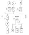
- FIG. 1 illustrates an exemplary embodiment of a vehicle electric system 100.
- the vehicle electric system 100 can be part of an electric vehicle power architecture for a variety of electric and hybrid electric vehicle types, including, but not limited to automobiles, aircraft, watercraft, and various military vehicles.
- the vehicle electric system 100 includes multiple power conversion units (PCUs) 102 ⁇ 110 connected to a common high voltage dc (HVDC) bus 112, where each of the PCUs 102 ⁇ 110 performs one or more functions.
- PCU 102 can perform alternating-to-direct current (AC/DC) conversion to support a synchronous starter/generator 114 for prime mover 116.
- PCU 102 may provide an engine start function as well as an active rectification function to produce HVDC.
- PCU 102 provides multiple functions, the functions are active at different stages of operation. For instance, PCU 102 may initially draw current from the HVDC bus 112 when the synchronous starter/generator 114 starts the prime mover 116. Once the prime mover 116 has been started, the PCU 102 can rectify the output of the synchronous starter/generator 114 to drive current onto the HVDC bus 112.
- the PCU 104 is also referred to as multi-tasking power processor 104.
- the multi-tasking power processor 104 handles both AC/DC conversions and DC/DC conversions.
- the multi-tasking power processor 104 can provide power conversions for a motor 118, energy storage 120, and battery 122, and interface to the HVDC bus 112.
- the multi-tasking power processor 104 combines multiple conversion functions into a single PCU.
- the multi-tasking power processor 104 can convert DC voltage from the HVDC bus 112 into a variable frequency ⁇ variable voltage output to drive the motor 118, which may be a cooling fan.
- the multi-tasking power processor 104 draws direct current from the HVDC bus 112 to store in energy storage 120 or to charge battery 122 using a DC-DC down conversion (buck mode).
- a low voltage direct current (LVDC) bus 124 can connect the multi-tasking power processor 104 to energy storage 120 using low voltage link 126 and to battery 122 using low voltage link 128.
- the multi-tasking power processor 104 can source direct current to the HVDC bus 112 using a DC-DC up conversion (boost mode).
- the vehicle electric system 100 may include a variety of other PCUs to support various functions.
- PCUs 106 and 108 can perform DC/AC conversion to drive traction motors 130 and 132 as part of a traction drive system.
- PCU 110 is a DC/DC converter to source current for loads at one or more voltages, for instance, a 28 VDC accessory bus 134,
- the multi-tasking power processor 104 drives motor 118.
- voltage on the HVDC bus 112 can increase.
- the multi-tasking power processor 104 disconnects the motor 118 and connects the energy storage device 120 or the battery 122 in coordination with active rectification of PCU 102, thus providing effective transient load management.
- the multi-tasking power processor 104 may be configured as a boost DC-DC converter.
- FIG. 2 is an example of an electrical schematic of the multi-tasking power processor 104 of FIG. 1 .
- the multi-tasking power processor 104 includes converter circuitry 200 selectively configurable as a direct current boost converter and a direct current buck converter between an LVDC bus interface 201 and an HVDC bus interface 202.
- the converter circuitry 200 is further configurable as a motor drive between a motor interface 203 and the HVDC bus interface 202.
- Multiple contactors K1, K2, K3, K4, and K5 are used to open or close electrical connections in the multi-tasking power processor 104, reconfiguring the converter circuitry 200 as a function of operating mode.
- Table 1 provides an example of mode based on/off selections for the contactors K1-K5, including a failure mode.
- Contactors K1 are motor interface contactors.
- Contactors K2 and K3 are separately configurable LVDC bus interface contactors, where K2 is an energy storage contactor and K3 is a battery contactor.
- Contactors K4 are phase contactors, and contactor K5 is an HVDC bus interface contactor.
- a controller 204 can control the on/off state of the contactors K1-K5.
- the controller 204 may be integrated within the multi-tasking power processor 104 or included elsewhere in the vehicle electric system 100 of FIG. 1 .
- the controller 204 can also drive on/off states of switches 205 to control phase timing in the multi-tasking power processor 104.
- the controller 204 may monitor motor speed of motor 118 using speed sensor F1.
- the controller 204 can also monitor voltages and currents in the multi-tasking power processor 104 using voltage sensors V1 and V2 and current sensors I1, I2, I3, I4, and I5.
- the HVDC bus interface 202 provides connection points to HVDC bus 112 of FIG. 1 , where contactor K5 is a switching point.
- Current sensor I5 measures the current flowing through contactor K5.
- Voltage sensor V2 measures the voltage drop through resistor R2 between a high side 206 and low side 208 of the HVDC bus interface 202.
- Capacitor C1 is disposed in parallel to resistor R2.
- Switches 205 may include a plurality of power switching devices disposed between the high side 206 and low side 208 of the HVDC bus interface 202 to control current flow on phases 210, 212, and 214.
- Current sensors I1, I2, and I3 can be used to measure the current flowing in phases 210, 212, and 214 respectively.
- Motor interface contactors K1 provide on/off connections between phases 210, 212, and 214 and motor interface 203.
- Contactors K4 provide on/off connections between phases 210, 212, and 214 and inductors L1, L
- Contactor K2 provides an on/off connection between energy storage interface 216 and node 218, where node 218 is coupled to the combination of inductors L1, L2, and L3. Also at node 218, a protection circuit 220 is connected to return 222. Return 222 is a common connection between low side 226 of the LVDC bus interface 201 and the low side 208 of HVDC bus interface 202.
- the protection circuit 220 may be used for bleeding current through resistor R1 and/or diode D1.
- Voltage sensor V1 measures voltage across resistor R1, which may be equivalent to the battery voltage or energy storage voltage depending upon the state of contactors K2 and K3.
- Battery interface 224 and the low side 226 of the LVDC bus interface 201 provide connections to battery 122 of FIG. 1 .
- the low side 226 of the LVDC bus interface 201 may also connect to energy storage 120 of FIG. 1 .
- Current sensor I4 can be used to measure the current flowing to and from energy storage 120 and battery 122 of FIG. 1 depending upon the state of contactors K2 and K3.
- the three inductors L1, L2, and L3 create a three-phase interleaved converter to boost current from energy storage 120 and battery 122 of FIG. 1 or to buck current from the HVDC bus 112 of FIG. 1 to a lower value for storage/charging.
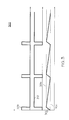
- the current on the three phases 210, 212, and 214 may be interleaved by 120 degrees. It is possible to accommodate both operation of motor 118 and charging of battery 122 by controlling the duty cycle of the multi-tasking power processor 104. In this operating mode, the duty cycle control is a function of inertia of the motor 118 and allowable speed droop.
- FIG. 3 illustrates an example of duty cycle control 300 for multi-tasking power processor 104.
- the converter circuitry 200 of FIG. 2 is configured as a motor drive, resulting in motor acceleration 308 for a period of time.
- the converter circuitry 200 is configured as a direct current buck converter, which enables battery charging 310. Absent acceleration, the inertia of the motor 118 keeps the motor 118 rotating, but the motor speed 302 decays over time until being at or below the lower speed threshold 304.
- the converter circuitry 200 is reconfigured from a direct current buck converter to a motor drive.
- the duty cycle control 300 can be implemented in controller 204 of FIG. 2 using input from speed sensor F1 of FIG. 2 and comparator circuits to establish the lower and upper speed thresholds 304 and 306.
Landscapes
- Engineering & Computer Science (AREA)
- Power Engineering (AREA)
- Transportation (AREA)
- Mechanical Engineering (AREA)
- Dc-Dc Converters (AREA)
- Electric Propulsion And Braking For Vehicles (AREA)
Abstract
Description
- The subject matter disclosed herein generally relates to electrical power distribution, and more particularly to a multi-tasking power processor for a vehicle electric system.
- Electric vehicles, including hybrid vehicles, typically include multiple power electronic converters to perform a variety of functions. Systems such as starter/generation, traction control, environmental control, and transient load management may use a combination of direct and/or alternating current. A vehicle electric system typically includes a plurality of power conversion units (PCUs) connected to a common high voltage direct current bus, where each PCU performs a dedicated function. A greater number of discrete components and individual PCUs used to implement power management and distribution can increase ownership cost, as well as the overall weight and size of the vehicle electric system.
- According to one aspect of the invention, a multi-tasking power processor for a vehicle electric system is provided. The multi-tasking power processor includes a low voltage direct current bus interface, a high voltage direct current bus interface, and a motor interface. The multi-tasking power processor also includes converter circuitry selectively configurable as a direct current boost converter and a direct current buck converter between the low voltage direct current bus interface and the high voltage direct current bus interface. The multi-tasking power processor is further configurable as a motor drive between the motor interface and the high voltage direct current bus interface.
- According to another aspect of the invention, a method for implementing a multi-tasking power processor in a vehicle electric system is provided. The method includes coupling the multi-tasking power processor to a motor, a low voltage direct current bus, and a high voltage direct current bus of the vehicle electric system. The method also includes selectively configuring converter circuitry of the multi-tasking power processor as a direct current boost converter and a direct current buck converter between the low voltage direct current bus and the high voltage direct current bus. The method additionally includes reconfiguring the converter circuitry as a motor drive between the motor and the high voltage direct current bus.
- These and other advantages and features will become more apparent from the following description taken in conjunction with the drawings.
- The subject matter which is regarded as the invention is particularly pointed out and distinctly claimed in the claims at the conclusion of the specification. The foregoing and other features, and advantages of the invention are apparent from the following detailed description taken in conjunction with the accompanying drawings in which:
-
FIG. 1 illustrates an exemplary embodiment of a vehicle electric system including a multi-tasking power processor; -
FIG. 2 is an example of an electrical schematic of a multi-tasking power processor; and -
FIG. 3 is an example of duty cycle control for a multi-tasking power processor. - The detailed description explains embodiments of the invention, together with advantages and features, by way of example with reference to the drawings.
-
FIG. 1 illustrates an exemplary embodiment of a vehicleelectric system 100. The vehicleelectric system 100 can be part of an electric vehicle power architecture for a variety of electric and hybrid electric vehicle types, including, but not limited to automobiles, aircraft, watercraft, and various military vehicles. - The vehicle
electric system 100 includes multiple power conversion units (PCUs) 102 ― 110 connected to a common high voltage dc (HVDC)bus 112, where each of thePCUs 102 ― 110 performs one or more functions. For example, PCU 102 can perform alternating-to-direct current (AC/DC) conversion to support a synchronous starter/generator 114 forprime mover 116. PCU 102 may provide an engine start function as well as an active rectification function to produce HVDC. While PCU 102 provides multiple functions, the functions are active at different stages of operation. For instance, PCU 102 may initially draw current from the HVDCbus 112 when the synchronous starter/generator 114 starts theprime mover 116. Once theprime mover 116 has been started, the PCU 102 can rectify the output of the synchronous starter/generator 114 to drive current onto theHVDC bus 112. - PCU 104 is also referred to as
multi-tasking power processor 104. Themulti-tasking power processor 104 handles both AC/DC conversions and DC/DC conversions. For example, themulti-tasking power processor 104 can provide power conversions for amotor 118,energy storage 120, andbattery 122, and interface to the HVDCbus 112. Rather than using separate PCUs for themotor 118,energy storage 120, andbattery 122, themulti-tasking power processor 104 combines multiple conversion functions into a single PCU. Themulti-tasking power processor 104 can convert DC voltage from theHVDC bus 112 into a variable frequency ― variable voltage output to drive themotor 118, which may be a cooling fan. Themulti-tasking power processor 104 draws direct current from the HVDCbus 112 to store inenergy storage 120 or to chargebattery 122 using a DC-DC down conversion (buck mode). A low voltage direct current (LVDC)bus 124 can connect themulti-tasking power processor 104 toenergy storage 120 usinglow voltage link 126 and tobattery 122 usinglow voltage link 128. Additionally, themulti-tasking power processor 104 can source direct current to the HVDCbus 112 using a DC-DC up conversion (boost mode). - The vehicle
electric system 100 may include a variety of other PCUs to support various functions. For example, PCUs 106 and 108 can perform DC/AC conversion to drivetraction motors VDC accessory bus 134, - During normal vehicle operation, the
multi-tasking power processor 104 drivesmotor 118. During traction drive system regenerative braking, voltage on theHVDC bus 112 can increase. When voltage on theHVDC bus 112 increases, themulti-tasking power processor 104 disconnects themotor 118 and connects theenergy storage device 120 or thebattery 122 in coordination with active rectification ofPCU 102, thus providing effective transient load management. During engine start from thebattery 122 or during quiet vehicle operation, themulti-tasking power processor 104 may be configured as a boost DC-DC converter. -
FIG. 2 is an example of an electrical schematic of themulti-tasking power processor 104 ofFIG. 1 . Themulti-tasking power processor 104 includesconverter circuitry 200 selectively configurable as a direct current boost converter and a direct current buck converter between anLVDC bus interface 201 and anHVDC bus interface 202. Theconverter circuitry 200 is further configurable as a motor drive between amotor interface 203 and theHVDC bus interface 202. Multiple contactors K1, K2, K3, K4, and K5 are used to open or close electrical connections in themulti-tasking power processor 104, reconfiguring theconverter circuitry 200 as a function of operating mode. Table 1 provides an example of mode based on/off selections for the contactors K1-K5, including a failure mode. Contactors K1 are motor interface contactors. Contactors K2 and K3 are separately configurable LVDC bus interface contactors, where K2 is an energy storage contactor and K3 is a battery contactor. Contactors K4 are phase contactors, and contactor K5 is an HVDC bus interface contactor.TABLE 1 - Multi-tasking Power Processor Operating Modes Operating Mode K1 K2 K3 K4 K5 Converter Mode Battery Operation Off Off On On On Boost Motor Operation On Off Off Off On Motor Drive Battery Charge Off Off On On On Buck Energy Store Off On Off On On Buck Failure Mode Off Off Off Off Off Off - A
controller 204 can control the on/off state of the contactors K1-K5. Thecontroller 204 may be integrated within themulti-tasking power processor 104 or included elsewhere in the vehicleelectric system 100 ofFIG. 1 . Thecontroller 204 can also drive on/off states ofswitches 205 to control phase timing in themulti-tasking power processor 104. Thecontroller 204 may monitor motor speed ofmotor 118 using speed sensor F1. Thecontroller 204 can also monitor voltages and currents in themulti-tasking power processor 104 using voltage sensors V1 and V2 and current sensors I1, I2, I3, I4, and I5. - The HVDC
bus interface 202 provides connection points to HVDCbus 112 ofFIG. 1 , where contactor K5 is a switching point. Current sensor I5 measures the current flowing through contactor K5. Voltage sensor V2 measures the voltage drop through resistor R2 between ahigh side 206 andlow side 208 of theHVDC bus interface 202. Capacitor C1 is disposed in parallel to resistor R2.Switches 205 may include a plurality of power switching devices disposed between thehigh side 206 andlow side 208 of theHVDC bus interface 202 to control current flow onphases phases phases motor interface 203. Contactors K4 provide on/off connections betweenphases - Contactor K2 provides an on/off connection between
energy storage interface 216 andnode 218, wherenode 218 is coupled to the combination of inductors L1, L2, and L3. Also atnode 218, aprotection circuit 220 is connected to return 222.Return 222 is a common connection betweenlow side 226 of theLVDC bus interface 201 and thelow side 208 ofHVDC bus interface 202. Theprotection circuit 220 may be used for bleeding current through resistor R1 and/or diode D1. Voltage sensor V1 measures voltage across resistor R1, which may be equivalent to the battery voltage or energy storage voltage depending upon the state of contactors K2 and K3. -
Battery interface 224 and thelow side 226 of theLVDC bus interface 201 provide connections tobattery 122 ofFIG. 1 . Thelow side 226 of theLVDC bus interface 201 may also connect toenergy storage 120 ofFIG. 1 . Current sensor I4 can be used to measure the current flowing to and fromenergy storage 120 andbattery 122 ofFIG. 1 depending upon the state of contactors K2 and K3. - The three inductors L1, L2, and L3 create a three-phase interleaved converter to boost current from
energy storage 120 andbattery 122 ofFIG. 1 or to buck current from theHVDC bus 112 ofFIG. 1 to a lower value for storage/charging. The current on the threephases motor 118 and charging ofbattery 122 by controlling the duty cycle of themulti-tasking power processor 104. In this operating mode, the duty cycle control is a function of inertia of themotor 118 and allowable speed droop. When themotor 118 is a cooling fan, precision control of the cooling fan may not be needed, enabling the cooling fan to operate in a speed band by limiting fan acceleration to a time period where the fan speed has been reduced to a lower speed threshold until the fan speed reaches an upper speed threshold.FIG. 3 illustrates an example ofduty cycle control 300 formulti-tasking power processor 104. - As motor speed 302 of
motor 118 ofFIG. 1 climbs abovelower speed threshold 304 towardsupper speed threshold 306, theconverter circuitry 200 ofFIG. 2 is configured as a motor drive, resulting inmotor acceleration 308 for a period of time. When the motor speed 302 reaches theupper speed threshold 306, theconverter circuitry 200 is configured as a direct current buck converter, which enables battery charging 310. Absent acceleration, the inertia of themotor 118 keeps themotor 118 rotating, but the motor speed 302 decays over time until being at or below thelower speed threshold 304. Again, upon the motor speed 302 reaching or going below thelower speed threshold 304, theconverter circuitry 200 is reconfigured from a direct current buck converter to a motor drive. Theduty cycle control 300 can be implemented incontroller 204 ofFIG. 2 using input from speed sensor F1 ofFIG. 2 and comparator circuits to establish the lower andupper speed thresholds - While the invention has been described in detail in connection with only a limited number of embodiments, it should be readily understood that the invention is not limited to such disclosed embodiments. Rather, the invention can be modified to incorporate any number of variations, alterations, substitutions or equivalent arrangements not heretofore described, but which are commensurate with the scope of the invention as defined by the claims. Additionally, while various embodiments of the invention have been described, it is to be understood that aspects of the invention may include only some of the described embodiments. Accordingly, the invention is not to be seen as limited by the foregoing description, but is only limited by the scope of the appended claims.
Claims (15)
- A multi-tasking power processor (104) for a vehicle electric system (100), comprising:a low voltage direct current bus interface (201);a high voltage direct current bus interface (202);a motor interface (203); andconverter circuitry (200) selectively configurable as a direct current boost converter and a direct current buck converter between the low voltage direct current bus interface (201) and the high voltage direct current bus interface (202), and further configurable as a motor drive between the motor interface (203) and the high voltage direct current bus interface (202).
- The multi-tasking power processor (104) of claim 1 wherein the converter circuitry (200) further comprises motor interface contactors (K1) and low voltage direct current bus interface contactors (K2, K3) selectively configurable to electrically connect and disconnect the motor interface (203) and the low voltage direct current bus interface (201) to the converter circuitry (200).
- The multi-tasking power processor (104) of claim 2 wherein the low voltage direct current bus interface (201) is further comprised of an energy storage interface (216) and a battery interface (224), and the low voltage direct current bus interface contactors (K2, K3) are further comprised of a separately configurable energy storage contactor (K2) and battery contactor (K3).
- The multi-tasking power processor (104) of claim 2 or 3 wherein the converter circuitry (200) further comprises a plurality of switches (205) disposed between a high side (206) and a low side (208) of the high voltage direct current bus interface (202) to control current flow on a plurality of phases (210, 212, 214), and further wherein the plurality of phases (210, 212, 214) are electrically connected to the motor interface contactors (K1); preferably wherein the plurality of switches (205) provide a variable voltage and variable frequency on the plurality of phases (210, 212, 214) when the converter circuitry (200) is selectively configured as the motor drive.
- The multi-tasking power processor (104) of claim 4 wherein the plurality of phases (210, 212, 214) are electrically connected to a plurality of phase contactors (K4), the plurality of phase contactors (K4) are electrically connected to a plurality of inductors (L1, L2, L3) which are coupled at a node (218) electrically connected to the low voltage direct current bus interface contactors (K2, K3).
- The multi-tasking power processor (104) of claim 5 wherein the plurality of inductors (L1, L2, L3) provides a three-phase boost between the low voltage direct current bus interface (201) and the high voltage direct current bus interface (202) when the converter circuitry (200) is selectively configured as the direct current boost converter, and the plurality of inductors (L1, L2, L3) provides a three-phase buck between the low voltage direct current bus interface (201) and the high voltage direct current bus interface (202) when the converter circuitry (200) is selectively configured as the direct current buck converter.
- The multi-tasking power processor (104) of claim 5 or 6 wherein the plurality of phase contactors (K4) electrically disconnect the plurality of inductors (L1, L2, L3) when the converter circuitry (200) is selectively configured as the motor drive.
- The multi-tasking power processor (104) of any preceding claim wherein a controller (204) monitors a motor speed (302) of a motor (118) coupled to the motor interface (203) and selectively configures the converter circuitry (200) as the motor drive in response to the motor speed (302) being at or below a lower speed threshold (304) and selectively configures the converter circuitry (200) as the direct current buck converter in response to the motor speed (302) reaching an upper speed threshold (306); preferably wherein the motor (118) is a cooling fan.
- A method for providing a multi-tasking power processor (104) in a vehicle electric system (100), comprising:coupling the multi-tasking power processor (104) to a motor (118), a low voltage direct current bus (124), and a high voltage direct current bus (112) of the vehicle electric system (100);selectively configuring converter circuitry (200) of the multi-tasking power processor (104) as a direct current boost converter and a direct current buck converter between the low voltage direct current bus (124) and the high voltage direct current bus (112); andreconfiguring the converter circuitry (200) as a motor drive between the motor (118) and the high voltage direct current bus (112).
- The method of claim 9 further wherein selectively configuring the converter circuitry (200) as the direct current boost converter and the direct current buck converter further comprises opening motor interface contactors (K1) and closing low voltage direct current bus interface contactors (K2, K3), and further wherein reconfiguring the converter circuitry (200) as the motor drive further comprises closing the motor interface contactors (K1) and opening the low voltage direct current bus interface contactors (K2, K3).
- The method of claim 10 wherein the low voltage direct current bus (124) is coupled to energy storage (120) and a battery (122), and the low voltage direct current bus interface contactors (K2, K3) are further comprised of a separately configurable energy storage contactor (K2) and battery contactor (K3).
- The method of claim 10 or 11 further comprising:controlling current flow on a plurality of phases (210, 212, 214) using a plurality of switches (205) disposed between a high side (206) and a low side (208) of the high voltage direct current bus (112), wherein the plurality of phases (210, 212, 214) are electrically connected to the motor interface contactors (K1); preferably wherein the plurality of switches (205) provide a variable voltage and variable frequency on the plurality of phases (210, 212, 214) when the converter circuitry (200) is selectively configured as the motor drive.
- The method of claim 12 further comprising:electrically connecting the plurality of phases (210, 212, 214) to a plurality of phase contactors (K4);electrically connecting the plurality of phase contactors (K4) to a plurality of inductors (L1, L2, L3); andcoupling the plurality of inductors (L1, L2, L3) at a node (218) electrically connected to the low voltage direct current bus interface contactors (K2, K3).
- The method of claim 13 further comprising:providing a three-phase boost between the low voltage direct current bus (124) and the high voltage direct current bus (112) through the plurality of inductors (L1, L2, L3) when the converter circuitry (200) is selectively configured as the direct current boost converter; andproviding a three-phase buck between the low voltage direct current bus (124) and the high voltage direct current bus (112) through the plurality of inductors (L1, L2, L3) when the converter circuitry (200) is selectively configured as the direct current buck converter; and/or further comprising:opening the plurality of phase contactors (K4) to electrically disconnect the plurality of inductors (L1, L2, L3) when the converter circuitry (200) is selectively configured as the motor drive.
- The method of any of claims 9 to 14 further comprising:monitoring a motor speed (302) of the motor (118);reconfiguring the converter circuitry (200) as the motor drive in response to the motor speed (302) being at or below a lower speed threshold (304); and selectively configuring the converter circuitry (200) as the direct current buck converter in response to the motor speed (302) reaching an upper speed threshold (306); preferably wherein the motor (118) is a cooling fan.
Applications Claiming Priority (1)
| Application Number | Priority Date | Filing Date | Title |
|---|---|---|---|
| US12/622,597 US8299738B2 (en) | 2009-11-20 | 2009-11-20 | Multi-tasking power processor for a vehicle electric system |
Publications (3)
| Publication Number | Publication Date |
|---|---|
| EP2325971A2 true EP2325971A2 (en) | 2011-05-25 |
| EP2325971A3 EP2325971A3 (en) | 2014-11-19 |
| EP2325971B1 EP2325971B1 (en) | 2021-05-26 |
Family
ID=43719451
Family Applications (1)
| Application Number | Title | Priority Date | Filing Date |
|---|---|---|---|
| EP10251980.8A Active EP2325971B1 (en) | 2009-11-20 | 2010-11-22 | Multi-tasking power processor for a vehicle electric system |
Country Status (2)
| Country | Link |
|---|---|
| US (1) | US8299738B2 (en) |
| EP (1) | EP2325971B1 (en) |
Families Citing this family (8)
| Publication number | Priority date | Publication date | Assignee | Title |
|---|---|---|---|---|
| FR2967847B1 (en) * | 2010-11-23 | 2015-06-26 | Hispano Suiza Sa | METHOD AND ARCHITECTURE FOR PROCESSING REGENERATED ELECTRIC ENERGY OF AN AIRCRAFT |
| DE102013205698A1 (en) * | 2013-03-28 | 2014-10-02 | Siemens Aktiengesellschaft | Device for controlling a drive device in a rail vehicle |
| WO2014179288A1 (en) * | 2013-04-29 | 2014-11-06 | Transistor Devices, Inc. D/B/A Tdi Power | Usb power distribution management system |
| US9969273B2 (en) * | 2016-07-12 | 2018-05-15 | Hamilton Sundstrand Corporation | Integrated modular electric power system for a vehicle |
| US11043880B2 (en) | 2016-11-10 | 2021-06-22 | Hamilton Sunstrand Corporation | Electric power generating system with a synchronous generator |
| US10498274B2 (en) | 2016-11-10 | 2019-12-03 | Hamilton Sundstrand Corporation | High voltage direct current system for a vehicle |
| JP6832775B2 (en) * | 2017-03-30 | 2021-02-24 | 本田技研工業株式会社 | Engine generator |
| JP6875907B2 (en) * | 2017-03-30 | 2021-05-26 | 本田技研工業株式会社 | Generator system |
Family Cites Families (16)
| Publication number | Priority date | Publication date | Assignee | Title |
|---|---|---|---|---|
| JPH0630505A (en) * | 1992-01-31 | 1994-02-04 | Fuji Electric Co Ltd | Electric system for electric automobile |
| JPH0654410A (en) * | 1992-06-05 | 1994-02-25 | Fuji Electric Co Ltd | Electric system for electric motor vehicle |
| US6504730B1 (en) * | 2001-07-23 | 2003-01-07 | Hamilton Sundstrand Corporation | Serviceable power modules for a power distribution assembly |
| US7362557B2 (en) * | 2004-03-30 | 2008-04-22 | Continental Automotive Systems U.S. Inc. | Method, apparatus and article for bi-directional DC/DC power conversion |
| DE102004041511A1 (en) * | 2004-08-27 | 2006-03-02 | Robert Bosch Gmbh | Voltage regulator with overvoltage protection |
| US7112944B1 (en) * | 2005-04-19 | 2006-09-26 | Honeywell International Inc. | Electrical power system for multi-use power conditioning and engine start |
| US7675192B2 (en) * | 2005-06-15 | 2010-03-09 | Gm Global Technology Operations, Inc. | Active DC bus filter for fuel cell applications |
| US8148842B2 (en) * | 2006-02-20 | 2012-04-03 | Hamilton Sundstrand Corporation | Electrical power generation system having multiple secondary power distribution assemblies with integral power conversion |
| US7349813B2 (en) * | 2006-05-16 | 2008-03-25 | Dresser, Inc. | Fault tolerant power system architecture for fluid flow measurement systems |
| US7439715B2 (en) * | 2006-05-22 | 2008-10-21 | Hamilton Sundstrand Corporation | Dual source power generating system |
| US7733039B2 (en) * | 2006-10-19 | 2010-06-08 | Ut-Battelle, Llc | Electric vehicle system for charging and supplying electrical power |
| US7612514B2 (en) * | 2006-11-09 | 2009-11-03 | Honeywell International Inc. | Architecture and a multiple function power converter for aircraft |
| US8217616B2 (en) * | 2007-11-02 | 2012-07-10 | HJamilton Sundstrand Corporation | Electric motor control with buck boost converter |
| US8120290B2 (en) * | 2008-10-13 | 2012-02-21 | General Electric Company | Energy management system to improve efficiency of electric and hybrid drive trains |
| US8013548B2 (en) * | 2008-10-14 | 2011-09-06 | General Electric Company | System, vehicle and related method |
| US8026638B2 (en) * | 2009-08-11 | 2011-09-27 | General Electric Company | System for multiple energy storage and management and method of making same |
-
2009
- 2009-11-20 US US12/622,597 patent/US8299738B2/en active Active
-
2010
- 2010-11-22 EP EP10251980.8A patent/EP2325971B1/en active Active
Non-Patent Citations (1)
| Title |
|---|
| None |
Also Published As
| Publication number | Publication date |
|---|---|
| US20110121769A1 (en) | 2011-05-26 |
| US8299738B2 (en) | 2012-10-30 |
| EP2325971A3 (en) | 2014-11-19 |
| EP2325971B1 (en) | 2021-05-26 |
Similar Documents
| Publication | Publication Date | Title |
|---|---|---|
| EP2325971B1 (en) | Multi-tasking power processor for a vehicle electric system | |
| JP6228586B2 (en) | Electric vehicle | |
| US9809121B2 (en) | Apparatus for energy transfer using converter and method of manufacturing same | |
| US8026638B2 (en) | System for multiple energy storage and management and method of making same | |
| US6486568B1 (en) | Power system using a multi-functional power interface unit | |
| US11799392B2 (en) | Low-volt decoupling from a modular energy store converter system | |
| JP6736370B2 (en) | Power conversion system | |
| KR20170094781A (en) | Apparatus for transferring energy using power electronics and machine inductance and method of manufacturing same | |
| US20190031125A1 (en) | Electric system architecture for range extended electric vehicles | |
| EP2562021B1 (en) | Regenerative load electric power management systems and methods | |
| US11834033B2 (en) | Regenerative braking system and electrically-driven work vehicle using regenerative braking system | |
| EP2994973A1 (en) | Hybrid energy sourced battery or super-capacitor fed drive topologies | |
| WO2011004588A1 (en) | Electric vehicle control device | |
| KR102346456B1 (en) | Power Control System for a Battery Driven Elevator | |
| JP5105154B2 (en) | Control device | |
| US10680533B1 (en) | Common layout rectifier or converter | |
| Al-Sheikh et al. | Study on power converters used in hybrid vehicles with monitoring and diagnostics techniques | |
| US9457683B2 (en) | Method for discharging at least one capacitor of an electric circuit | |
| US20170326997A1 (en) | Method for recharging energy accumulation means fitted to an electric or hybrid vehicle | |
| US20150349674A1 (en) | Multiaxial driving apparatus | |
| KR20210051227A (en) | Power apparatus on board charger and electric motor driver of electric vehicle |
Legal Events
| Date | Code | Title | Description |
|---|---|---|---|
| PUAI | Public reference made under article 153(3) epc to a published international application that has entered the european phase |
Free format text: ORIGINAL CODE: 0009012 |
|
| AK | Designated contracting states |
Kind code of ref document: A2 Designated state(s): AL AT BE BG CH CY CZ DE DK EE ES FI FR GB GR HR HU IE IS IT LI LT LU LV MC MK MT NL NO PL PT RO RS SE SI SK SM TR |
|
| AX | Request for extension of the european patent |
Extension state: BA ME |
|
| PUAL | Search report despatched |
Free format text: ORIGINAL CODE: 0009013 |
|
| AK | Designated contracting states |
Kind code of ref document: A3 Designated state(s): AL AT BE BG CH CY CZ DE DK EE ES FI FR GB GR HR HU IE IS IT LI LT LU LV MC MK MT NL NO PL PT RO RS SE SI SK SM TR |
|
| AX | Request for extension of the european patent |
Extension state: BA ME |
|
| RIC1 | Information provided on ipc code assigned before grant |
Ipc: B60L 11/18 20060101ALI20141015BHEP Ipc: H02J 3/38 20060101AFI20141015BHEP |
|
| 17P | Request for examination filed |
Effective date: 20150519 |
|
| RBV | Designated contracting states (corrected) |
Designated state(s): AL AT BE BG CH CY CZ DE DK EE ES FI FR GB GR HR HU IE IS IT LI LT LU LV MC MK MT NL NO PL PT RO RS SE SI SK SM TR |
|
| STAA | Information on the status of an ep patent application or granted ep patent |
Free format text: STATUS: EXAMINATION IS IN PROGRESS |
|
| 17Q | First examination report despatched |
Effective date: 20170717 |
|
| RIC1 | Information provided on ipc code assigned before grant |
Ipc: H02P 27/06 20060101ALI20200702BHEP Ipc: B60L 53/20 20190101ALI20200702BHEP Ipc: H02J 3/38 20060101AFI20200702BHEP |
|
| GRAP | Despatch of communication of intention to grant a patent |
Free format text: ORIGINAL CODE: EPIDOSNIGR1 |
|
| STAA | Information on the status of an ep patent application or granted ep patent |
Free format text: STATUS: GRANT OF PATENT IS INTENDED |
|
| INTG | Intention to grant announced |
Effective date: 20200811 |
|
| GRAJ | Information related to disapproval of communication of intention to grant by the applicant or resumption of examination proceedings by the epo deleted |
Free format text: ORIGINAL CODE: EPIDOSDIGR1 |
|
| STAA | Information on the status of an ep patent application or granted ep patent |
Free format text: STATUS: EXAMINATION IS IN PROGRESS |
|
| INTC | Intention to grant announced (deleted) | ||
| RAP1 | Party data changed (applicant data changed or rights of an application transferred) |
Owner name: HAMILTON SUNDSTRAND CORPORATION |
|
| RIN1 | Information on inventor provided before grant (corrected) |
Inventor name: ROZMAN, GREGORY I. Inventor name: NGUYEN, VIETSON M |
|
| GRAP | Despatch of communication of intention to grant a patent |
Free format text: ORIGINAL CODE: EPIDOSNIGR1 |
|
| STAA | Information on the status of an ep patent application or granted ep patent |
Free format text: STATUS: GRANT OF PATENT IS INTENDED |
|
| INTG | Intention to grant announced |
Effective date: 20210112 |
|
| GRAS | Grant fee paid |
Free format text: ORIGINAL CODE: EPIDOSNIGR3 |
|
| GRAA | (expected) grant |
Free format text: ORIGINAL CODE: 0009210 |
|
| STAA | Information on the status of an ep patent application or granted ep patent |
Free format text: STATUS: THE PATENT HAS BEEN GRANTED |
|
| AK | Designated contracting states |
Kind code of ref document: B1 Designated state(s): AL AT BE BG CH CY CZ DE DK EE ES FI FR GB GR HR HU IE IS IT LI LT LU LV MC MK MT NL NO PL PT RO RS SE SI SK SM TR |
|
| REG | Reference to a national code |
Ref country code: GB Ref legal event code: FG4D |
|
| REG | Reference to a national code |
Ref country code: CH Ref legal event code: EP |
|
| REG | Reference to a national code |
Ref country code: DE Ref legal event code: R096 Ref document number: 602010067034 Country of ref document: DE |
|
| REG | Reference to a national code |
Ref country code: AT Ref legal event code: REF Ref document number: 1397201 Country of ref document: AT Kind code of ref document: T Effective date: 20210615 |
|
| REG | Reference to a national code |
Ref country code: IE Ref legal event code: FG4D |
|
| REG | Reference to a national code |
Ref country code: LT Ref legal event code: MG9D |
|
| REG | Reference to a national code |
Ref country code: AT Ref legal event code: MK05 Ref document number: 1397201 Country of ref document: AT Kind code of ref document: T Effective date: 20210526 |
|
| PG25 | Lapsed in a contracting state [announced via postgrant information from national office to epo] |
Ref country code: LT Free format text: LAPSE BECAUSE OF FAILURE TO SUBMIT A TRANSLATION OF THE DESCRIPTION OR TO PAY THE FEE WITHIN THE PRESCRIBED TIME-LIMIT Effective date: 20210526 Ref country code: FI Free format text: LAPSE BECAUSE OF FAILURE TO SUBMIT A TRANSLATION OF THE DESCRIPTION OR TO PAY THE FEE WITHIN THE PRESCRIBED TIME-LIMIT Effective date: 20210526 Ref country code: AT Free format text: LAPSE BECAUSE OF FAILURE TO SUBMIT A TRANSLATION OF THE DESCRIPTION OR TO PAY THE FEE WITHIN THE PRESCRIBED TIME-LIMIT Effective date: 20210526 Ref country code: BG Free format text: LAPSE BECAUSE OF FAILURE TO SUBMIT A TRANSLATION OF THE DESCRIPTION OR TO PAY THE FEE WITHIN THE PRESCRIBED TIME-LIMIT Effective date: 20210826 Ref country code: HR Free format text: LAPSE BECAUSE OF FAILURE TO SUBMIT A TRANSLATION OF THE DESCRIPTION OR TO PAY THE FEE WITHIN THE PRESCRIBED TIME-LIMIT Effective date: 20210526 |
|
| REG | Reference to a national code |
Ref country code: NL Ref legal event code: MP Effective date: 20210526 |
|
| PG25 | Lapsed in a contracting state [announced via postgrant information from national office to epo] |
Ref country code: IS Free format text: LAPSE BECAUSE OF FAILURE TO SUBMIT A TRANSLATION OF THE DESCRIPTION OR TO PAY THE FEE WITHIN THE PRESCRIBED TIME-LIMIT Effective date: 20210926 Ref country code: LV Free format text: LAPSE BECAUSE OF FAILURE TO SUBMIT A TRANSLATION OF THE DESCRIPTION OR TO PAY THE FEE WITHIN THE PRESCRIBED TIME-LIMIT Effective date: 20210526 Ref country code: GR Free format text: LAPSE BECAUSE OF FAILURE TO SUBMIT A TRANSLATION OF THE DESCRIPTION OR TO PAY THE FEE WITHIN THE PRESCRIBED TIME-LIMIT Effective date: 20210827 Ref country code: SE Free format text: LAPSE BECAUSE OF FAILURE TO SUBMIT A TRANSLATION OF THE DESCRIPTION OR TO PAY THE FEE WITHIN THE PRESCRIBED TIME-LIMIT Effective date: 20210526 Ref country code: RS Free format text: LAPSE BECAUSE OF FAILURE TO SUBMIT A TRANSLATION OF THE DESCRIPTION OR TO PAY THE FEE WITHIN THE PRESCRIBED TIME-LIMIT Effective date: 20210526 Ref country code: NO Free format text: LAPSE BECAUSE OF FAILURE TO SUBMIT A TRANSLATION OF THE DESCRIPTION OR TO PAY THE FEE WITHIN THE PRESCRIBED TIME-LIMIT Effective date: 20210826 Ref country code: PL Free format text: LAPSE BECAUSE OF FAILURE TO SUBMIT A TRANSLATION OF THE DESCRIPTION OR TO PAY THE FEE WITHIN THE PRESCRIBED TIME-LIMIT Effective date: 20210526 Ref country code: PT Free format text: LAPSE BECAUSE OF FAILURE TO SUBMIT A TRANSLATION OF THE DESCRIPTION OR TO PAY THE FEE WITHIN THE PRESCRIBED TIME-LIMIT Effective date: 20210927 |
|
| PG25 | Lapsed in a contracting state [announced via postgrant information from national office to epo] |
Ref country code: NL Free format text: LAPSE BECAUSE OF FAILURE TO SUBMIT A TRANSLATION OF THE DESCRIPTION OR TO PAY THE FEE WITHIN THE PRESCRIBED TIME-LIMIT Effective date: 20210526 |
|
| PG25 | Lapsed in a contracting state [announced via postgrant information from national office to epo] |
Ref country code: DK Free format text: LAPSE BECAUSE OF FAILURE TO SUBMIT A TRANSLATION OF THE DESCRIPTION OR TO PAY THE FEE WITHIN THE PRESCRIBED TIME-LIMIT Effective date: 20210526 Ref country code: CZ Free format text: LAPSE BECAUSE OF FAILURE TO SUBMIT A TRANSLATION OF THE DESCRIPTION OR TO PAY THE FEE WITHIN THE PRESCRIBED TIME-LIMIT Effective date: 20210526 Ref country code: EE Free format text: LAPSE BECAUSE OF FAILURE TO SUBMIT A TRANSLATION OF THE DESCRIPTION OR TO PAY THE FEE WITHIN THE PRESCRIBED TIME-LIMIT Effective date: 20210526 Ref country code: SM Free format text: LAPSE BECAUSE OF FAILURE TO SUBMIT A TRANSLATION OF THE DESCRIPTION OR TO PAY THE FEE WITHIN THE PRESCRIBED TIME-LIMIT Effective date: 20210526 Ref country code: SK Free format text: LAPSE BECAUSE OF FAILURE TO SUBMIT A TRANSLATION OF THE DESCRIPTION OR TO PAY THE FEE WITHIN THE PRESCRIBED TIME-LIMIT Effective date: 20210526 Ref country code: RO Free format text: LAPSE BECAUSE OF FAILURE TO SUBMIT A TRANSLATION OF THE DESCRIPTION OR TO PAY THE FEE WITHIN THE PRESCRIBED TIME-LIMIT Effective date: 20210526 Ref country code: ES Free format text: LAPSE BECAUSE OF FAILURE TO SUBMIT A TRANSLATION OF THE DESCRIPTION OR TO PAY THE FEE WITHIN THE PRESCRIBED TIME-LIMIT Effective date: 20210526 |
|
| REG | Reference to a national code |
Ref country code: DE Ref legal event code: R097 Ref document number: 602010067034 Country of ref document: DE |
|
| PLBE | No opposition filed within time limit |
Free format text: ORIGINAL CODE: 0009261 |
|
| STAA | Information on the status of an ep patent application or granted ep patent |
Free format text: STATUS: NO OPPOSITION FILED WITHIN TIME LIMIT |
|
| 26N | No opposition filed |
Effective date: 20220301 |
|
| PG25 | Lapsed in a contracting state [announced via postgrant information from national office to epo] |
Ref country code: IS Free format text: LAPSE BECAUSE OF FAILURE TO SUBMIT A TRANSLATION OF THE DESCRIPTION OR TO PAY THE FEE WITHIN THE PRESCRIBED TIME-LIMIT Effective date: 20210926 Ref country code: AL Free format text: LAPSE BECAUSE OF FAILURE TO SUBMIT A TRANSLATION OF THE DESCRIPTION OR TO PAY THE FEE WITHIN THE PRESCRIBED TIME-LIMIT Effective date: 20210526 |
|
| PG25 | Lapsed in a contracting state [announced via postgrant information from national office to epo] |
Ref country code: MC Free format text: LAPSE BECAUSE OF FAILURE TO SUBMIT A TRANSLATION OF THE DESCRIPTION OR TO PAY THE FEE WITHIN THE PRESCRIBED TIME-LIMIT Effective date: 20210526 |
|
| REG | Reference to a national code |
Ref country code: CH Ref legal event code: PL |
|
| PG25 | Lapsed in a contracting state [announced via postgrant information from national office to epo] |
Ref country code: LU Free format text: LAPSE BECAUSE OF NON-PAYMENT OF DUE FEES Effective date: 20211122 Ref country code: IT Free format text: LAPSE BECAUSE OF FAILURE TO SUBMIT A TRANSLATION OF THE DESCRIPTION OR TO PAY THE FEE WITHIN THE PRESCRIBED TIME-LIMIT Effective date: 20210526 Ref country code: BE Free format text: LAPSE BECAUSE OF NON-PAYMENT OF DUE FEES Effective date: 20211130 |
|
| REG | Reference to a national code |
Ref country code: BE Ref legal event code: MM Effective date: 20211130 |
|
| PG25 | Lapsed in a contracting state [announced via postgrant information from national office to epo] |
Ref country code: IE Free format text: LAPSE BECAUSE OF NON-PAYMENT OF DUE FEES Effective date: 20211122 |
|
| PG25 | Lapsed in a contracting state [announced via postgrant information from national office to epo] |
Ref country code: HU Free format text: LAPSE BECAUSE OF FAILURE TO SUBMIT A TRANSLATION OF THE DESCRIPTION OR TO PAY THE FEE WITHIN THE PRESCRIBED TIME-LIMIT; INVALID AB INITIO Effective date: 20101122 Ref country code: CY Free format text: LAPSE BECAUSE OF FAILURE TO SUBMIT A TRANSLATION OF THE DESCRIPTION OR TO PAY THE FEE WITHIN THE PRESCRIBED TIME-LIMIT Effective date: 20210526 |
|
| P01 | Opt-out of the competence of the unified patent court (upc) registered |
Effective date: 20230522 |
|
| PG25 | Lapsed in a contracting state [announced via postgrant information from national office to epo] |
Ref country code: LI Free format text: LAPSE BECAUSE OF NON-PAYMENT OF DUE FEES Effective date: 20220630 Ref country code: CH Free format text: LAPSE BECAUSE OF NON-PAYMENT OF DUE FEES Effective date: 20220630 |
|
| PGFP | Annual fee paid to national office [announced via postgrant information from national office to epo] |
Ref country code: GB Payment date: 20231019 Year of fee payment: 14 |
|
| PGFP | Annual fee paid to national office [announced via postgrant information from national office to epo] |
Ref country code: FR Payment date: 20231019 Year of fee payment: 14 Ref country code: DE Payment date: 20231019 Year of fee payment: 14 |
|
| PG25 | Lapsed in a contracting state [announced via postgrant information from national office to epo] |
Ref country code: MK Free format text: LAPSE BECAUSE OF FAILURE TO SUBMIT A TRANSLATION OF THE DESCRIPTION OR TO PAY THE FEE WITHIN THE PRESCRIBED TIME-LIMIT Effective date: 20210526 |