EP2274825B1 - Power supply device - Google Patents
Power supply device Download PDFInfo
- Publication number
- EP2274825B1 EP2274825B1 EP09741948.5A EP09741948A EP2274825B1 EP 2274825 B1 EP2274825 B1 EP 2274825B1 EP 09741948 A EP09741948 A EP 09741948A EP 2274825 B1 EP2274825 B1 EP 2274825B1
- Authority
- EP
- European Patent Office
- Prior art keywords
- power supply
- supply device
- converter
- power converter
- power
- Prior art date
- Legal status (The legal status is an assumption and is not a legal conclusion. Google has not performed a legal analysis and makes no representation as to the accuracy of the status listed.)
- Active
Links
- 238000004146 energy storage Methods 0.000 claims description 17
- 239000004065 semiconductor Substances 0.000 claims description 16
- 239000003990 capacitor Substances 0.000 claims description 15
- 238000004804 winding Methods 0.000 description 10
- 230000005540 biological transmission Effects 0.000 description 6
- 238000010586 diagram Methods 0.000 description 3
- 230000008878 coupling Effects 0.000 description 2
- 238000010168 coupling process Methods 0.000 description 2
- 238000005859 coupling reaction Methods 0.000 description 2
- 238000005516 engineering process Methods 0.000 description 2
- 230000007704 transition Effects 0.000 description 2
- 238000004891 communication Methods 0.000 description 1
- 238000006073 displacement reaction Methods 0.000 description 1
- 230000002349 favourable effect Effects 0.000 description 1
- 238000009413 insulation Methods 0.000 description 1
- 238000004519 manufacturing process Methods 0.000 description 1
- 210000002023 somite Anatomy 0.000 description 1
Images


Classifications
-
- H—ELECTRICITY
- H02—GENERATION; CONVERSION OR DISTRIBUTION OF ELECTRIC POWER
- H02M—APPARATUS FOR CONVERSION BETWEEN AC AND AC, BETWEEN AC AND DC, OR BETWEEN DC AND DC, AND FOR USE WITH MAINS OR SIMILAR POWER SUPPLY SYSTEMS; CONVERSION OF DC OR AC INPUT POWER INTO SURGE OUTPUT POWER; CONTROL OR REGULATION THEREOF
- H02M7/00—Conversion of ac power input into dc power output; Conversion of dc power input into ac power output
- H02M7/42—Conversion of dc power input into ac power output without possibility of reversal
- H02M7/44—Conversion of dc power input into ac power output without possibility of reversal by static converters
- H02M7/48—Conversion of dc power input into ac power output without possibility of reversal by static converters using discharge tubes with control electrode or semiconductor devices with control electrode
- H02M7/483—Converters with outputs that each can have more than two voltages levels
- H02M7/4835—Converters with outputs that each can have more than two voltages levels comprising two or more cells, each including a switchable capacitor, the capacitors having a nominal charge voltage which corresponds to a given fraction of the input voltage, and the capacitors being selectively connected in series to determine the instantaneous output voltage
Definitions
- the invention relates to a power supply device according to the preamble of claim 1.
- variable-speed drives consisting of an electric motor and a pump or a compressor, supplied on the seabed with energy from an electrical supply network on land.
- the distance between infeed on land and propulsion at the seabed can be several hundred kilometers with sea depths of several kilometers.
- Variable speed drives for underwater applications also referred to as subsea applications, are used, for example, in oil and gas production on the seabed. These variable-speed drives are known to be powered by means of a voltage source inverter from an electrical supply network with energy.
- inverter topologies include 3-level neutral-point-clamped (3L-NPC) 12-pulse diode feed, 4-level flying capacitors (4L-FC) with 12-pulse diode feed, Series Connected H-Bridge cell inverters with 2-level H-bridges per cell (SC-HB (2L)) and a Series-Connected H-Bridge cell inverter with 3-level H-bridge per cell (SC-HB (3L)).
- Modular power converter concept for mains coupling application at high voltages is a converter with a mains and load side power converter, the DC side connected to each other electrically conductive , in which a modular multipoint power converter, also referred to as a modular multilevel converter (M2C), is used as the power converter.
- M2C modular multilevel converter
- Such a voltage source converter with a mains and load side converter in M2C topology has no voltage intermediate circuit constructed from intermediate circuit capacitors more compared to the already described voltage source inverter.
- Each valve branch of each phase module of the inverter in M2C topology has at least one two-pole subsystem. The number of subsystems used in each valve branch determines the frequency of a phase output voltage.
- FIG. 2 a further known power supply device of a arranged on the seabed speed variable drive is shown.
- This embodiment differs from the embodiment according to FIG. 1 in that the AC cable 14 is linked by means of a transformer 32 to outputs of the self-commutated pulse-controlled converter 12 of the voltage intermediate-circuit converter 2.
- this AC power cable 14 is connected by means of a second transformer 34 to terminals of the seabed electric motor 14.
- a generated inverter voltage is transformed to a potential higher than the potential of the rated voltage of the electric motor 4. After transmission, this potential is transformed back to nominal potential of the motor.
- the increased transmission voltage results in lower ohmic power losses.
- the AC cable 14 may have a smaller cable cross-section, thereby allowing a more favorable design of the cable 14. This allows a greater distance between inverter 2 and motor 4 over the embodiment according to FIG. 1 be bridged.
- the voltage intermediate-circuit converter 2 with mains-side converter transformer 6 is according to FIG. 3 arranged on the seabed in the immediate vicinity of the electric motor 4 of the variable speed drive.
- a mains transformer 36 is provided, which is the primary side connected to the dining supply network 8, in particular with the feed point 26, and the secondary side electrically connected to the AC cable 14.
- FIG. 4 is a multi-motor variant of the power supply device according to FIG. 4 shown schematically.
- Each motor of a variable-speed drive is coupled to a voltage source inverter 2 with line-side converter transformer 6.
- the AC power cable 14 is linked to an AC busbar 38 to which are connected the plurality of power converter powered drives.
- the AC cable 14 may be provided on the load side of the seabed with another transformer 40, which is the secondary side connected to the AC busbar 38. Since this further transformer 40 is not absolutely necessary, this is shown by broken lines. With this further transformer 40, the AC busbar 38 has a potential below the potential of the transmission voltage, but above the potential of the rated voltage of the electric motor 4 of a variable-speed drive.
- the distance between entry point 26 on land and drive at the seabed is the same as in the other variants FIGS. 1 to 3 still limited.
- the number of plant parts on the seabed has multiplied. All plant components arranged at the seabed are encapsulated, in particular each be housed in a pressure vessel.
- the one self-commutated pulse-controlled converter is arranged by means of a mains transformer at a feed point of a feeding network on land, whereas the second self-commutated pulse-controlled converter is arranged on a platform on the sea.
- a direct voltage cable a submarine cable is provided, which has a length of about 300km. Between these two converters no communication is necessary. Only the value of the DC voltage at both ends of the DC cable is needed.
- the converter station on land regulates the transmission voltage and the converter station on the platform at sea regulates the active power. Also in this power supply device, the distance between the feed point and platform is also limited.
- the invention is based on the object, the known power supply device such that the distance between the feed point to land and drive at the seabed is much larger.
- a power converter with distributed energy storage is provided as load-side self-commutated power converter of the upper and lower valve branch of each phase module at least two electrically connected in series bipolar subsystems
- the power supply device according to the invention no energy storage in the DC intermediate circuit more, so that now that the network-side converter and the load-side converter of the power supply device according to the invention electrically connecting DC cables can bridge much greater distances.
- the power converter with distributed energy stores of the power supply device according to the invention can be arranged on the motor to be fed on the seabed and its power converter on shore.
- a power converter with a plurality of bipolar subsystems as a load-side power converter of the power supply device of the voltage source inverter can be divided between land and seabed.
- the load-side converter with distributed energy storage of this power supply device on the seabed.
- the value of the converter output voltage and thus the motor voltage is determined, no transformer is needed at the seabed.
- the finely graded output voltage form of the load-side power converter with distributed energy storage devices of the power supply device according to the invention submerged motors with reduced requirements for the winding insulation. Since a high motor voltage can still be set regardless of the use of a transformer, connecting lines and feedthroughs to the motor can be designed for smaller currents. In addition, it can be avoided at higher power motors with multiple winding systems.
- the load-side converter with distributed energy stores of the power supply device per valve branch only consists of a number of electrically connected in series bipolar subsystems, the availability of the power supply device can be substantially increased by adding redundant bipolar subsystems.
- signal electronics of the load-side arranged on the seabed power converter with distributed energy storage on land is arranged.
- This signal electronics is connected by means of a data cable signal technology with control inputs of the load-side converter with distributed energy storage on the seabed.
- the network-side uncontrolled power converter by means of the DC cable with a arranged on seabed DC busbar is electrically conductively connected.
- a plurality of load-side converters with distributed energy storage can be connected in each case with an output-side motor of a variable speed drive.
- FIG. 5 a first variant of the power supply device according to the invention is shown schematically.
- 42 denotes a load-side power converter with distributed energy stores
- 44 denotes a DC cable
- 46 denotes a control unit.
- the network side and the Load-side power converters 10 and 42 are connected to one another by means of the DC cable 44 on the DC voltage side.
- the control unit 46 of this load-side power converter 42 with distributed energy stores is connected by means of a data cable 18 with the signal electronics 16 of the power supply device, which is associated with the network-side converter 10.
- the network-side power converter 10 which is designed as an uncontrolled power converter, is connected on the alternating voltage side by means of the power transformer 36 to the feed point 26 of the feeding supply network 8.
- the load-side power converter 42 is arranged with distributed energy storage on the seabed. All other components of this power supply device are arranged on land. The transition from land to sea is also indicated by a wavy line 30 in this figure.
- a line-side converter 10 a diode feed is provided, which is designed in the simplest case 6-pulse. If current harmonics in the network are not to be present if possible, and if so, then only with a small amplitude, the diode feed 10 must be designed, for example, 12, 18 or 24-pulse.
- FIG. 6 is a block diagram of an advantageous embodiment of the power supply device according to the invention schematically illustrated.
- the diode feed 10 has two 6-pulse diode bridges 48 and 50, which are each connected on the alternating voltage side to a secondary winding 22 and 20 of the converter transformer 6 and the DC side electrically in series.
- the load-side power converter 42 with distributed energy storage devices has a plurality of phase modules 52, which are electrically connected in parallel on the DC voltage side.
- a positive and negative DC bus bar P 0W and N 0W are provided for the parallel connection of these phase modules 52.
- a positive and negative DC bus bar P 0W and N 0W are provided. Between these two DC busbars P 0W and N 0W falls from an unspecified DC voltage.
- Each phase module 52 has an upper one and a lower valve branch T1, T2 and T3, T4 and T5, T6, respectively.
- Each valve branch T1,..., T6 has at least two two-pole subsystems 54.
- each valve branch has four two-pole subsystems 54.
- the bipolar subsystems 54 are electrically connected in series. Embodiments of these bipolar subsystems 54 are shown in FIGS FIGS. 7 and 8 shown.
- Each connection point of two valve branches T1, T2 or T3, T4 or T5, T6 form an AC-side terminal L1 or L2 or L3.
- At these AC-side terminals L1, L2 and L3 is in the FIG. 5 shown electric motor 4 connected.
- the DC busbars P 0W and N 0W of the load-side power converter 42 with distributed energy storage devices and the DC busbars P 0G and N 0G of the network-side power converter are electrically conductively connected to each other by means of the DC cable 44.
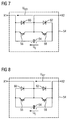
- FIG. 7 A first embodiment of a bipolar subsystem 54 is shown.
- This bipolar subsystem 54 has two turn-off semiconductor switches 56 and 58, two diodes 60 and 62 and a unipolar storage capacitor 64.
- the two turn-off semiconductor switches 56 and 58 are electrically connected in series, wherein this series circuit is electrically connected in parallel to the storage capacitor 64.
- Each turn-off semiconductor switch 56 and 58, one of the two diodes 60 and 62 is electrically connected in parallel, that this is connected in antiparallel to the corresponding turn-off semiconductor switch 56 and 58.
- the unipolar storage capacitor 64 of the bipolar subsystem 54 consists of either a capacitor or a capacitor bank of a plurality of such capacitors with a resulting capacitance C 0 .
- connection point of emitter of the turn-off semiconductor switch 56 and anode of the diode 60 form a terminal X1 of the subsystem 54.
- connection point of the two turn-off semiconductor switch 56th and 58 and the two diodes 60 and 62 form a second terminal X2 of the bipolar subsystem 54.
- connection point forms the first connection terminal X1.
- the connection point of drain of the turn-off semiconductor switch 58 and cathode of the diode 62 forms the second terminal X2 of the bipolar subsystem 54th
- the bipolar subsystem 54 may assume three switching states. In the switching state I, the turn-off semiconductor switch 56 is turned on and the turn-off semiconductor switch 58 is turned off. In this switching state I, the terminal voltage U X21 of the bipolar subsystem 54 is equal to zero. In switching state II, the turn-off semiconductor switch 56 are turned off and the turn-off semiconductor switch 58 is turned on. In this switching state II, the terminal voltage U X21 of the bipolar subsystem 54 is equal to the voltage U C on the storage capacitor 64. In normal, trouble-free operation, only these two switching states I and II are used. In switching state III, both turn-off semiconductor switches 56 and 58 are turned off.
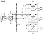
- FIG. 9 a second variant of the power supply device according to the invention is illustrated schematically.
- This second variant differs in that a DC busbar 66 is provided.
- three load-side converter 42 are connected with distributed energy storage devices each with a load-side motor 4 of a variable speed drive.
- This DC busbar 66 is linked by means of the DC cable 44 with DC terminals of the network-side converter 10.
- a data busbar 68 is provided, on the one hand, the control units 46 of the load-side power converter 42 with distributed energy storage and on the other hand, the data cable 18 are connected.
- the land-based signal electronics 16 of the power supply device according to the invention in each case with a control unit 46 of a respective arranged on the seabed load-side converter 42 with distributed energy storage signal technology connected.
- a DC busbar 66 By using a DC busbar 66, the cable costs for a multi-motor drive and the effort for assembly are reduced.
- variable-speed drives of subsea applications for example oil and gas conveyors
- a feeding supply network wherein the distance between the feed on land and the drive on the seabed can be several hundred kilometers at sea depths of several kilometers
Landscapes
- Engineering & Computer Science (AREA)
- Power Engineering (AREA)
- Inverter Devices (AREA)
- Rectifiers (AREA)
- Control Of Eletrric Generators (AREA)
- Other Liquid Machine Or Engine Such As Wave Power Use (AREA)
Description
Die Erfindung bezieht sich auf eine Stromversorgungseinrichtung gemäß Oberbegriff des Anspruchs 1.The invention relates to a power supply device according to the preamble of claim 1.
Mittels einer derartigen Stromversorgungseinrichtung werden drehzahlveränderbare Antriebe, bestehend aus einem elektrischen Motor und einer Pumpe oder einem Kompressor, am Meeresgrund mit Energie aus einem elektrischen Versorgungsnetz an Land versorgt. Der Abstand zwischen Einspeisung an Land und Antrieb am Meeresgrund kann mehrere hundert Kilometer bei Meerestiefen von mehreren Kilometern betragen.By means of such a power supply device variable-speed drives, consisting of an electric motor and a pump or a compressor, supplied on the seabed with energy from an electrical supply network on land. The distance between infeed on land and propulsion at the seabed can be several hundred kilometers with sea depths of several kilometers.
Drehzahlveränderbare Antriebe für Unterwasser-Anwendungen, auch als Subsea-Anwendungen bezeichnet, werden beispielsweise bei Öl- und Gasförderung auf dem Meeresboden verwendet. Diese drehzahlveränderbaren Antriebe werden bekannterweise mittels eines Spannungszwischenkreis-Umrichters aus einem elektrischen Versorgungsnetz mit Energie versorgt.Variable speed drives for underwater applications, also referred to as subsea applications, are used, for example, in oil and gas production on the seabed. These variable-speed drives are known to be powered by means of a voltage source inverter from an electrical supply network with energy.
Für die Realisierung von Mittelspannungs-Umrichtern sind der Veröffentlichung mit dem Titel "Stromrichterschaltungen für Mittelspannung und deren Leistungshalbleiter für den Einsatz in Industriestromrichtern" von Max Beuermann, Marc Hiller und Dr. Rainer Sommer, abgedruckt im Tagungsband der ETG-Tagung "Bauelemente der Leistungselektronik und ihre Anwendung", Bad Nauheim, 2006, mehrere Umrichter-Topologien entnehmbar. Zu diesen Umrichter-Topologien gehören die Umrichter 3-Level Neutral-Point-Clamped (3L-NPC) mit 12-pulsiger Diodeneinspeisung, 4-Level Flying Capacitor (4L-FC) mit 12-pulsiger Diodeneinspeisung, Series-Connected H-Bridge Zellenumrichter mit 2-Level H-Brücken pro Zelle (SC-HB(2L)) und ein Series-Connected H-Bridge Zellenumrichter mit 3-Level H-Brücke pro Zelle (SC-HB (3L) ).For the realization of medium-voltage converters, the publication entitled "Converter circuits for medium voltage and their power semiconductors for use in industrial power converters" by Max Beuermann, Marc Hiller and Dr. med. Rainer Sommer, reprinted in the proceedings of the ETG conference "Power electronics components and their application", Bad Nauheim, 2006, several inverter topologies removable. These inverter topologies include 3-level neutral-point-clamped (3L-NPC) 12-pulse diode feed, 4-level flying capacitors (4L-FC) with 12-pulse diode feed, Series Connected H-Bridge cell inverters with 2-level H-bridges per cell (SC-HB (2L)) and a Series-Connected H-Bridge cell inverter with 3-level H-bridge per cell (SC-HB (3L)).
Aus der Veröffentlichung "Modulares Stromrichterkonzept für Netzkupplungsanwendung bei hohen Spannungen", von Rainer Marquardt, Anton Lesnicar und Jürgen Hildinger, abgedruckt im Tagungsband der ETG-Tagung 2002, ist ein Umrichter mit einem netz- und lastseitigen Stromrichter, die gleichspannungsseitig miteinander elektrisch leitend verbunden sind, bekannt, wobei als Stromrichter jeweils ein modularer Mehrpunkt-Stromrichter, auch als modularer Multilevel Konverter (M2C) bezeichnet, verwendet wird. Ein derartiger Spannungszwischenkreis-Umrichter mit einem netz- und lastseitigen Stromrichter in M2C-Topologie weist gegenüber den bereits beschriebenen Spannungszwischenkreis-Umrichtern keinen aus Zwischenkreiskondensatoren aufgebauten Spannungszwischenkreis mehr auf. Jeder Ventilzweig eines jeden Phasenmoduls des Umrichters in M2C-Topologie weist wenigstens ein zweipoliges Subsystem auf. Durch die Anzahl der verwendeten Subsysteme eines jeden Ventilzweigs wird die Stufigkeit einer Phasen-Ausgangsspannung bestimmt.From the publication "Modular power converter concept for mains coupling application at high voltages", by Rainer Marquardt, Anton Lesnicar and Jürgen Hildinger, printed in the proceedings of the ETG conference 2002, is a converter with a mains and load side power converter, the DC side connected to each other electrically conductive , in which a modular multipoint power converter, also referred to as a modular multilevel converter (M2C), is used as the power converter. Such a voltage source converter with a mains and load side converter in M2C topology has no voltage intermediate circuit constructed from intermediate circuit capacitors more compared to the already described voltage source inverter. Each valve branch of each phase module of the inverter in M2C topology has at least one two-pole subsystem. The number of subsystems used in each valve branch determines the frequency of a phase output voltage.
Aufgabe einer Stromversorgungseinrichtung für Subsea-Anwendungen ist es, einen auf dem Meeresgrund befindlichen Motor eines drehzahlveränderbaren Antriebs mit einem in Spannung und Frequenz veränderbaren Drehspannungssystem zu versorgen. Dabei gibt es verschiedene prinzipielle Ausführungsformen:
- In der
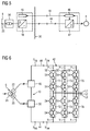
Figur 1 ist eine erste bekannte Variante einer Stromversorgungseinrichtung für Subsea-Anwendungen schematisch veranschaulicht. In dieserFigur 1 sind mit 2 ein Spannungszwischenkreis-Umrichter, mit 4 ein elektrischer Motor eines Antriebs, mit 6 ein Stromrichtertransformator und mit 8 ein speisendes Versorgungsnetz bezeichnet. Der Spannungszwischenkreis-Umrichter 2 weist einen netz- undlastseitigen Stromrichter 10 und 12 auf, die gleichspannungsseitig mittels eines Gleichspannungs-Zwischenkreises, der aus Übersichtlichkeitsgründen nicht explizit dargestellt ist, elektrisch miteinander verbunden sind. Der lastseitige Stromrichter, der vorzugsweise ein selbstgeführter Pulsstromrichter ist, ist mittels einesdreiphasigen Wechselstromkabels 14 mit demMotor 4 verknüpft. Außerdem weist dieserUmrichter 2 eineSignalelektronik 16 auf, die eingangsseitig mittels einerDatenleitung 18 mit Anschlüssen deselektrischen Motors 4 verbunden sein kann, deshalb ist diesesDatenkabel 18 mittels einer unterbrochenen Linie dargestellt, und ausgangsseitig mit Steueranschlüssen desselbstgeführten Pulsstromrichters 12 verbunden. AlsStromrichtertransformator 6 ist ein Transformator mit zweiSekundärwicklungen 20 und 22 vorgesehen, von denen dieSekundärwicklung 20 in Dreieck und dieSekundärwicklung 22 in Stern geschaltet sind. Da diePrimärwicklung 24 ebenfalls in Stern geschaltet ist, weist nur dieSekundärwicklung 20 zurPrimärwicklung 24 einen Verschiebungswinkel von 30° el. auf. DiePrimärwicklung 24 ist mit demspeisenden Netz 8, insbesondere mit einemEinpeisepunkt 26, elektrisch leitend verbunden. Alsnetzseitiger Stromrichter 10 ist eine Diodeneinspeisung vorgesehen, die 12-pulsig ausgeführt ist. Das heißt, dieseDiodeneinspeisung 10 weist zwei dreiphasige Diodenbrücken auf, die gleichspannungsseitig elektrisch in Reihe geschaltet sind. Durch die 12-pulsige Ausführungsform derDiodeneinspeisung 10 sind die Stromüberschwingungen imspeisenden Netz 8 gering. Diese Stromversorgungseinrichtung für Subsea-Anwendungen ist an Land bzw. auf einer Plattform auf dem Meer angeordnet. Der Übergang von Land bzw. Plattform zum Meer ist durch dieWellenlinien 30 angedeutet. Somit befindet sich nur der Antrieb, bestehend aus demMotor 4 und einer Pumpe bzw. einem Kompressor, auf dem Meeresboden. Vom Antrieb ist nur derMotor 4 näher dargestellt.
- In the
FIG. 1 a first known variant of a power supply device for subsea applications is illustrated schematically. In thisFIG. 1 2 is a voltage source inverter, 4 is an electric motor of a drive, 6 is a converter transformer, and 8 is a feeding supply network. The voltage intermediate-circuit converter 2 has a mains and load-side power converter motor 4 by means of a three-phase AC cable 14. In addition, thisinverter 2 has asignal electronics 16, which can be connected on the input side by means of adata line 18 to terminals of theelectric motor 4, therefore, thisdata cable 18 is shown by a broken line, and the output side connected to control terminals of the self-commutatedpulse converter 12. As aconverter transformer 6, a transformer with twosecondary windings secondary winding 20 are connected in a triangle and thesecondary winding 22 in star. Since theprimary winding 24 is also connected in star, only thesecondary winding 20 to theprimary winding 24 has a displacement angle of 30 ° el. On. Theprimary winding 24 is electrically connected to thefeeding network 8, in particular to afeed point 26. As a line-side converter 10, a diode feed is provided, which is carried out 12-pulse. That is, thisdiode feed 10 has two three-phase diode bridges, which are electrically connected in series on the DC side. Due to the 12-pulse embodiment of thediode feed 10, the current overshoots in thefeeding network 8 are low. This power supply for subsea applications is located on land or on a platform at sea. The transition from land or platform to the sea is indicated by thewavy lines 30. Thus, only the drive, consisting of themotor 4 and a pump or a compressor, located on the seabed. From the drive only theengine 4 is shown in more detail.
Da die kapazitive Ladeleistung des Wechselstromkabels 14 einen hohen Blindleistungsbedarf an den Spannungszwischenkreis-Umrichter 2 stellt, kann zwischen Umrichter 2 und Motor 4 nur eine begrenzte Distanz vorgesehen sein. Außerdem ist mit dieser Stromversorgungseinrichtung kein Mehrmotorenantrieb möglich. Jeder Motor 4 eines Antriebs muss mittels eines eigenen Wechselstromkabels 14 mit dem Spannungszwischenkreis-Umrichter 2 verbunden werden.Since the capacitive charging power of the
In der
Bei einer weiteren Variante der Stromversorgungseinrichtung eines drehzahlveränderbaren Antriebs auf Meeresgrund ist der Spannungszwischenkreis-Umrichter 2 mit netzseitigem Stromrichtertransformator 6 gemäß
Bei dieser Stromversorgungseinrichtung befindet sich nur noch der Transformator 36 an Land bzw. auf einer im Meer angeordneten Plattform. Der Spannungszwischenkreis-Umrichter 2 befindet sich nun am Motor 4 auf dem Meeresgrund, wobei dieser direkt am Motor 4 angebunden werden kann. Dadurch wird die Antriebs-Performance verbessert, wobei nun auch der Umrichter 2 verkapselt ausgeführt sein muss. Gegenüber der Variante der Stromversorgungseinrichtung gemäß
In der
Aus der Veröffentlichung "Valhall Re-Development Project, Power from Shore" von Sverre Gilje und Lars Carlsson, abgedruckt in "ENERGEX 2006", sowie aus Dokument
Der Erfindung liegt nun die Aufgabe zugrunde, die bekannte Stromversorgungseinrichtung derart weiterzubilden, dass der Abstand zwischen Einspeisepunkt an Land und Antrieb am Meeresgrund wesentlich größer wird.The invention is based on the object, the known power supply device such that the distance between the feed point to land and drive at the seabed is much larger.
Diese Aufgabe wird mit den kennzeichnenden Merkmalen des Anspruchs 1 erfindungsgemäß gelöst.This object is achieved with the characterizing features of claim 1 according to the invention.
Dadurch, dass als lastseitiger selbstgeführter Stromrichter der Stromversorgungseinrichtung ein Stromrichter mit verteilten Energiespeichern vorgesehen ist, dessen oberer und unterer Ventilzweig eines jeden Phasenmoduls wenigstens zwei elektrisch in Reihe geschaltete zweipolige Subsysteme aufweist, weist die Stromversorgungseinrichtung nach der Erfindung keine Energiespeicher im Gleichspannungszwischenkreis mehr auf, so dass nun das den netzseitigen Stromrichter und den lastseitigen Stromrichter der erfindungsgemäßen Stromversorgungseinrichtung elektrisch leitend verbindende Gleichstromkabel wesentlich größere Distanzen überbrücken kann. Dadurch kann der Stromrichter mit verteilten Energiespeichern der erfindungsgemäßen Stromversorgungseinrichtung am zu speisenden Motor am Meeresgrund und sein netzseitiger Stromrichter an Land angeordnet werden.Characterized in that a power converter with distributed energy storage is provided as load-side self-commutated power converter of the upper and lower valve branch of each phase module at least two electrically connected in series bipolar subsystems, the power supply device according to the invention no energy storage in the DC intermediate circuit more, so that now that the network-side converter and the load-side converter of the power supply device according to the invention electrically connecting DC cables can bridge much greater distances. As a result, the power converter with distributed energy stores of the power supply device according to the invention can be arranged on the motor to be fed on the seabed and its power converter on shore.
Durch den nicht notwendigerweise niederinduktiven Aufbau des Zwischenkreises und durch den fehlenden Zwischenkreiskondensator wird ein Zwischenkreiskurzschluss im Vergleich zu einem Spannungszwischenkreis-Umrichter mit einem Zwischenkreiskondensator sehr unwahrscheinlich. Dadurch müssen die Stromrichterventile des netzseitigen Stromrichters der erfindungsgemäβen Stromversorgungseinrichtung nicht mehr für einen durch einen niederohmigen Zwischenkreis-Kurzschluss hervorgerufenen Kurzschlussstrom ausgelegt werden. Außerdem kann die i2t-Anordnung dieser Stromrichterventile deutlich reduziert werden.Due to the not necessarily low-inductance design of the DC link and the missing DC link capacitor, a DC link short circuit becomes very unlikely compared to a DC link converter with a DC link capacitor. As a result, the converter valves of the line-side converter of the inventive power supply device no longer have to be designed for a short-circuit current caused by a low-resistance DC link short circuit. In addition, the i 2 t arrangement of these converter valves can be significantly reduced.
Durch die Verwendung eines Stromrichters mit einer Vielzahl von zweipoligen Subsystemen als lastseitigen Stromrichter der Stromversorgungseinrichtung kann der Spannungszwischenkreis-Umrichter zwischen Land und Meeresgrund aufgeteilt werden. Somit befindet sich nur noch der lastseitige Stromrichter mit verteilten Energiespeichern dieser Stromversorgungseinrichtung auf dem Meeresgrund. Da in Abhängigkeit der Anzahl der zweipoligen Subsysteme je Ventilzweig eines Phasenmoduls des lastseitigen Stromrichters mit verteilten Energiespeichern der Wert der Umrichter-Ausgangsspannung und damit der Motorspannung bestimmt wird, wird kein Transformator mehr am Meeresgrund benötigt.By using a power converter with a plurality of bipolar subsystems as a load-side power converter of the power supply device of the voltage source inverter can be divided between land and seabed. Thus, there is only the load-side converter with distributed energy storage of this power supply device on the seabed. As a function of the number of two-pole subsystems per valve branch of a phase module of the load-side converter with distributed energy storage, the value of the converter output voltage and thus the motor voltage is determined, no transformer is needed at the seabed.
Außerdem können durch die feingestufte Ausgangsspannungsform des lastseitigen Stromrichters mit verteilten Energiespeichern der erfindungsgemäßen Stromversorgungseinrichtung unter Wasser taugliche Motoren mit verminderten Anforderungen an die Wicklungsisolation verwendet werden. Da unabhängig von der Verwendung eines Transformators trotzdem eine hohe Motorspannung eingestellt werden kann, können Verbindungsleitungen und Durchführungen zum Motor für kleinere Ströme ausgelegt werden. Außerdem können dadurch bei höheren Leistungen Motoren mit mehreren Wicklungssystemen vermieden werden.In addition, can be used by the finely graded output voltage form of the load-side power converter with distributed energy storage devices of the power supply device according to the invention submerged motors with reduced requirements for the winding insulation. Since a high motor voltage can still be set regardless of the use of a transformer, connecting lines and feedthroughs to the motor can be designed for smaller currents. In addition, it can be avoided at higher power motors with multiple winding systems.
Da der lastseitige Stromrichter mit verteilten Energiespeichern der Stromversorgungseinrichtung pro Ventilzweig nur aus einer Anzahl elektrisch in Reihe geschalteter zweipoliger Subsysteme besteht, kann durch Hinzufügen von redundanten zweipoligen Subsysteme die Verfügbarkeit der Stromversorgungseinrichtung wesentlich erhöht werden.Since the load-side converter with distributed energy stores of the power supply device per valve branch only consists of a number of electrically connected in series bipolar subsystems, the availability of the power supply device can be substantially increased by adding redundant bipolar subsystems.
Neben dem netzseitigen Stromrichter der erfindungsgemäßen Stromversorgungseinrichtung wird auch eine Signalelektronik des lastseitigen auf Meeresgrund angeordneten Stromrichters mit verteilten Energiespeichern an Land angeordnet. Diese Signalelektronik ist mittels eines Datenkabels signaltechnisch mit Steuereingängen des lastseitigen Stromrichters mit verteilten Energiespeichern am Meeresgrund verbunden. Somit sind wesentliche Bauteile der erfindungsgemäßen Stromversorgungseinrichtung an Land bzw. auf einer Plattform untergebracht, so dass sich der Aufwand für die Kapselung der Bauteile der erfindungsgemäßen Stromversorgungseinrichtung wesentlich verringert.In addition to the network-side power converter of the power supply device according to the invention also signal electronics of the load-side arranged on the seabed power converter with distributed energy storage on land is arranged. This signal electronics is connected by means of a data cable signal technology with control inputs of the load-side converter with distributed energy storage on the seabed. Thus, essential components of the power supply device according to the invention are housed on land or on a platform, so that the cost of encapsulating the components of the power supply device according to the invention substantially reduced.
Bei einer vorteilhaften Ausführungsform der Stromversorgungseinrichtung nach der Erfindung ist der netzseitige ungesteuerte Stromrichter mittels des Gleichstromkabels mit einer auf Meeresgrund angeordneten Gleichspannungs-Sammelschiene elektrisch leitend verbunden. An dieser Gleichspannungs-Sammelschiene können eine Vielzahl von lastseitigen Stromrichtern mit verteilten Energiespeichern jeweils mit einem ausgangsseitigen Motor eines drehzahlveränderbaren Antriebs angeschlossen werden. Dadurch kann eine Stromversorgungseinrichtung nach der Erfindung kostengünstig für einen Mehrmotorenantrieb erstellt werden.In an advantageous embodiment of the power supply device according to the invention, the network-side uncontrolled power converter by means of the DC cable with a arranged on seabed DC busbar is electrically conductively connected. At this DC bus, a plurality of load-side converters with distributed energy storage can be connected in each case with an output-side motor of a variable speed drive. Thereby, a power supply device according to the invention can be inexpensively created for a multi-motor drive.
Weitere vorteilhafte Ausführungsformen der erfindungsgemäßen Stromversorgungseinrichtung sind den Ansprüchen 3 bis 11 entnehmbar.Further advantageous embodiments of the power supply device according to the invention are the
Zur weiteren Erläuterung der Erfindung wird auf die Zeichnung Bezug genommen, in der mehrere Ausführungsformen einer erfindungsgemäßen Stromversorgungseinrichtung schematisch veranschaulicht sind.
- FIG 1-4
- zeigen bekannte Varianten einer Stromversorgungseinrichtung für drehzahlveränderbare Antriebe für Subsea-Anwendungen, die
- FIG 5
- zeigt eine erste Variante einer Stromversorgungseinrichtung nach der Erfindung, die
- FIG 6
- zeigt ein Blockschaltbild einer vorteilhaften Ausführungsform einer Stromversorgungseinrichtung nach der Erfindung, in den
- FIG 7, 8
- sind Ausführungsformen jeweils eines zweipoligen Subsystems des lastseitigen Stromrichters der Stromversorgungseinrichtung nach
Figur 6 , und in der - FIG 9
- ist eine zweite Variante einer Stromversorgungseinrichtung nach der Erfindung schematisch dargestellt.
- 1-4
- show known variants of a power supply device for variable speed drives for subsea applications, the
- FIG. 5
- shows a first variant of a power supply device according to the invention, which
- FIG. 6
- shows a block diagram of an advantageous embodiment of a power supply device according to the invention, in which
- 7, 8
- Embodiments are each a bipolar subsystem of the load-side converter of the power supply device according to
FIG. 6 , and in the - FIG. 9
- a second variant of a power supply device according to the invention is shown schematically.
In der
In der
In der dargestellten Ausführungsform weist jeder Ventilzweig vier zweipolige Subsysteme 54 auf. Die zweipoligen Subsysteme 54 sind elektrisch in Reihe geschaltet. Ausführungsbeispiele dieser zweipoligen Subsysteme 54 sind in den
In der
In der Ausführungsform des Subsystems 54 gemäß
Gemäß der eingangs genannten Veröffentlichung mit dem Titel "Modulares Stromrichterkonzept für Netzkupplungsanwendung bei hohen Spannungen" kann das zweipolige Subsystem 54 drei Schaltzustände einnehmen. Im Schaltzustand I ist der abschaltbare Halbleiterschalter 56 eingeschaltet und der abschaltbare Halbleiterschalter 58 ausgeschaltet. In diesem Schaltzustand I ist die Klemmenspannung UX21 des zweipoligen Subsystems 54 gleich Null. Im Schaltzustand II sind der abschaltbare Halbleiterschalter 56 ausgeschaltet und der abschaltbare Halbleiterschalter 58 eingeschaltet. In diesem Schaltzustand II ist die Klemmenspannung UX21 des zweipoligen Subsystems 54 gleich der Spannung UC am Speicherkondensator 64. Im normalen, störungsfreien Betrieb werden nur diese beiden Schaltzustände I und II genutzt. Im Schaltzustand III sind beide abschaltbare Halbleiterschalter 56 und 58 ausgeschaltet.According to the above-cited publication entitled "Modular Converter Concept for High Voltage Network Coupling Application", the
In der
Mit dieser erfindungsgemäßen Stromversorgungseinrichtung können drehzahlveränderbare Antriebe von Subsea-Anwendungen, beispielsweise Öl- und Gasförderanlagen, mit Energie aus einem speisenden Versorgungsnetz versorgt werden, wobei der Abstand zwischen der Einspeisung an Land und dem Antrieb am Meeresgrund mehrere hundert Kilometer bei Meerestiefen von mehreren Kilometern betragen kann.With this power supply device according to the invention, variable-speed drives of subsea applications, for example oil and gas conveyors, can be supplied with energy from a feeding supply network, wherein the distance between the feed on land and the drive on the seabed can be several hundred kilometers at sea depths of several kilometers ,
Claims (11)
- Power supply device for a variable rotation speed drive which is arranged on the seabed, wherein this power supply device has a power converter (10, 12) on the power supply system and load sides, which are electrically conductively connected to one another on the DC voltage side by means of a direct-current cable (44) and whose power converter (10) on the power supply system side is connected to a feeding power supply system (8) on land,
characterized in that an uncontrolled power converter (10) is provided on the power supply system side and a power converter (42) with distributed energy stores is provided on the load side, in that each phase module (52) of the power converter (42) with distributed energy stores has an upper and a lower valve branch (T1, T3, T5; T2, T4, T6), which has at least two series-connected, two-pole subsystems (54), in that the power converter (42) with distributed energy stores is arranged on the seabed in the immediate vicinity of the variable rotation speed drive, and in that signal electronics (16) of the power converter (42) with distributed energy stores are arranged on land. - Power supply device according to Claim 1,
characterized in that the uncontrolled power converter (10) on the power supply system side is electrically conductively connected by means of the direct-current cable (44) to a DC voltage busbar (66) which is arranged on the seabed, to which DC voltage busbar (66) at least one self-commutated power converter (42), on the load side, is connected, with a variable rotation speed drive on the AC voltage side. - Power supply device according to Claim 1 or 2,
characterized in that the uncontrolled power converter (10) on the power supply system side is arranged on a platform which is arranged at sea. - Power supply device according to one of the abovementioned claims,
characterized in that a diode rectifier is provided as the uncontrolled power converter (10) on the power supply system side. - Power supply device according to Claim 4,
characterized in that the diode rectifier is a 12-pulse rectifier. - Power supply device according to Claim 4,
characterized in that the diode rectifier is an 18-pulse rectifier. - Power supply device according to Claim 4,
characterized in that the diode rectifier is a 24-pulse rectifier. - Power supply device according to one of the abovementioned claims,
characterized in that a two-pole subsystem (54) has an energy storage capacitor (64) and two semiconductor switches (56, 58), which can be turned off and are electrically connected in series, wherein this series circuit is connected electrically in parallel with the energy storage capacitor (64), wherein a junction point between the two semiconductor switches (56, 58) which can be turned off forms a first connecting terminal (X2, X1) of the two-pole subsystem (54), and wherein one pole of the energy storage capacitor (64) forms a second connecting terminal (X1, X2) of this two-pole subsystem (54). - Power supply device according to Claim 8,
characterized in that an insulated gate bipolar transistor is provided as the semiconductor switch (56, 58) which can be turned off. - Power supply device according to one of the abovementioned claims,
characterized in that the variable rotation speed drive has an electric motor with a pump on the rotor side. - Power supply device according to one of Claims 1 to 9,
characterized in that the variable rotation speed drive has an electric motor with a compressor on the rotor side.
Applications Claiming Priority (2)
| Application Number | Priority Date | Filing Date | Title |
|---|---|---|---|
| DE102008022618A DE102008022618A1 (en) | 2008-05-07 | 2008-05-07 | Power supply means |
| PCT/EP2009/053654 WO2009135730A1 (en) | 2008-05-07 | 2009-03-27 | Power supply device |
Publications (2)
| Publication Number | Publication Date |
|---|---|
| EP2274825A1 EP2274825A1 (en) | 2011-01-19 |
| EP2274825B1 true EP2274825B1 (en) | 2016-08-10 |
Family
ID=40875153
Family Applications (1)
| Application Number | Title | Priority Date | Filing Date |
|---|---|---|---|
| EP09741948.5A Active EP2274825B1 (en) | 2008-05-07 | 2009-03-27 | Power supply device |
Country Status (10)
| Country | Link |
|---|---|
| US (1) | US8476854B2 (en) |
| EP (1) | EP2274825B1 (en) |
| JP (1) | JP5506784B2 (en) |
| CN (1) | CN102017385B (en) |
| BR (1) | BRPI0912423B1 (en) |
| CY (1) | CY1118133T1 (en) |
| DE (1) | DE102008022618A1 (en) |
| DK (1) | DK2274825T3 (en) |
| RU (1) | RU2479914C2 (en) |
| WO (1) | WO2009135730A1 (en) |
Families Citing this family (41)
| Publication number | Priority date | Publication date | Assignee | Title |
|---|---|---|---|---|
| DE102005045091B4 (en) | 2005-09-21 | 2007-08-30 | Siemens Ag | Control method for redundancy use in case of failure of a multiphase power converter with distributed energy storage |
| US8692408B2 (en) * | 2008-12-03 | 2014-04-08 | General Electric Company | Modular stacked subsea power system architectures |
| JP5176006B2 (en) * | 2009-10-06 | 2013-04-03 | エー ビー ビー リサーチ リミテッド | Voltage type converter |
| NO332768B1 (en) * | 2009-12-16 | 2013-01-14 | Smartmotor As | System for operation of elongated electric machines |
| JP5931065B2 (en) | 2010-08-04 | 2016-06-08 | ベンショウ・インコーポレイテッド | Modular multi-voltage output converter device connected to current source power supply |
| JP5964306B2 (en) | 2010-09-09 | 2016-08-03 | ベンショウ・インコーポレイテッド | Apparatus and method for controlling a modular multi-voltage output converter device |
| MY185123A (en) * | 2010-09-13 | 2021-04-30 | Aker Solutions As | Stable subsea electric power transmission to run subsea high speed motors |
| WO2012040257A1 (en) | 2010-09-21 | 2012-03-29 | Curtiss-Wright Electro-Mechanical Corporation | Two terminal multilevel converter |
| US9450412B2 (en) * | 2010-12-22 | 2016-09-20 | General Electric Company | Method and system for control power in remote DC power systems |
| US8624431B2 (en) * | 2011-02-26 | 2014-01-07 | General Electric Company | System and method for power sharing of front-end converters without communication link in a modular-stacked DC transmission system |
| BR112013022224B1 (en) * | 2011-03-02 | 2020-02-11 | Abb Schweiz Ag | SYSTEM FOR THE OPERATION OF AN ELECTRICAL MACHINE AND METHOD FOR THE PROTECTION OF AN OPERATION CONTROL UNIT |
| DE102011006987A1 (en) | 2011-04-07 | 2012-10-11 | Siemens Aktiengesellschaft | Modular power converter cabinet system |
| AU2011250865A1 (en) * | 2011-08-15 | 2013-03-07 | Saminco Inc. | DC trailing cable system for tethered mining vehicles |
| GB2493938B (en) * | 2011-08-23 | 2014-08-13 | Framo Eng As | Double motor pump with variable speed drive |
| EP2626994B1 (en) * | 2012-02-08 | 2019-04-03 | GE Oil & Gas UK Limited | Supplying electrical power to subsea equipment |
| WO2013132103A1 (en) * | 2012-03-09 | 2013-09-12 | Abb Technology Ag | Method for using an electrical unit |
| MX345133B (en) | 2012-03-09 | 2017-01-18 | Benshaw Inc | M2lc system and method for controlling same. |
| US20150288287A1 (en) * | 2012-09-21 | 2015-10-08 | Aukland Uniservices Limited | Modular multi-level converters |
| DK2713468T3 (en) * | 2012-09-28 | 2019-11-04 | Ge Energy Power Conversion Technology Ltd | Electrical energy transfer systems |
| EP2762347A1 (en) | 2013-01-31 | 2014-08-06 | Siemens Aktiengesellschaft | Modular high frequency converter and method for operating the same |
| US9853562B2 (en) * | 2013-02-28 | 2017-12-26 | Siemens Aktiengesellschaft | Converter station with diode rectifier |
| JP2016510203A (en) * | 2013-02-28 | 2016-04-04 | シーメンス アクチエンゲゼルシヤフトSiemens Aktiengesellschaft | Converter station with diode rectifier |
| EP2773032A1 (en) * | 2013-03-01 | 2014-09-03 | GE Energy Power Conversion Technology Ltd | Current source converter with gate turn off semiconductor elements and a special commutation mode |
| US9859806B2 (en) * | 2014-03-14 | 2018-01-02 | Abb Research Ltd. | Method and apparatus for obtaining electricity from offshore wind turbines |
| GB2540506B (en) | 2014-05-07 | 2021-09-08 | Aker Solutions As | Power supply assembly and associated method |
| EP2961021A1 (en) * | 2014-06-27 | 2015-12-30 | Siemens Aktiengesellschaft | Subsea power distribution system and method |
| NO337348B1 (en) * | 2014-08-18 | 2016-03-21 | Aker Subsea As | VARIETY SPEED OPERATING VARIABLE SPEED FOR LARGE PUMPS AND COMPRESSORS. |
| EP2996238A1 (en) * | 2014-09-09 | 2016-03-16 | ABB Technology Ltd | Modular subsea converter |
| US20160215769A1 (en) * | 2015-01-27 | 2016-07-28 | Baker Hughes Incorporated | Systems and Methods for Providing Power to Well Equipment |
| EP3131377A1 (en) | 2015-08-14 | 2017-02-15 | Siemens Aktiengesellschaft | Phase module for a power converter |
| GB2545455A (en) | 2015-12-17 | 2017-06-21 | General Electric Technology Gmbh | Power supply apparatus |
| CN105807664A (en) * | 2016-04-25 | 2016-07-27 | 浙江大学 | Underwater splitter based on high-low level digital signal control |
| DE102016209983A1 (en) * | 2016-06-07 | 2017-12-07 | Leybold Gmbh | Apparatus and method for driving a vacuum pump |
| US10153640B2 (en) * | 2016-11-30 | 2018-12-11 | State Grid Jiangsu Electric Power Research Institute | Unified power flow controller and control method thereof |
| EP3407447A1 (en) * | 2017-05-24 | 2018-11-28 | Siemens Aktiengesellschaft | Highly redundant direct current network |
| WO2020152813A1 (en) * | 2019-01-24 | 2020-07-30 | 株式会社日立産機システム | Power conversion system |
| US20210320578A1 (en) | 2020-04-08 | 2021-10-14 | Halliburton Energy Services, Inc. | Axial Flux Submersible Electric Motor |
| CN113765426A (en) | 2020-06-01 | 2021-12-07 | 台达电子企业管理(上海)有限公司 | Control method and control system of modular multilevel converter and power transmission system |
| CN113765425A (en) | 2020-06-01 | 2021-12-07 | 台达电子企业管理(上海)有限公司 | Control method and control system of modular multilevel converter and power transmission system |
| CN111799661B (en) * | 2020-06-04 | 2022-05-20 | 许继集团有限公司 | Converter station of modular offshore flexible direct current transmission system |
| US11677264B2 (en) * | 2020-11-09 | 2023-06-13 | Electronic Power Design, Inc. | System and method for a backup power supply |
Family Cites Families (22)
| Publication number | Priority date | Publication date | Assignee | Title |
|---|---|---|---|---|
| JPH0677710B2 (en) * | 1986-05-15 | 1994-10-05 | 兵神装備株式会社 | Metering device |
| US5050058A (en) * | 1990-08-14 | 1991-09-17 | La Corporation De L'ecole Polytechnique | Family of power converters using rectifier transformers connected in series on the primary side |
| US5804953A (en) * | 1995-08-03 | 1998-09-08 | Atlas Energy Systems, Inc. | Power converter for converting AC shore power to shipboard use |
| SE524384C2 (en) * | 1997-03-24 | 2004-08-03 | Abb Ab | Electric power transmission system |
| RU2137945C1 (en) | 1997-04-15 | 1999-09-20 | Вячеслав Александрович Чванов | Electric submersible pumping unit |
| JP3290947B2 (en) * | 1998-03-12 | 2002-06-10 | 株式会社東芝 | Power converter |
| US6519169B1 (en) * | 1999-03-29 | 2003-02-11 | Abb Ab | Multiphase inverter with series of connected phase legs |
| JP2002142365A (en) * | 2000-11-06 | 2002-05-17 | Toshiba Corp | Dc transmission facility |
| DE10103031B4 (en) * | 2001-01-24 | 2011-12-01 | Siemens Ag | Converter circuit with distributed energy storage and method for controlling such a converter circuit |
| GB2382600B (en) * | 2001-12-03 | 2005-05-11 | Abb Offshore Systems Ltd | Transmitting power to an underwater hydrocarbon production system |
| RU28743U1 (en) | 2002-10-04 | 2003-04-10 | Федеральное государственное унитарное предприятие "НПП ВНИИЭМ" | Electric submersible installation |
| JP2004254456A (en) * | 2003-02-21 | 2004-09-09 | Sumitomo Electric Ind Ltd | Wind power generation system |
| EP1385259A3 (en) * | 2003-09-24 | 2004-04-28 | ABB Technology AG | A system for high power drives |
| JP2005307784A (en) * | 2004-04-19 | 2005-11-04 | Kawamoto Densan Kk | Control device for submerged pump |
| DE102004033578A1 (en) * | 2004-07-05 | 2006-02-02 | Siemens Ag | Device for high voltage light current transmission |
| US7969755B2 (en) * | 2005-09-09 | 2011-06-28 | Siemens Aktiengesellschaft | Apparatus for electrical power transmission |
| CA2622089A1 (en) * | 2005-09-09 | 2007-03-15 | Siemens Aktiengesellschaft | Apparatus for electrical power transmission |
| DE102005045090B4 (en) * | 2005-09-21 | 2007-08-30 | Siemens Ag | Method for controlling a multiphase power converter with distributed energy storage |
| US8251614B2 (en) * | 2005-12-19 | 2012-08-28 | Siemens Aktiengesellschaft | Electrical power system for a subsea system |
| MY140418A (en) | 2006-01-27 | 2009-12-31 | Alpha Perisai Sdn Bhd | Electrical power transmission system |
| DE102006042038B3 (en) * | 2006-09-07 | 2008-02-07 | Siemens Ag | Field-oriented driven inverter-fed three-phase alternating current motor torque limiting method, involves generating impulse resetting signal when threshold value exceeds or torque-forming current components are unequal |
| US20080203734A1 (en) * | 2007-02-22 | 2008-08-28 | Mark Francis Grimes | Wellbore rig generator engine power control |
-
2008
- 2008-05-07 DE DE102008022618A patent/DE102008022618A1/en not_active Ceased
-
2009
- 2009-03-27 JP JP2011507854A patent/JP5506784B2/en not_active Expired - Fee Related
- 2009-03-27 CN CN200980116471.6A patent/CN102017385B/en active Active
- 2009-03-27 EP EP09741948.5A patent/EP2274825B1/en active Active
- 2009-03-27 RU RU2010149958/07A patent/RU2479914C2/en not_active IP Right Cessation
- 2009-03-27 WO PCT/EP2009/053654 patent/WO2009135730A1/en active Application Filing
- 2009-03-27 DK DK09741948.5T patent/DK2274825T3/en active
- 2009-03-27 BR BRPI0912423-3A patent/BRPI0912423B1/en not_active IP Right Cessation
- 2009-03-27 US US12/991,277 patent/US8476854B2/en active Active
-
2016
- 2016-10-21 CY CY20161101062T patent/CY1118133T1/en unknown
Also Published As
| Publication number | Publication date |
|---|---|
| RU2010149958A (en) | 2012-06-20 |
| EP2274825A1 (en) | 2011-01-19 |
| CY1118133T1 (en) | 2017-06-28 |
| DK2274825T3 (en) | 2016-11-21 |
| JP5506784B2 (en) | 2014-05-28 |
| US20110089873A1 (en) | 2011-04-21 |
| RU2479914C2 (en) | 2013-04-20 |
| DE102008022618A1 (en) | 2009-12-31 |
| BRPI0912423B1 (en) | 2019-02-12 |
| CN102017385B (en) | 2014-07-16 |
| CN102017385A (en) | 2011-04-13 |
| WO2009135730A1 (en) | 2009-11-12 |
| US8476854B2 (en) | 2013-07-02 |
| JP2011520412A (en) | 2011-07-14 |
| BRPI0912423A2 (en) | 2016-02-10 |
Similar Documents
| Publication | Publication Date | Title |
|---|---|---|
| EP2274825B1 (en) | Power supply device | |
| EP2241001B1 (en) | Converter | |
| EP2283233B1 (en) | Wind power plant and wind farm comprising plurality of wind power plants | |
| EP2681834B1 (en) | Modular converter cabinet system | |
| EP1311058B1 (en) | Frequency power converter | |
| EP3005543B1 (en) | Modular multilevel dc/dc converter for hvdc applications | |
| EP2088668A2 (en) | Static convertor | |
| EP3109966B1 (en) | Wind farm connection with diode rectifier | |
| WO2003090331A2 (en) | Power supply with a direct converter | |
| EP2107672A1 (en) | Three-phase inverter without connection between the neutral conductor of the grid and the mid-point of the intermediate circuit | |
| EP2408081A1 (en) | Modular multi-level converter | |
| WO2014001079A1 (en) | Power converter and operating method for converting voltages | |
| EP2928060A1 (en) | Modular frequency converter circuit with submodules having different switching capacities | |
| WO2019007502A1 (en) | Multilevel power converter | |
| EP3363091B1 (en) | Device and method for controlling a load flow in an alternating-voltage network | |
| EP3180844B1 (en) | Power converter arrangement with short-circuit unit and method for separating an ac voltage line | |
| EP3331118B1 (en) | System for transmitting electric power | |
| DE102015008369A1 (en) | Circuit arrangement for the bidirectional coupling of a DC voltage system with a plurality of AC systems and method for controlling such a circuit arrangement | |
| EP4264815A1 (en) | Converter for alternating current systems | |
| WO2018059664A1 (en) | Arrangement and method for transmitting electrical power | |
| DE102010010781A1 (en) | Inverter and single electric machine arrangement, has bridge circuit added to electronic circuit that raises direct voltage at direct voltage terminals of bridge during switching off of semiconductor switches of bridge for short period |
Legal Events
| Date | Code | Title | Description |
|---|---|---|---|
| PUAI | Public reference made under article 153(3) epc to a published international application that has entered the european phase |
Free format text: ORIGINAL CODE: 0009012 |
|
| 17P | Request for examination filed |
Effective date: 20101013 |
|
| AK | Designated contracting states |
Kind code of ref document: A1 Designated state(s): AT BE BG CH CY CZ DE DK EE ES FI FR GB GR HR HU IE IS IT LI LT LU LV MC MK MT NL NO PL PT RO SE SI SK TR |
|
| AX | Request for extension of the european patent |
Extension state: AL BA RS |
|
| DAX | Request for extension of the european patent (deleted) | ||
| RAP1 | Party data changed (applicant data changed or rights of an application transferred) |
Owner name: SIEMENS AKTIENGESELLSCHAFT |
|
| GRAP | Despatch of communication of intention to grant a patent |
Free format text: ORIGINAL CODE: EPIDOSNIGR1 |
|
| INTG | Intention to grant announced |
Effective date: 20160226 |
|
| GRAS | Grant fee paid |
Free format text: ORIGINAL CODE: EPIDOSNIGR3 |
|
| GRAA | (expected) grant |
Free format text: ORIGINAL CODE: 0009210 |
|
| AK | Designated contracting states |
Kind code of ref document: B1 Designated state(s): AT BE BG CH CY CZ DE DK EE ES FI FR GB GR HR HU IE IS IT LI LT LU LV MC MK MT NL NO PL PT RO SE SI SK TR |
|
| REG | Reference to a national code |
Ref country code: GB Ref legal event code: FG4D Free format text: NOT ENGLISH |
|
| REG | Reference to a national code |
Ref country code: CH Ref legal event code: EP Ref country code: AT Ref legal event code: REF Ref document number: 819836 Country of ref document: AT Kind code of ref document: T Effective date: 20160815 |
|
| REG | Reference to a national code |
Ref country code: IE Ref legal event code: FG4D Free format text: LANGUAGE OF EP DOCUMENT: GERMAN |
|
| REG | Reference to a national code |
Ref country code: DE Ref legal event code: R096 Ref document number: 502009012934 Country of ref document: DE |
|
| REG | Reference to a national code |
Ref country code: CH Ref legal event code: NV Representative=s name: SIEMENS SCHWEIZ AG, CH |
|
| REG | Reference to a national code |
Ref country code: SE Ref legal event code: TRGR |
|
| REG | Reference to a national code |
Ref country code: NL Ref legal event code: FP |
|
| REG | Reference to a national code |
Ref country code: DK Ref legal event code: T3 Effective date: 20161115 |
|
| REG | Reference to a national code |
Ref country code: LT Ref legal event code: MG4D Ref country code: NO Ref legal event code: T2 Effective date: 20160810 |
|
| PG25 | Lapsed in a contracting state [announced via postgrant information from national office to epo] |
Ref country code: HR Free format text: LAPSE BECAUSE OF FAILURE TO SUBMIT A TRANSLATION OF THE DESCRIPTION OR TO PAY THE FEE WITHIN THE PRESCRIBED TIME-LIMIT Effective date: 20160810 Ref country code: LT Free format text: LAPSE BECAUSE OF FAILURE TO SUBMIT A TRANSLATION OF THE DESCRIPTION OR TO PAY THE FEE WITHIN THE PRESCRIBED TIME-LIMIT Effective date: 20160810 |
|
| PG25 | Lapsed in a contracting state [announced via postgrant information from national office to epo] |
Ref country code: LV Free format text: LAPSE BECAUSE OF FAILURE TO SUBMIT A TRANSLATION OF THE DESCRIPTION OR TO PAY THE FEE WITHIN THE PRESCRIBED TIME-LIMIT Effective date: 20160810 Ref country code: PT Free format text: LAPSE BECAUSE OF FAILURE TO SUBMIT A TRANSLATION OF THE DESCRIPTION OR TO PAY THE FEE WITHIN THE PRESCRIBED TIME-LIMIT Effective date: 20161212 Ref country code: PL Free format text: LAPSE BECAUSE OF FAILURE TO SUBMIT A TRANSLATION OF THE DESCRIPTION OR TO PAY THE FEE WITHIN THE PRESCRIBED TIME-LIMIT Effective date: 20160810 Ref country code: GR Free format text: LAPSE BECAUSE OF FAILURE TO SUBMIT A TRANSLATION OF THE DESCRIPTION OR TO PAY THE FEE WITHIN THE PRESCRIBED TIME-LIMIT Effective date: 20161111 Ref country code: ES Free format text: LAPSE BECAUSE OF FAILURE TO SUBMIT A TRANSLATION OF THE DESCRIPTION OR TO PAY THE FEE WITHIN THE PRESCRIBED TIME-LIMIT Effective date: 20160810 |
|
| REG | Reference to a national code |
Ref country code: FR Ref legal event code: PLFP Year of fee payment: 9 |
|
| PG25 | Lapsed in a contracting state [announced via postgrant information from national office to epo] |
Ref country code: RO Free format text: LAPSE BECAUSE OF FAILURE TO SUBMIT A TRANSLATION OF THE DESCRIPTION OR TO PAY THE FEE WITHIN THE PRESCRIBED TIME-LIMIT Effective date: 20160810 Ref country code: EE Free format text: LAPSE BECAUSE OF FAILURE TO SUBMIT A TRANSLATION OF THE DESCRIPTION OR TO PAY THE FEE WITHIN THE PRESCRIBED TIME-LIMIT Effective date: 20160810 |
|
| PGFP | Annual fee paid to national office [announced via postgrant information from national office to epo] |
Ref country code: FI Payment date: 20170313 Year of fee payment: 9 |
|
| REG | Reference to a national code |
Ref country code: DE Ref legal event code: R097 Ref document number: 502009012934 Country of ref document: DE |
|
| PG25 | Lapsed in a contracting state [announced via postgrant information from national office to epo] |
Ref country code: BG Free format text: LAPSE BECAUSE OF FAILURE TO SUBMIT A TRANSLATION OF THE DESCRIPTION OR TO PAY THE FEE WITHIN THE PRESCRIBED TIME-LIMIT Effective date: 20161110 Ref country code: SK Free format text: LAPSE BECAUSE OF FAILURE TO SUBMIT A TRANSLATION OF THE DESCRIPTION OR TO PAY THE FEE WITHIN THE PRESCRIBED TIME-LIMIT Effective date: 20160810 Ref country code: CZ Free format text: LAPSE BECAUSE OF FAILURE TO SUBMIT A TRANSLATION OF THE DESCRIPTION OR TO PAY THE FEE WITHIN THE PRESCRIBED TIME-LIMIT Effective date: 20160810 |
|
| PGFP | Annual fee paid to national office [announced via postgrant information from national office to epo] |
Ref country code: IS Payment date: 20170216 Year of fee payment: 9 Ref country code: IE Payment date: 20170323 Year of fee payment: 9 Ref country code: CY Payment date: 20170228 Year of fee payment: 9 Ref country code: DK Payment date: 20170321 Year of fee payment: 9 |
|
| PLBE | No opposition filed within time limit |
Free format text: ORIGINAL CODE: 0009261 |
|
| STAA | Information on the status of an ep patent application or granted ep patent |
Free format text: STATUS: NO OPPOSITION FILED WITHIN TIME LIMIT |
|
| PGFP | Annual fee paid to national office [announced via postgrant information from national office to epo] |
Ref country code: IT Payment date: 20170329 Year of fee payment: 9 Ref country code: TR Payment date: 20170314 Year of fee payment: 9 |
|
| 26N | No opposition filed |
Effective date: 20170511 |
|
| PG25 | Lapsed in a contracting state [announced via postgrant information from national office to epo] |
Ref country code: SI Free format text: LAPSE BECAUSE OF FAILURE TO SUBMIT A TRANSLATION OF THE DESCRIPTION OR TO PAY THE FEE WITHIN THE PRESCRIBED TIME-LIMIT Effective date: 20160810 |
|
| REG | Reference to a national code |
Ref country code: CH Ref legal event code: PCOW Free format text: NEW ADDRESS: WERNER-VON-SIEMENS-STRASSE 1, 80333 MUENCHEN (DE) |
|
| PG25 | Lapsed in a contracting state [announced via postgrant information from national office to epo] |
Ref country code: MC Free format text: LAPSE BECAUSE OF FAILURE TO SUBMIT A TRANSLATION OF THE DESCRIPTION OR TO PAY THE FEE WITHIN THE PRESCRIBED TIME-LIMIT Effective date: 20160810 |
|
| PG25 | Lapsed in a contracting state [announced via postgrant information from national office to epo] |
Ref country code: LU Free format text: LAPSE BECAUSE OF NON-PAYMENT OF DUE FEES Effective date: 20170327 |
|
| REG | Reference to a national code |
Ref country code: BE Ref legal event code: MM Effective date: 20170331 |
|
| REG | Reference to a national code |
Ref country code: FR Ref legal event code: PLFP Year of fee payment: 10 |
|
| REG | Reference to a national code |
Ref country code: AT Ref legal event code: MM01 Ref document number: 819836 Country of ref document: AT Kind code of ref document: T Effective date: 20170327 |
|
| PG25 | Lapsed in a contracting state [announced via postgrant information from national office to epo] |
Ref country code: BE Free format text: LAPSE BECAUSE OF NON-PAYMENT OF DUE FEES Effective date: 20170331 |
|
| PG25 | Lapsed in a contracting state [announced via postgrant information from national office to epo] |
Ref country code: AT Free format text: LAPSE BECAUSE OF NON-PAYMENT OF DUE FEES Effective date: 20170327 |
|
| PG25 | Lapsed in a contracting state [announced via postgrant information from national office to epo] |
Ref country code: MT Free format text: LAPSE BECAUSE OF FAILURE TO SUBMIT A TRANSLATION OF THE DESCRIPTION OR TO PAY THE FEE WITHIN THE PRESCRIBED TIME-LIMIT Effective date: 20160810 |
|
| REG | Reference to a national code |
Ref country code: DK Ref legal event code: EBP Effective date: 20180331 |
|
| PG25 | Lapsed in a contracting state [announced via postgrant information from national office to epo] |
Ref country code: CY Free format text: LAPSE BECAUSE OF NON-PAYMENT OF DUE FEES Effective date: 20180327 Ref country code: FI Free format text: LAPSE BECAUSE OF NON-PAYMENT OF DUE FEES Effective date: 20180327 |
|
| REG | Reference to a national code |
Ref country code: IE Ref legal event code: MM4A |
|
| PG25 | Lapsed in a contracting state [announced via postgrant information from national office to epo] |
Ref country code: IE Free format text: LAPSE BECAUSE OF NON-PAYMENT OF DUE FEES Effective date: 20180327 Ref country code: IS Free format text: LAPSE BECAUSE OF FAILURE TO SUBMIT A TRANSLATION OF THE DESCRIPTION OR TO PAY THE FEE WITHIN THE PRESCRIBED TIME-LIMIT Effective date: 20181012 |
|
| PG25 | Lapsed in a contracting state [announced via postgrant information from national office to epo] |
Ref country code: IT Free format text: LAPSE BECAUSE OF NON-PAYMENT OF DUE FEES Effective date: 20180327 |
|
| PG25 | Lapsed in a contracting state [announced via postgrant information from national office to epo] |
Ref country code: DK Free format text: LAPSE BECAUSE OF NON-PAYMENT OF DUE FEES Effective date: 20180331 |
|
| PG25 | Lapsed in a contracting state [announced via postgrant information from national office to epo] |
Ref country code: HU Free format text: LAPSE BECAUSE OF FAILURE TO SUBMIT A TRANSLATION OF THE DESCRIPTION OR TO PAY THE FEE WITHIN THE PRESCRIBED TIME-LIMIT; INVALID AB INITIO Effective date: 20090327 |
|
| PG25 | Lapsed in a contracting state [announced via postgrant information from national office to epo] |
Ref country code: MK Free format text: LAPSE BECAUSE OF FAILURE TO SUBMIT A TRANSLATION OF THE DESCRIPTION OR TO PAY THE FEE WITHIN THE PRESCRIBED TIME-LIMIT Effective date: 20160810 |
|
| PGFP | Annual fee paid to national office [announced via postgrant information from national office to epo] |
Ref country code: NL Payment date: 20200311 Year of fee payment: 12 Ref country code: SE Payment date: 20200317 Year of fee payment: 12 |
|
| PGFP | Annual fee paid to national office [announced via postgrant information from national office to epo] |
Ref country code: CH Payment date: 20200602 Year of fee payment: 12 |
|
| REG | Reference to a national code |
Ref country code: GB Ref legal event code: 732E Free format text: REGISTERED BETWEEN 20210819 AND 20210825 |
|
| REG | Reference to a national code |
Ref country code: CH Ref legal event code: PL |
|
| REG | Reference to a national code |
Ref country code: NL Ref legal event code: MM Effective date: 20210401 |
|
| PG25 | Lapsed in a contracting state [announced via postgrant information from national office to epo] |
Ref country code: NL Free format text: LAPSE BECAUSE OF NON-PAYMENT OF DUE FEES Effective date: 20210401 Ref country code: CH Free format text: LAPSE BECAUSE OF NON-PAYMENT OF DUE FEES Effective date: 20210331 Ref country code: LI Free format text: LAPSE BECAUSE OF NON-PAYMENT OF DUE FEES Effective date: 20210331 Ref country code: SE Free format text: LAPSE BECAUSE OF NON-PAYMENT OF DUE FEES Effective date: 20210328 |
|
| PG25 | Lapsed in a contracting state [announced via postgrant information from national office to epo] |
Ref country code: TR Free format text: LAPSE BECAUSE OF NON-PAYMENT OF DUE FEES Effective date: 20180327 |
|
| PGFP | Annual fee paid to national office [announced via postgrant information from national office to epo] |
Ref country code: NO Payment date: 20230308 Year of fee payment: 15 Ref country code: FR Payment date: 20230317 Year of fee payment: 15 |
|
| PGFP | Annual fee paid to national office [announced via postgrant information from national office to epo] |
Ref country code: GB Payment date: 20230330 Year of fee payment: 15 |
|
| PGFP | Annual fee paid to national office [announced via postgrant information from national office to epo] |
Ref country code: DE Payment date: 20230331 Year of fee payment: 15 |
|
| REG | Reference to a national code |
Ref country code: DE Ref legal event code: R081 Ref document number: 502009012934 Country of ref document: DE Owner name: INNOMOTICS GMBH, DE Free format text: FORMER OWNER: SIEMENS AKTIENGESELLSCHAFT, 80333 MUENCHEN, DE |
|
| REG | Reference to a national code |
Ref country code: NO Ref legal event code: CHAD Owner name: INNOMOTICS GMBH, DE |