EP2242345B1 - Method and apparatus for cooling electronic components - Google Patents
Method and apparatus for cooling electronic components Download PDFInfo
- Publication number
- EP2242345B1 EP2242345B1 EP10006953.3A EP10006953A EP2242345B1 EP 2242345 B1 EP2242345 B1 EP 2242345B1 EP 10006953 A EP10006953 A EP 10006953A EP 2242345 B1 EP2242345 B1 EP 2242345B1
- Authority
- EP
- European Patent Office
- Prior art keywords
- electronic components
- cooling
- liquid
- module
- assembly
- Prior art date
- Legal status (The legal status is an assumption and is not a legal conclusion. Google has not performed a legal analysis and makes no representation as to the accuracy of the status listed.)
- Expired - Lifetime
Links
- 238000001816 cooling Methods 0.000 title claims abstract description 79
- 238000000034 method Methods 0.000 title claims description 38
- 239000012530 fluid Substances 0.000 claims abstract description 29
- 239000007921 spray Substances 0.000 claims abstract description 28
- 239000000758 substrate Substances 0.000 claims abstract description 10
- 239000012809 cooling fluid Substances 0.000 claims abstract description 7
- 230000003750 conditioning effect Effects 0.000 claims abstract description 5
- 239000007788 liquid Substances 0.000 claims description 42
- 239000007789 gas Substances 0.000 claims description 22
- IJGRMHOSHXDMSA-UHFFFAOYSA-N Atomic nitrogen Chemical compound N#N IJGRMHOSHXDMSA-UHFFFAOYSA-N 0.000 claims description 6
- 238000009835 boiling Methods 0.000 claims description 5
- 230000009972 noncorrosive effect Effects 0.000 claims description 5
- 229910052757 nitrogen Inorganic materials 0.000 claims description 3
- 238000010438 heat treatment Methods 0.000 claims description 2
- 239000011261 inert gas Substances 0.000 claims description 2
- XBTHILIDLBPRPM-UHFFFAOYSA-N 2,2',4,5-tetrachlorobiphenyl Chemical compound ClC1=CC=CC=C1C1=CC(Cl)=C(Cl)C=C1Cl XBTHILIDLBPRPM-UHFFFAOYSA-N 0.000 description 12
- 239000002826 coolant Substances 0.000 description 11
- 238000013461 design Methods 0.000 description 8
- 238000005516 engineering process Methods 0.000 description 8
- 238000004806 packaging method and process Methods 0.000 description 7
- 230000003134 recirculating effect Effects 0.000 description 7
- 238000013459 approach Methods 0.000 description 6
- 238000007726 management method Methods 0.000 description 6
- 238000004891 communication Methods 0.000 description 5
- 230000004907 flux Effects 0.000 description 5
- 230000006870 function Effects 0.000 description 5
- 238000012546 transfer Methods 0.000 description 5
- 208000031339 Split cord malformation Diseases 0.000 description 4
- 229910052782 aluminium Inorganic materials 0.000 description 4
- XAGFODPZIPBFFR-UHFFFAOYSA-N aluminium Chemical compound [Al] XAGFODPZIPBFFR-UHFFFAOYSA-N 0.000 description 4
- 230000006835 compression Effects 0.000 description 4
- 238000007906 compression Methods 0.000 description 4
- 230000007613 environmental effect Effects 0.000 description 4
- 238000004645 scanning capacitance microscopy Methods 0.000 description 4
- 238000013068 supply chain management Methods 0.000 description 4
- XLYOFNOQVPJJNP-UHFFFAOYSA-N water Substances O XLYOFNOQVPJJNP-UHFFFAOYSA-N 0.000 description 4
- RYGMFSIKBFXOCR-UHFFFAOYSA-N Copper Chemical compound [Cu] RYGMFSIKBFXOCR-UHFFFAOYSA-N 0.000 description 3
- 102100032467 Transmembrane protease serine 13 Human genes 0.000 description 3
- 238000000889 atomisation Methods 0.000 description 3
- 230000008901 benefit Effects 0.000 description 3
- 229910052802 copper Inorganic materials 0.000 description 3
- 239000010949 copper Substances 0.000 description 3
- 239000012212 insulator Substances 0.000 description 3
- 229910052751 metal Inorganic materials 0.000 description 3
- 239000002184 metal Substances 0.000 description 3
- 238000000765 microspectrophotometry Methods 0.000 description 3
- 235000019799 monosodium phosphate Nutrition 0.000 description 3
- 239000011295 pitch Substances 0.000 description 3
- 229910001220 stainless steel Inorganic materials 0.000 description 3
- 239000010935 stainless steel Substances 0.000 description 3
- 230000000712 assembly Effects 0.000 description 2
- 238000000429 assembly Methods 0.000 description 2
- 239000011449 brick Substances 0.000 description 2
- 230000008878 coupling Effects 0.000 description 2
- 238000010168 coupling process Methods 0.000 description 2
- 238000005859 coupling reaction Methods 0.000 description 2
- 230000007812 deficiency Effects 0.000 description 2
- 238000001914 filtration Methods 0.000 description 2
- PCHJSUWPFVWCPO-UHFFFAOYSA-N gold Chemical compound [Au] PCHJSUWPFVWCPO-UHFFFAOYSA-N 0.000 description 2
- 239000010931 gold Substances 0.000 description 2
- 229910052737 gold Inorganic materials 0.000 description 2
- 238000003780 insertion Methods 0.000 description 2
- 230000037431 insertion Effects 0.000 description 2
- 238000012544 monitoring process Methods 0.000 description 2
- 230000008569 process Effects 0.000 description 2
- 238000012545 processing Methods 0.000 description 2
- 230000001360 synchronised effect Effects 0.000 description 2
- 238000003878 thermal aging Methods 0.000 description 2
- WBTMFEPLVQOWFI-UHFFFAOYSA-N 1,3-dichloro-5-(2,5-dichlorophenyl)benzene Chemical compound ClC1=CC=C(Cl)C(C=2C=C(Cl)C=C(Cl)C=2)=C1 WBTMFEPLVQOWFI-UHFFFAOYSA-N 0.000 description 1
- 229910000755 6061-T6 aluminium alloy Inorganic materials 0.000 description 1
- 229910000831 Steel Inorganic materials 0.000 description 1
- 230000006978 adaptation Effects 0.000 description 1
- 238000004458 analytical method Methods 0.000 description 1
- 239000003990 capacitor Substances 0.000 description 1
- 239000000969 carrier Substances 0.000 description 1
- 230000015556 catabolic process Effects 0.000 description 1
- 230000008859 change Effects 0.000 description 1
- 230000001427 coherent effect Effects 0.000 description 1
- 230000000295 complement effect Effects 0.000 description 1
- 239000004020 conductor Substances 0.000 description 1
- 238000010276 construction Methods 0.000 description 1
- 238000004100 electronic packaging Methods 0.000 description 1
- NBVXSUQYWXRMNV-UHFFFAOYSA-N fluoromethane Chemical compound FC NBVXSUQYWXRMNV-UHFFFAOYSA-N 0.000 description 1
- 239000002241 glass-ceramic Substances 0.000 description 1
- 238000012423 maintenance Methods 0.000 description 1
- 230000013011 mating Effects 0.000 description 1
- 230000007246 mechanism Effects 0.000 description 1
- 238000004377 microelectronic Methods 0.000 description 1
- 239000011368 organic material Substances 0.000 description 1
- DAFIBNSJXIGBQB-UHFFFAOYSA-N perfluoroisobutene Chemical class FC(F)=C(C(F)(F)F)C(F)(F)F DAFIBNSJXIGBQB-UHFFFAOYSA-N 0.000 description 1
- RVZRBWKZFJCCIB-UHFFFAOYSA-N perfluorotributylamine Chemical compound FC(F)(F)C(F)(F)C(F)(F)C(F)(F)N(C(F)(F)C(F)(F)C(F)(F)C(F)(F)F)C(F)(F)C(F)(F)C(F)(F)C(F)(F)F RVZRBWKZFJCCIB-UHFFFAOYSA-N 0.000 description 1
- 239000004065 semiconductor Substances 0.000 description 1
- 238000005476 soldering Methods 0.000 description 1
- 239000010959 steel Substances 0.000 description 1
- 239000010409 thin film Substances 0.000 description 1
Images


Classifications
-
- H—ELECTRICITY
- H05—ELECTRIC TECHNIQUES NOT OTHERWISE PROVIDED FOR
- H05K—PRINTED CIRCUITS; CASINGS OR CONSTRUCTIONAL DETAILS OF ELECTRIC APPARATUS; MANUFACTURE OF ASSEMBLAGES OF ELECTRICAL COMPONENTS
- H05K7/00—Constructional details common to different types of electric apparatus
- H05K7/20—Modifications to facilitate cooling, ventilating, or heating
- H05K7/2029—Modifications to facilitate cooling, ventilating, or heating using a liquid coolant with phase change in electronic enclosures
- H05K7/20345—Sprayers; Atomizers
-
- H—ELECTRICITY
- H01—ELECTRIC ELEMENTS
- H01L—SEMICONDUCTOR DEVICES NOT COVERED BY CLASS H10
- H01L23/00—Details of semiconductor or other solid state devices
- H01L23/34—Arrangements for cooling, heating, ventilating or temperature compensation ; Temperature sensing arrangements
- H01L23/46—Arrangements for cooling, heating, ventilating or temperature compensation ; Temperature sensing arrangements involving the transfer of heat by flowing fluids
- H01L23/473—Arrangements for cooling, heating, ventilating or temperature compensation ; Temperature sensing arrangements involving the transfer of heat by flowing fluids by flowing liquids
- H01L23/4735—Jet impingement
-
- H—ELECTRICITY
- H01—ELECTRIC ELEMENTS
- H01L—SEMICONDUCTOR DEVICES NOT COVERED BY CLASS H10
- H01L2924/00—Indexing scheme for arrangements or methods for connecting or disconnecting semiconductor or solid-state bodies as covered by H01L24/00
- H01L2924/0001—Technical content checked by a classifier
- H01L2924/0002—Not covered by any one of groups H01L24/00, H01L24/00 and H01L2224/00
-
- H—ELECTRICITY
- H01—ELECTRIC ELEMENTS
- H01L—SEMICONDUCTOR DEVICES NOT COVERED BY CLASS H10
- H01L2924/00—Indexing scheme for arrangements or methods for connecting or disconnecting semiconductor or solid-state bodies as covered by H01L24/00
- H01L2924/095—Indexing scheme for arrangements or methods for connecting or disconnecting semiconductor or solid-state bodies as covered by H01L24/00 with a principal constituent of the material being a combination of two or more materials provided in the groups H01L2924/013 - H01L2924/0715
- H01L2924/097—Glass-ceramics, e.g. devitrified glass
- H01L2924/09701—Low temperature co-fired ceramic [LTCC]
-
- H—ELECTRICITY
- H01—ELECTRIC ELEMENTS
- H01L—SEMICONDUCTOR DEVICES NOT COVERED BY CLASS H10
- H01L2924/00—Indexing scheme for arrangements or methods for connecting or disconnecting semiconductor or solid-state bodies as covered by H01L24/00
- H01L2924/30—Technical effects
- H01L2924/301—Electrical effects
- H01L2924/3011—Impedance
-
- Y—GENERAL TAGGING OF NEW TECHNOLOGICAL DEVELOPMENTS; GENERAL TAGGING OF CROSS-SECTIONAL TECHNOLOGIES SPANNING OVER SEVERAL SECTIONS OF THE IPC; TECHNICAL SUBJECTS COVERED BY FORMER USPC CROSS-REFERENCE ART COLLECTIONS [XRACs] AND DIGESTS
- Y10—TECHNICAL SUBJECTS COVERED BY FORMER USPC
- Y10T—TECHNICAL SUBJECTS COVERED BY FORMER US CLASSIFICATION
- Y10T29/00—Metal working
- Y10T29/49—Method of mechanical manufacture
- Y10T29/4935—Heat exchanger or boiler making
Definitions
- the present invention is related to cooling of electronic equipment, and more particularly to cooling electronics components.
- PCB printed circuit board
- MCM-D thin film routing layers
- Direct liquid cooling circumvents the problems of high thermal interface resistance associated with conventional technologies and is capable of providing very high heat transfer rates (Bar-Cohen, 1993).
- a number of such direct liquid cooling techniques are described in, " Thermal Management of Multichip Modules with Evaporative Spray Cooling," by G. W. Pautsch and A. Bar-Cohen, published in ASME Advances in Electronic Packaging 1999, EEP-Vol.26-2, 1453-1463 , the discussion of which is incorporated herein by reference. That paper concluded that the method of choice for cooling high heat flux electronic components is describe as "High Density, Pressure-Atomized Evaporative Spray Cooling".
- This condition occurs when a fluid is sprayed on a surface at a rate that maintains a continuously wetted surface, whose temperature is less than 25°C above the saturation temperature of the thermal coolant.
- This method with the selection of an appropriate fluid, such as Fluorinert TM FC-72 which has a boiling point of 56°C at standard atmospheric conditions, allows one to maintain high heat flux components at operating temperatures below 85°C.
- WO 01/20962 relates to a spray cooling system for semiconductor devices.
- the present invention provides a coiling assembly as recited in claim 1.
- the at least one spray evaporative cooling assembly and the at least one fluid conditioning unit form a closed system.
- the chassis forms a closed system therein.
- the at least one fluid conditioning unit includes at least one pump and a heat exchanger.
- the spray evaporative cooling assembly in another option, includes a fluid charged with a non-corrosive, inert gas, for example Nitrogen.
- the present invention provides a method as recited in claim 7.
- the method further includes recirculating the liquid, where the liquid and vapor are maintained within the enclosure in a closed system.
- the method further includes filtering the liquid, or charging the liquid with a non- corrosive gas.
- directing the heated liquid against the first set of electronic components includes directing the heated liquid against electronic components having a higher power than the second set of electronic components.
- a method of cooling an electronics enclosure having a plurality of electronics components includes directing a gas over electronic components and cooling the first set of electronic components, cooling the gas within the electronics enclosure, and recirculating the gas within the enclosure, where the air is maintained within the enclosure in a closed system.
- cooling the gas includes passing the gas through a water cooled heat exchanger.
- recirculating the gas includes directing the gas up sides of the enclosure to airplenums at the top of the enclosure.
- the method further optionally includes funneling the gas across heatsinks thermally coupled with the electronic components.
- the present embodiments will be described in the context of the SV2 computer manufactured by Cray Inc. of Seattle, Washington.
- the CRAY® SV2 computer is a highly scalable, cache coherent, shared memory multiprocessor supercomputer using powerful vector processors as its building blocks.
- the core building block of the system is an eight chip multi-streaming processor (MSP) which is packaged on a multichip module (MCM) and placed on a printed circuit board.
- MCM multichip module
- the node module contains the systems' MSPs, its associated memory and communication channels.
- the router modules are symmetric 8- port crossbars that provide multiple independent interconnection networks for the system.
- a node module 10 suitable for use in a highly dense computer such as the SV2 supercomputer is shown in Fig. 1 .
- both air and liquid cooling are used to cool the electronic components within module 10.
- Each module 10 includes a liquid cooling manifold 12 for carrying an inert coolant such as FC-72.
- manifold 12 extends across a group of higher power electronic components running down the center of module 10. Other configurations could be used as well.
- manifold 12 includes an input hose 14 and two output hoses 16.1 and 16.2.
- two air cooling manifolds (18.1 and 18.2) direct air across lower power electronic components (such as daughter cards 20) within module 10. Gases other than air.could also be used to cool the lower power electronic components within module 10.
- FIG. 2 An exploded view of module 10 is shown in Fig. 2 .
- liquid cooling manifold 12 has been disconnected from module 10 to expose MCM modules 22.
- each module 10 includes four MCM modules 22.
- Each MCM module 22 includes a spray evaporative cap 24, an MCM 26 and a compliant interconnect 28 held within a compliant interconnect frame 30.
- manifold 12 includes input adapters 32 and output adapters 34 for injecting and removing liquid, respectively, from MCM module 22.
- each module 10 includes a cold plate 44.
- Other configurations could be used as well.
- each module 10 includes four MCM modules 22.
- Each MCM module 22 includes a spray evaporative cap 24, an MCM 26, a compliant interconnect 28 and a compliant interconnect frame 30.
- a backer plate 38 with eight posts 40 is inserted through an insulator 42, a cold plate 44, an insulator 46 and a printed circuit board 48 such that the posts 40 extend beyond printed circuit board 48.
- Compliant interconnect frame 30 is aligned with and placed over posts 40 such that posts 40 extend through frame 30 and into openings 50 within cap 24.
- tempered steel springs 52 are placed over posts 40 and held in compression using a snap ring locked within a groove on each post 40.
- MCM 26 and cap 24 are assembled together before being placed over posts 40. Springs 52 are then placed over posts 40 and compressed such that a compression of 350 to 400 pounds of pressure is placed on caps 24, securely holding MCM 26 in place. Such an approach ensures the electrical connection between MCM 26 and printed circuit board 48 without the need for flow soldering or other permanent connection.
- the CRAY SV2 supercomputer is Cray's first product to use MCM technology.
- the product design required an 83 layer MCM substrate that was fabricated using glass ceramic and copper conductor construction. Its physical size is 72 mm square and 8.3 mm thick.
- the MCM substrate is made up of 18 plane pairs of X-Y routing; the balance of the layers are power and ground.
- the copper signal lines are either 85 or 100 ⁇ wide, 20 ⁇ thick, and are routed on a 450 ⁇ . pitch.
- the impedance of the traces are 55 ⁇ s.
- each MCM 26 substrate there are eight ASICs mounted on each MCM 26 substrate, along with 80 decoupling capacitors
- these devices are assembled onto the MCM substrate using Controlled Collapse Chip Connections (C4s) such as described in Microelectronics Packaging Handbook (Tummala, R. R, Rymaszewski, E. J., Van Nostrand Reinhold Publishing, 1989 ).
- C4s Controlled Collapse Chip Connections
- approximately 34000 C4 pads are placed on the top surface metal layer (TSM) of which approximately 8000 are signal; the remaining are power and ground These ASICs are approximately 16 or 17 mm square.
- TSM top surface metal layer
- LGA Land Grid Array
- the CRAY SV2 supercomputer employs a custom designed compliant Land Grid Array (LGA) connector system that electrically connects a demateable MCM 26 to the Node module 10's PCB 48.
- LGA connector system is made up of 3832 contacts on a 1mm pitch. The contacts are divided into four identical quadrants.
- MCM 26 alignment is obtained by the socket insulator spring/fence centering MCM 26 within the socket.
- a unique pattern was established between the signal 1/0 and the power and ground contacts for reducing crosstalk in the LGA connector system.
- the quadrant carriers each have an array size of 31 rows square, presenting up to 961 high compliant, non-yielding (.012 inch travel, low force (40 grams per contact), low contact and bulk resistance ( ⁇ 0.015 milli-ohm at 0.75 amps), low inductance ( ⁇ 1.5 nH at 500-1000 MHz) contacts that connect gold plated pads on the top surface of PCB 48 to gold plated pads on the bottom surface metal (BSM) of MCM 26.
- BSM bottom surface metal
- the force required for electrical contact between the MCM and the PCB is provided with spring compression hardware that has been integrated into the thermal management's spray evaporative cooling cap as described above.
- the cap assembly maintains a normal force of 65 grams per contact. Assembly of the system is facilitated by a custom gang compression and spring removal tool which acts as a collet around the MCM cooling cap assembly.
- PCB 48 is used to connect the MSP processing unit within each of the MCM modules 22 to the memory daughter cards, to other modules, and to the IO channels for front-end communication. To make all of these connections requires 17,000 differential and single ended nets in the PCB. In one embodiment, in order to connect these nets to the components there are 70,000, 0.28 mm diameter plated through holes.
- each layer pair has approximately 4,000 buried vias which connect the plane pair together to aid in the routing of the signals.
- the total number of drilled holes in the PCB is approximately 100,000.
- the via grid in PCB 48 is 1 mm, which allows two routes per channel Board 48, in one option, is 558 mm by 431 mm and is approximately 3.56 mm thick. In another option, the PCB is constructed from an organic material with a Er of approximately 3.4.
- the characteristic impedance of the differential lines are 100 ⁇ s ; the single ended lines are 45 ⁇ s.
- the signal lines are 0.076 mm wide and are on 0.18 mm and 0.28 mm pitches.
- the CRAY SV2 supercomputer employs synchronous switching DC-DC power converters that operate at approximately 80% efficiency. This converter was designed to meet Cray's specific electrical design requirements and physical form factors. Each DC-DC power converter convert 48 volts DC input power to 1.8 or 2.5 volts DC output power with an output current of 190 amps or 125 amps, respectively.
- Fig. 4 Such an embodiment is shown in Fig. 4 .
- a plurality of DC-DC converters 50 are mounted on a side of PCB 48 ( Fig, 3 ) opposite MCM modules 22 ( Fig. 3 ).
- Each converter 50 is placed in thermal contact with cold plate 44. Coolant fluid received at module 10 is distributed through channels within cold plate 44 in order to conductively cool converters 50 before that coolant is used to cool MCM modules 22.
- One advantage of cooling the converters 50 before cooling MCM modules 22 is that heat from converters 50 is used to raise the temperature of the cooling fluid to a temperature near the fluid's boiling point. This increases the amount of fluid that vaporizes when it comes into contact with MCMs 26.
- converter 50's mean time between failure is greater than 1,000,000 hours and is designed to operate in a parallel, N+1 configuration, which makes a very reliable power supply assembly for the SV2 modules.
- the power density of the converter is greater than 16 W/in 3 and employs electronic inrush control, current shares, voltage margins, and has enable feature controls.
- Spray Evaporative Cooling was selected as one of the enabling technologies for this supercomputer because of its ability to effidently and effectively cool high power density ASICs and its ability to minimize temperature variation between ASICs at different power levels.
- Spray Evaporative Cooling is a process where a fluid is sprayed onto the surface of a high power ASIC at a rate that maintains a continuously wetted surface. The fluid on the hot surface then absorbs the heat and evaporates, thus removing the heat from the surface of the high power ASIC.
- Spray Evaporative Cooling is used to maintain the junction temperatures of the ASICs on each MCM 26 between 70° and 85°C. The heat flux on these ASICs range from 15 W/cm 2 to 55 W/cm 2 .
- the cooling fluid used in this application is 3M's dielectric fluorocarbon. FC72. Its boiling temperature is 56°C at 1 atmosphere pressure. The established flow rate requirement for the MCM design shown is approximately 1 ml/mW/min.
- the nozzle design used is a full cone pressure swirl chamber such as shown in Fig. 3 of " Atomization and Sprays" by A. H. Lefebvre, Taylor & Francis Publishing, 1989 .
- node module 10 is a single PCB assembly that is mounted onto an aluminum coldplate such as coldplate 44.
- Node module 10 in one option, includes four MSPs, each containing four processors and four cache chips mounted on an MCM 26.
- MCM 26 One example of such an MCM 26 is shown in Fig. 5 .
- "O" rings 52 and 54 seal module 12 to adapters 32 and 34, respectively.
- an "O" ring 56 can be used to seal adapter 32 and 34 to cap 24 as is show in Fig. 5 .
- the four MCM modules 22 are mounted in a row down the center of the PCB assembly as shown in Fig. 2 .
- MCM modules 22 are mounted to the PCB using the cap assembly in the manner described earlier.
- a backing plate 38 is used to support the PCB against the load of the compliant interconnect systems that is providing the contact between MCMs 26 and PCB 48.
- local memory for the node module includes 32 daughter cards 20.
- memory daughter cards 20 are mounted onto PCB 48 in four groups of eight cards. In the embodiment shown, two groups of the eight cards are mounted on each side of the MCMs.
- daughter cards 20 are cooled by forced convection with air.
- a heat spreader was designed and placed on the TSOPs to enhance the heat transfer process.
- the thermal resistance of the heat spreader design is 16°C/W for air velocities of 1200 fpm. Molded covers are then placed over each of the two array of cards to channel the air that is being drawn in from the front of the module, through to the back where the air is then exhausted into the chassis return air plenum.
- водем ⁇ organic ball grid array (BGA) single chip modules (SCM) 21 are placed between the daughter cards 20 and two outside edges ofPCB 48.
- BGA organic ball grid array
- SCM single chip modules
- These off module communication channels are connected to other node or router modules via differential signal pair wires that are housed in thirly-two blind mate, cam actuated, controlled impedance edge connectors (refer to Fig. 4 & 5 ).
- These 16 BGAs are air-cooled with reverse impingement heat sinks. These heat sink have a thermal resistances of 1.25°C/W.
- the molded cover that is used for directing air across the memory daughter cards 20 also channels 4 cfm of air individually through each of these heat sinks.
- the power level of the ICs and the associated caloric temperature rise of the air through the hat sink dictated this cooling approach.
- the air is channeled into the heat sinks over the edge connectors and is then drawn out through the rear of the module into the chassis return air plenum.
- each node module 10 has two I/O channel SCMs 51.
- Each I/O channel SCM 51 provides two IO channels.
- these SCMs are located on PCB 48 directly in front of memory daughter cards 20, as shown in Fig. 6 . These two SCMs each have a heat sink mounted to them to dissipate their heat. In one embodiment, the air that is drawn across the memory daughter cards is first used for the cooling of these two SCMs.
- the DC power required by the ICs on module 10 is provided by 14 DC-DC synchronous power converters 50.
- the power converters are mounted on the top side of coldplate 44.
- Incoming power to the converters is provided, in one option, at 48 volts DC.
- This power is supplied to the converters via blind mate connectors that connect to the power distribution busses that are located in the chassis.
- the input voltage is distributed to each of the converters via two laminated flexible bus bars.
- the output power bus from converters 50 is designed to enable the 1.8 volt converters (quantity of 11) and the 2.5 volt converters (quantity of 4) to operate independently in an N+1 configuration.
- the output power busses connect to module 10 via bus blocks that are soldered to voltage pads located on the bottom of PCB 48, and extend through an opening in coldplate 44.
- converters 50 are high efficiency converters which dissipate their heat losses via conduction to coldplate 44.
- Coldplate 44 is designed with internal passages to allow coolant to pass through and remove the dissipated heat from the power converters.
- the coolant is supplied to module 10 through a single stainless steel hose 14 that connects to a fluid distribution manifold on the chassis.
- the coolant flows through the hose assembly into an aluminum coldplate 44 that the PCB assembly is mounted onto.
- Coldplate 44 allows the coolant to flow through it from the front of module 10 to the rear.
- the fluid enters module distribution manifold 12 and is distributed to each of the four MCM modules 22.
- module 10 When the coolant is sprayed onto the integrated circuits on MCM 26 ( Fig. 1 ) and gone through a phase change it then exists module 10 through a pair of stainless steel hoses 16.1 and 16.2 to a return manifold on the chassis.
- module controller 60 monitors the operating conditions of the components on module 10 and controls its operation based on this information.
- the second module type in the SV2 supercomputer is a router module.
- the function of this module is to provide multiple independent interconnection networks for the MSPs on node module 10.
- router module 70 includes two PCB assemblies 72 mounted on opposite sides of an aluminum coldplate 74.
- Each PCB assembly 72 includes, in one option, four router chips 78 mounted on the outside edge of the PCB next to the edge connectors.
- the router chips are air cooled in a similar fashion as the I chip on the node module,
- manifolds 80 are placed on module 70 to direct the air across the heat sinks and into the return air plenum in the chassis.
- module 70 In the center of the top side of the module are located two DC-DC power converters. These converters provide the power for the router chips on both of the PCB assemblies that are mounted to the same coldplate 74. These converters are mounted on air cooled heatsinks and cooled by force convection. A duct is again mounted over the heat sinks to direct the air.
- the 48 volt input power to the router module is provided in the same fashion as it was to node module 10.
- edge connectors 76 on router module 70 are identical to the edge connector 11 used on node module 10 ( Fig. 1 ). In one such embodiment, the number of edge connectors per router PCB 72 is exactly the same as on node PCB 48. The router module, with its two PCB, has twice the quantity of edge connectors as node module 10 ( Fig. 4 ).
- router module 70 also has a module controller 90 mounted on the top side of the module assembly. It performs a similar function for the router module as does controller 60 for node module 10 ( Fig. 4 ).
- FIG. 9 One embodiment of a four chassis, liquid-cooled supercomputer system 100 is shown in Fig. 9 .
- overhead cabling troughs 110 connect each of the four chassis 112.
- Supercomputer system 100 can also be implemented as an air-cooled model. Both the air and liquid-cooled models use similar components as their building blocks. The basic difference between the two chassis types is that all of the heat generated by the air-cooled chassis is rejected to room air, where the liquid-cooled chassis rejects all of the heat it generates to facility water.
- the two chassis are both stand alone cabinets that don't require any additional mechanical, electrical, or environmental support equipment for its operation. It should be noted that the chassis configuration in Fig. 9 does not show any of the required system components, such as a input/output (IO) cabinet, disc drives, and etc., for communicating to and supporting the system.
- IO input/output
- each chassis 112 is designed to support sixteen node modules and eight router modules.
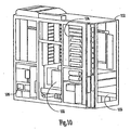
- chassis 112 is divided into four mechanical subsystems, of which each mechanical subsystem supports four node modules 10 and two router modules 70. Two mechanical subsystems are packaged into identical halves of the chassis assembly, as is shown in Fig. 10 .
- each mechanical subsystem operates independently from other subsystems.
- a mechanical subsystem includes a brick cooling unit (BCU) 120, AC power components and power supplies, module cage, connector rails and cables, and a system controller. Besides the frame, the only component that the mechanical subsystems share is blower unit 122.
- the cabinet is a custom built frame that is constructed out of 6061 T6 aluminum.
- the liquid-cooled cabinet with a full complement of modules 10 and 70, weighs approximately 1400 kg.
- the cabinet is approximately 2.4 m long, 0.9 m wide and 2.1 m tall. The cabinet consumes approximately 90 kW of AC power.
- a module card cage 124 is located on each side of chassis 112. Card cage 124 provides as mounting location for modules 10 and 70 in the chassis for aligning them to the system cable and power connectors.
- each card cage assembly contains eight node modules 10 that are located in the bottom eight rails locations.
- the top four rail locations are where the router modules are placed.
- the communication between the modules is provided with three separate cable types, a flex cable, a ribbon cable, and a shielded twisted wire pair cable.
- the flex cable is used for all interconnections lengths that do not exceed 36 cm, the ribbon cable for lengths less than 1.2 m, and the shielded cable for all lengths that exceed 1.2 m.
- Cabling between the sections in a cabinet are routed through the top of the cabinet. Cabling that occurs between cabinets is routed up through the top of the cabinets to cabling trough 110. This technique for cabling multiple cabinets together can also be used to cable to an IO cabinet.
- chassis 112 operates with a supply voltage between 180 and 263 volts AC, at either 50 or 60 Hz power.
- the chassis requires four 100 amp, 3 phase, 4 or 5 wire power cords (depends on site location) for operation.
- the AC power cords are fed into an AC power box that is located in the lower sections in the side of the chassis (refer to Fig. 10 ).
- power box 126 contains AC filters, breakers, terminal blocks, and controls.
- the power from AC power 126 box is fed directly to the AC power supplies that are located directly below the module card cages.
- the power supplies convert the AC power to 48 volt DC, which is then bused up the inside of the chassis to the module locations.
- the 48 volt DC power is connected to the module upon insertion into the chassis via a blind-mate power connector located on the back of the module.
- the 48 volt DC is then distributed to the DC power converters on the module via a copper laminated bus.
- Force convection air cooling is used for the low power ICs, such as the memory ICs, all SCM packages, and the miscellaneous discretes and SEC for the high power components that are mounted on MCM 26.
- force convection air flow required in the cabinet is supplier by a central centrifugal blower 122 as shown in Fig. 10 .
- the blower is capable of moving 4000 CFM throughout the air distribution system within chassis 112.
- the air used for forced convection cooling is recirculated within the system. The reason for this approach is to eliminate any computer room air distribution problems when more than one cabinet system is placed within the same computer room.
- the centrifugal blower pushes the warm air returning from the modules, at approximately 45°C, through water cooled tube-and-fin heat exchangers 130 (refer to Fig. 11 ) mounted on both sides of the cabinet.
- the air exits heat exchangers 130 chilled to a temperature of approximately 30°C.
- the air is then directed up the sides of the chassis to air plenums at the top of the cabinet.
- the air plenums direct the air to the front of the sides of the cabinet.
- the air is then directed down to the front of the modules where the module ducts (covers) funnel the air across the component heatsinks and into the return air plenum located directly above central blower 122.
- the module air vents are shown located on the card cage back plate. These vents are opened upon insertion of the module into the chassis.
- the vent door when a module is not seated into a slot the vent door is closed, the vent door simulates the pressure drop through the module so that the air distribution will not be affected if a module is not present.
- the brick cooling units depicted in Fig. 12 are used to provide and condition the fluid that is required for the spray evaporative cooling of the components on the MCM modules 22.
- the BCU is a semihermetic cooling system that is constructed with stainless steel and aluminum components.
- the fluid pump 180 is a magnetically coupled gear pump that is capable of supplying 20 liters/min of FC72 at 35 psid to node modules 10.
- the fluid passes through a particulate filter 182 as it exits the pump 180 and then through stainless tubing to the supply manifolds 186.
- the fluid then passes to node module 10 from the manifold 186 through quick disconnect couplings 184 that are used for mating the module hose to the chassis manifold.
- the mixed phase fluid exits the node module it passes through a pair of hoses and quick disconnect couplings 188 before it passes into the chassis return manifolds 190. From the return manifold 190 the mixed phase fluid enters into the heat exchanger 192, where the fluid is separated, condensed, and subcooled before it returns to the gear pump to complete the circulation loop.
- the system has a bypass circuit to insure the continued condition of the fluid.
- the bypass circuit has filters that continually remove organics, moisture, particulates, and any perfluoroisobutylenes (PFIB) that may be generated in the system due to the breakdown of the cooling fluid, Fluorinert (FC72).
- the cooling system has indicators imbedded in the cooling loop that indicate the condition of the fluid and when the filters need to.be replaced.
- the bypass filters can be replaced while the system is running.
- each computer system has a System Work Station (SWS).
- SWS is a computer that holds the boot code required to bring up the system and also provides a user interface for monitoring of the system's status and controlling its operation.
- the SWS communicates to the system hardware via an ethernet connection to a System Controller (L1).
- L1 controllers for each module 10 and 70 in the chassis and on each BCU.
- the L1 performs multiple functions which include the warning and control for system operation, JTAG, boundary scan, configuration management, maintenance, and remote support access.
- the L1 controller is a custom designed microprocessor with external SDRAM, FLASH, NVRAM and a 100Base-T ethernet port.
- the L1 also contains a micro controller (L0), which provides environmental monitoring and protection for the system.
- the L0 is a 16-bit micro controller that reads signals from various system sensors and controls the power and cooling systems. Environmental status of the system (voltages, temperatures, pressures, etc.) can be monitored from the SWS.
- the L1s are powered from the chassis's mains input power source, allowing the controller to be accessed without the mainframe operating.
- control system is designed to allow each module to operate independently of the other modules. If a module needs to be replaced or repaired it can be removed without bringing down other modules in the system.
- a method of cooling an enclosure in another embodiment, incorporates the above-described structure therein.
- a method of cooling an electronics enclosure is provided in another embodiment. The method includes forcing air over a first set of electronic components and cooling the first set of electronic components, heating a liquid to a temperature near its boiling point, directing the heated liquid against a second set of electronic components where at least portion of the heated liquid vaporizes, drawing the vapor and the heated liquid away from the electronics components, condensing the vapor back into liquid, and cooling the air and recirculating the air through the enclosure, where the air is maintained within the enclosure in a closed system.
- the method further includes recirculating the liquid, where the liquid and vapor are maintained within the enclosure in a closed system.
- the method further includes filtering the liquid, or charging the liquid with a non-corrosive gas.
- directing the heated liquid against the second set of electronic components includes directing the heated liquid against electronic components having a higher power than the first set of electronic components.
- a method of cooling an electronics enclosure having a plurality of electronics components includes directing a gas over electronic components and cooling the first set of electronic components, cooling the gas within the electronics enclosure, and recirculating the gas within the enclosure, where the air is maintained within the enclosure in a closed system.
- cooling the gas includes passing the gas through a water cooled heat exchanger.
- recirculating the gas includes directing the gas up sides of the enclosure to air plenums at the top of the enclosure.
- the method further optionally includes funneling the gas across heatsinks thermally coupled with the electronic component.
- computer is defined to include any digital or analog data processing unit. Examples include any personal computer, workstation, set top box, mainframe, server, supercomputer. laptop or personal digital assistant capable of embodying the inventions described herein.
Landscapes
- Engineering & Computer Science (AREA)
- Microelectronics & Electronic Packaging (AREA)
- Physics & Mathematics (AREA)
- Condensed Matter Physics & Semiconductors (AREA)
- General Physics & Mathematics (AREA)
- Computer Hardware Design (AREA)
- Power Engineering (AREA)
- Thermal Sciences (AREA)
- Cooling Or The Like Of Electrical Apparatus (AREA)
Abstract
Description
- The present invention is related to cooling of electronic equipment, and more particularly to cooling electronics components.
- Demand for higher performance supercomputers continues to create challenging thermal and packaging design environments for today's computer packaging engineers. As the performance of CRAY supercomputers continues to grow exponentially, in general agreement with Moore's law (Bar-Cohen, et al, 1988), the thermal and packaging solutions continue to become more complex.
- The increase of supercomputer performance over the last 30 years was initially achieved with an increase in the complexity of the computer's CPU by increasing the number of ICs within a CPU. The next step in performance was achieved by adding more gates per IC along with increasing the clock rate. Performance was further increased by the paralleling of CPUs and then the scaling of groups of CPUs. Now in order to continue on the path of Moore's law, we are again pushing the IC technology and ultimately the performance of each individual CPU.
- One technology that hasn't been able to keep pace with the ICs is the printed circuit board (PCB) technology. The demands for component placement and IC net routings have exceeded the current state of the art in PCB technology.
- One solution to this problem implements a multi-chip module with thin film routing layers (MCM-D) for the packaging of these high performance chip sets. This high density packaging design is, however, capable of producing heat fluxes on the ICs and MCM that approach values of 50 and 15 W/cm2, respectively. The control of the IC's junction temperature is important for its reliability and for the performance of two communicating devices. The amount of induced leakage "noise" that exists on an integrated circuit is also a junction of its temperature.
- A number of cooling methodologies have been described by Bar-Cohen (Bar-Cohen, A., "Thermal Management of Electronic Components with Dielectric Liquids", JSME International Journal, Series B, vol. 36, No1,1993), by Simons (Simons, R.E., "Bibliography of Heat Transfer in Electronic Equipment", 1989, IBM Corporation), by Incropera (Incropera, F. P., "Convection Heat Transfer in Electronic Equipment Cooling", Journal of Heat Transfer, Nov. 1988, Vol. 110/1097) and by Bergles (Bergles. A. E., "liquid Cooling for Electronic Equipment", International Symposium on Cooling Technology for Electronic Equipment, March 1987). Studies by Chu and Chrysler (Chu, R.C:, and Chrysler, G. M., "Electronic Module Coolability Analysis", EEP-Vol. 19-2. Advances in Electronic Packaging-1997 Volume 2, ASME 1997) and by Nakayama (Nakayama, W., "Liquid-Cooling of Electronic Equipment: Where Does It Offer Viable Solutions?", EEP-Vol. 19-2, Advances in Electronic Packaging-1997 Volume 2, ASME 1997), however, indicate that these approaches are no longer capable of satisfying todays high density packaging requirements (Chu and Chrysler, 1997), (Nakayama, 1997).
- As heat flux continues to increase, the most promising methods are those that utilize direct liquid cooling with dielectric fluids. Direct liquid cooling circumvents the problems of high thermal interface resistance associated with conventional technologies and is capable of providing very high heat transfer rates (Bar-Cohen, 1993). A number of such direct liquid cooling techniques are described in, "Thermal Management of Multichip Modules with Evaporative Spray Cooling," by G. W. Pautsch and A. Bar-Cohen, published in ASME Advances in Electronic Packaging 1999, EEP-Vol.26-2, 1453-1463, the discussion of which is incorporated herein by reference. That paper concluded that the method of choice for cooling high heat flux electronic components is describe as "High Density, Pressure-Atomized Evaporative Spray Cooling". This condition occurs when a fluid is sprayed on a surface at a rate that maintains a continuously wetted surface, whose temperature is less than 25°C above the saturation temperature of the thermal coolant. This method, with the selection of an appropriate fluid, such as Fluorinert™ FC-72 which has a boiling point of 56°C at standard atmospheric conditions, allows one to maintain high heat flux components at operating temperatures below 85°C.
- Each of the above cooling approaches has its deficiencies. What is needed is a system and method for cooling electronics components that addresses these deficiencies.
-
WO 01/20962 - To address the problems stated above, and to solve other problems which will become apparent in reading the specification and claims, a system and method for cooling electronic components is described herein.
- In a first aspect, the present invention provides a coiling assembly as recited in claim 1.
- Several options for the assembly are as follows. For instance, in one option, the at least one spray evaporative cooling assembly and the at least one fluid conditioning unit form a closed system. In another option, the chassis forms a closed system therein. In yet another option, the at least one fluid conditioning unit includes at least one pump and a heat exchanger. The spray evaporative cooling assembly, in another option, includes a fluid charged with a non-corrosive, inert gas, for example Nitrogen.
- In a second aspect, the present invention provides a method as recited in claim 7.
- Several options for the method are as follows. For example, in one option, the method further includes recirculating the liquid, where the liquid and vapor are maintained within the enclosure in a closed system. In another option, the method further includes filtering the liquid, or charging the liquid with a non- corrosive gas. In another option, directing the heated liquid against the first set of electronic components includes directing the heated liquid against electronic components having a higher power than the second set of electronic components.
- In yet another embodiment, a method of cooling an electronics enclosure having a plurality of electronics components includes directing a gas over electronic components and cooling the first set of electronic components, cooling the gas within the electronics enclosure, and recirculating the gas within the enclosure, where the air is maintained within the enclosure in a closed system.
- Several options for the method are as follows. For instance, in one embodiment, cooling the gas includes passing the gas through a water cooled heat exchanger. Optionally, recirculating the gas includes directing the gas up sides of the enclosure to airplenums at the top of the enclosure. The method further optionally includes funneling the gas across heatsinks thermally coupled with the electronic components.
- These and other embodiments, aspects, advantages, and features of the present invention will be set forth in part in the description which follows, and in part will become apparent to those skilled in the art by reference to the following description referenced drawings or by practice of the invention. The aspects, advantages, and features of the invention are realized and attained by the system, apparatus, procedures, and combinations particularly pointed out in the appended claims and their equivalents.
- In the following drawings, where the same number reflects similar function in each of the drawings,
- Figure 1
- illustrates a node module constructed in accordance with one embodiment;
- Figure 2
- illustrates a node module constructed in accordance with one embodiment;
- Figure 3
- illustrates a node module constructed in accordance with one embodiment;
- Figure 4
- illustrates a node module constructed in accordance with one embodiment;
- Figure 5
- illustrates a node module constructed in accordance with one embodiment;
- Figure 6
- illustrates a node module constructed in accordance with one embodiment;
- Figure 7
- illustrates a router module constructed in accordance with one embodiment;
- Figure 8
- illustrates a router module constructed in accordance with one embodiment;
- Figure 9
- illustrates a four chassis computer system constructed in accordance with one embodiment;
- Figure 10
- illustrates a single chassis optionally used in the system of
Figure 9 constructed in accordance with one embodiment; - Figure 11
- illustrates air cooling and I/O connections in a system such as is shown in
Figure 10 constructed in accordance with one embodiment; - Figure 12
- illustrates a cooling unit which can be used to cool a liquid coolant constructed in accordance with one embodiment; and
- Figure 13
- illustrates a spray cap constructed in accordance with one embodiment.
- In the following detailed description of the preferred embodiments, reference is made to the accompanying drawings which form a part hereof, and in which is shown by way of illustration specific embodiments in which the invention may be practiced. It is to be understood that other embodiment may be utilized and structural changes may be made without departing from the scope of the present invention.
- The present embodiments will be described in the context of the SV2 computer manufactured by Cray Inc. of Seattle, Washington. The CRAY® SV2 computer is a highly scalable, cache coherent, shared memory multiprocessor supercomputer using powerful vector processors as its building blocks. The core building block of the system is an eight chip multi-streaming processor (MSP) which is packaged on a multichip module (MCM) and placed on a printed circuit board. Each MCM generates a great deal of heat, and the heat must be transferred away from the MCM.
- There are two module types used in the CRAY SV2 system: a node module and a router module. The node module contains the systems' MSPs, its associated memory and communication channels. The router modules are symmetric 8- port crossbars that provide multiple independent interconnection networks for the system.
- A
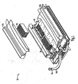
node module 10 suitable for use in a highly dense computer such as the SV2 supercomputer is shown inFig. 1 . In themodule 10 ofFig. 1 , both air and liquid cooling are used to cool the electronic components withinmodule 10. Eachmodule 10 includes aliquid cooling manifold 12 for carrying an inert coolant such as FC-72. In the embodiment shown,manifold 12 extends across a group of higher power electronic components running down the center ofmodule 10. Other configurations could be used as well. - In the embodiment shown,
manifold 12 includes aninput hose 14 and two output hoses 16.1 and 16.2. In addition, two air cooling manifolds (18.1 and 18.2) direct air across lower power electronic components (such as daughter cards 20) withinmodule 10. Gases other than air.could also be used to cool the lower power electronic components withinmodule 10. - An exploded view of
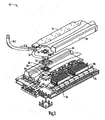
module 10 is shown inFig. 2 . Inmodule 10 ofFig. 2 ,liquid cooling manifold 12 has been disconnected frommodule 10 to exposeMCM modules 22. In the embodiment shown, eachmodule 10 includes fourMCM modules 22. EachMCM module 22 includes a sprayevaporative cap 24, anMCM 26 and acompliant interconnect 28 held within acompliant interconnect frame 30. In the embodiment shown,manifold 12 includesinput adapters 32 and output adapters 34 for injecting and removing liquid, respectively, fromMCM module 22. - An even more exploded view of one embodiment of
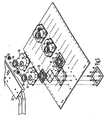
module 10 is shown inFig. 3 . In the embodiment shown inFig. 3 , eachmodule 10 includes a cold plate 44. Other configurations could be used as well. - In
module 10 ofFig. 3 ,manifolds 12, 18.1, and 18.2 (Figs. 1 and2 ) have been removed frommodule 10 to exposeMCM modules 22 anddaughter card connectors 36. In the embodiment shown, eachmodule 10 includes fourMCM modules 22. EachMCM module 22 includes a sprayevaporative cap 24, anMCM 26, acompliant interconnect 28 and acompliant interconnect frame 30. In the embodiment shown, a backer plate 38 with eightposts 40 is inserted through an insulator 42, a cold plate 44, aninsulator 46 and a printedcircuit board 48 such that theposts 40 extend beyond printedcircuit board 48.Compliant interconnect frame 30 is aligned with and placed overposts 40 such that posts 40 extend throughframe 30 and intoopenings 50 withincap 24. - In one embodiment, tempered steel springs 52 are placed over
posts 40 and held in compression using a snap ring locked within a groove on eachpost 40. In one such embodiment,MCM 26 andcap 24 are assembled together before being placed overposts 40. Springs 52 are then placed overposts 40 and compressed such that a compression of 350 to 400 pounds of pressure is placed oncaps 24, securely holdingMCM 26 in place. Such an approach ensures the electrical connection betweenMCM 26 and printedcircuit board 48 without the need for flow soldering or other permanent connection. - The CRAY SV2 supercomputer is Cray's first product to use MCM technology. The product design required an 83 layer MCM substrate that was fabricated using glass ceramic and copper conductor construction. Its physical size is 72 mm square and 8.3 mm thick. The MCM substrate is made up of 18 plane pairs of X-Y routing; the balance of the layers are power and ground. The copper signal lines are either 85 or 100 µ wide, 20 µ thick, and are routed on a 450 µ. pitch. The impedance of the traces are 55 Ωs.
- In one embodiment, there are eight ASICs mounted on each
MCM 26 substrate, along with 80 decoupling capacitors In one such embodiment, these devices are assembled onto the MCM substrate using Controlled Collapse Chip Connections (C4s) such as described in Microelectronics Packaging Handbook (Tummala, R. R, Rymaszewski, E. J., Van Nostrand Reinhold Publishing, 1989). - In one embodiment, approximately 34000 C4 pads are placed on the top surface metal layer (TSM) of which approximately 8000 are signal; the remaining are power and ground These ASICs are approximately 16 or 17 mm square. On the bottom of
MCM 26 there are 3832 Land Grid Array (LGA) pads. Approximately half the pads are signal; the remaining are power and ground. These pads are electrically attached toPCB 48 with a compliant interconnect system. - The CRAY SV2 supercomputer employs a custom designed compliant Land Grid Array (LGA) connector system that electrically connects a
demateable MCM 26 to theNode module 10'sPCB 48. Each LGA connector system is made up of 3832 contacts on a 1mm pitch. The contacts are divided into four identical quadrants. - In one embodiment,
MCM 26 alignment is obtained by the socket insulator spring/fence centering MCM 26 within the socket. In one such embodiment, a unique pattern was established between the signal 1/0 and the power and ground contacts for reducing crosstalk in the LGA connector system. The quadrant carriers each have an array size of 31 rows square, presenting up to 961 high compliant, non-yielding (.012 inch travel, low force (40 grams per contact), low contact and bulk resistance (<0.015 milli-ohm at 0.75 amps), low inductance (<1.5 nH at 500-1000 MHz) contacts that connect gold plated pads on the top surface ofPCB 48 to gold plated pads on the bottom surface metal (BSM) ofMCM 26. The force required for electrical contact between the MCM and the PCB is provided with spring compression hardware that has been integrated into the thermal management's spray evaporative cooling cap as described above. In one embodiment, the cap assembly maintains a normal force of 65 grams per contact. Assembly of the system is facilitated by a custom gang compression and spring removal tool which acts as a collet around the MCM cooling cap assembly. - In one embodiment,
PCB 48 is used to connect the MSP processing unit within each of theMCM modules 22 to the memory daughter cards, to other modules, and to the IO channels for front-end communication. To make all of these connections requires 17,000 differential and single ended nets in the PCB. In one embodiment, in order to connect these nets to the components there are 70,000, 0.28 mm diameter plated through holes. - In one embodiment, there are 34 metal layers in
PCB 48. Sixteen layers are power/ground layers, 16 paired signal layers, one layer is a TSM and one layer is a BSM. In one such embodiment, each layer pair has approximately 4,000 buried vias which connect the plane pair together to aid in the routing of the signals. The total number of drilled holes in the PCB is approximately 100,000. - In one embodiment, the via grid in
PCB 48 is 1 mm, which allows two routes perchannel Board 48, in one option, is 558 mm by 431 mm and is approximately 3.56 mm thick. In another option, the PCB is constructed from an organic material with a Er of approximately 3.4. - In one embodiment, the characteristic impedance of the differential lines are 100 Ωs ; the single ended lines are 45 Ωs. The signal lines are 0.076 mm wide and are on 0.18 mm and 0.28 mm pitches.
- The CRAY SV2 supercomputer employs synchronous switching DC-DC power converters that operate at approximately 80% efficiency. This converter was designed to meet Cray's specific electrical design requirements and physical form factors. Each DC-DC power converter convert 48 volts DC input power to 1.8 or 2.5 volts DC output power with an output current of 190 amps or 125 amps, respectively.
- Because of the high efficiency of these converters, they are conduction cooled with the same fluid that is use to spray evaporative cool each
MCM module 22. Such an embodiment is shown inFig. 4 . In themodule 10 ofFig. 4 , a plurality of DC-DC converters 50 are mounted on a side of PCB 48 (Fig, 3 ) opposite MCM modules 22 (Fig. 3 ). Eachconverter 50 is placed in thermal contact with cold plate 44. Coolant fluid received atmodule 10 is distributed through channels within cold plate 44 in order to conductivelycool converters 50 before that coolant is used to coolMCM modules 22. - One advantage of cooling the
converters 50 before coolingMCM modules 22 is that heat fromconverters 50 is used to raise the temperature of the cooling fluid to a temperature near the fluid's boiling point. This increases the amount of fluid that vaporizes when it comes into contact withMCMs 26. - In one embodiment,
converter 50's mean time between failure (MTBF) is greater than 1,000,000 hours and is designed to operate in a parallel, N+1 configuration, which makes a very reliable power supply assembly for the SV2 modules. The power density of the converter is greater than 16 W/in3 and employs electronic inrush control, current shares, voltage margins, and has enable feature controls. - Spray Evaporative Cooling (SEC) was selected as one of the enabling technologies for this supercomputer because of its ability to effidently and effectively cool high power density ASICs and its ability to minimize temperature variation between ASICs at different power levels. Spray Evaporative Cooling is a process where a fluid is sprayed onto the surface of a high power ASIC at a rate that maintains a continuously wetted surface. The fluid on the hot surface then absorbs the heat and evaporates, thus removing the heat from the surface of the high power ASIC. Spray Evaporative Cooling is used to maintain the junction temperatures of the ASICs on each
MCM 26 between 70° and 85°C. The heat flux on these ASICs range from 15 W/cm2 to 55 W/cm2. In one embodiment, the cooling fluid used in this application is 3M's dielectric fluorocarbon. FC72. Its boiling temperature is 56°C at 1 atmosphere pressure. The established flow rate requirement for the MCM design shown is approximately 1 ml/mW/min. - In one embodiment, system design and reliability considerations led to the choice of pressure-atomization (Pais, et al, 1989), rather than secondary-gas-assisted choice of pressure atomization for this application. In one such embodiment, the nozzle design used is a full cone pressure swirl chamber such as shown in
Fig. 3 of "Atomization and Sprays" by A. H. Lefebvre, Taylor & Francis Publishing, 1989. - In one embodiment,
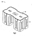
node module 10 is a single PCB assembly that is mounted onto an aluminum coldplate such as coldplate 44.Node module 10, in one option, includes four MSPs, each containing four processors and four cache chips mounted on anMCM 26. One example of such anMCM 26 is shown inFig. 5 . In the example shown inFig. 5 , "O" rings 52 and 54seal module 12 toadapters 32 and 34, respectively. In addition, an "O" ring 56 can be used to sealadapter 32 and 34 to cap 24 as is show inFig. 5 . - In one embodiment, the four
MCM modules 22 are mounted in a row down the center of the PCB assembly as shown inFig. 2 .MCM modules 22 are mounted to the PCB using the cap assembly in the manner described earlier. A backing plate 38 is used to support the PCB against the load of the compliant interconnect systems that is providing the contact betweenMCMs 26 andPCB 48. - In one embodiment, local memory for the node module includes 32
daughter cards 20. In one such embodiment, such as is shown inFig. 3 ,memory daughter cards 20 are mounted ontoPCB 48 in four groups of eight cards. In the embodiment shown, two groups of the eight cards are mounted on each side of the MCMs. - As noted above,
daughter cards 20 are cooled by forced convection with air. To meet the system's environmental requirements, in one embodiment a heat spreader was designed and placed on the TSOPs to enhance the heat transfer process. The thermal resistance of the heat spreader design is 16°C/W for air velocities of 1200 fpm. Molded covers are then placed over each of the two array of cards to channel the air that is being drawn in from the front of the module, through to the back where the air is then exhausted into the chassis return air plenum. - In one embodiment, such as is shown in
Fig. 2 , eight organic ball grid array (BGA) single chip modules (SCM) 21 are placed between thedaughter cards 20 and twooutside edges ofPCB 48.Modules 21 support the functions of memory controller, network interfacing, cache coherence directories, and management of off module communication channels. - These off module communication channels are connected to other node or router modules via differential signal pair wires that are housed in thirly-two blind mate, cam actuated, controlled impedance edge connectors (refer to
Fig. 4 &5 ). These 16 BGAs are air-cooled with reverse impingement heat sinks. These heat sink have a thermal resistances of 1.25°C/W. - In one embodiment, the molded cover that is used for directing air across the
memory daughter cards 20 also channels 4 cfm of air individually through each of these heat sinks. The power level of the ICs and the associated caloric temperature rise of the air through the hat sink dictated this cooling approach. The air is channeled into the heat sinks over the edge connectors and is then drawn out through the rear of the module into the chassis return air plenum. - In one embodiment, each
node module 10 has two I/O channel SCMs 51. Each I/O channel SCM 51 provides two IO channels. In one such embodiment, these SCMs are located onPCB 48 directly in front ofmemory daughter cards 20, as shown inFig. 6 . These two SCMs each have a heat sink mounted to them to dissipate their heat. In one embodiment, the air that is drawn across the memory daughter cards is first used for the cooling of these two SCMs. - In one embodiment, the DC power required by the ICs on
module 10 is provided by 14 DC-DCsynchronous power converters 50. The power converters are mounted on the top side of coldplate 44. Incoming power to the converters is provided, in one option, at 48 volts DC. This power is supplied to the converters via blind mate connectors that connect to the power distribution busses that are located in the chassis. In one embodiment, the input voltage is distributed to each of the converters via two laminated flexible bus bars. The output power bus fromconverters 50 is designed to enable the 1.8 volt converters (quantity of 11) and the 2.5 volt converters (quantity of 4) to operate independently in an N+1 configuration. The output power busses connect tomodule 10 via bus blocks that are soldered to voltage pads located on the bottom ofPCB 48, and extend through an opening in coldplate 44. - As noted above, in one
embodiment converters 50 are high efficiency converters which dissipate their heat losses via conduction to coldplate 44. Coldplate 44 is designed with internal passages to allow coolant to pass through and remove the dissipated heat from the power converters. Other mechanisms for placing the coolant in thermal contact withconverters 50, such as a manifold, could also be used. - Referring again to
Fig. 2 , in one embodiment, the coolant is supplied tomodule 10 through a singlestainless steel hose 14 that connects to a fluid distribution manifold on the chassis. The coolant flows through the hose assembly into an aluminum coldplate 44 that the PCB assembly is mounted onto. Coldplate 44 allows the coolant to flow through it from the front ofmodule 10 to the rear. At the rear ofmodule 10, in one option, the fluid entersmodule distribution manifold 12 and is distributed to each of the fourMCM modules 22. - In one embodiment, as is shown in
Fig. 6 , "O" ring 58 seals the connections betweenhose 14 and coldplate 44. In a similar manner, "O" ring 59 seals the connection between coldplate 44 andmanifold 12. - When the coolant is sprayed onto the integrated circuits on MCM 26 (
Fig. 1 ) and gone through a phase change it then existsmodule 10 through a pair of stainless steel hoses 16.1 and 16.2 to a return manifold on the chassis. - In one embodiment, such as is shown in
Fig. 4 ,module controller 60 monitors the operating conditions of the components onmodule 10 and controls its operation based on this information. - The second module type in the SV2 supercomputer is a router module. The function of this module is to provide multiple independent interconnection networks for the MSPs on
node module 10. - In one embodiment, as is shown in
Fig. 7 ,router module 70 includes twoPCB assemblies 72 mounted on opposite sides of analuminum coldplate 74. EachPCB assembly 72 includes, in one option, fourrouter chips 78 mounted on the outside edge of the PCB next to the edge connectors. In one such embodiment, the router chips are air cooled in a similar fashion as the I chip on the node module, - In one embodiment, manifolds 80 (
Fig. 8 ) are placed onmodule 70 to direct the air across the heat sinks and into the return air plenum in the chassis. In the center of the top side of the module are located two DC-DC power converters. These converters provide the power for the router chips on both of the PCB assemblies that are mounted to thesame coldplate 74. These converters are mounted on air cooled heatsinks and cooled by force convection. A duct is again mounted over the heat sinks to direct the air. The 48 volt input power to the router module is provided in the same fashion as it was tonode module 10. - In one embodiment,
edge connectors 76 onrouter module 70 are identical to theedge connector 11 used on node module 10 (Fig. 1 ). In one such embodiment, the number of edge connectors perrouter PCB 72 is exactly the same as onnode PCB 48. The router module, with its two PCB, has twice the quantity of edge connectors as node module 10 (Fig. 4 ). - In one embodiment,
router module 70 also has a module controller 90 mounted on the top side of the module assembly. It performs a similar function for the router module as doescontroller 60 for node module 10 (Fig. 4 ). - One embodiment of a four chassis, liquid-cooled
supercomputer system 100 is shown inFig. 9 . In the configuration shown inFig. 9 ,overhead cabling troughs 110 connect each of the fourchassis 112. -
Supercomputer system 100 can also be implemented as an air-cooled model. Both the air and liquid-cooled models use similar components as their building blocks. The basic difference between the two chassis types is that all of the heat generated by the air-cooled chassis is rejected to room air, where the liquid-cooled chassis rejects all of the heat it generates to facility water. The two chassis are both stand alone cabinets that don't require any additional mechanical, electrical, or environmental support equipment for its operation. It should be noted that the chassis configuration inFig. 9 does not show any of the required system components, such as a input/output (IO) cabinet, disc drives, and etc., for communicating to and supporting the system. - In one embodiment, each
chassis 112 is designed to support sixteen node modules and eight router modules. In one such embodiment,chassis 112 is divided into four mechanical subsystems, of which each mechanical subsystem supports fournode modules 10 and tworouter modules 70. Two mechanical subsystems are packaged into identical halves of the chassis assembly, as is shown inFig. 10 . - In one embodiment, each mechanical subsystem operates independently from other subsystems. A mechanical subsystem includes a brick cooling unit (BCU) 120, AC power components and power supplies, module cage, connector rails and cables, and a system controller. Besides the frame, the only component that the mechanical subsystems share is
blower unit 122. - In one embodiment, the cabinet is a custom built frame that is constructed out of 6061 T6 aluminum. The liquid-cooled cabinet, with a full complement of
modules - In one embodiment, a
module card cage 124 is located on each side ofchassis 112.Card cage 124 provides as mounting location formodules - In one embodiment, each card cage assembly contains eight
node modules 10 that are located in the bottom eight rails locations. The top four rail locations are where the router modules are placed. The communication between the modules is provided with three separate cable types, a flex cable, a ribbon cable, and a shielded twisted wire pair cable. The flex cable is used for all interconnections lengths that do not exceed 36 cm, the ribbon cable for lengths less than 1.2 m, and the shielded cable for all lengths that exceed 1.2 m. - Cabling between the sections in a cabinet are routed through the top of the cabinet. Cabling that occurs between cabinets is routed up through the top of the cabinets to
cabling trough 110. This technique for cabling multiple cabinets together can also be used to cable to an IO cabinet. - In one embodiment,
chassis 112 operates with a supply voltage between 180 and 263 volts AC, at either 50 or 60 Hz power. The chassis requires four 100 amp, 3 phase, 4 or 5 wire power cords (depends on site location) for operation. The AC power cords are fed into an AC power box that is located in the lower sections in the side of the chassis (refer toFig. 10 ). - In one such embodiment,
power box 126 contains AC filters, breakers, terminal blocks, and controls. The power fromAC power 126 box is fed directly to the AC power supplies that are located directly below the module card cages. The power supplies convert the AC power to 48 volt DC, which is then bused up the inside of the chassis to the module locations. The 48 volt DC power is connected to the module upon insertion into the chassis via a blind-mate power connector located on the back of the module. The 48 volt DC is then distributed to the DC power converters on the module via a copper laminated bus. - As noted above, two distinct methods of cooling are used in the SV2 supercomputer for thermal management. Force convection air cooling is used for the low power ICs, such as the memory ICs, all SCM packages, and the miscellaneous discretes and SEC for the high power components that are mounted on
MCM 26. - In one embodiment, force convection air flow required in the cabinet is supplier by a central
centrifugal blower 122 as shown inFig. 10 . The blower is capable of moving 4000 CFM throughout the air distribution system withinchassis 112. The air used for forced convection cooling is recirculated within the system. The reason for this approach is to eliminate any computer room air distribution problems when more than one cabinet system is placed within the same computer room. - The centrifugal blower pushes the warm air returning from the modules, at approximately 45°C, through water cooled tube-and-fin heat exchangers 130 (refer to
Fig. 11 ) mounted on both sides of the cabinet. The air exitsheat exchangers 130 chilled to a temperature of approximately 30°C. The air is then directed up the sides of the chassis to air plenums at the top of the cabinet. The air plenums direct the air to the front of the sides of the cabinet. The air is then directed down to the front of the modules where the module ducts (covers) funnel the air across the component heatsinks and into the return air plenum located directly abovecentral blower 122. - an
Fig. 10 the module air vents are shown located on the card cage back plate. These vents are opened upon insertion of the module into the chassis. In one embodiment, when a module is not seated into a slot the vent door is closed, the vent door simulates the pressure drop through the module so that the air distribution will not be affected if a module is not present. - The brick cooling units depicted in
Fig. 12 , are used to provide and condition the fluid that is required for the spray evaporative cooling of the components on theMCM modules 22. In one embodiment, the BCU is a semihermetic cooling system that is constructed with stainless steel and aluminum components. The fluid pump 180 is a magnetically coupled gear pump that is capable of supplying 20 liters/min of FC72 at 35 psid tonode modules 10. The fluid passes through a particulate filter 182 as it exits the pump 180 and then through stainless tubing to the supply manifolds 186. The fluid then passes tonode module 10 from the manifold 186 through quick disconnect couplings 184 that are used for mating the module hose to the chassis manifold. - In one embodiment, as the mixed phase fluid exits the node module it passes through a pair of hoses and quick disconnect couplings 188 before it passes into the chassis return manifolds 190. From the return manifold 190 the mixed phase fluid enters into the heat exchanger 192, where the fluid is separated, condensed, and subcooled before it returns to the gear pump to complete the circulation loop.
- In conjunction with the main circulation loop, the system has a bypass circuit to insure the continued condition of the fluid. The bypass circuit has filters that continually remove organics, moisture, particulates, and any perfluoroisobutylenes (PFIB) that may be generated in the system due to the breakdown of the cooling fluid, Fluorinert (FC72). The cooling system has indicators imbedded in the cooling loop that indicate the condition of the fluid and when the filters need to.be replaced. The bypass filters can be replaced while the system is running.
- In one embodiment, each computer system has a System Work Station (SWS). The SWS is a computer that holds the boot code required to bring up the system and also provides a user interface for monitoring of the system's status and controlling its operation. The SWS communicates to the system hardware via an ethernet connection to a System Controller (L1). There are L1 controllers for each
module - In one embodiment, the L1 controller is a custom designed microprocessor with external SDRAM, FLASH, NVRAM and a 100Base-T ethernet port. The L1 also contains a micro controller (L0), which provides environmental monitoring and protection for the system. The L0 is a 16-bit micro controller that reads signals from various system sensors and controls the power and cooling systems. Environmental status of the system (voltages, temperatures, pressures, etc.) can be monitored from the SWS. The L1s are powered from the chassis's mains input power source, allowing the controller to be accessed without the mainframe operating.
- In one embodiment, the control system is designed to allow each module to operate independently of the other modules. If a module needs to be replaced or repaired it can be removed without bringing down other modules in the system.
- In another embodiment, a method of cooling an enclosure is described. The method, in one option, incorporates the above-described structure therein. A method of cooling an electronics enclosure is provided in another embodiment. The method includes forcing air over a first set of electronic components and cooling the first set of electronic components, heating a liquid to a temperature near its boiling point, directing the heated liquid against a second set of electronic components where at least portion of the heated liquid vaporizes, drawing the vapor and the heated liquid away from the electronics components, condensing the vapor back into liquid, and cooling the air and recirculating the air through the enclosure, where the air is maintained within the enclosure in a closed system.
- Several options for the method are as follows. For example, in one option, the method further includes recirculating the liquid, where the liquid and vapor are maintained within the enclosure in a closed system. In another option, the method further includes filtering the liquid, or charging the liquid with a non-corrosive gas. In another option, directing the heated liquid against the second set of electronic components includes directing the heated liquid against electronic components having a higher power than the first set of electronic components.
- In yet another embodiment, a method of cooling an electronics enclosure having a plurality of electronics components includes directing a gas over electronic components and cooling the first set of electronic components, cooling the gas within the electronics enclosure, and recirculating the gas within the enclosure, where the air is maintained within the enclosure in a closed system.
- Several options for the method are as follows. For instance, in one embodiment, cooling the gas includes passing the gas through a water cooled heat exchanger. Optionally, recirculating the gas includes directing the gas up sides of the enclosure to air plenums at the top of the enclosure. The method further optionally includes funneling the gas across heatsinks thermally coupled with the electronic component.
- In the above discussion and in the attached appendices, the term "computer" is defined to include any digital or analog data processing unit. Examples include any personal computer, workstation, set top box, mainframe, server, supercomputer. laptop or personal digital assistant capable of embodying the inventions described herein.
- Although specific embodiments have been illustrated and described herein, it will be appreciated by those of ordinary skill in the art that any arrangement which is calculated to achieve the same purpose may be substituted for the specific embodiment shown. This application is intended to cover any adaptations or variations of the present invention. Therefore, it is intended that this invention be limited only by the claims.
Claims (13)
- A cooling assembly comprising:a first set of electronic components (26) coupled with a substrate;a spray evaporative cooling cap assembly (24) coupled with the first set of electronic components;a cold plate (44) coupled with the substrate;a second set of electronic components (50) thermally coupled with the cold plate (44);cooling fluid within the spray evaporative cooling cap assembly and the cold plate (44), wherein the cold plate (44) includes internal passages therein and is configured such that the fluid flows from the internal passages to the spray evaporative cooling cap assembly (24), the spray evaporative cooling cap assembly (24) configured to direct the cooling fluid against a surface of the first set of electronic components (26); anda fluid conditioning unit associated with the spray evaporative cooling cap assembly (24).
- The cooling assembly as recited in claim 1, wherein the spray evaporative cooling cap assembly (24) and the fluid conditioning unit are a closed system.
- The cooling assembly as recited in claims 1 or 2, wherein the fluid is charged with an inert, non-corrosive gas.
- The cooling assembly as recited in any of claims 1 to 3, wherein the gas is Nitrogen.
- The cooling assembly as recited in any of claims 1 to 4, wherein the cold plate (44) pre-heats the fluid for the spray evaporative cooling cap assembly (24) with heat from the second set of electronic components (50).
- The cooling assembly as recited in any of claims 1 to 5, wherein the spray evaporative cooling cap assembly (24) includes a compliant interconnect assembly, the compliant interconnect assembly compressing at least one of the plurality of electronic components (26) against the substrate.
- A method of cooling an electronics enclosure having a plurality of electronics components the plurality of electronic components comprising a first set of electronic components (26) and a second set of electronic components (50), the method comprising:flowing a liquid through channels of a cold plate (44) coupled with a substrate and convectively cooling a second set of electronic components (50) thermally coupled with the cold plate (44);directing the liquid from the cold plate (44) against a first set of electronics components (26) such that a portion of the heated liquid vaporizes upon contact with a surface of the first set of electronic components (26);drawing the vapor and the heated liquid away from the first set of electronic components (26); andcondensing the vapor back into liquid.
- The method as recited in claim 7, wherein flowing the liquid through channels includes heating the liquid to a temperature near its boiling point.
- The method as recited in claim 7 or 8, further comprising charging the liquid with a non-corrosive, inert gas.
- The method according to claim 9, wherein charging the liquid includes charging the liquid with Nitrogen.
- The method according to claim 7, further comprising maintaining pressure of the liquid just above atmospheric pressure.
- The method according to any of claims 7 to 11, further comprising separating the vapor from the liquid prior to condensing the vapor into liquid.
- The method according to any of claims 7 to 12 wherein directing the liquid from the cold plate (44) against the first set of electronics components (26) includes directing the liquid into a spray evaporative cooling cap assembly thermally coupled to the first set of electronic components (26).
Priority Applications (1)
| Application Number | Priority Date | Filing Date | Title |
|---|---|---|---|
| EP10075670A EP2267771A3 (en) | 2001-05-16 | 2002-05-16 | Method and apparatus for cooling electronic components |
Applications Claiming Priority (3)
| Application Number | Priority Date | Filing Date | Title |
|---|---|---|---|
| US09/860,038 US6646879B2 (en) | 2001-05-16 | 2001-05-16 | Spray evaporative cooling system and method |
| US10/118,279 US6580609B2 (en) | 2001-05-16 | 2002-04-08 | Method and apparatus for cooling electronic components |
| EP02729218A EP1388277B1 (en) | 2001-05-16 | 2002-05-16 | Method and apparatus for cooling electronic components |
Related Parent Applications (2)
| Application Number | Title | Priority Date | Filing Date |
|---|---|---|---|
| EP02729218.4 Division | 2002-05-16 | ||
| EP02729218A Division EP1388277B1 (en) | 2001-05-16 | 2002-05-16 | Method and apparatus for cooling electronic components |
Related Child Applications (2)
| Application Number | Title | Priority Date | Filing Date |
|---|---|---|---|
| EP10075670A Division-Into EP2267771A3 (en) | 2001-05-16 | 2002-05-16 | Method and apparatus for cooling electronic components |
| EP10075670.9 Division-Into | 2010-10-01 |
Publications (3)
| Publication Number | Publication Date |
|---|---|
| EP2242345A2 EP2242345A2 (en) | 2010-10-20 |
| EP2242345A3 EP2242345A3 (en) | 2011-11-02 |
| EP2242345B1 true EP2242345B1 (en) | 2014-09-10 |
Family
ID=25332363
Family Applications (2)
| Application Number | Title | Priority Date | Filing Date |
|---|---|---|---|
| EP10006953.3A Expired - Lifetime EP2242345B1 (en) | 2001-05-16 | 2002-05-16 | Method and apparatus for cooling electronic components |
| EP10075670A Withdrawn EP2267771A3 (en) | 2001-05-16 | 2002-05-16 | Method and apparatus for cooling electronic components |
Family Applications After (1)
| Application Number | Title | Priority Date | Filing Date |
|---|---|---|---|
| EP10075670A Withdrawn EP2267771A3 (en) | 2001-05-16 | 2002-05-16 | Method and apparatus for cooling electronic components |
Country Status (4)
| Country | Link |
|---|---|
| US (2) | US6646879B2 (en) |
| EP (2) | EP2242345B1 (en) |
| AT (1) | ATE473621T1 (en) |
| DE (1) | DE60236923D1 (en) |
Cited By (1)
| Publication number | Priority date | Publication date | Assignee | Title |
|---|---|---|---|---|
| RU2657341C1 (en) * | 2017-08-02 | 2018-06-13 | Общество с ограниченной ответственностью "РСК Лабс" (ООО "РСК Лабс") | Method of intensive cooling of high-heat-stressed semiconductor devices |
Families Citing this family (110)
| Publication number | Priority date | Publication date | Assignee | Title |
|---|---|---|---|---|
| WO2002046677A1 (en) * | 2000-12-04 | 2002-06-13 | Fujitsu Limited | Cooling system and heat absorbing device |
| US6850878B2 (en) * | 2001-04-24 | 2005-02-01 | Sun Microsystems, Inc. | System and method for determining the required decoupling capacitors for a power distribution system using an improved capacitor model |
| US6856037B2 (en) * | 2001-11-26 | 2005-02-15 | Sony Corporation | Method and apparatus for converting dissipated heat to work energy |
| US6891385B2 (en) | 2001-12-27 | 2005-05-10 | Formfactor, Inc. | Probe card cooling assembly with direct cooling of active electronic components |
| US7064953B2 (en) * | 2001-12-27 | 2006-06-20 | Formfactor, Inc. | Electronic package with direct cooling of active electronic components |
| US6955062B2 (en) * | 2002-03-11 | 2005-10-18 | Isothermal Systems Research, Inc. | Spray cooling system for transverse thin-film evaporative spray cooling |
| US7068507B2 (en) * | 2002-09-27 | 2006-06-27 | Rockwell Automation Technologies, Inc. | Compact liquid converter assembly |
| US6885553B2 (en) * | 2002-09-27 | 2005-04-26 | Rockwell Automation Technologies, Inc. | Bus bar assembly for use with a compact power conversion assembly |
| US7836706B2 (en) | 2002-09-27 | 2010-11-23 | Parker Intangibles Llc | Thermal management system for evaporative spray cooling |
| US6721181B1 (en) * | 2002-09-27 | 2004-04-13 | Rockwell Automation Technologies, Inc. | Elongated heat sink for use in converter assemblies |
| US6956742B2 (en) * | 2002-09-27 | 2005-10-18 | Rockwell Automation Technologies, Inc. | Compact liquid converter assembly |
| US6822850B2 (en) * | 2002-09-27 | 2004-11-23 | Rockwell Automation Technologies, Inc. | Laminated bus bar for use with a power conversion configuration |
| US6976528B1 (en) | 2003-02-18 | 2005-12-20 | Isothermal Systems Research, Inc. | Spray cooling system for extreme environments |
| GB2404009B (en) * | 2003-07-17 | 2005-06-15 | Enfis Ltd | Cooling method and apparatus |
| TWI229583B (en) | 2003-08-03 | 2005-03-11 | Hon Hai Prec Ind Co Ltd | Liquid-cooled heat sink device |
| US7150109B2 (en) * | 2003-08-25 | 2006-12-19 | Isothermal Systems Research, Inc. | Dry-wet thermal management system |
| US7180741B1 (en) | 2003-08-26 | 2007-02-20 | Isothermal Systems Research, Inc. | Spray cool system with a dry access chamber |
| US7043933B1 (en) | 2003-08-26 | 2006-05-16 | Isothermal Systems Research, Inc. | Spray coolant reservoir system |
| US7273088B2 (en) * | 2003-12-17 | 2007-09-25 | Hewlett-Packard Development Company, L.P. | One or more heat exchanger components in major part operably locatable outside computer chassis |
| US6958911B2 (en) * | 2004-01-30 | 2005-10-25 | Isothermal Systems Research, Inc. | Low momentum loss fluid manifold system |
| FR2867319B1 (en) * | 2004-03-08 | 2006-05-05 | Renault Sas | BATTERY DISCHARGE DEVICE BY CONTINUOUS CONTROL OF MOS TRANSISTORS |
| US7134288B2 (en) * | 2004-05-10 | 2006-11-14 | International Business Machines Corporation | System, method, and apparatus for providing a thermal bypass in electronic equipment |
| US7259961B2 (en) * | 2004-06-24 | 2007-08-21 | Intel Corporation | Reconfigurable airflow director for modular blade chassis |
| US7420804B2 (en) * | 2004-06-30 | 2008-09-02 | Intel Corporation | Liquid cooling system including hot-swappable components |
| US20060109631A1 (en) * | 2004-11-02 | 2006-05-25 | Data Device Corporation | Method and apparatus for connecting circuit cards employing a cooling technique to achieve desired temperature thresholds and card alignment |
| US7134289B2 (en) * | 2004-12-04 | 2006-11-14 | Hewlett-Packard Development Company, L.P. | Multi-state spray cooling system |
| US7274566B2 (en) * | 2004-12-09 | 2007-09-25 | International Business Machines Corporation | Cooling apparatus for an electronics subsystem employing a coolant flow drive apparatus between coolant flow paths |
| US7382616B2 (en) * | 2005-01-21 | 2008-06-03 | Nvidia Corporation | Cooling system for computer hardware |
| US7284389B2 (en) * | 2005-01-21 | 2007-10-23 | Hewlett-Packard Development Company, L.P. | Two-fluid spray cooling system |
| US20060187639A1 (en) * | 2005-02-23 | 2006-08-24 | Lytron, Inc. | Electronic component cooling and interface system |
| US7342789B2 (en) * | 2005-06-30 | 2008-03-11 | International Business Machines Corporation | Method and apparatus for cooling an equipment enclosure through closed-loop, liquid-assisted air cooling in combination with direct liquid cooling |
| CA2621505C (en) | 2005-09-06 | 2015-06-30 | Aviv Soffer | 3-dimensional multi-layered modular computer architecture |
| US7298618B2 (en) * | 2005-10-25 | 2007-11-20 | International Business Machines Corporation | Cooling apparatuses and methods employing discrete cold plates compliantly coupled between a common manifold and electronics components of an assembly to be cooled |
| US7717162B2 (en) * | 2005-12-22 | 2010-05-18 | Isothermal Systems Research, Inc. | Passive fluid recovery system |
| TWI276396B (en) * | 2006-01-13 | 2007-03-11 | Ind Tech Res Inst | Closed-loop latent heat cooling method, and capillary force or non-nozzle module thereof |
| US7411785B2 (en) * | 2006-06-05 | 2008-08-12 | Cray Inc. | Heat-spreading devices for cooling computer systems and associated methods of use |
| US20080055868A1 (en) * | 2006-08-29 | 2008-03-06 | Peterson Eric C | Cabled module, multi-processor system architecture |
| WO2008027931A2 (en) * | 2006-08-29 | 2008-03-06 | Isothermal Systems Research, Inc. | Manifold for a two-phase cooling system |
| US7624791B2 (en) * | 2006-09-08 | 2009-12-01 | Advanced Energy Industries, Inc. | Cooling apparatus for electronics |
| US7665325B2 (en) * | 2006-09-12 | 2010-02-23 | International Business Machines Corporation | Multi-fluid cooling system and method with freeze protection for cooling an electronic device |
| US20080067651A1 (en) * | 2006-09-15 | 2008-03-20 | International Business Machines Corporation | Method and apparatus for prevention of solder corrosion utilizing forced air |
| US7651890B2 (en) * | 2006-09-15 | 2010-01-26 | International Business Machines Corporation | Method and apparatus for prevention of solder corrosion |
| US7709296B2 (en) * | 2006-10-19 | 2010-05-04 | International Business Machines Corporation | Coupling metal clad fiber optics for enhanced heat dissipation |
| US7440261B2 (en) * | 2006-10-19 | 2008-10-21 | Saul Lin | Power regulator with a bypass and splice capability |
| US7450385B1 (en) * | 2007-06-15 | 2008-11-11 | International Business Machines Corporation | Liquid-based cooling apparatus for an electronics rack |
| US20090154091A1 (en) | 2007-12-17 | 2009-06-18 | Yatskov Alexander I | Cooling systems and heat exchangers for cooling computer components |
| US8170724B2 (en) | 2008-02-11 | 2012-05-01 | Cray Inc. | Systems and associated methods for controllably cooling computer components |
| US20090207568A1 (en) * | 2008-02-18 | 2009-08-20 | Haveri Heikki Antti Mikael | Method and apparatus for cooling in miniaturized electronics |
| US7918799B2 (en) * | 2008-02-18 | 2011-04-05 | General Electric Company | Method and interface for cooling electronics that generate heat |
| US7898799B2 (en) | 2008-04-01 | 2011-03-01 | Cray Inc. | Airflow management apparatus for computer cabinets and associated methods |
| WO2009131810A2 (en) | 2008-04-21 | 2009-10-29 | Hardcore Computer, Inc. | A case and rack system for liquid submersion cooling of electronic devices connected in an array |
| US7903403B2 (en) | 2008-10-17 | 2011-03-08 | Cray Inc. | Airflow intake systems and associated methods for use with computer cabinets |
| US8081459B2 (en) | 2008-10-17 | 2011-12-20 | Cray Inc. | Air conditioning systems for computer systems and associated methods |
| US7944694B2 (en) | 2008-10-23 | 2011-05-17 | International Business Machines Corporation | Liquid cooling apparatus and method for cooling blades of an electronic system chassis |
| US7961475B2 (en) | 2008-10-23 | 2011-06-14 | International Business Machines Corporation | Apparatus and method for facilitating immersion-cooling of an electronic subsystem |
| US7983040B2 (en) | 2008-10-23 | 2011-07-19 | International Business Machines Corporation | Apparatus and method for facilitating pumped immersion-cooling of an electronic subsystem |
| US7916483B2 (en) | 2008-10-23 | 2011-03-29 | International Business Machines Corporation | Open flow cold plate for liquid cooled electronic packages |
| US7885070B2 (en) | 2008-10-23 | 2011-02-08 | International Business Machines Corporation | Apparatus and method for immersion-cooling of an electronic system utilizing coolant jet impingement and coolant wash flow |
| US8844609B2 (en) * | 2009-03-11 | 2014-09-30 | Alcatel Lucent | Cooling manifold |
| US8289039B2 (en) * | 2009-03-11 | 2012-10-16 | Teradyne, Inc. | Pin electronics liquid cooled multi-module for high performance, low cost automated test equipment |
| US8472181B2 (en) | 2010-04-20 | 2013-06-25 | Cray Inc. | Computer cabinets having progressive air velocity cooling systems and associated methods of manufacture and use |
| US8369091B2 (en) | 2010-06-29 | 2013-02-05 | International Business Machines Corporation | Interleaved, immersion-cooling apparatus and method for an electronic subsystem of an electronics rack |
| US8179677B2 (en) | 2010-06-29 | 2012-05-15 | International Business Machines Corporation | Immersion-cooling apparatus and method for an electronic subsystem of an electronics rack |
| US8345423B2 (en) | 2010-06-29 | 2013-01-01 | International Business Machines Corporation | Interleaved, immersion-cooling apparatuses and methods for cooling electronic subsystems |
| US8184436B2 (en) | 2010-06-29 | 2012-05-22 | International Business Machines Corporation | Liquid-cooled electronics rack with immersion-cooled electronic subsystems |
| US8351206B2 (en) | 2010-06-29 | 2013-01-08 | International Business Machines Corporation | Liquid-cooled electronics rack with immersion-cooled electronic subsystems and vertically-mounted, vapor-condensing unit |
| US8077460B1 (en) | 2010-07-19 | 2011-12-13 | Toyota Motor Engineering & Manufacturing North America, Inc. | Heat exchanger fluid distribution manifolds and power electronics modules incorporating the same |
| US8199505B2 (en) | 2010-09-13 | 2012-06-12 | Toyota Motor Engineering & Manufacturing Norh America, Inc. | Jet impingement heat exchanger apparatuses and power electronics modules |
| US8659896B2 (en) | 2010-09-13 | 2014-02-25 | Toyota Motor Engineering & Manufacturing North America, Inc. | Cooling apparatuses and power electronics modules |
| US8671697B2 (en) | 2010-12-07 | 2014-03-18 | Parker-Hannifin Corporation | Pumping system resistant to cavitation |
| US8427832B2 (en) | 2011-01-05 | 2013-04-23 | Toyota Motor Engineering & Manufacturing North America, Inc. | Cold plate assemblies and power electronics modules |
| US8391008B2 (en) | 2011-02-17 | 2013-03-05 | Toyota Motor Engineering & Manufacturing North America, Inc. | Power electronics modules and power electronics module assemblies |
| US8482919B2 (en) | 2011-04-11 | 2013-07-09 | Toyota Motor Engineering & Manufacturing North America, Inc. | Power electronics card assemblies, power electronics modules, and power electronics devices |
| US9901008B2 (en) | 2014-10-27 | 2018-02-20 | Ebullient, Inc. | Redundant heat sink module |
| US9848509B2 (en) | 2011-06-27 | 2017-12-19 | Ebullient, Inc. | Heat sink module |
| US9854715B2 (en) | 2011-06-27 | 2017-12-26 | Ebullient, Inc. | Flexible two-phase cooling system |
| US9854714B2 (en) | 2011-06-27 | 2017-12-26 | Ebullient, Inc. | Method of absorbing sensible and latent heat with series-connected heat sinks |
| US9901013B2 (en) | 2011-06-27 | 2018-02-20 | Ebullient, Inc. | Method of cooling series-connected heat sink modules |
| US9832913B2 (en) | 2011-06-27 | 2017-11-28 | Ebullient, Inc. | Method of operating a cooling apparatus to provide stable two-phase flow |
| US9185828B2 (en) | 2011-11-17 | 2015-11-10 | Cray Inc. | Rack mounted electronics having connectors with heat cooling fingers |
| WO2014011706A1 (en) | 2012-07-09 | 2014-01-16 | Inertech Ip Llc | Transformerless multi-level medium-voltage uninterruptible power supply (ups) systems and methods |
| US8941994B2 (en) | 2012-09-13 | 2015-01-27 | International Business Machines Corporation | Vapor condenser with three-dimensional folded structure |
| WO2014059054A1 (en) | 2012-10-09 | 2014-04-17 | Inertech Ip Llc | Cooling systems and methods incorporating a plural in-series pumped liquid refrigerant trim evaporator cycle |
| US9351431B2 (en) | 2012-10-11 | 2016-05-24 | International Business Machines Corporation | Cooling system with automated seasonal freeze protection |
| TWI468086B (en) * | 2012-11-07 | 2015-01-01 | Universal Scient Ind Shanghai | Electronic device, system package module and method of manufactoring system package module |
| US8643173B1 (en) | 2013-01-04 | 2014-02-04 | Toyota Motor Engineering & Manufacturing North America, Inc. | Cooling apparatuses and power electronics modules with single-phase and two-phase surface enhancement features |
| RU2534508C2 (en) * | 2013-02-15 | 2014-11-27 | Федеральное Государственное Бюджетное Образовательное Учреждение Высшего Профессионального Образования "Дагестанский Государственный Технический Университет" (Дгту) | Radio electronic equipment condensation cabinet |
| US9131631B2 (en) | 2013-08-08 | 2015-09-08 | Toyota Motor Engineering & Manufacturing North America, Inc. | Jet impingement cooling apparatuses having enhanced heat transfer assemblies |
| US9774190B2 (en) | 2013-09-09 | 2017-09-26 | Inertech Ip Llc | Multi-level medium voltage data center static synchronous compensator (DCSTATCOM) for active and reactive power control of data centers connected with grid energy storage and smart green distributed energy sources |
| US10254021B2 (en) | 2013-10-21 | 2019-04-09 | Inertech Ip Llc | Cooling systems and methods using two cooling circuits |
| US11306959B2 (en) | 2013-11-06 | 2022-04-19 | Inertech Ip Llc | Cooling systems and methods using two circuits with water flow in series and counter flow arrangement |
| CN104682670B (en) * | 2013-11-26 | 2017-12-12 | 台达电子企业管理(上海)有限公司 | Power supply change-over device and its Power convert board component |
| US9584038B2 (en) * | 2014-06-02 | 2017-02-28 | Enphase Energy, Inc. | Ungrounded inverter enclosure and cabling |
| WO2016057854A1 (en) | 2014-10-08 | 2016-04-14 | Inertech Ip Llc | Systems and methods for cooling electrical equipment |
| EP3852263A1 (en) | 2014-10-21 | 2021-07-21 | Inertech IP LLC | Systems and methods for controlling multi-level diode clamped inverters using space vector pulse width modulation (svpwm) |
| US9852963B2 (en) | 2014-10-27 | 2017-12-26 | Ebullient, Inc. | Microprocessor assembly adapted for fluid cooling |
| US10184699B2 (en) | 2014-10-27 | 2019-01-22 | Ebullient, Inc. | Fluid distribution unit for two-phase cooling system |
| US20160120059A1 (en) | 2014-10-27 | 2016-04-28 | Ebullient, Llc | Two-phase cooling system |
| CN106165557B (en) | 2014-12-08 | 2018-10-26 | 约翰逊控制技术公司 | A kind of variable speed drive system and a kind of cooling system for closing heat generating electronic devices in the housing |
| US10193380B2 (en) | 2015-01-13 | 2019-01-29 | Inertech Ip Llc | Power sources and systems utilizing a common ultra-capacitor and battery hybrid energy storage system for both uninterruptible power supply and generator start-up functions |
| CN106298688B (en) * | 2015-05-28 | 2018-11-06 | 台达电子工业股份有限公司 | Encapsulation type power circuitry module |
| US9655281B2 (en) | 2015-06-26 | 2017-05-16 | Seagate Technology Llc | Modular cooling system |
| US10931190B2 (en) | 2015-10-22 | 2021-02-23 | Inertech Ip Llc | Systems and methods for mitigating harmonics in electrical systems by using active and passive filtering techniques |
| US11581243B2 (en) | 2016-05-11 | 2023-02-14 | Hypertechnologie Ciara Inc. | CPU cooling system with direct spray cooling |
| US10921536B2 (en) * | 2017-05-18 | 2021-02-16 | Arista Networks, Inc. | Heat sink for optical transceiver |
| FR3077683B1 (en) * | 2018-02-05 | 2022-07-01 | Valeo Systemes Thermiques | DEVICE FOR REGULATING THE TEMPERATURE OF A BATTERY USING A DIELECTRIC FLUID AND BATTERY PACK COMPRISING SUCH A DEVICE |
| US10438867B2 (en) * | 2018-03-08 | 2019-10-08 | Northrop Grumman Systems Corporation | Immersion cooling temperature control method, system, and apparatus |
| US10736240B2 (en) * | 2018-05-24 | 2020-08-04 | Baidu Usa Llc | High reliability cooling module design for IT and data center liquid cooling |
| US10667423B2 (en) * | 2018-10-26 | 2020-05-26 | Dell Products L.P. | Connector cooling and status indicator system |
| WO2020123557A1 (en) | 2018-12-12 | 2020-06-18 | Edwards George Anthony | Computer component cooling device and method |
Family Cites Families (27)
| Publication number | Priority date | Publication date | Assignee | Title |
|---|---|---|---|---|
| JPH065700B2 (en) | 1987-07-22 | 1994-01-19 | 株式会社日立製作所 | Cooling device for electronic circuit devices |
| US5251097A (en) | 1990-06-11 | 1993-10-05 | Supercomputer Systems Limited Partnership | Packaging architecture for a highly parallel multiprocessor system |
| US5285347A (en) | 1990-07-02 | 1994-02-08 | Digital Equipment Corporation | Hybird cooling system for electronic components |
| US5323847A (en) | 1990-08-01 | 1994-06-28 | Hitachi, Ltd. | Electronic apparatus and method of cooling the same |
| CA2053055C (en) | 1990-10-11 | 1997-02-25 | Tsukasa Mizuno | Liquid cooling system for lsi packages |
| US5260850A (en) * | 1991-03-08 | 1993-11-09 | Cray Computer Corporation | Logic module assembly for confining and directing the flow of cooling fluid |
| US5131233A (en) * | 1991-03-08 | 1992-07-21 | Cray Computer Corporation | Gas-liquid forced turbulence cooling |
| JPH05136305A (en) | 1991-11-08 | 1993-06-01 | Hitachi Ltd | Cooling device for heating element |
| US5220804A (en) * | 1991-12-09 | 1993-06-22 | Isothermal Systems Research, Inc | High heat flux evaporative spray cooling |
| US5412536A (en) * | 1994-03-28 | 1995-05-02 | International Business Machines Corporation | Local condensation control for liquid impingement two-phase cooling |
| JP3651081B2 (en) | 1995-10-06 | 2005-05-25 | 株式会社デンソー | Boiling cooler |
| US5675473A (en) * | 1996-02-23 | 1997-10-07 | Motorola, Inc. | Apparatus and method for shielding an electronic module from electromagnetic radiation |
| US5943211A (en) | 1997-04-18 | 1999-08-24 | Raytheon Company | Heat spreader system for cooling heat generating components |
| US5731542A (en) * | 1996-05-23 | 1998-03-24 | Motorola, Inc. | Apparatus and method for mounting an electronic component to a substrate and method for spray-cooling an electronic component mounted to a substrate |
| US5768103A (en) | 1996-08-30 | 1998-06-16 | Motorola, Inc. | Circuit board apparatus and apparatus and method for spray-cooling an electronic component |
| US5777384A (en) | 1996-10-11 | 1998-07-07 | Motorola, Inc. | Tunable semiconductor device |
| US5907473A (en) | 1997-04-04 | 1999-05-25 | Raytheon Company | Environmentally isolated enclosure for electronic components |
| US6215166B1 (en) | 1997-04-30 | 2001-04-10 | Motorola, Inc. | Radio frequency electronic device and method for regulating an amount of power delivered to a radio frequency electronic device |
| US5924482A (en) | 1997-10-29 | 1999-07-20 | Motorola, Inc. | Multi-mode, two-phase cooling module |
| US6060966A (en) | 1997-10-31 | 2000-05-09 | Motorola, Inc. | Radio frequency filter and apparatus and method for cooling a heat source using a radio frequency filter |
| US5880931A (en) | 1998-03-20 | 1999-03-09 | Tilton; Donald E. | Spray cooled circuit card cage |
| US5999404A (en) * | 1998-10-14 | 1999-12-07 | Sun Microsystems, Inc. | Spray cooled module with removable spray cooled sub-module |
| US6061235A (en) * | 1998-11-18 | 2000-05-09 | Hewlett-Packard Company | Method and apparatus for a modular integrated apparatus for heat dissipation, processor integration, electrical interface, and electromagnetic interference management |
| US6104610A (en) * | 1999-07-29 | 2000-08-15 | Tilton; Charles L. | EMI shielding fluid control apparatus |
| US6205799B1 (en) | 1999-09-13 | 2001-03-27 | Hewlett-Packard Company | Spray cooling system |
| US6366461B1 (en) | 1999-09-29 | 2002-04-02 | Silicon Graphics, Inc. | System and method for cooling electronic components |
| US6196003B1 (en) | 1999-11-04 | 2001-03-06 | Pc/Ac, Inc. | Computer enclosure cooling unit |
-
2001
- 2001-05-16 US US09/860,038 patent/US6646879B2/en not_active Expired - Fee Related
-
2002
- 2002-04-08 US US10/118,279 patent/US6580609B2/en not_active Expired - Lifetime
- 2002-05-16 EP EP10006953.3A patent/EP2242345B1/en not_active Expired - Lifetime
- 2002-05-16 EP EP10075670A patent/EP2267771A3/en not_active Withdrawn
- 2002-05-16 AT AT02729218T patent/ATE473621T1/en not_active IP Right Cessation
- 2002-05-16 DE DE60236923T patent/DE60236923D1/en not_active Expired - Lifetime
Cited By (1)
| Publication number | Priority date | Publication date | Assignee | Title |
|---|---|---|---|---|
| RU2657341C1 (en) * | 2017-08-02 | 2018-06-13 | Общество с ограниченной ответственностью "РСК Лабс" (ООО "РСК Лабс") | Method of intensive cooling of high-heat-stressed semiconductor devices |
Also Published As
| Publication number | Publication date |
|---|---|
| DE60236923D1 (en) | 2010-08-19 |
| US6646879B2 (en) | 2003-11-11 |
| EP2242345A2 (en) | 2010-10-20 |
| EP2242345A3 (en) | 2011-11-02 |
| US20020135981A1 (en) | 2002-09-26 |
| EP2267771A2 (en) | 2010-12-29 |
| EP2267771A3 (en) | 2011-11-02 |
| US6580609B2 (en) | 2003-06-17 |
| US20020172007A1 (en) | 2002-11-21 |
| ATE473621T1 (en) | 2010-07-15 |
Similar Documents
| Publication | Publication Date | Title |
|---|---|---|
| EP2242345B1 (en) | Method and apparatus for cooling electronic components | |
| US9686889B2 (en) | Field-replaceable bank of immersion-cooled electronic components | |
| US8027162B2 (en) | Liquid-cooled electronics apparatus and methods of fabrication | |
| US9210831B2 (en) | Separable and integrated heat sinks facilitating cooling multi-compnent electronic assembly | |
| US9282678B2 (en) | Field-replaceable bank of immersion-cooled electronic components and separable heat sinks | |
| US9510479B2 (en) | Fluid-cooled module for integrated circuit devices | |
| US8248801B2 (en) | Thermoelectric-enhanced, liquid-cooling apparatus and method for facilitating dissipation of heat | |
| EP0410631B1 (en) | Article comprising a stacked array of electronic subassemblies | |
| US4315300A (en) | Cooling arrangement for plug-in module assembly | |
| US9253923B2 (en) | Fabricating thermal transfer and coolant-cooled structures for cooling electronics card(s) | |
| US20080084667A1 (en) | Hybrid cooling system and method for a multi-component electronics system | |
| US3508117A (en) | Circuit assembly | |
| US5289694A (en) | Circuit card mounting assembly | |
| WO2010142505A1 (en) | Liquid-cooled cooling apparatus, electronics rack and methods of fabrication thereof | |
| US6862185B2 (en) | Systems and methods that use at least one component to remove the heat generated by at least one other component | |
| Sienski et al. | 3-D electronic interconnect packaging | |
| US20220239198A1 (en) | Localized immersion cooling enclosure with thermal efficiency features | |
| EP1388277B1 (en) | Method and apparatus for cooling electronic components | |
| TW202320258A (en) | Flow-through, hot-spot-targeting immersion cooling assembly | |
| Sienski et al. | Advanced system packaging for embedded high performance computing | |
| CN113056160A (en) | Cooling device for electronic device and data processing system including the same | |
| Ulrich | An advanced telecom packaging concept ensuring higher reliability and low cooling energy costs | |
| Sienski et al. | Reducing Cray form factor using Particle Interconnect |
Legal Events
| Date | Code | Title | Description |
|---|---|---|---|
| PUAI | Public reference made under article 153(3) epc to a published international application that has entered the european phase |
Free format text: ORIGINAL CODE: 0009012 |
|
| 17P | Request for examination filed |
Effective date: 20100722 |
|
| AC | Divisional application: reference to earlier application |
Ref document number: 1388277 Country of ref document: EP Kind code of ref document: P |
|
| AK | Designated contracting states |
Kind code of ref document: A2 Designated state(s): AT BE CH CY DE DK ES FI FR GB GR IE IT LI LU MC NL PT SE TR |
|
| PUAL | Search report despatched |
Free format text: ORIGINAL CODE: 0009013 |
|
| AK | Designated contracting states |
Kind code of ref document: A3 Designated state(s): AT BE CH CY DE DK ES FI FR GB GR IE IT LI LU MC NL PT SE TR |
|
| RIC1 | Information provided on ipc code assigned before grant |
Ipc: C08K 5/04 20060101ALI20110926BHEP Ipc: H05K 7/20 20060101AFI20110926BHEP Ipc: H01L 23/433 20060101ALI20110926BHEP Ipc: H01L 23/473 20060101ALI20110926BHEP |
|
| GRAP | Despatch of communication of intention to grant a patent |
Free format text: ORIGINAL CODE: EPIDOSNIGR1 |
|
| INTG | Intention to grant announced |
Effective date: 20130905 |
|
| GRAP | Despatch of communication of intention to grant a patent |
Free format text: ORIGINAL CODE: EPIDOSNIGR1 |
|
| GRAP | Despatch of communication of intention to grant a patent |
Free format text: ORIGINAL CODE: EPIDOSNIGR1 |
|
| INTG | Intention to grant announced |
Effective date: 20140204 |
|
| INTG | Intention to grant announced |
Effective date: 20140303 |
|
| GRAP | Despatch of communication of intention to grant a patent |
Free format text: ORIGINAL CODE: EPIDOSNIGR1 |
|
| GRAS | Grant fee paid |
Free format text: ORIGINAL CODE: EPIDOSNIGR3 |
|
| GRAA | (expected) grant |
Free format text: ORIGINAL CODE: 0009210 |
|
| INTG | Intention to grant announced |
Effective date: 20140725 |
|
| AC | Divisional application: reference to earlier application |
Ref document number: 1388277 Country of ref document: EP Kind code of ref document: P |
|
| AK | Designated contracting states |
Kind code of ref document: B1 Designated state(s): AT BE CH CY DE DK ES FI FR GB GR IE IT LI LU MC NL PT SE TR |
|
| REG | Reference to a national code |
Ref country code: GB Ref legal event code: FG4D |
|
| REG | Reference to a national code |
Ref country code: CH Ref legal event code: EP |
|
| REG | Reference to a national code |
Ref country code: IE Ref legal event code: FG4D |
|
| REG | Reference to a national code |
Ref country code: AT Ref legal event code: REF Ref document number: 687242 Country of ref document: AT Kind code of ref document: T Effective date: 20141015 |
|
| REG | Reference to a national code |
Ref country code: DE Ref legal event code: R096 Ref document number: 60246628 Country of ref document: DE Effective date: 20141023 |
|
| PG25 | Lapsed in a contracting state [announced via postgrant information from national office to epo] |
Ref country code: GR Free format text: LAPSE BECAUSE OF FAILURE TO SUBMIT A TRANSLATION OF THE DESCRIPTION OR TO PAY THE FEE WITHIN THE PRESCRIBED TIME-LIMIT Effective date: 20141211 Ref country code: FI Free format text: LAPSE BECAUSE OF FAILURE TO SUBMIT A TRANSLATION OF THE DESCRIPTION OR TO PAY THE FEE WITHIN THE PRESCRIBED TIME-LIMIT Effective date: 20140910 Ref country code: SE Free format text: LAPSE BECAUSE OF FAILURE TO SUBMIT A TRANSLATION OF THE DESCRIPTION OR TO PAY THE FEE WITHIN THE PRESCRIBED TIME-LIMIT Effective date: 20140910 Ref country code: ES Free format text: LAPSE BECAUSE OF FAILURE TO SUBMIT A TRANSLATION OF THE DESCRIPTION OR TO PAY THE FEE WITHIN THE PRESCRIBED TIME-LIMIT Effective date: 20140910 |
|
| REG | Reference to a national code |
Ref country code: NL Ref legal event code: VDEP Effective date: 20140910 |
|
| PG25 | Lapsed in a contracting state [announced via postgrant information from national office to epo] |
Ref country code: CY Free format text: LAPSE BECAUSE OF FAILURE TO SUBMIT A TRANSLATION OF THE DESCRIPTION OR TO PAY THE FEE WITHIN THE PRESCRIBED TIME-LIMIT Effective date: 20140910 |
|
| REG | Reference to a national code |
Ref country code: AT Ref legal event code: MK05 Ref document number: 687242 Country of ref document: AT Kind code of ref document: T Effective date: 20140910 |
|
| PG25 | Lapsed in a contracting state [announced via postgrant information from national office to epo] |
Ref country code: NL Free format text: LAPSE BECAUSE OF FAILURE TO SUBMIT A TRANSLATION OF THE DESCRIPTION OR TO PAY THE FEE WITHIN THE PRESCRIBED TIME-LIMIT Effective date: 20140910 |
|
| PG25 | Lapsed in a contracting state [announced via postgrant information from national office to epo] |
Ref country code: PT Free format text: LAPSE BECAUSE OF FAILURE TO SUBMIT A TRANSLATION OF THE DESCRIPTION OR TO PAY THE FEE WITHIN THE PRESCRIBED TIME-LIMIT Effective date: 20150112 |
|
| PG25 | Lapsed in a contracting state [announced via postgrant information from national office to epo] |
Ref country code: AT Free format text: LAPSE BECAUSE OF FAILURE TO SUBMIT A TRANSLATION OF THE DESCRIPTION OR TO PAY THE FEE WITHIN THE PRESCRIBED TIME-LIMIT Effective date: 20140910 |
|
| REG | Reference to a national code |
Ref country code: DE Ref legal event code: R097 Ref document number: 60246628 Country of ref document: DE |
|
| PLBE | No opposition filed within time limit |
Free format text: ORIGINAL CODE: 0009261 |
|
| STAA | Information on the status of an ep patent application or granted ep patent |
Free format text: STATUS: NO OPPOSITION FILED WITHIN TIME LIMIT |
|
| PG25 | Lapsed in a contracting state [announced via postgrant information from national office to epo] |
Ref country code: DK Free format text: LAPSE BECAUSE OF FAILURE TO SUBMIT A TRANSLATION OF THE DESCRIPTION OR TO PAY THE FEE WITHIN THE PRESCRIBED TIME-LIMIT Effective date: 20140910 |
|
| 26N | No opposition filed |
Effective date: 20150611 |
|
| PG25 | Lapsed in a contracting state [announced via postgrant information from national office to epo] |
Ref country code: IT Free format text: LAPSE BECAUSE OF FAILURE TO SUBMIT A TRANSLATION OF THE DESCRIPTION OR TO PAY THE FEE WITHIN THE PRESCRIBED TIME-LIMIT Effective date: 20140910 |
|
| REG | Reference to a national code |
Ref country code: DE Ref legal event code: R119 Ref document number: 60246628 Country of ref document: DE |
|
| REG | Reference to a national code |
Ref country code: CH Ref legal event code: PL |
|
| GBPC | Gb: european patent ceased through non-payment of renewal fee |
Effective date: 20150516 |
|
| PG25 | Lapsed in a contracting state [announced via postgrant information from national office to epo] |
Ref country code: LU Free format text: LAPSE BECAUSE OF FAILURE TO SUBMIT A TRANSLATION OF THE DESCRIPTION OR TO PAY THE FEE WITHIN THE PRESCRIBED TIME-LIMIT Effective date: 20150516 Ref country code: MC Free format text: LAPSE BECAUSE OF FAILURE TO SUBMIT A TRANSLATION OF THE DESCRIPTION OR TO PAY THE FEE WITHIN THE PRESCRIBED TIME-LIMIT Effective date: 20140910 Ref country code: LI Free format text: LAPSE BECAUSE OF NON-PAYMENT OF DUE FEES Effective date: 20150531 Ref country code: CH Free format text: LAPSE BECAUSE OF NON-PAYMENT OF DUE FEES Effective date: 20150531 |
|
| REG | Reference to a national code |
Ref country code: IE Ref legal event code: MM4A |
|
| REG | Reference to a national code |
Ref country code: FR Ref legal event code: ST Effective date: 20160129 |
|
| PG25 | Lapsed in a contracting state [announced via postgrant information from national office to epo] |
Ref country code: IE Free format text: LAPSE BECAUSE OF NON-PAYMENT OF DUE FEES Effective date: 20150516 Ref country code: DE Free format text: LAPSE BECAUSE OF NON-PAYMENT OF DUE FEES Effective date: 20151201 Ref country code: GB Free format text: LAPSE BECAUSE OF NON-PAYMENT OF DUE FEES Effective date: 20150516 |
|
| PG25 | Lapsed in a contracting state [announced via postgrant information from national office to epo] |
Ref country code: FR Free format text: LAPSE BECAUSE OF NON-PAYMENT OF DUE FEES Effective date: 20150601 |
|
| PG25 | Lapsed in a contracting state [announced via postgrant information from national office to epo] |
Ref country code: BE Free format text: LAPSE BECAUSE OF FAILURE TO SUBMIT A TRANSLATION OF THE DESCRIPTION OR TO PAY THE FEE WITHIN THE PRESCRIBED TIME-LIMIT Effective date: 20140910 |
|
| PG25 | Lapsed in a contracting state [announced via postgrant information from national office to epo] |
Ref country code: TR Free format text: LAPSE BECAUSE OF FAILURE TO SUBMIT A TRANSLATION OF THE DESCRIPTION OR TO PAY THE FEE WITHIN THE PRESCRIBED TIME-LIMIT Effective date: 20140910 |