EP2176164B1 - Method for solubilising graphite - Google Patents
Method for solubilising graphite Download PDFInfo
- Publication number
- EP2176164B1 EP2176164B1 EP08844804.8A EP08844804A EP2176164B1 EP 2176164 B1 EP2176164 B1 EP 2176164B1 EP 08844804 A EP08844804 A EP 08844804A EP 2176164 B1 EP2176164 B1 EP 2176164B1
- Authority
- EP
- European Patent Office
- Prior art keywords
- process according
- graphite
- graphene
- solvent
- aprotic solvent
- Prior art date
- Legal status (The legal status is an assumption and is not a legal conclusion. Google has not performed a legal analysis and makes no representation as to the accuracy of the status listed.)
- Active
Links
- OKTJSMMVPCPJKN-UHFFFAOYSA-N Carbon Chemical compound [C] OKTJSMMVPCPJKN-UHFFFAOYSA-N 0.000 title claims description 314
- 229910002804 graphite Inorganic materials 0.000 title claims description 112
- 239000010439 graphite Substances 0.000 title claims description 112
- 238000000034 method Methods 0.000 title claims description 86
- 229910021389 graphene Inorganic materials 0.000 claims description 160
- SECXISVLQFMRJM-UHFFFAOYSA-N N-Methylpyrrolidone Chemical group CN1CCCC1=O SECXISVLQFMRJM-UHFFFAOYSA-N 0.000 claims description 64
- 150000001875 compounds Chemical class 0.000 claims description 57
- 230000008569 process Effects 0.000 claims description 44
- 238000009830 intercalation Methods 0.000 claims description 35
- 230000002687 intercalation Effects 0.000 claims description 35
- 239000002904 solvent Substances 0.000 claims description 31
- 229910052783 alkali metal Inorganic materials 0.000 claims description 30
- 150000001340 alkali metals Chemical class 0.000 claims description 26
- 230000009467 reduction Effects 0.000 claims description 25
- ZLMJMSJWJFRBEC-UHFFFAOYSA-N Potassium Chemical compound [K] ZLMJMSJWJFRBEC-UHFFFAOYSA-N 0.000 claims description 20
- 229910052700 potassium Inorganic materials 0.000 claims description 20
- 239000011591 potassium Substances 0.000 claims description 20
- UFWIBTONFRDIAS-UHFFFAOYSA-N Naphthalene Chemical compound C1=CC=CC2=CC=CC=C21 UFWIBTONFRDIAS-UHFFFAOYSA-N 0.000 claims description 16
- 239000012298 atmosphere Substances 0.000 claims description 13
- 239000000010 aprotic solvent Substances 0.000 claims description 12
- 238000002156 mixing Methods 0.000 claims description 12
- 238000005119 centrifugation Methods 0.000 claims description 11
- 150000002500 ions Chemical class 0.000 claims description 11
- 239000003880 polar aprotic solvent Substances 0.000 claims description 10
- YXFVVABEGXRONW-UHFFFAOYSA-N Toluene Chemical compound CC1=CC=CC=C1 YXFVVABEGXRONW-UHFFFAOYSA-N 0.000 claims description 9
- 230000000269 nucleophilic effect Effects 0.000 claims description 9
- 239000003513 alkali Substances 0.000 claims description 8
- UHOVQNZJYSORNB-UHFFFAOYSA-N monobenzene Natural products C1=CC=CC=C1 UHOVQNZJYSORNB-UHFFFAOYSA-N 0.000 claims description 8
- 229910052760 oxygen Inorganic materials 0.000 claims description 8
- 125000000882 C2-C6 alkenyl group Chemical group 0.000 claims description 7
- 238000010907 mechanical stirring Methods 0.000 claims description 7
- 229910052717 sulfur Inorganic materials 0.000 claims description 7
- 125000004169 (C1-C6) alkyl group Chemical group 0.000 claims description 6
- 125000005913 (C3-C6) cycloalkyl group Chemical group 0.000 claims description 6
- 125000000392 cycloalkenyl group Chemical group 0.000 claims description 6
- 125000004430 oxygen atom Chemical group O* 0.000 claims description 6
- WYURNTSHIVDZCO-UHFFFAOYSA-N tetrahydrofuran Substances C1CCOC1 WYURNTSHIVDZCO-UHFFFAOYSA-N 0.000 claims description 6
- 150000001768 cations Chemical class 0.000 claims description 5
- 230000003381 solubilizing effect Effects 0.000 claims description 5
- 238000003756 stirring Methods 0.000 claims description 5
- 150000001450 anions Chemical class 0.000 claims description 4
- 238000000527 sonication Methods 0.000 claims description 4
- AZQWKYJCGOJGHM-UHFFFAOYSA-N 1,4-benzoquinone Chemical compound O=C1C=CC(=O)C=C1 AZQWKYJCGOJGHM-UHFFFAOYSA-N 0.000 claims description 3
- 150000001447 alkali salts Chemical class 0.000 claims description 3
- PYKYMHQGRFAEBM-UHFFFAOYSA-N anthraquinone Natural products CCC(=O)c1c(O)c2C(=O)C3C(C=CC=C3O)C(=O)c2cc1CC(=O)OC PYKYMHQGRFAEBM-UHFFFAOYSA-N 0.000 claims description 3
- 150000004056 anthraquinones Chemical class 0.000 claims description 3
- 239000003849 aromatic solvent Substances 0.000 claims description 3
- RWCCWEUUXYIKHB-UHFFFAOYSA-N benzophenone Chemical compound C=1C=CC=CC=1C(=O)C1=CC=CC=C1 RWCCWEUUXYIKHB-UHFFFAOYSA-N 0.000 claims description 3
- 239000012965 benzophenone Substances 0.000 claims description 3
- 238000001704 evaporation Methods 0.000 claims description 3
- 230000008020 evaporation Effects 0.000 claims description 3
- YLQWCDOCJODRMT-UHFFFAOYSA-N fluoren-9-one Chemical compound C1=CC=C2C(=O)C3=CC=CC=C3C2=C1 YLQWCDOCJODRMT-UHFFFAOYSA-N 0.000 claims description 3
- 229910001413 alkali metal ion Inorganic materials 0.000 claims description 2
- 238000003760 magnetic stirring Methods 0.000 claims description 2
- 238000006722 reduction reaction Methods 0.000 claims 7
- 125000003118 aryl group Chemical group 0.000 claims 1
- 239000003638 chemical reducing agent Substances 0.000 claims 1
- 125000005843 halogen group Chemical group 0.000 claims 1
- 125000001997 phenyl group Chemical group [H]C1=C([H])C([H])=C(*)C([H])=C1[H] 0.000 claims 1
- 239000000243 solution Substances 0.000 description 104
- 239000000758 substrate Substances 0.000 description 59
- 238000000151 deposition Methods 0.000 description 29
- 239000002041 carbon nanotube Substances 0.000 description 27
- 229910021393 carbon nanotube Inorganic materials 0.000 description 26
- 239000002131 composite material Substances 0.000 description 25
- 239000002798 polar solvent Substances 0.000 description 25
- 230000008021 deposition Effects 0.000 description 23
- 238000004630 atomic force microscopy Methods 0.000 description 14
- 238000002360 preparation method Methods 0.000 description 14
- 229910004298 SiO 2 Inorganic materials 0.000 description 12
- 239000010445 mica Substances 0.000 description 11
- 229910052618 mica group Inorganic materials 0.000 description 11
- VYPSYNLAJGMNEJ-UHFFFAOYSA-N Silicium dioxide Chemical compound O=[Si]=O VYPSYNLAJGMNEJ-UHFFFAOYSA-N 0.000 description 10
- 125000000217 alkyl group Chemical group 0.000 description 10
- 229910052799 carbon Inorganic materials 0.000 description 10
- 238000007598 dipping method Methods 0.000 description 10
- 239000003570 air Substances 0.000 description 9
- 125000003342 alkenyl group Chemical group 0.000 description 9
- -1 alkali metal salt Chemical class 0.000 description 8
- 125000000753 cycloalkyl group Chemical group 0.000 description 8
- 238000001035 drying Methods 0.000 description 8
- 229920000642 polymer Polymers 0.000 description 8
- 238000004833 X-ray photoelectron spectroscopy Methods 0.000 description 7
- 230000015572 biosynthetic process Effects 0.000 description 7
- 239000011159 matrix material Substances 0.000 description 7
- 238000000386 microscopy Methods 0.000 description 7
- 239000002071 nanotube Substances 0.000 description 7
- PXHVJJICTQNCMI-UHFFFAOYSA-N nickel Substances [Ni] PXHVJJICTQNCMI-UHFFFAOYSA-N 0.000 description 7
- XAEFZNCEHLXOMS-UHFFFAOYSA-M potassium benzoate Chemical compound [K+].[O-]C(=O)C1=CC=CC=C1 XAEFZNCEHLXOMS-UHFFFAOYSA-M 0.000 description 7
- 150000003839 salts Chemical class 0.000 description 7
- 238000004574 scanning tunneling microscopy Methods 0.000 description 7
- 238000003786 synthesis reaction Methods 0.000 description 7
- 238000003618 dip coating Methods 0.000 description 6
- 229910052736 halogen Inorganic materials 0.000 description 6
- 150000002367 halogens Chemical class 0.000 description 6
- 125000002496 methyl group Chemical group [H]C([H])([H])* 0.000 description 6
- 230000007935 neutral effect Effects 0.000 description 6
- 239000000126 substance Substances 0.000 description 6
- 230000005641 tunneling Effects 0.000 description 6
- UFHFLCQGNIYNRP-UHFFFAOYSA-N Hydrogen Chemical compound [H][H] UFHFLCQGNIYNRP-UHFFFAOYSA-N 0.000 description 5
- 238000004458 analytical method Methods 0.000 description 5
- 238000005266 casting Methods 0.000 description 5
- 125000000113 cyclohexyl group Chemical group [H]C1([H])C([H])([H])C([H])([H])C([H])(*)C([H])([H])C1([H])[H] 0.000 description 5
- 125000001495 ethyl group Chemical group [H]C([H])([H])C([H])([H])* 0.000 description 5
- 238000001914 filtration Methods 0.000 description 5
- 239000001257 hydrogen Substances 0.000 description 5
- 229910052739 hydrogen Inorganic materials 0.000 description 5
- 238000004519 manufacturing process Methods 0.000 description 5
- 239000000463 material Substances 0.000 description 5
- 238000012986 modification Methods 0.000 description 5
- 230000004048 modification Effects 0.000 description 5
- 125000004123 n-propyl group Chemical group [H]C([H])([H])C([H])([H])C([H])([H])* 0.000 description 5
- 239000000523 sample Substances 0.000 description 5
- 239000000377 silicon dioxide Substances 0.000 description 5
- 125000000391 vinyl group Chemical group [H]C([*])=C([H])[H] 0.000 description 5
- 229920002554 vinyl polymer Polymers 0.000 description 5
- CSCPPACGZOOCGX-UHFFFAOYSA-N Acetone Chemical compound CC(C)=O CSCPPACGZOOCGX-UHFFFAOYSA-N 0.000 description 4
- IJGRMHOSHXDMSA-UHFFFAOYSA-N Atomic nitrogen Chemical compound N#N IJGRMHOSHXDMSA-UHFFFAOYSA-N 0.000 description 4
- 239000012300 argon atmosphere Substances 0.000 description 4
- 230000008901 benefit Effects 0.000 description 4
- 229910052681 coesite Inorganic materials 0.000 description 4
- 229910052906 cristobalite Inorganic materials 0.000 description 4
- 238000004090 dissolution Methods 0.000 description 4
- 239000007789 gas Substances 0.000 description 4
- 238000002173 high-resolution transmission electron microscopy Methods 0.000 description 4
- 230000003993 interaction Effects 0.000 description 4
- 239000000203 mixture Substances 0.000 description 4
- 239000002086 nanomaterial Substances 0.000 description 4
- 230000003287 optical effect Effects 0.000 description 4
- BASFCYQUMIYNBI-UHFFFAOYSA-N platinum Chemical compound [Pt] BASFCYQUMIYNBI-UHFFFAOYSA-N 0.000 description 4
- 239000002109 single walled nanotube Substances 0.000 description 4
- 229910052682 stishovite Inorganic materials 0.000 description 4
- 229910052905 tridymite Inorganic materials 0.000 description 4
- 235000012431 wafers Nutrition 0.000 description 4
- XKRFYHLGVUSROY-UHFFFAOYSA-N Argon Chemical compound [Ar] XKRFYHLGVUSROY-UHFFFAOYSA-N 0.000 description 3
- 229910015800 MoS Inorganic materials 0.000 description 3
- BQCADISMDOOEFD-UHFFFAOYSA-N Silver Chemical compound [Ag] BQCADISMDOOEFD-UHFFFAOYSA-N 0.000 description 3
- 238000006243 chemical reaction Methods 0.000 description 3
- 238000011161 development Methods 0.000 description 3
- 238000010891 electric arc Methods 0.000 description 3
- 230000005685 electric field effect Effects 0.000 description 3
- 238000004299 exfoliation Methods 0.000 description 3
- 238000002474 experimental method Methods 0.000 description 3
- 239000000835 fiber Substances 0.000 description 3
- 238000005305 interferometry Methods 0.000 description 3
- VNWKTOKETHGBQD-UHFFFAOYSA-N methane Chemical group C VNWKTOKETHGBQD-UHFFFAOYSA-N 0.000 description 3
- 239000002048 multi walled nanotube Substances 0.000 description 3
- 229910021382 natural graphite Inorganic materials 0.000 description 3
- 238000007254 oxidation reaction Methods 0.000 description 3
- 239000002245 particle Substances 0.000 description 3
- GJVFBWCTGUSGDD-UHFFFAOYSA-L pentamethonium bromide Chemical compound [Br-].[Br-].C[N+](C)(C)CCCCC[N+](C)(C)C GJVFBWCTGUSGDD-UHFFFAOYSA-L 0.000 description 3
- 229910052709 silver Inorganic materials 0.000 description 3
- 239000004332 silver Substances 0.000 description 3
- 238000004528 spin coating Methods 0.000 description 3
- 239000012808 vapor phase Substances 0.000 description 3
- 125000004178 (C1-C4) alkyl group Chemical group 0.000 description 2
- DGAQECJNVWCQMB-PUAWFVPOSA-M Ilexoside XXIX Chemical compound C[C@@H]1CC[C@@]2(CC[C@@]3(C(=CC[C@H]4[C@]3(CC[C@@H]5[C@@]4(CC[C@@H](C5(C)C)OS(=O)(=O)[O-])C)C)[C@@H]2[C@]1(C)O)C)C(=O)O[C@H]6[C@@H]([C@H]([C@@H]([C@H](O6)CO)O)O)O.[Na+] DGAQECJNVWCQMB-PUAWFVPOSA-M 0.000 description 2
- UQSXHKLRYXJYBZ-UHFFFAOYSA-N Iron oxide Chemical compound [Fe]=O UQSXHKLRYXJYBZ-UHFFFAOYSA-N 0.000 description 2
- KFZMGEQAYNKOFK-UHFFFAOYSA-N Isopropanol Chemical compound CC(C)O KFZMGEQAYNKOFK-UHFFFAOYSA-N 0.000 description 2
- WHXSMMKQMYFTQS-UHFFFAOYSA-N Lithium Chemical compound [Li] WHXSMMKQMYFTQS-UHFFFAOYSA-N 0.000 description 2
- 239000002033 PVDF binder Substances 0.000 description 2
- 238000001069 Raman spectroscopy Methods 0.000 description 2
- 238000010521 absorption reaction Methods 0.000 description 2
- 239000007864 aqueous solution Substances 0.000 description 2
- 229910052786 argon Inorganic materials 0.000 description 2
- 125000004432 carbon atom Chemical group C* 0.000 description 2
- 239000003575 carbonaceous material Substances 0.000 description 2
- 238000003421 catalytic decomposition reaction Methods 0.000 description 2
- 238000006555 catalytic reaction Methods 0.000 description 2
- 210000004027 cell Anatomy 0.000 description 2
- 238000007385 chemical modification Methods 0.000 description 2
- 238000001514 detection method Methods 0.000 description 2
- 238000000921 elemental analysis Methods 0.000 description 2
- 238000007306 functionalization reaction Methods 0.000 description 2
- QYFRTHZXAGSYGT-UHFFFAOYSA-L hexaaluminum dipotassium dioxosilane oxygen(2-) difluoride hydrate Chemical compound O.[O--].[O--].[O--].[O--].[O--].[O--].[O--].[O--].[O--].[F-].[F-].[Al+3].[Al+3].[Al+3].[Al+3].[Al+3].[Al+3].[K+].[K+].O=[Si]=O.O=[Si]=O.O=[Si]=O.O=[Si]=O.O=[Si]=O.O=[Si]=O QYFRTHZXAGSYGT-UHFFFAOYSA-L 0.000 description 2
- 150000004679 hydroxides Chemical class 0.000 description 2
- 238000005470 impregnation Methods 0.000 description 2
- 239000012535 impurity Substances 0.000 description 2
- 238000005342 ion exchange Methods 0.000 description 2
- 238000000608 laser ablation Methods 0.000 description 2
- 239000003562 lightweight material Substances 0.000 description 2
- 229910052744 lithium Inorganic materials 0.000 description 2
- 238000005259 measurement Methods 0.000 description 2
- 239000012528 membrane Substances 0.000 description 2
- 229910052751 metal Inorganic materials 0.000 description 2
- 239000002184 metal Substances 0.000 description 2
- 229910021645 metal ion Inorganic materials 0.000 description 2
- 239000002105 nanoparticle Substances 0.000 description 2
- IJJSYKQZFFGIEE-UHFFFAOYSA-N naphthalene;potassium Chemical compound [K].C1=CC=CC2=CC=CC=C21 IJJSYKQZFFGIEE-UHFFFAOYSA-N 0.000 description 2
- 229910052759 nickel Inorganic materials 0.000 description 2
- 229910052757 nitrogen Inorganic materials 0.000 description 2
- 238000000399 optical microscopy Methods 0.000 description 2
- 230000005693 optoelectronics Effects 0.000 description 2
- 230000003647 oxidation Effects 0.000 description 2
- 229910052697 platinum Inorganic materials 0.000 description 2
- 229920002981 polyvinylidene fluoride Polymers 0.000 description 2
- 229910001414 potassium ion Inorganic materials 0.000 description 2
- 238000000746 purification Methods 0.000 description 2
- 238000010992 reflux Methods 0.000 description 2
- 230000002787 reinforcement Effects 0.000 description 2
- 238000010405 reoxidation reaction Methods 0.000 description 2
- 238000011160 research Methods 0.000 description 2
- 238000007493 shaping process Methods 0.000 description 2
- 229910052708 sodium Inorganic materials 0.000 description 2
- 239000011734 sodium Substances 0.000 description 2
- 238000001179 sorption measurement Methods 0.000 description 2
- 238000004611 spectroscopical analysis Methods 0.000 description 2
- 238000002207 thermal evaporation Methods 0.000 description 2
- XLYOFNOQVPJJNP-UHFFFAOYSA-N water Substances O XLYOFNOQVPJJNP-UHFFFAOYSA-N 0.000 description 2
- 238000004804 winding Methods 0.000 description 2
- KEQMQZXBKGTVGQ-UHFFFAOYSA-N 1,3-dimethylpiperidine-2-thione Chemical compound CC1CCCN(C)C1=S KEQMQZXBKGTVGQ-UHFFFAOYSA-N 0.000 description 1
- VBABPYYUBCSOCU-UHFFFAOYSA-N 1,5-dimethylpiperidine-2-thione Chemical compound CC1CCC(=S)N(C)C1 VBABPYYUBCSOCU-UHFFFAOYSA-N 0.000 description 1
- JPYDXBFCXGMKEA-UHFFFAOYSA-N 1-cyclohexylpiperidin-2-one Chemical compound O=C1CCCCN1C1CCCCC1 JPYDXBFCXGMKEA-UHFFFAOYSA-N 0.000 description 1
- KHADHLDGDWLLIF-UHFFFAOYSA-N 1-cyclohexylpiperidine-2-thione Chemical compound S=C1CCCCN1C1CCCCC1 KHADHLDGDWLLIF-UHFFFAOYSA-N 0.000 description 1
- AVKXERRHHXMYHG-UHFFFAOYSA-N 1-cyclohexylpyrrolidin-2-one;1-ethylpyrrolidin-2-one Chemical compound CCN1CCCC1=O.O=C1CCCN1C1CCCCC1 AVKXERRHHXMYHG-UHFFFAOYSA-N 0.000 description 1
- PBGPBHYPCGDFEZ-UHFFFAOYSA-N 1-ethenylpiperidin-2-one Chemical compound C=CN1CCCCC1=O PBGPBHYPCGDFEZ-UHFFFAOYSA-N 0.000 description 1
- VYKQJFNFPYEPPS-UHFFFAOYSA-N 1-ethenylpiperidine-2-thione Chemical compound C=CN1CCCCC1=S VYKQJFNFPYEPPS-UHFFFAOYSA-N 0.000 description 1
- AGRBKDQEHIBWKA-UHFFFAOYSA-N 1-ethenylpyrrolidine-2-thione Chemical compound C=CN1CCCC1=S AGRBKDQEHIBWKA-UHFFFAOYSA-N 0.000 description 1
- VUQMOERHEHTWPE-UHFFFAOYSA-N 1-ethylpiperidin-2-one Chemical compound CCN1CCCCC1=O VUQMOERHEHTWPE-UHFFFAOYSA-N 0.000 description 1
- OVDTUTMHCZEDAE-UHFFFAOYSA-N 1-ethylpiperidine-2-thione Chemical compound CCN1CCCCC1=S OVDTUTMHCZEDAE-UHFFFAOYSA-N 0.000 description 1
- GGYVTHJIUNGKFZ-UHFFFAOYSA-N 1-methylpiperidin-2-one Chemical compound CN1CCCCC1=O GGYVTHJIUNGKFZ-UHFFFAOYSA-N 0.000 description 1
- XFIZSHPTOGBACZ-UHFFFAOYSA-N 1-methylpiperidine-2-thione Chemical compound CN1CCCCC1=S XFIZSHPTOGBACZ-UHFFFAOYSA-N 0.000 description 1
- OQILOJRSIWGQSM-UHFFFAOYSA-N 1-methylpyrrolidine-2-thione Chemical compound CN1CCCC1=S OQILOJRSIWGQSM-UHFFFAOYSA-N 0.000 description 1
- PYOFHCFMVFHGGF-UHFFFAOYSA-N 1-propylpiperidin-2-one Chemical compound CCCN1CCCCC1=O PYOFHCFMVFHGGF-UHFFFAOYSA-N 0.000 description 1
- MNLULRAWCLLGIT-UHFFFAOYSA-N 1-propylpiperidine-2-thione Chemical compound CCCN1CCCCC1=S MNLULRAWCLLGIT-UHFFFAOYSA-N 0.000 description 1
- XMWRBQBLMFGWIX-UHFFFAOYSA-N C60 fullerene Chemical class C12=C3C(C4=C56)=C7C8=C5C5=C9C%10=C6C6=C4C1=C1C4=C6C6=C%10C%10=C9C9=C%11C5=C8C5=C8C7=C3C3=C7C2=C1C1=C2C4=C6C4=C%10C6=C9C9=C%11C5=C5C8=C3C3=C7C1=C1C2=C4C6=C2C9=C5C3=C12 XMWRBQBLMFGWIX-UHFFFAOYSA-N 0.000 description 1
- 229920000049 Carbon (fiber) Polymers 0.000 description 1
- OKTJSMMVPCPJKN-OUBTZVSYSA-N Carbon-13 Chemical compound [13C] OKTJSMMVPCPJKN-OUBTZVSYSA-N 0.000 description 1
- 241000287828 Gallus gallus Species 0.000 description 1
- 102000029749 Microtubule Human genes 0.000 description 1
- 108091022875 Microtubule Proteins 0.000 description 1
- WHNWPMSKXPGLAX-UHFFFAOYSA-N N-Vinyl-2-pyrrolidone Chemical compound C=CN1CCCC1=O WHNWPMSKXPGLAX-UHFFFAOYSA-N 0.000 description 1
- 108010039918 Polylysine Proteins 0.000 description 1
- 101100460147 Sarcophaga bullata NEMS gene Proteins 0.000 description 1
- 241001116459 Sequoia Species 0.000 description 1
- 229910000831 Steel Inorganic materials 0.000 description 1
- 238000005411 Van der Waals force Methods 0.000 description 1
- 239000000370 acceptor Substances 0.000 description 1
- 230000009471 action Effects 0.000 description 1
- 230000002411 adverse Effects 0.000 description 1
- 238000013019 agitation Methods 0.000 description 1
- 239000012080 ambient air Substances 0.000 description 1
- 125000004429 atom Chemical group 0.000 description 1
- QVGXLLKOCUKJST-UHFFFAOYSA-N atomic oxygen Chemical compound [O] QVGXLLKOCUKJST-UHFFFAOYSA-N 0.000 description 1
- 230000005540 biological transmission Effects 0.000 description 1
- 229910052792 caesium Inorganic materials 0.000 description 1
- TVFDJXOCXUVLDH-UHFFFAOYSA-N caesium atom Chemical compound [Cs] TVFDJXOCXUVLDH-UHFFFAOYSA-N 0.000 description 1
- 239000004917 carbon fiber Substances 0.000 description 1
- 239000002717 carbon nanostructure Substances 0.000 description 1
- 239000000919 ceramic Substances 0.000 description 1
- 238000012512 characterization method Methods 0.000 description 1
- 230000003749 cleanliness Effects 0.000 description 1
- 239000011248 coating agent Substances 0.000 description 1
- 238000000576 coating method Methods 0.000 description 1
- 239000002322 conducting polymer Substances 0.000 description 1
- 229920001940 conductive polymer Polymers 0.000 description 1
- 238000010908 decantation Methods 0.000 description 1
- 238000000354 decomposition reaction Methods 0.000 description 1
- 230000007547 defect Effects 0.000 description 1
- 238000013461 design Methods 0.000 description 1
- 229910003460 diamond Inorganic materials 0.000 description 1
- 239000010432 diamond Substances 0.000 description 1
- YGANSGVIUGARFR-UHFFFAOYSA-N dipotassium dioxosilane oxo(oxoalumanyloxy)alumane oxygen(2-) Chemical compound [O--].[K+].[K+].O=[Si]=O.O=[Al]O[Al]=O YGANSGVIUGARFR-UHFFFAOYSA-N 0.000 description 1
- 239000006185 dispersion Substances 0.000 description 1
- 238000011978 dissolution method Methods 0.000 description 1
- 230000000694 effects Effects 0.000 description 1
- 230000005611 electricity Effects 0.000 description 1
- 230000005518 electrochemistry Effects 0.000 description 1
- 230000009881 electrostatic interaction Effects 0.000 description 1
- 238000005516 engineering process Methods 0.000 description 1
- 239000012530 fluid Substances 0.000 description 1
- 239000012634 fragment Substances 0.000 description 1
- 239000000446 fuel Substances 0.000 description 1
- 229910003472 fullerene Inorganic materials 0.000 description 1
- 239000008246 gaseous mixture Substances 0.000 description 1
- FVIZARNDLVOMSU-UHFFFAOYSA-N ginsenoside K Natural products C1CC(C2(CCC3C(C)(C)C(O)CCC3(C)C2CC2O)C)(C)C2C1C(C)(CCC=C(C)C)OC1OC(CO)C(O)C(O)C1O FVIZARNDLVOMSU-UHFFFAOYSA-N 0.000 description 1
- 239000011521 glass Substances 0.000 description 1
- 238000012826 global research Methods 0.000 description 1
- 159000000011 group IA salts Chemical class 0.000 description 1
- 230000036541 health Effects 0.000 description 1
- 238000007210 heterogeneous catalysis Methods 0.000 description 1
- 239000012456 homogeneous solution Substances 0.000 description 1
- 229930195733 hydrocarbon Natural products 0.000 description 1
- 150000002430 hydrocarbons Chemical group 0.000 description 1
- 125000004435 hydrogen atom Chemical group [H]* 0.000 description 1
- 230000005661 hydrophobic surface Effects 0.000 description 1
- 238000011065 in-situ storage Methods 0.000 description 1
- 238000010348 incorporation Methods 0.000 description 1
- 238000003780 insertion Methods 0.000 description 1
- 230000037431 insertion Effects 0.000 description 1
- 230000010354 integration Effects 0.000 description 1
- 230000003902 lesion Effects 0.000 description 1
- 239000007791 liquid phase Substances 0.000 description 1
- 229910021404 metallic carbon Inorganic materials 0.000 description 1
- 150000002739 metals Chemical class 0.000 description 1
- 238000001000 micrograph Methods 0.000 description 1
- 210000004688 microtubule Anatomy 0.000 description 1
- CWQXQMHSOZUFJS-UHFFFAOYSA-N molybdenum disulfide Chemical compound S=[Mo]=S CWQXQMHSOZUFJS-UHFFFAOYSA-N 0.000 description 1
- 229910052627 muscovite Inorganic materials 0.000 description 1
- 239000002114 nanocomposite Substances 0.000 description 1
- 150000002815 nickel Chemical class 0.000 description 1
- 239000012299 nitrogen atmosphere Substances 0.000 description 1
- QJGQUHMNIGDVPM-UHFFFAOYSA-N nitrogen group Chemical group [N] QJGQUHMNIGDVPM-UHFFFAOYSA-N 0.000 description 1
- 239000001301 oxygen Substances 0.000 description 1
- 150000002927 oxygen compounds Chemical class 0.000 description 1
- 239000012071 phase Substances 0.000 description 1
- 229920003023 plastic Polymers 0.000 description 1
- 239000004033 plastic Substances 0.000 description 1
- 230000010287 polarization Effects 0.000 description 1
- 229920000656 polylysine Polymers 0.000 description 1
- 229920002959 polymer blend Polymers 0.000 description 1
- 238000006116 polymerization reaction Methods 0.000 description 1
- 229920002451 polyvinyl alcohol Polymers 0.000 description 1
- 150000003112 potassium compounds Chemical class 0.000 description 1
- 239000002243 precursor Substances 0.000 description 1
- 238000012545 processing Methods 0.000 description 1
- 230000005855 radiation Effects 0.000 description 1
- 239000011541 reaction mixture Substances 0.000 description 1
- 230000009257 reactivity Effects 0.000 description 1
- 238000011946 reduction process Methods 0.000 description 1
- 239000012779 reinforcing material Substances 0.000 description 1
- 230000002441 reversible effect Effects 0.000 description 1
- 238000010079 rubber tapping Methods 0.000 description 1
- 229910052701 rubidium Inorganic materials 0.000 description 1
- IGLNJRXAVVLDKE-UHFFFAOYSA-N rubidium atom Chemical compound [Rb] IGLNJRXAVVLDKE-UHFFFAOYSA-N 0.000 description 1
- 239000012266 salt solution Substances 0.000 description 1
- 238000001338 self-assembly Methods 0.000 description 1
- 238000010008 shearing Methods 0.000 description 1
- 239000007787 solid Substances 0.000 description 1
- 239000007790 solid phase Substances 0.000 description 1
- 230000007928 solubilization Effects 0.000 description 1
- 238000005063 solubilization Methods 0.000 description 1
- 239000002195 soluble material Substances 0.000 description 1
- 230000002269 spontaneous effect Effects 0.000 description 1
- 239000010959 steel Substances 0.000 description 1
- 238000003860 storage Methods 0.000 description 1
- 239000010902 straw Substances 0.000 description 1
- HXJUTPCZVOIRIF-UHFFFAOYSA-N sulfolane Chemical compound O=S1(=O)CCCC1 HXJUTPCZVOIRIF-UHFFFAOYSA-N 0.000 description 1
- YLQBMQCUIZJEEH-UHFFFAOYSA-N tetrahydrofuran Natural products C=1C=COC=1 YLQBMQCUIZJEEH-UHFFFAOYSA-N 0.000 description 1
- 238000012546 transfer Methods 0.000 description 1
- 229910052723 transition metal Inorganic materials 0.000 description 1
- 150000003624 transition metals Chemical class 0.000 description 1
Images


Classifications
-
- C—CHEMISTRY; METALLURGY
- C01—INORGANIC CHEMISTRY
- C01B—NON-METALLIC ELEMENTS; COMPOUNDS THEREOF; METALLOIDS OR COMPOUNDS THEREOF NOT COVERED BY SUBCLASS C01C
- C01B32/00—Carbon; Compounds thereof
- C01B32/20—Graphite
- C01B32/21—After-treatment
- C01B32/22—Intercalation
-
- B—PERFORMING OPERATIONS; TRANSPORTING
- B82—NANOTECHNOLOGY
- B82Y—SPECIFIC USES OR APPLICATIONS OF NANOSTRUCTURES; MEASUREMENT OR ANALYSIS OF NANOSTRUCTURES; MANUFACTURE OR TREATMENT OF NANOSTRUCTURES
- B82Y30/00—Nanotechnology for materials or surface science, e.g. nanocomposites
-
- B—PERFORMING OPERATIONS; TRANSPORTING
- B82—NANOTECHNOLOGY
- B82Y—SPECIFIC USES OR APPLICATIONS OF NANOSTRUCTURES; MEASUREMENT OR ANALYSIS OF NANOSTRUCTURES; MANUFACTURE OR TREATMENT OF NANOSTRUCTURES
- B82Y40/00—Manufacture or treatment of nanostructures
-
- C—CHEMISTRY; METALLURGY
- C01—INORGANIC CHEMISTRY
- C01B—NON-METALLIC ELEMENTS; COMPOUNDS THEREOF; METALLOIDS OR COMPOUNDS THEREOF NOT COVERED BY SUBCLASS C01C
- C01B32/00—Carbon; Compounds thereof
- C01B32/15—Nano-sized carbon materials
- C01B32/182—Graphene
- C01B32/184—Preparation
- C01B32/19—Preparation by exfoliation
-
- C—CHEMISTRY; METALLURGY
- C01—INORGANIC CHEMISTRY
- C01B—NON-METALLIC ELEMENTS; COMPOUNDS THEREOF; METALLOIDS OR COMPOUNDS THEREOF NOT COVERED BY SUBCLASS C01C
- C01B32/00—Carbon; Compounds thereof
- C01B32/15—Nano-sized carbon materials
- C01B32/182—Graphene
- C01B32/194—After-treatment
-
- C—CHEMISTRY; METALLURGY
- C01—INORGANIC CHEMISTRY
- C01B—NON-METALLIC ELEMENTS; COMPOUNDS THEREOF; METALLOIDS OR COMPOUNDS THEREOF NOT COVERED BY SUBCLASS C01C
- C01B2204/00—Structure or properties of graphene
- C01B2204/02—Single layer graphene
-
- C—CHEMISTRY; METALLURGY
- C01—INORGANIC CHEMISTRY
- C01B—NON-METALLIC ELEMENTS; COMPOUNDS THEREOF; METALLOIDS OR COMPOUNDS THEREOF NOT COVERED BY SUBCLASS C01C
- C01B2204/00—Structure or properties of graphene
- C01B2204/04—Specific amount of layers or specific thickness
Definitions
- the present invention relates to a process for solubilizing intercalated graphite and its applications, in particular for the manufacture of composites and the purification of graphene.
- the present invention relates in particular to graphene solutions and graphene planes obtained by said method, as well as to uses of these solutions and graphene planes.
- Carbon is known to have four structures or families of unique crystalline structures: diamond, graphite, fullerenes and carbon nanotubes.
- the tubular structure of carbon nanotubes gives them unique mechanical, electrical and chemical properties. As such, they are commonly used in composite materials ( Schaffer, MSP, Windle, AH, "Manufacturing and Characterization of Carbon Nanotubes / Poly (vinyl alcohol) Composites", Adv. Mater., 11, pp. 937-941 (1999) ) [ref 1]), hydrogen fuel cells ( Ye, Y., Ahn, CC, Witham, C., Fultz, B., Liu, J., Rinzler, AG, Colbert, D., Smith, KA, Smalley, RE, "Hydrogen Absorption And Cohesive Energy Of Single-Walled Carbon Nanotubes ", Phys Phys.
- the relatively high cost of carbon nanotubes has considerably slowed down their use on an industrial scale.
- the preparation of carbon nanotubes is currently carried out according to three methods: by high temperature electric arc, by laser ablation, and by catalytic decomposition methods.
- the electric arc method uses two graphite electrodes between which an electric arc is established, the anode is consumed to form a plasma whose temperature can reach 6000 ° C ( ljima, S.
- the graphene or basic plane of graphite long considered a virtual object, has recently acquired a real existence since the work of Novoselov et al. ( KS Novoselov, AK Geim, SV Morozov, D. Jiang, Y. Zhang, SV Dubonos, IV Grigorieva, and AA Firsov "Electric field effect in atomic thin carbon films", Science, 306, 666-669 (2004) ) [ref 18]; KS Novoselov, AK Geim, SV Morozov, D.
- the alkali metal may be any alkali metal for carrying out the present invention. It may be chosen for example from the group comprising lithium, sodium, potassium, rubidium and cesium. More particularly, the alkali metal may be lithium, sodium or potassium. Preferably, the alkali metal is potassium.
- alkali metal reduction is meant herein a reduction in which an alkali metal is involved.
- the reduction can be done directly in the presence of an alkali metal, for example in the vapor phase.
- Reduction methods in the presence of an alkali metal are well known in the art.
- Those skilled in the art will be able to identify the appropriate operating conditions for carrying out a reduction process in the presence of an alkali metal, for example in the vapor phase.
- the skilled person may be inspired by the methods described in "Synthesis of graphite intercalation compounds", A. Hérold in Chemical physics of intercalation, AP Legrand and S. Flandrois Eds, NATO ASI Series, Series B, Vol. 172, pp. 3-45 (1987) ) for example [ref 20].
- the reduction is in the presence of an alkali metal salt obtained from an alkali metal.
- the reduction can be carried out in the presence of an alkali polyaryl salt of formula A + B - , wherein A + represents a cation of an alkaline ion, and B - represents an anion of a polyaromatic compound.
- alkali polyaryl salts and their method of manufacture are described for example in ( C. Stein, J. Poulenard, L. Bonnetain, J. Gole, CR Acad. Sci. Paris 260, 4503 (1965) ) [ref 21]; "Synthesis of graphite intercalation compounds", A. Herold in Chemical physics of intercalation, AP Legrand and S.
- the polyaromatic compound is selected from the group consisting of naphthalene, benzophenone, fluorenone, benzoquinone and anthraquinone.
- the polyaromatic compound is naphthalene.
- the alkali polyaryl salt is a polyaryl potassium salt (i.e., a salt of formula A + B - , wherein A + is K + ).
- the alkali polyaryl salt of formula A + B - is a potassium salt of naphthalene (Naph - K + ).
- the reduction is by electrochemistry where the graphite is used as a cathode and the alkali metal is in the form of an alkaline salt.
- the electrochemical reduction of the graphite is accompanied by the insertion of the alkaline ions present in the solution.
- graphite intercalation compound or "GIC” for “Graphite Intercalation Compound” is meant herein a compound comprising at least two individual planes of graphene negatively or positively charged and intercalated by positive or negative counter ions.
- Graphite alkali salts are a special case of GIC where the graphene planes are negatively charged and the counterions are ions. alkali.
- the GIC may be in the form of a binary compound of formula MC x where M represents a positive counterion of an alkali metal (M + ), and x represents an integer between 6 and 200.
- the alkali metal may be potassium.
- the ICG may be a binary compound of formula KC 8 .
- the GIC may be in the form of a ternary compound of formula M (Solv) y C x in which M is an alkali metal ion (M + ), Solv is an aprotic solvent molecule, x represents an integer between 6 and 200, and y represents an integer between 0 and 4.
- the solvent molecule may be a molecule of an aromatic solvent (for example benzene or toluene) or nucleophilic (for example a solvent whose structure contains at least one oxygen atom such as THF).
- the GIC may be a ternary compound of formula K (THF) C 24 or K (THF) 2 C 24 .
- reduced graphene is meant herein one or more graphene planes individually (s) negatively charged. The negative charge is delocalized on the carbon atoms forming the graphene plane.
- the reduction step a) is in the presence of a solvent.
- the solvent may be a nucleophilic solvent.
- the nucleophilic solvent may be an aprotic solvent whose structure contains at least one oxygen atom, in particular THF.
- the intercalation compound of graphite is in the form of a binary compound of formula MC x where M represents a positive counterion of an alkali metal (M + ), and x represents a an integer between 6 and 200.
- the alkali metal may be potassium.
- the intercalation compound of graphite may be a binary compound of formula KC 8 .
- the intercalation compound of the graphite is in the form of a ternary compound of structure M (Solv) y C x in which M is an alkaline metal ion, Solv is a nucleophilic solvent whose structure contains at least one oxygen atom, x represents an integer between 6 and 200, and y represents an integer between 0 and 4.
- the alkali metal is potassium
- the solvent is THF
- the intercalation compound of graphite is a ternary compound of structure K (THF) y C x wherein x represents an integer between 6 and 200, and y represents an integer between 0 and 4.
- the graphite intercalation compound is a compound ternary structure K (THF) C 24 or K (THF) 2 C 24 .
- the reduction step is selected from the group consisting of vapor phase alkali metal reduction followed by exposure to an aprotic solvent, electrochemical reduction and alkali polyaryl salt reduction in a aprotic solvent.
- the solvent may be an aromatic solvent, such as benzene or toluene.
- the solvent can be an aprotic solvent whose structure contains at least one oxygen atom such as THF.
- the polyaromatic compound is selected from the group consisting of naphthalene, benzophenone, fluorenone, benzoquinone and anthraquinone.
- the aprotic polar solvent used in the mixing step b) has a dielectric constant of 25 to 200.
- R 1 represents a C 1 to C 6 alkyl or linear or branched C 2 to C 6 alkenyl group, or a C 3 to C 6 cycloalkyl or cycloalkenyl group. C 5 to C 6 .
- the polar aprotic solvent used in the mixing step b) can respond to the structure (I A ): wherein X, m, R 1 and R 2 are as defined above.
- R 1 represents a C 1 to C 6 alkyl or linear or branched C 2 to C 6 alkenyl group, or a C 3 to C 6 cycloalkyl or cycloalkenyl group. in C 5 to C 6 .
- R 1 represents methyl, ethyl, n-propyl, vinyl or cyclohexyl.
- the polar aprotic solvent has the following formula: wherein X is O or S, and R 1 is C 1 to C 6 alkyl or C 2 to C 6 linear or branched alkenyl, or C 3 to C 6 cycloalkyl or C 5 to C 5 cycloalkenyl 6 .
- R 1 represents an alkyl group C 1 -C 4 alkenyl or C 2 -C 3 linear or branched, or cycloalkyl C 5 -C 6 cycloalkyl or C 5 -C 6.
- R 1 represents methyl, ethyl, n-propyl, vinyl or cyclohexyl.
- X is O and the aprotic polar solvent used in step b) is N-methyl-2-pyrrolidinone (NMP), N-ethyl-2-pyrrolidinone N-cyclohexyl-2-pyrrolidinone or N-vinyl-2-pyrrolidinone.
- NMP N-methyl-2-pyrrolidinone
- NMP N-ethyl-2-pyrrolidinone
- N-cyclohexyl-2-pyrrolidinone or N-vinyl-2-pyrrolidinone.
- X represents S and the aprotic polar solvent used in step b) is N-methyl-2-pyrrolidinethione, N-ethyl-2-pyrrolidinethione N-cyclohexyl-2-pyrrolidinethione or N-vinyl-2-pyrrolidinethione.
- R 1 represents a C 1 to C 6 alkyl or linear or branched C 2 to C 6 alkenyl group, or a C 3 to C 6 cycloalkyl or cycloalkenyl group. in C 5 to C 6 .
- R 1 represents methyl, ethyl, n-propyl, vinyl or cyclohexyl.
- the polar aprotic solvent has one of the following formulas: wherein X is O or S; R 1 represents C 1 -C 6 alkyl or C 2 -C 6 linear or branched alkenyl, or C 3 -C 6 cycloalkyl or C 5 -C 6 cycloalkenyl; and R 2 is H, halogen, C 1 to C 6 alkyl or C 2 to C 6 linear or branched alkenyl, C 3 to C 6 cycloalkyl or C 5 to C 6 cycloalkenyl, or -OR group in which R represents a C 1 to C 6 alkyl group or a linear or branched C 2 to C 6 alkenyl group, a C 3 to C 6 cycloalkyl or C 5 to C 6 cycloalkenyl group.
- R 1 represents an alkyl group C 1 -C 4 alkenyl or C 2 -C 3 linear or branched, or cycloalkyl C 5 -C 6 cycloalkyl or C 5 -C 6; and R 2 is H, halogen, or linear or branched C 1 -C 4 alkyl.
- R 1 represents methyl, ethyl, n-propyl, vinyl or cyclohexyl; and R 2 is H, methyl, ethyl, n-propyl, vinyl or cyclohexyl.
- R 1 and R 2 are identical.
- R 1 and R 2 are different.
- R 1 and R 2 represent a methyl group.
- X is O and the aprotic polar solvent used in step b) is N-methyl-2-piperidinone, 1,3-dimethyl-2-piperidinone 1,5-dimethyl-2-piperidinone, N-ethyl-2-piperidinone, N-propyl-2-piperidinone, N-cyclohexyl-2-piperidinone or N-vinyl-2-piperidinone.
- X is S and the aprotic polar solvent used in step b) is N-methyl-2-piperidinethione, 1,3-dimethyl- 2-piperidinethione, 1,5-dimethyl-2-piperidinethione, N-ethyl-2-piperidinethione, N-propyl-2-piperidinethione, N-cyclohexyl-2-piperidinethione or N-vinyl-2-piperidinethione .
- the aprotic polar solvent may be N-methylpyrrolidone or sulfolane.
- the aprotic polar solvent is N-methylpyrrolidone (NMP).
- N-methylpyrrolidone N-methyl-2-pyrrolidone
- NMP N-methyl-2-pyrrolidone
- the mixing step b) is carried out at a temperature of -22 to 202 ° C.
- the mixing step b) is carried out at a temperature of 20 to 25 ° C.
- the process of the invention in particular the mixing step b), can be carried out with or without stirring.
- a stirring system it may be a mechanical stirring system, magnetic or sonication.
- the process is carried out with mechanical stirring.
- the process is carried out with magnetic stirring.
- the method of the invention can be implemented with a stirring system comprising sonication, this is not necessary. Moreover, a significant advantage of the present method is that it relies on a gentle dissolution method, from neutral graphite, which gives precisely the possibility of avoiding any recourse to sonication. Thus, the method of the invention makes it possible to obtain graphene planes of large size.
- a step (a1) of filtration can be applied after step (a) and before step (b).
- the filtration can make it possible to separate the liquid phase (for example a solution of K + Naphth- in THF) of the solid phase comprising the intercalation compound of graphite and possibly unreduced graphite.
- the graphite intercalated with an alkali metal thus obtained can be rinsed one or more times with a suitable solvent.
- the intercalation compound of the graphite can be rinsed with the same solvent used in step (a), especially THF.
- the intercalation compound of the graphite thus rinsed may be optionally dried before step (b).
- the method further comprises a centrifugation step (b1), which makes it possible to separate any undissolved fraction from the reduced graphene solution after step (b).
- a centrifugation step (b1) which makes it possible to separate any undissolved fraction from the reduced graphene solution after step (b).
- the centrifugation can be carried out between 100 and 200000 g for 0.1 to 24 hours.
- the centrifugation step is carried out at 2800 g for 1 hour.
- the presence of aggregates in the solution during the centrifugation is checked with the naked eye.
- a sample of the solution can be taken at different intervals in the centrifugation step to determine when it has made it possible to obtain a clear solution (that is to say without aggregates visible to the naked eye).
- the examination with the naked eye makes it possible to detect possible aggregates having a minimum size of about 10th of a millimeter (100 microns).
- the presence of aggregates in the solution during the centrifugation is verified by optical microscope.
- a sample of the solution can be taken at different intervals in the centrifugation step to determine when it has made it possible to obtain a clear solution (that is to say without aggregates visible under an optical microscope).
- the optical microscope examination allows the detection of possible aggregates with a minimum size of about one micron.
- the sample of the solution can be analyzed under an optical microscope with a magnification of 20 to 100.
- the method further comprises a step of deposition of reduced graphene planes on a given substrate.
- This deposit is preferably carried out under an inert atmosphere. Once the deposition has been carried out and the solvent removed, the substrate can be exposed to the air freely: the graphene planes then interact with the surface and remain stabilized on the surface after reoxidation towards the neutral state (see Figure 3 ).
- the deposition of graphene can be done by simply depositing a quantity of graphene solution on a substrate, followed by the evaporation of the aprotic polar solvent used in step (b) in order to isolate the graphene planes.
- the reduced graphene solution of the invention may be deposited on a given substrate, and the solvent evaporated under an inert atmosphere. Planes of graphene deposited on the substrate can thus be obtained, once the aprotic polar solvent is evaporated.
- the deposition of graphene may also be performed by application deposition, for example with a brush or other instrument for depositing a film of graphene solution on a given substrate.
- Graphene deposition can also be performed by dip-coating.
- the substrate may be dipped in the graphene solution for a time to allow adsorption of the graphene planes on the surface of the substrate.
- the substrate is then removed from the solution, preferably at a uniform rate to obtain a uniform coating, and the solvent is evaporated.
- the deposit of graphene can also be implemented by spin coating ("spin coating").
- spin coating For example, a drop of graphene solution may be deposited on a rotating substrate, possibly at high temperature. Preferably, the rotational speed is kept constant during the process so as to obtain a uniform deposit, and the solvent is evaporated.
- the spin coating is performed at high temperature, said temperature can be between 10 and 200 ° C.
- the deposit of graphene can also be implemented by depositing and drying a drop of solution ("drop-casting").
- a drop of graphene solution may be deposited on a substrate.
- the drop of solvent is then evaporated, optionally at an elevated temperature depending on the solvent to be evaporated.
- Substrates which may be used include, but are not limited to, ceramics, metals, glass, silica, molybdenite (MoS2), mica, graphite and / or plastics.
- the substrate may be any known substrate, used and / or adapted for the deposition of carbon nanotubes or graphene planes.
- the substrate may be HOPG (highly oriented pyrolytic graphite), Si / SiO 2 , mica or MoS 2 .
- the substrate may be functionalized or modified before deposition of graphene.
- the method according to the invention involves the dissolution of a graphite intercalation compound obtained by reducing the graphite with an alkali metal (step b)).
- Said graphite intercalation compound consists of negatively charged graphene planes interposed with alkali metal cations.
- the graghene dissolved in an aprotic polar solvent according to the process of the invention exists in the form of negatively charged layers. Electrostatic interactions can occur between the graphene sheets and the substrate during deposition, depending on the surface condition of the substrate. In particular, adverse interactions can occur if the substrate comprises negative surface charges.
- the modification of the surface of the substrate can be carried out by exposing said substrate to an ionic solution containing cations capable of participating in ion exchange with the cationic cations. alkaline metal present on the exfoliated surfaces of the reduced graphene layers, and thus causing a positive polarization of the substrate surface when it is brought into contact with the reduced graphene solution obtained in step b).
- the surface of the substrate may be modified by dipping ("dip-coating") in said ionic solution. The substrate may then be dried to evaporate the solvent from the ionic solution prior to deposition of the reduced graphene solution.
- an aqueous solution of NiCl 2 can be used .
- the substrate After dipping ("dip-coating") the substrate in said NiCl 2 solution, the substrate may be dried (for example under vacuum, possibly raising the temperature to promote the evaporation of water).
- the Ni 2+ ions previously deposited on the surface of the substrate can participate in an ion exchange with the potassium ions (K +) present on the exfoliated surfaces of the reduced graphene sheets obtained at step b).
- the substrate may also be modified by depositing a monomolecular layer of a compound to obtain a hydrophobic surface.
- the substrate e.g., mica
- the substrate may be coated with a polylysine layer according to protocols widely known to those skilled in the art.
- Steps a) and b) of the process are always carried out under an inert atmosphere.
- "Inert atmosphere” means here a gas or a gaseous mixture that does not promote the re-oxidation of reduced graphene planes in neutral graphene planes.
- the process is conducted under gaseous atmosphere without oxygen.
- the process can be carried out under an argon or nitrogen atmosphere.
- the method described herein solves the current major problems in the development of research in the field of graphene: the lack of samples and the difficulties of applications.
- the inventors of the present are the first to have achieved a method of dissolving graphite. From an industrial point of view, it is clear that this possibility of obtaining graphene solutions is an important factor in the nanotechnology and composite materials industry because it is crucial for the good development of technical progress in this field.
- the inventors herein have succeeded for the first time in obtaining the spontaneous exfoliation of graphite intercalated by dissolution in the NMP.
- This discovery opens up two promising avenues for the graphene field: the availability of graphene plan solutions opens up vast prospects for the preparation of composite materials by mixing with polymers or in situ polymerization in the graphene solution.
- Deposits of graphene maps on a substrate, easily feasible on a large scale thanks to the present discovery can now become a routine and allow a real exploration of graphene electronics by means of controlled deposits by self-assembly, deposition under field, etc ....
- Example 1 a ternary GIC of formula K (THF) y C x was obtained by reducing graphite in a solution of potassium naphthalene salt (K + Naph - ) in THF, under inert.
- the GIC thus obtained, was isolated by filtration, rinsed and dried, and was dissolved in N-methyl pyrrolidone (NMP). After removal of the insoluble aggregates by centrifugation, a solution is obtained.
- this red solution consists of reduced graphene planes, dissolved in the solvent in question. If this solution is exposed to the air, it quickly turns to straw yellow and then, within a few days, becomes colorless within a few days.
- these solutions are colored and contain reduced graphene planes, dissolved in the solvent in question. When these solutions are exposed to the air, they become colorless, for example in the space of a few days.
- the Figure 3 represents a low-resolution tunneling microscopy (STM) image of the solution in NMP, dried and oxidized. Small platelets deposited on the substrate are observed. These platelets have multiple characteristic angles of 30 ° that are expected if one tries to cut a graphene plane in a row of carbon atoms.
- the height measurements show a majority of objects with a height of 0.35 nm and some with double or triple heights. This corresponds exactly to the expected height, the interplanar distance in the graphite being 0.34 nm. ( Bernai, JD, Proc. Roy. Soc., A, 106, 749, (1924 ) [ref 35]; Freise, EJ "Structure of Graphite", Nature (London) 193, 671-672, (1962) ) [ref 36]).
- the Figure 4 represents a tunneling microscopy (STM) image of the deposition of graphene on a HOPG substrate by deposition and drying of a drop-casting of a reduced graphene solution in the NMP obtained from particles of graphite from the filing ("filing down" in English) of a graphite electrode, according to the method of the invention.
- STM tunneling microscopy
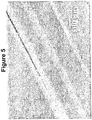
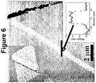
- the method of the invention makes it possible not only to obtain isolated graphene planes, as discussed above, but also graphene ribbons, as highlighted on the graphene ribbons. figures 5 and 6 .
- These ribbons can be 20 to 100 microns long and ⁇ 1 micron wide. For example, ribbons ⁇ 500 nm, ⁇ 100 nm, ⁇ 50 nm, and even ⁇ 10 nm wide can be obtained.
- These ribbons, as well as carbon nanotubes and graphene planes can find applications in the field of electronics or optoelectronics, particularly ribbons ⁇ 10 nm wide. (See Hongjie Dai et al., Science, 319: 1229-1232 (2008) ) [ref 45]).
- the figure 5 represents an atomic force microscopy (AFM) image of a graphene deposit obtained by dipping a solution of reduced graphene in the NMP on an Si / SiO 2 ("Si / SiO 2 wafer") substrate according to US Pat.
- AFM atomic force microscopy
- the reduced graphene solution was obtained from expanded graphite according to the process of the invention.
- the figure 6 represents an atomic force microscopy (AFM) image of a graphene deposit obtained by dipping a reduced graphene solution in NMP on nickel-modified surface mica (see Example 5).
- the reduced graphene solution was obtained from expanded graphite according to the method of the invention.
- the entire object could be followed over its length which is about 40 microns. It is noted that the measured height of this graphene ribbon deposited on mica is approximately 0.4 nm, which is of the order of the theoretical thickness of a graphene plane.
- a graphene plane, isolated in a symmetric environment such as a solution, is intrinsically unstable.
- symmetric environment is meant that the two faces of the graphene plane are “equivalent” in that they "see” the same thing.
- a plane of graphene deposited on a substrate has two unequal faces: one is in contact with the substrate, the other is in contact with the fluid (gas or solution) above or with the vacuum if the together is under vacuum.
- the negative charges on the graphene planes prevent the winding of the planes on themselves, because of the electrostatic repulsions.
- the graphene solutions obtainable by the process of the present invention are stable. The scientific and industrial community will therefore have with these solutions, no longer a few isolated planes on a surface, but an unlimited amount of graphene planes dissolved in a suitable solvent (eg NMP).
- the method of the present invention therefore very advantageously leads to the obtaining, to our knowledge for the first time, of true solutions of isolated graphene planes and / or isolated graphene ribbons.
- graphene like carbon nanotubes, has extraordinary properties (in terms of thermal and electrical conductivities, as well as mechanical properties). From an electrical point of view, electricity flows very quickly in graphene. So besides the gain in terms of space, it could also induce a gain in terms of reactivity of the transistors. Thus, if the graphene transistors are coupled to carbon nanotube interconnections, the field of computing will derive remarkable benefits.
- the reoxidation of the graphene planes obtained by the method of the invention leads to carbon nanotubes multifeuillets type "nanoscrolls" (spirally wound).
- nanostroll nanotubes nanotubes there is today a major effort of synthesis (Arkema, Bayer, Thomas Swan Inc., Nanocyl, etc. .).
- the graphene solutions described in the present application would offer a quality alternative (without impurities) and low cost, allowing the development of large volume applications concerning the multiwall carbon nanotubes.
- the graphene solutions, and / or graphene monoliles, obtained according to the process of the invention can be used in composite materials, hydrogen cells, supercapacitors, sensors, catalysis, NEMS ("nanoelectrochemical systems") and nano-sized electronic components / systems.
- Nanostructural materials such as carbon nanotubes
- One of the objectives of composite materials is to develop very strong and very lightweight materials, which can replace steel ( Dai, L .; Mau, AWH “Controlled Synthesis Of Modification Of Carbon Nanotubes And C60: Carbon Nanostructures For Advanced Polymeric Composite Materials", Adv. Mater., 13, pp. 899-913 (2001) ) [ref 38]).
- the weak point of any composite material is the polymer matrix itself.
- the basic idea of composite materials is to consolidate the polymer matrix, while maintaining its ultra-lightweight material properties. Impregnation of the polymer matrix with a nanomaterial makes it possible to transfer the charge of the matrix to the nanomaterial ( Calvert, P. "A Recipe For Strength".
- the Naph - K + solution was cooled to room temperature, and filtered to remove any traces of solid potassium from the solution.
- the reduced graphene solution in the NMP was red, then turned yellow in contact with the air.
- Example 2 Conditions and protocols similar to those of Example 1 are used, with the difference that the starting graphite is HOPG (Highly oriented pyrolytic graphite).
- HOPG Highly oriented pyrolytic graphite
- Example 3 Preparation of a solution of a potassium salt of graphene from micron graphite obtained by mechanical wear
- Example 2 Conditions and protocols similar to those of Example 1 are used, with the difference that the starting graphite is micron-sized graphite obtained by mechanical wear (e.g., by filing a graphite electrode).
- Example 1 Conditions and protocols similar to those of Example 1 are used, with the difference that the starting graphite is natural graphite (from the company Nacional de Grafite in Brazil).
- the ternary compound obtained in a) above was dissolved in NMP (ca. 0.5 mg / ml) under an inert atmosphere at room temperature with stirring. After 24 hours, the solution was centrifuged at 4000 rpm for 60 minutes to separate the non-soluble material from the graphite salt solution. The colored upper phase represents the reduced graphene solution in NMP. This solution became colorless after exposure with air.
- AAS atomic absorption spectrometer
- the graphene sample was deposited by dipping ("dip-coating") on a piece of freshly cleaved muscovite mica of uniform thickness less than 4 mm, which piece of muscovite mica was previously covered a 45 nm thick silver layer (Sigma-Aldrich 99.9999%) by thermal evaporation.
- the mica surface was immersed for 30 minutes in a 100 mM aqueous solution of NiCl 2 and then dried in order to promote the ionic exchange of Ni 2+ ions with the ions. potassium on the exfoliated surfaces of the reduced graphene layers, thus positively polarizing the mica surface.
- the mica-graphene deposit was then covered with a second semi-reflective layer of silver by thermal evaporation. AFM .
- the deposits were made in the same manner as below, omitting the steps of depositing the silver layers, and were visualized on a multimode AFM microscope (Veeco) in intermittent contact mode ("tapping mode").
- Tunneling microscopy The deposits were made on freshly cleaved HOPG, by deposition and drying of a drop (drop-casting). The surface of the HOPG substrate was visualized just before the deposit to ensure its quality and cleanliness. Low and high resolution images were obtained on Nanoscope instruments III and II, respectively.
- Optical microscopy The deposits were prepared by dipping on Si / SiO 2 special wafers ("Surfs", Nanolane, France).
- a solution of reduced graphene in NMP was obtained according to the experimental protocol described in a) and b) of Example 5.
- Graphene deposits were then carried out by dipping ("dip-coating") or deposition and drying a drop-casting drop of the reduced graphene solution on a MoS 2 support.
Landscapes
- Chemical & Material Sciences (AREA)
- Engineering & Computer Science (AREA)
- Nanotechnology (AREA)
- Organic Chemistry (AREA)
- Materials Engineering (AREA)
- Inorganic Chemistry (AREA)
- General Physics & Mathematics (AREA)
- Physics & Mathematics (AREA)
- Condensed Matter Physics & Semiconductors (AREA)
- Crystallography & Structural Chemistry (AREA)
- Composite Materials (AREA)
- Manufacturing & Machinery (AREA)
- General Life Sciences & Earth Sciences (AREA)
- Geology (AREA)
- Life Sciences & Earth Sciences (AREA)
- Carbon And Carbon Compounds (AREA)
Description
La présente invention se rapporte à un procédé de solubilisation de graphite intercalé et ses applications, notamment pour la fabrication de composites et la purification du graphène.The present invention relates to a process for solubilizing intercalated graphite and its applications, in particular for the manufacture of composites and the purification of graphene.
La présente invention se rapporte en particulier à des solutions de graphène et plans de graphènes obtenus par ledit procédé, ainsi qu'à des utilisations de ces solutions et plans de graphène.The present invention relates in particular to graphene solutions and graphene planes obtained by said method, as well as to uses of these solutions and graphene planes.
L'obtention de graphène sous forme de solutions présente un grand intérêt pour leurs applications industrielles, en particulier pour leur mise en forme en vue d'une utilisation donnée. De telles solutions sont en effet facilement utilisables pour déposer des plans de graphène sur un substrat donné, pour former des films de graphène, ou pour élaborer, par imprégnation, des composites renfermant du graphène. Ces solutions ouvrent également la voie à la purification du graphène.Obtaining graphene in the form of solutions is of great interest for their industrial applications, in particular for shaping them for a given use. Such solutions are indeed easily used to deposit graphene planes on a given substrate, to form graphene films, or to develop, by impregnation, composites containing graphene. These solutions also open the way for the purification of graphene.
Dans la description ci-dessous, les références entre crochets ([]) renvoient à la liste des références présentée après les exemples.In the description below, references in brackets ([]) refer to the list of references after the examples.
Le carbone est connu pour avoir quatre structures ou familles de structures cristallines uniques : le diamant, le graphite, les fullerènes et les nanotubes de carbone.Carbon is known to have four structures or families of unique crystalline structures: diamond, graphite, fullerenes and carbon nanotubes.
La structure tubulaire des nanotubes de carbone leur confère des propriétés mécaniques, électriques et chimiques uniques. À ce titre, ils sont couramment utilisés dans les matériaux composites (
Cependant, le coût relativement élevé des nanotubes de carbone a freiné considérablement leur utilisation à l'échelle industrielle.En effet, la préparation des nanotubes de carbone s'effectue à l'heure actuelle selon trois procédés : par arc électrique à haute température, par ablation laser, et par des procédés de décomposition catalytique. La méthode par arc électrique utilise deux électrodes en graphite entre lesquelles un arc électrique est établi, l'anode se consume pour former un plasma dont la température peut atteindre 6000°C (
Ainsi, la communauté scientifique a développé un intérêt pour un nanomatériau de carbone alternatif qui a des propriétés comparables, mais qui est plus facilement accessible et à moindre coût : le graphène.Thus, the scientific community has developed an interest in an alternative carbon nanomaterial that has comparable properties, but is more easily accessible and cheaper: graphene.
Le graphène ou plan de base du graphite, longtemps considéré comme un objet virtuel, a récemment acquis une existence réelle depuis les travaux de Novoselov et al. (
Le graphite est connu pour conduire à des composés d'intercalation (graphite intercalation compounds GIC) avec soit des donneurs soit des accepteurs d'électrons. (
Depuis 2004 et la publication de Novesolov et coll., le monde de la physique se passionne pour les propriétés électroniques du graphène ou plan isolé de graphite (Electric field effect in atomically thin carbon films,
Cependant, il n'existe actuellement aucune méthode de solubilisation du graphite, et les solutions de graphène en tant que telles restent à ce jour encore élusives.However, there is currently no method for solubilizing graphite, and graphene solutions as such remain to this day still elusive.
Quelques tentatives de solubilisation ont été rapportées , principalement par fonctionnalisation du graphite (
Ces méthodes présentent toutefois l'inconvénient que les plans de graphite obtenus sont fonctionnalisés et dénaturés.These methods, however, have the disadvantage that the graphite planes obtained are functionalized and denatured.
Il existe donc un réel besoin d'un procédé de solubilisation du graphite palliant ces défauts, inconvénients et obstacles de l'art antérieur, en particulier d'un procédé permettant d'obtenir des solutions de graphène facilement utilisables pour la mise en forme du graphène pour une utilisation donnée, de réduire les coûts de fabrication de matériaux composites et d'améliorer l'accessibilité du graphène en grande quantité et de pureté élevée.There is therefore a real need for a method for solubilizing graphite overcoming these defects, disadvantages and obstacles of the prior art, in particular a method making it possible to obtain graphene solutions that can be easily used for shaping graphene. for a given use, to reduce the manufacturing costs of composite materials and to improve the accessibility of graphene in large quantities and high purity.
La présente invention a précisément pour but de répondre à ce besoin en fournissant un procédé de solubilisation du graphite caractérisé en ce qu'il comprend les étapes suivantes réalisées sous atmosphère inerte:
- a) Réduction du graphite par un métal alcalin pour conduire à un composé d'intercalation du graphite; et
- b) Exposition dudit composé d'intercalation du graphite à un solvant polaire aprotique pour conduire à une solution de graphène réduit.
- a) reduction of graphite by an alkali metal to yield a graphite intercalation compound; and
- b) Exposing said graphite intercalation compound to an aprotic polar solvent to yield a reduced graphene solution.
Selon l'invention, le métal alcalin peut être tout métal alcalin permettant de mettre en oeuvre la présente invention. Il peut être choisi par exemple dans le groupe comprenant le lithium, le sodium, le potassium, le rubidium et le césium. Plus particulièrement, le métal alcalin peut être le lithium, le sodium ou le potassium. De préférence, le métal alcalin est le potassium.According to the invention, the alkali metal may be any alkali metal for carrying out the present invention. It may be chosen for example from the group comprising lithium, sodium, potassium, rubidium and cesium. More particularly, the alkali metal may be lithium, sodium or potassium. Preferably, the alkali metal is potassium.
Par « réduction par un métal alcalin» on entend dans la présente une réduction dans laquelle un métal alcalin est impliqué. Ainsi, la réduction peut se faire directement en présence d'un métal alcalin, par exemple en phase vapeur. Des méthodes de réduction en présence d'un métal alcalin sont bien connues dans l'art. L'homme du métier saura identifier les conditions opératoires adéquates pour mettre en oeuvre un procédé de réduction en présence d'un métal alcalin, par exemple en phase vapeur. Notamment, l'homme du métier pourra s'inspirer des méthodes décrites dans « Synthesis of graphite intercalation compounds », A. Hérold in Chemical physics of intercalation,
Dans un autre mode de réalisation, la réduction se fait en présence d'un sel de métal alcalin obtenu à partir d'un métal alcalin. Par exemple, la réduction peut se faire en présence d'un sel polyaryl alcalin de formule A+B-, dans laquelle A+ représente un cation d'un ion alcalin, et B- représente un anion d'un composé polyaromatique.De tels sels polyaryl alcalin et leur procédé de fabrication sont décrits par exemple dans (
Selon un mode de réalisation, le composé polyaromatique est choisi dans le groupe comprenant le naphtalène, la benzophénone, la fluorénone, la benzoquinone et l'anthraquinone. Dans un mode de réalisation particulier, le composé polyaromatique est le naphtalène. Dans un mode de réalisation particulier, le sel polyaryl alcalin est un sel polyaryl de potassium (c'est-à-dire, un sel de formule A+B-, dans laquelle A+ représente K+). Avantageusement, le sel polyaryl alcalin de formule A+B-, est un sel de potassium de naphthalene (Naph- K+).According to one embodiment, the polyaromatic compound is selected from the group consisting of naphthalene, benzophenone, fluorenone, benzoquinone and anthraquinone. In a particular embodiment, the polyaromatic compound is naphthalene. In a particular embodiment, the alkali polyaryl salt is a polyaryl potassium salt (i.e., a salt of formula A + B - , wherein A + is K + ). Advantageously, the alkali polyaryl salt of formula A + B - is a potassium salt of naphthalene (Naph - K + ).
Dans un autre mode de réalisation, la réduction se fait par électrochimie où le graphite est utilisé comme cathode et le métal alcalin se présente sous la forme d'un sel d'alcalin. La réduction électrochimique du graphite est accompagnée de l'insertion des ions alcalins présents dans la solution.In another embodiment, the reduction is by electrochemistry where the graphite is used as a cathode and the alkali metal is in the form of an alkaline salt. The electrochemical reduction of the graphite is accompanied by the insertion of the alkaline ions present in the solution.
Par « composé d'intercalation du graphite» ou « GIC » pour « Graphite Intercalation Compound » on entend dans la présente un composé comprenant au moins deux plans individuels de graphène chargés négativement ou positivement et intercalés par des contre ions positifs ou négatifs. Les sels d'alcalins de graphite sont un cas particulier de GIC ou les plans de graphène sont chargés négativement et les contre-ions sont des ions alcalins. Le GIC peut se présenter sous la forme d'un composé binaire de formule MCx où M représente un contre-ion positif d'un métal alcalin (M+), et x représente un nombre entier compris entre 6 et 200. En particulier, le métal alcalin peut être le potassium. Par exemple, le GIC peut être un composé binaire de formule KC8.By "graphite intercalation compound" or "GIC" for "Graphite Intercalation Compound" is meant herein a compound comprising at least two individual planes of graphene negatively or positively charged and intercalated by positive or negative counter ions. Graphite alkali salts are a special case of GIC where the graphene planes are negatively charged and the counterions are ions. alkali. The GIC may be in the form of a binary compound of formula MC x where M represents a positive counterion of an alkali metal (M + ), and x represents an integer between 6 and 200. In particular, the alkali metal may be potassium. For example, the ICG may be a binary compound of formula KC 8 .
Dans un autre mode de réalisation, Le GIC peut se présenter sous la forme d'un composé ternaire de formule M(Solv)yCx dans laquelle M est un ion métallique alcalin (M+), Solv est une molécule de solvant aprotique, x représente un nombre entier compris entre 6 et 200, et y représente un nombre entier compris entre 0 et 4. La molécule de solvant peut être une molécule d'un solvant aromatique (par exemple le benzène ou le toluène) ou nucléophile (par exemple, un solvant dont la structure contient au moins un atome d'oxygène comme le THF). Par exemple, le GIC peut être un composé ternaire de formule K(THF)C24 ou K(THF)2C24.In another embodiment, the GIC may be in the form of a ternary compound of formula M (Solv) y C x in which M is an alkali metal ion (M + ), Solv is an aprotic solvent molecule, x represents an integer between 6 and 200, and y represents an integer between 0 and 4. The solvent molecule may be a molecule of an aromatic solvent (for example benzene or toluene) or nucleophilic (for example a solvent whose structure contains at least one oxygen atom such as THF). For example, the GIC may be a ternary compound of formula K (THF) C 24 or K (THF) 2 C 24 .
Par «graphène réduit», on entend dans la présente un ou plusieurs plans de graphène individuel(s) chargé(s) négativement. La charge négative est délocalisée sur les atomes de carbone formant le plan de graphène.By "reduced graphene" is meant herein one or more graphene planes individually (s) negatively charged. The negative charge is delocalized on the carbon atoms forming the graphene plane.
Selon un mode de réalisation particulier, l'étape de réduction a) se fait en présence d'un solvant. Par exemple, le solvant peut être un solvant nucléophile. Par exemple, le solvant nucléophile peut être un solvant aprotique dont la structure contient au moins un atome d'oxygène, en particulier le THF.According to a particular embodiment, the reduction step a) is in the presence of a solvent. For example, the solvent may be a nucleophilic solvent. For example, the nucleophilic solvent may be an aprotic solvent whose structure contains at least one oxygen atom, in particular THF.
Selon un mode de réalisation particulier, le composé d'intercalation du graphite se présente sous la forme d'un composé binaire de formule MCx où M représente un contre-ion positif d'un métal alcalin (M+), et x représente un nombre entier compris entre 6 et 200. En particulier, le métal alcalin peut être le potassium. Par exemple, le composé d'intercalation du graphite peut être un composé binaire de formule KC8.According to a particular embodiment, the intercalation compound of graphite is in the form of a binary compound of formula MC x where M represents a positive counterion of an alkali metal (M + ), and x represents a an integer between 6 and 200. In particular, the alkali metal may be potassium. For example, the intercalation compound of graphite may be a binary compound of formula KC 8 .
Selon un mode de réalisation particulier, le composé d'intercalation du graphite se présente sous la forme d'un composé ternaire de structure M(Solv)yCx dans laquelle M est un ion métallique alcalin, Solv est un solvant nucléophile dont la structure contient au moins un atome d'oxygène, x représente un nombre entier compris entre 6 et 200, et y représente un nombre entier compris entre 0 et 4. En particulier, le métal alcalin est le potassium, le solvant est le THF et le composé d'intercalation du graphite est un composé ternaire de structure K(THF)yCx dans laquelle x représente un nombre entier compris entre 6 et 200, et y représente un nombre entier compris entre 0 et 4. Dans un mode de réalisation particulier, le composé d'intercalation du graphite est un composé ternaire de structure K(THF)C24 ou K(THF)2C24.According to a particular embodiment, the intercalation compound of the graphite is in the form of a ternary compound of structure M (Solv) y C x in which M is an alkaline metal ion, Solv is a nucleophilic solvent whose structure contains at least one oxygen atom, x represents an integer between 6 and 200, and y represents an integer between 0 and 4. In particular, the alkali metal is potassium, the solvent is THF and the intercalation compound of graphite is a ternary compound of structure K (THF) y C x wherein x represents an integer between 6 and 200, and y represents an integer between 0 and 4. In a particular embodiment, the graphite intercalation compound is a compound ternary structure K (THF) C 24 or K (THF) 2 C 24 .
Selon un mode de réalisation particulier, l'étape de réduction est choisie dans le groupe comprenant la réduction par un métal alcalin en phase vapeur suivie d'une exposition à un solvant aprotique, la réduction électrochimique et la réduction par un sel polyaryl alcalin dans un solvant aprotique. Par exemple, le solvant peut être un solvant aromatique, tel que le benzène ou le toluène. Le solvant peut être un solvant aprotique dont la structure contient au moins un atome d'oxygène comme le THF.According to a particular embodiment, the reduction step is selected from the group consisting of vapor phase alkali metal reduction followed by exposure to an aprotic solvent, electrochemical reduction and alkali polyaryl salt reduction in a aprotic solvent. For example, the solvent may be an aromatic solvent, such as benzene or toluene. The solvent can be an aprotic solvent whose structure contains at least one oxygen atom such as THF.
Selon un mode de réalisation particulier, l'étape de réduction a) comprend l'addition au graphite, sous atmosphère inerte, d'un sel polyaryl alcalin de formule A+B-, dans laquelle :
- A+ représente un cation d'un ion alcalin, et
- B- représente un anion d'un composé polyaromatique.
- A + represents a cation of an alkaline ion, and
- B - represents an anion of a polyaromatic compound.
Selon un mode de réalisation, le composé polyaromatique est choisi dans le groupe comprenant le naphtalène, la benzophénone, la fluorénone, la benzoquinone et l'anthraquinone. Le solvant polaire aprotique utilisé dans l'étape de mélange b) a une constante diélectrique de 25 à 200.According to one embodiment, the polyaromatic compound is selected from the group consisting of naphthalene, benzophenone, fluorenone, benzoquinone and anthraquinone. The aprotic polar solvent used in the mixing step b) has a dielectric constant of 25 to 200.
Le solvant polaire aprotique utilisé dans l'étape de mélange b) peut répondre à la structure (I) suivante:

X représente O ou S :
- R1 représente H, un groupe alkyle en C1 à C6 ou alkenyle en C2 à C6 linéaire ou ramifié, ou un groupe cycloalkyle en C3 à C6 ou cycloalkenyle en C5 à C6; et
- R2 représente H, un halogène, un groupe alkyle en C1 à C6 ou alkenyle en C2 à C6 linéaire ou ramifié, un groupe cycloalkyle en C3 à C6 ou cycloalkenyle en C5 à C6, ou un groupe -OR dans lequel R représente un groupe alkyle en C1 à C6 ou alkenyle en C2 à C6 linéaire ou ramifié, un groupe cycloalkyle en C3 à C6 ou cycloalkenyle en C5 à C6 .
X represents O or S:
- R 1 represents H, a C 1 to C 6 alkyl group or a C 2 to C 6 linear or branched alkenyl group, or a C 3 to C 6 cycloalkyl or C 5 to C 6 cycloalkenyl group; and
- R 2 is H, halogen, C 1 to C 6 alkyl or C 2 to C 6 straight or branched alkenyl, C 3 to C 6 cycloalkyl or C 5 to C 6 cycloalkenyl, or a group -OR wherein R is C 1 -C 6 alkyl or C 2 -C 6 linear or branched alkenyl, C 3 -C 6 cycloalkyl or C 5 -C 6 cycloalkenyl.
Avantageusement, dans le solvant polaire aprotique de formule (I), R1 représente un groupe alkyle en C1 à C6 ou alkenyle en C2 à C6 linéaire ou ramifié, ou un groupe cycloalkyle en C3 à C6 ou cycloalkenyle en C5 à C6.Advantageously, in the aprotic polar solvent of formula (I), R 1 represents a C 1 to C 6 alkyl or linear or branched C 2 to C 6 alkenyl group, or a C 3 to C 6 cycloalkyl or cycloalkenyl group. C 5 to C 6 .
Le solvant polaire aprotique utilisé dans l'étape de mélange b) peut répondre à la structure (IA) :

Avantageusement, dans le solvant polaire aprotique de formule (IA), R1 représente un groupe alkyle en C1 à C6 ou alkenyle en C2 à C6 linéaire ou ramifié, ou un groupe cycloalkyle en C3 à C6 ou cycloalkenyle en C5 à C6.Advantageously, in the aprotic polar solvent of formula (I A ), R 1 represents a C 1 to C 6 alkyl or linear or branched C 2 to C 6 alkenyl group, or a C 3 to C 6 cycloalkyl or cycloalkenyl group. in C 5 to C 6 .
Avantageusement, dans le solvant polaire aprotique de formule (IA) :
- X représente O ou S; et/ou
- R1 représente un groupe alkyle en C1 à C4 ou alkenyle en C2 à C3 linéaire ou ramifié, ou un groupe cycloalkyle en C5 à C6 ou cycloalkenyle en C5 à C6; et/ou
- m est 1 ; et/ou
- R2 représente H, un halogène, ou un groupe alkyle en C1 à C4 linéaire ou ramifié.
- X is O or S; and or
- R 1 represents an alkyl group C 1 -C 4 alkenyl or C 2 -C 3 linear or branched, or cycloalkyl C 5 -C 6 cycloalkyl or C 5 -C 6; and or
- m is 1; and or
- R 2 represents H, a halogen, or a linear or branched C 1 -C 4 alkyl group.
Par exemple, dans le solvant polaire aprotique de formule (IA), R1 représente méthyle, éthyle, n-propyle, vinyle ou cyclohexyle.For example, in the aprotic polar solvent of formula (I A ), R 1 represents methyl, ethyl, n-propyl, vinyl or cyclohexyl.
Par exemple, le solvant polaire aprotique répond à la formule suivante :

Par exemple, dans le solvant polaire aprotique de formule (IA) X représente O et le solvant polaire aprotique utilisé dans l'étape b) est la N-méthyl-2-pyrrolidinone (NMP), la N-éthyl-2-pyrrolidinone, la N-cyclohexyl-2-pyrrolidinone ou la N-vinyl-2-pyrrolidinone.For example, in the aprotic polar solvent of formula (I A ) X is O and the aprotic polar solvent used in step b) is N-methyl-2-pyrrolidinone (NMP), N-ethyl-2-pyrrolidinone N-cyclohexyl-2-pyrrolidinone or N-vinyl-2-pyrrolidinone.
Selon un mode de réalisation, dans le solvant polaire aprotique de formule (IA) X représente S et le solvant polaire aprotique utilisé dans l'étape b) est la N-méthyl-2-pyrrolidinethione, la N-éthyl-2-pyrrolidinethione, la N-cyclohexyl-2-pyrrolidinethione ou la N-vinyl-2-pyrrolidinethione.According to one embodiment, in the aprotic polar solvent of formula (I A ) X represents S and the aprotic polar solvent used in step b) is N-methyl-2-pyrrolidinethione, N-ethyl-2-pyrrolidinethione N-cyclohexyl-2-pyrrolidinethione or N-vinyl-2-pyrrolidinethione.
Le solvant polaire aprotique utilisé dans l'étape de mélange b) peut répondre à la structure (IB) :

X représente O ou S :
- R1 représente H, un groupe alkyle en C1 à C6 ou alkenyle en C2 à C6 linéaire ou ramifié, ou un groupe cycloalkyle en C3 à C6 ou cycloalkenyle en C5 à C6; et
- R2 représente H, un halogène, un groupe alkyle en C1 à C6 ou alkenyle en C2 à C6 linéaire ou ramifié, un groupe cycloalkyle en C3 à C6 ou cycloalkenyle en C5 à C6, ou un groupe -OR dans lequel R représente un groupe alkyle en C1 à C6 ou alkenyle en C2 à C6 linéaire ou ramifié, un groupe cycloalkyle en C3 à C6 ou cycloalkenyle en C5 à C6.
X represents O or S:
- R 1 represents H, a C 1 to C 6 alkyl group or a C 2 to C 6 linear or branched alkenyl group, or a C 3 to C 6 cycloalkyl or C 5 to C 6 cycloalkenyl group; and
- R 2 is H, halogen, C 1 to C 6 alkyl or C 2 to C 6 straight or branched alkenyl, C 3 to C 6 cycloalkyl or C 5 to C 6 cycloalkenyl, or a group -OR wherein R is C 1 -C 6 alkyl or C 2 -C 6 linear or branched alkenyl, C 3 -C 6 cycloalkyl or C 5 -C 6 cycloalkenyl.
Avantageusement, dans le solvant polaire aprotique de formule (IB), R1 représente un groupe alkyle en C1 à C6 ou alkenyle en C2 à C6 linéaire ou ramifié, ou un groupe cycloalkyle en C3 à C6 ou cycloalkenyle en C5 à C6.Advantageously, in the aprotic polar solvent of formula (I B ), R 1 represents a C 1 to C 6 alkyl or linear or branched C 2 to C 6 alkenyl group, or a C 3 to C 6 cycloalkyl or cycloalkenyl group. in C 5 to C 6 .
Avantageusement, dans le solvant polaire aprotique de formule (IB) :
- X représente O ou S; et/ou
- R1 représente un groupe alkyle en C1 à C4 ou alkenyle en C2 à C3 linéaire ou ramifié, ou un groupe cycloalkyle en C5 à C6 ou cycloalkenyle en C5 à C6; et/ou
- m est 1 ; et/ou
- R2 représente H, un halogène, ou un groupe alkyle en C1 à C4 linéaire ou ramifié.
- X is O or S; and or
- R 1 represents an alkyl group C 1 -C 4 alkenyl or C 2 -C 3 linear or branched, or cycloalkyl C 5 -C 6 cycloalkyl or C 5 -C 6; and or
- m is 1; and or
- R 2 represents H, a halogen, or a linear or branched C 1 -C 4 alkyl group.
Par exemple, dans le solvant polaire aprotique de formule (IB), R1 représente méthyle, éthyle, n-propyle, vinyle ou cyclohexyle.For example, in the aprotic polar solvent of formula (I B ), R 1 represents methyl, ethyl, n-propyl, vinyl or cyclohexyl.
Par exemple, lé solvant polaire aprotique répond à l'une des formules suivantes :

Par exemple, dans le solvant polaire aprotique de formule (IB), X représente O et le solvant polaire aprotique utilisé dans l'étape b) est la N-méthyl-2-piperidinone, la 1,3-diméthyl-2-piperidinone, la 1,5-diméthyl-2-piperidinone, la N-éthyl-2-piperidinone, la N-propyl-2-piperidinone, la N-cyclohexyl-2-piperidinone ou la N-vinyl-2-piperidinone.For example, in the aprotic polar solvent of formula (I B ), X is O and the aprotic polar solvent used in step b) is N-methyl-2-piperidinone, 1,3-dimethyl-2-piperidinone 1,5-dimethyl-2-piperidinone, N-ethyl-2-piperidinone, N-propyl-2-piperidinone, N-cyclohexyl-2-piperidinone or N-vinyl-2-piperidinone.
Selon un mode de réalisation, dans le solvant polaire aprotique de formule (IB), X représente S et le solvant polaire aprotique utilisé dans l'étape b) est la N-méthyl-2-piperidinethione, la 1,3-diméthyl-2-piperidinethione, la 1,5-diméthyl-2-piperidinethione, la N-éthyl-2-piperidinethione, la N-propyl-2-piperidinethione, la N-cyclohexyl-2-piperidinethione ou la N-vinyl-2-piperidinethione.According to one embodiment, in the aprotic polar solvent of formula (I B ), X is S and the aprotic polar solvent used in step b) is N-methyl-2-piperidinethione, 1,3-dimethyl- 2-piperidinethione, 1,5-dimethyl-2-piperidinethione, N-ethyl-2-piperidinethione, N-propyl-2-piperidinethione, N-cyclohexyl-2-piperidinethione or N-vinyl-2-piperidinethione .
Par exemple, le solvant polaire aprotique peut être la N-méthylpyrrolidone ou le sulfolane. Dans un mode de réalisation particulier, le solvant polaire aprotique est la N-méthylpyrrolidone (NMP).For example, the aprotic polar solvent may be N-methylpyrrolidone or sulfolane. In a particular embodiment, the aprotic polar solvent is N-methylpyrrolidone (NMP).
Dans ce document, les termes « N-méthylpyrrolidone », « N-méthyl-2-pyrrolidone » et « NMP» sont interchangeables et désignent tous le même solvant de formule :

Selon un mode de réalisation particulier, l'étape de mélange b) est effectuée à une température de -22 à 202 °C. Par exemple, l'étape de mélange b) est effectuée à une température de 20 à 25°C.According to a particular embodiment, the mixing step b) is carried out at a temperature of -22 to 202 ° C. For example, the mixing step b) is carried out at a temperature of 20 to 25 ° C.
D'une manière générale, le procédé de l'invention, en particulier l'étape de mélange b), peut être mis en oeuvre avec ou sans agitation. Lorsqu'un système d'agitation est utilisé, il peut s'agir d'un système d'agitation mécanique, magnétique ou par sonication. Dans un mode de réalisation particulier, le procédé est effectué sous agitation mécanique. Dans un autre mode de réalisation, le procédé est effectué sous agitation magnétique.In general, the process of the invention, in particular the mixing step b), can be carried out with or without stirring. When a stirring system is used, it may be a mechanical stirring system, magnetic or sonication. In a particular embodiment, the process is carried out with mechanical stirring. In another embodiment, the process is carried out with magnetic stirring.
Il est à noter que bien que le procédé de l'invention puisse être mis en oeuvre avec un système d'agitation comprenant la sonication, celle-ci n'est nullement nécessaire. D'ailleurs, un avantage notable du présent procédé est qu'il repose sur une méthode de dissolution douce, à partir de graphite neutre, qui donne précisément la possibilité d'éviter tout recours à la sonication. Ainsi, le procédé de l'invention permet d'obtenir des plans de graphène de grande taille.It should be noted that although the method of the invention can be implemented with a stirring system comprising sonication, this is not necessary. Moreover, a significant advantage of the present method is that it relies on a gentle dissolution method, from neutral graphite, which gives precisely the possibility of avoiding any recourse to sonication. Thus, the method of the invention makes it possible to obtain graphene planes of large size.
Selon un mode particulier de mise en oeuvre du procédé de la présente invention, on peut appliquer après l'étape (a) et avant l'étape (b), une étape (a1) de filtration. Par exemple, lorsque l'étape (a) du procédé implique une réduction en présence d'un sel de métal alcalin obtenu à partir d'un métal alcalin, la filtration peut permettre de séparer la phase liquide (par exemple une solution de K+Napht- dans du THF) de la phase solide comprenant le composé d'intercalation du graphite et éventuellement du graphite non réduit. Le graphite intercalé avec un métal alcalin ainsi obtenu peut être rincé une ou plusieurs fois avec un solvant adéquat. Par exemple, après l'étape de filtration (a1), le composé d'intercalation du graphite peut être rincé avec le même solvant utilisé lors de l'étape (a), notamment le THF. Le composé d'intercalation du graphite ainsi rincé peut être éventuellement séché avant l'étape (b).According to a particular embodiment of the process of the present invention, a step (a1) of filtration can be applied after step (a) and before step (b). For example, when step (a) of the process involves a reduction in the presence of an alkali metal salt obtained from an alkali metal, the filtration can make it possible to separate the liquid phase (for example a solution of K + Naphth- in THF) of the solid phase comprising the intercalation compound of graphite and possibly unreduced graphite. The graphite intercalated with an alkali metal thus obtained can be rinsed one or more times with a suitable solvent. For example, after the filtration step (a1), the intercalation compound of the graphite can be rinsed with the same solvent used in step (a), especially THF. The intercalation compound of the graphite thus rinsed may be optionally dried before step (b).
Selon un mode de réalisation particulier, le procédé comprend en outre une étape de centrifugation (b1), celle-ci permettant de séparer toute fraction non dissoute de la solution de graphène réduit après l'étape (b). L'homme du métier saura déterminer les conditions de centrifugation adéquates pour obtenir une solution de graphène réduit limpide, c'est-à-dire ne comprenant pas d'agrégats détectables. Par exemple, la centrifugation peut être effectuée entre 100 et 200000 g , pendant 0.1 à 24 heures. Dans un mode de réalisation particulier, l'étape de centrifugation est effectuée à 2800 g pendant 1 heure.According to a particular embodiment, the method further comprises a centrifugation step (b1), which makes it possible to separate any undissolved fraction from the reduced graphene solution after step (b). Those skilled in the art will be able to determine the appropriate centrifugation conditions to obtain a clear reduced graphene solution, that is to say not comprising detectable aggregates. For example, the centrifugation can be carried out between 100 and 200000 g for 0.1 to 24 hours. In a particular embodiment, the centrifugation step is carried out at 2800 g for 1 hour.
Selon un mode de réalisation, la présence d'agrégats dans la solution au cours de la centrifugation est vérifiée à l'oeil nu. Ainsi, un échantillon de la solution peut être prélevé à différents intervalles dans l'étape de centrifugation pour déterminer lorsque celle-ci aura permis d'obtenir une solution limpide (c'est-à-dire sans agrégats visibles à l'oeil nu). L'examen à l'oeil nu permet de détecter des agrégats éventuels ayant une taille minimale de l'ordre du 10ième de millimètre (100 microns).According to one embodiment, the presence of aggregates in the solution during the centrifugation is checked with the naked eye. Thus, a sample of the solution can be taken at different intervals in the centrifugation step to determine when it has made it possible to obtain a clear solution (that is to say without aggregates visible to the naked eye). . The examination with the naked eye makes it possible to detect possible aggregates having a minimum size of about 10th of a millimeter (100 microns).
Selon un mode de réalisation, la présence d'agrégats dans la solution au cours de la centrifugation est vérifiée par microscope optique. Ainsi, un échantillon de la solution peut être prélevé à différents intervalles dans l'étape de centrifugation pour déterminer lorsque celle-ci aura permis d'obtenir une solution limpide (c'est-à-dire sans agrégats visibles au microscope optique). L'examen au microscope optique permet de détecter des agrégats éventuels ayant une taille minimale de l'ordre du micron. Dans un mode de réalisation particulier, l'échantillon de la solution peut être analysé au microscope optique avec un grossissement de 20 à 100.According to one embodiment, the presence of aggregates in the solution during the centrifugation is verified by optical microscope. Thus, a sample of the solution can be taken at different intervals in the centrifugation step to determine when it has made it possible to obtain a clear solution (that is to say without aggregates visible under an optical microscope). The optical microscope examination allows the detection of possible aggregates with a minimum size of about one micron. In a particular embodiment, the sample of the solution can be analyzed under an optical microscope with a magnification of 20 to 100.
Selon un mode de réalisation particulier, le procédé comprend en outre une étape de dépôt de plans de graphène réduit sur un substrat donné. De préférence, ce dépôt est effectué sous atmosphère inerte. Une fois le dépôt effectué et le solvant éliminé, le substrat peut être exposé à l'air librement : les plans de graphène sont alors en interaction avec la surface et restent stabilisés sur la surface après réoxydation vers l'état neutre (voir
Le dépôt de graphène peut se faire par simple dépôt d'une quantité de solution de graphène sur un substrat, suivi de l'évaporation du solvant polaire aprotique utilisé dans l'étape (b) afin d'isoler les plans de graphène. Par exemple, la solution de graphène réduit de l'invention peut être déposée sur un substrat donné, et le solvant évaporé sous atmosphère inerte. Des plans de graphène déposés sur le substrat peuvent ainsi être obtenus, une fois le solvant polaire aprotique évaporé.The deposition of graphene can be done by simply depositing a quantity of graphene solution on a substrate, followed by the evaporation of the aprotic polar solvent used in step (b) in order to isolate the graphene planes. For example, the reduced graphene solution of the invention may be deposited on a given substrate, and the solvent evaporated under an inert atmosphere. Planes of graphene deposited on the substrate can thus be obtained, once the aprotic polar solvent is evaporated.
Le dépôt de graphène peut également être effectué par dépôt par application, par exemple avec un pinceau ou autre instrument permettant le dépôt d'un film de solution de graphène sur un substrat donné.The deposition of graphene may also be performed by application deposition, for example with a brush or other instrument for depositing a film of graphene solution on a given substrate.
Le dépôt de graphène peut également être effectué par dépôt par trempage (« dip-coating »). Par exemple, le substrat peut être trempé dans la solution de graphène un certain temps afin de permettre l'adsorption des plans de graphène sur la surface du substrat. Le substrat est ensuite retiré de la solution, de préférence à une vitesse uniforme pour obtenir un revêtement uniforme, et le solvant est évaporé.Graphene deposition can also be performed by dip-coating. For example, the substrate may be dipped in the graphene solution for a time to allow adsorption of the graphene planes on the surface of the substrate. The substrate is then removed from the solution, preferably at a uniform rate to obtain a uniform coating, and the solvent is evaporated.
Le dépôt de graphène peut également être mis en oeuvre par dépôt à la tournette (« spin coating »). Par exemple, une goutte de solution de graphène peut être déposée sur un substrat en rotation, éventuellement à haute température. De préférence, la vitesse de rotation est maintenue constante durant le processus de façon à obtenir un dépôt uniforme, et le solvant est évaporé. Lorsque le dépôt à la tournette est effectué à haute température, ladite température peut être entre 10 et 200 °C.The deposit of graphene can also be implemented by spin coating ("spin coating"). For example, a drop of graphene solution may be deposited on a rotating substrate, possibly at high temperature. Preferably, the rotational speed is kept constant during the process so as to obtain a uniform deposit, and the solvent is evaporated. When the spin coating is performed at high temperature, said temperature can be between 10 and 200 ° C.
Le dépôt de graphène peut également être mis en oeuvre par dépôt et séchage d'une goutte de solution (« drop-casting»). Par exemple, une goutte de solution de graphène peut être déposée sur un substrat. La goutte de solvant est ensuite évaporée, éventuellement à une température élévée en fonction du solvant à évaporer.The deposit of graphene can also be implemented by depositing and drying a drop of solution ("drop-casting"). For example, a drop of graphene solution may be deposited on a substrate. The drop of solvent is then evaporated, optionally at an elevated temperature depending on the solvent to be evaporated.
De telles méthodes sont connues de l'homme du métier, qui saura adapter les conditions de mise en oeuvre en fonction des paramètres tels que la nature du substrat, les interactions entre le substrat et les plans de graphène, la mouillabilité du substrat par le solvant, et autres paramètres dont l'homme du métier reconnaîtra la pertinence.Such methods are known to the person skilled in the art, who will be able to adapt the conditions of implementation as a function of the parameters such as the nature of the substrate, the interactions between the substrate and the graphene planes, and the wettability of the substrate by the solvent. and other parameters that the skilled person will recognize the relevance.
Les substrats susceptibles d'être utilisés comprennent de manière non exhaustive les céramiques, les métaux, le verre, la silice, la molybdénite (MoS2), le mica, le graphite et/ou les plastiques. Dans un mode de réalisation, le substrat peut être tout substrat connu, utilisé et/ou adapté pour le dépôt de nanotubes de carbone ou de plans de graphène. Par exemple, le substrat peut être du HOPG (highly oriented pyrolytic graphite), Si/SiO2, mica ou MoS2.Substrates which may be used include, but are not limited to, ceramics, metals, glass, silica, molybdenite (MoS2), mica, graphite and / or plastics. In one embodiment, the substrate may be any known substrate, used and / or adapted for the deposition of carbon nanotubes or graphene planes. For example, the substrate may be HOPG (highly oriented pyrolytic graphite), Si / SiO 2 , mica or MoS 2 .
Dans un mode de réalisation particulier, le substrat peut être fonctionnalisé ou modifié avant dépôt du graphène. En effet, le procédé selon l'invention implique la dissolution d'un composé d'intercalation du graphite obtenu par réduction du graphite par un métal alcalin (étape b)). Ledit composé d'intercalation du graphite est constitué de plans de graphène chargés négativement intercalés par des cations de métal alcalin. Ainsi, le graghène dissous dans un solvant polaire aprotique selon le procédé de l'invention existe sous forme de feuillets chargés négativement. Des interactions électrostatiques peuvent intervenir entre les feuillets de graphène et le substrat lors du dépôt, en fonction de l'état de surface du substrat. En particulier, des interactions défavorables peuvent se produire si le substrat comprend des charges négatives en surface.In a particular embodiment, the substrate may be functionalized or modified before deposition of graphene. Indeed, the method according to the invention involves the dissolution of a graphite intercalation compound obtained by reducing the graphite with an alkali metal (step b)). Said graphite intercalation compound consists of negatively charged graphene planes interposed with alkali metal cations. Thus, the graghene dissolved in an aprotic polar solvent according to the process of the invention exists in the form of negatively charged layers. Electrostatic interactions can occur between the graphene sheets and the substrate during deposition, depending on the surface condition of the substrate. In particular, adverse interactions can occur if the substrate comprises negative surface charges.
Par exemple, la modification de la surface du substrat peut être effectuée en exposant ledit substrat à une solution ionique contenant des cations susceptibles de participer à un échange ionique avec les cations de métal alcalin présents sur les faces exfoliées des feuillets de graphène réduit, et entraînant ainsi une polarisation positive de la surface du substrat lorsque celle-ci est mise en contact avec la solution de graphène réduit obtenue à l'étape b). Par exemple, la surface du substrat peut être modifiée par trempage (« dip-coating ») dans ladite solution ionique. Le substrat peut être ensuite séché pour évaporer le solvant de la solution ionique, avant dépôt de la solution de graphène réduit.For example, the modification of the surface of the substrate can be carried out by exposing said substrate to an ionic solution containing cations capable of participating in ion exchange with the cationic cations. alkaline metal present on the exfoliated surfaces of the reduced graphene layers, and thus causing a positive polarization of the substrate surface when it is brought into contact with the reduced graphene solution obtained in step b). For example, the surface of the substrate may be modified by dipping ("dip-coating") in said ionic solution. The substrate may then be dried to evaporate the solvent from the ionic solution prior to deposition of the reduced graphene solution.
L'homme du métier saura sélectionner les solutions ioniques adéquates pour ce faire, et pourra se référer par exemple à III et al.,
Par exemple, lorsque le métal alcalin de l'étape a) est le potassium, on pourra utiliser une solution aqueuse de NiCl2. Après trempage (« dip-coating ») du substrat dans ladite solution de NiCl2, le substrat peut être séché (par exemple sous vide, éventuellement en élevant la température pour favoriser l'évaporation de l'eau). Ainsi, après dépôt de la solution de graphène réduit, les ions Ni2+ préalablement déposés sur la surface du substrat peuvent participer à un échange ionique avec les ions potassium (K+) présents sur les faces exfoliées des feuillets de graphène réduit obtenu à l'étape b).For example, when the alkali metal of step a) is potassium, an aqueous solution of NiCl 2 can be used . After dipping ("dip-coating") the substrate in said NiCl 2 solution, the substrate may be dried (for example under vacuum, possibly raising the temperature to promote the evaporation of water). Thus, after deposition of the reduced graphene solution, the Ni 2+ ions previously deposited on the surface of the substrate can participate in an ion exchange with the potassium ions (K +) present on the exfoliated surfaces of the reduced graphene sheets obtained at step b).
Le substrat peut également être modifié par dépot d'une couche monomoléculaire d'un composé afin d'obtenir une surface hydrophobe. Par exemple, le substrat (e.g., mica) peut être recouvert d'une couche de polylysine selon des protocoles largement connus de l'homme du métier.The substrate may also be modified by depositing a monomolecular layer of a compound to obtain a hydrophobic surface. For example, the substrate (e.g., mica) may be coated with a polylysine layer according to protocols widely known to those skilled in the art.
D'autres types de modifications de surface des substrats sont également envisageables. En général, on pourra avoir recours à toute méthode de modification de surface connue de l'homme du métier. Le choix du type de modification dépendra de la nature du substrat, du solvant polaire aprotique utilisé pour solubiliser le graphène, et des interactions physicochimiques recherchées au niveau de la surface du substrat pour améliorer la qualité des dépôts de graphène.Other types of surface modifications of the substrates are also conceivable. In general, any method of surface modification known to those skilled in the art may be used. The choice of the type of modification will depend on the nature of the substrate, the aprotic polar solvent used to solubilize graphene, and physicochemical interactions sought at the surface of the substrate to improve the quality of graphene deposits.
Les étapes a) et b) du procédé sont toujours effectuées sous atmosphère inerte. Par « atmosphère inerte », on entend par la présente un gaz ou un mélange gazeux qui ne favorise pas la ré-oxydation des plans de graphène réduit en plans de graphène neutre. Par exemple, le procédé est conduit sous atmosphère gazeuse dépourvue d'oxygène. En particulier, le procédé peut être effectué sous atmosphère d'argon ou d'azote.Steps a) and b) of the process are always carried out under an inert atmosphere. "Inert atmosphere" means here a gas or a gaseous mixture that does not promote the re-oxidation of reduced graphene planes in neutral graphene planes. For example, the process is conducted under gaseous atmosphere without oxygen. In particular, the process can be carried out under an argon or nitrogen atmosphere.
Le procédé décrit dans la présente résout les problèmes majeurs actuels au développement de la recherche dans le domaine du graphène : le manque d'échantillons et les difficultés d'applications.The method described herein solves the current major problems in the development of research in the field of graphene: the lack of samples and the difficulties of applications.
Depuis 2004, le graphène a conduit à de très nombreux travaux du fait de l'intérêt suscité par ses propriétés électroniques. [ref 18, ref 19] La grande majorité de ces travaux, cependant, est théorique du fait de la difficulté à préparer des échantillons. D'autre part, des premières pistes vers des matériaux composites ont été rapportées, par réduction d'oxyde de graphite. (
Les inventeurs de la présente sont les tout premiers à avoir réalisé un procédé de dissolution du graphite. D'un point de vue industriel, il est clair que cette possibilité d'obtenir des solutions de graphène est une donnée importante dans l'industrie des nanotechnologies et des matériaux composites car elle est cruciale pour le bon développement des progrès techniques dans ce domaine.The inventors of the present are the first to have achieved a method of dissolving graphite. From an industrial point of view, it is clear that this possibility of obtaining graphene solutions is an important factor in the nanotechnology and composite materials industry because it is crucial for the good development of technical progress in this field.
Dans un mode de mise en oeuvre particulier, les inventeurs de la présente ont réussi pour la première fois à obtenir l'exfoliation spontanée de graphite intercalé par dissolution dans la NMP. Cette découverte ouvre ainsi deux voies prometteuses pour le domaine du graphène : la disponibilité de solutions de plans de graphène ouvre de vastes perspectives pour la préparation de matériaux composites par mélange avec des polymères ou polymérisation in situ dans la solution de graphène. Les dépôts de plans de graphène sur un substrat, facilement faisables à grande échelle grâce à la présente découverte, peuvent désormais devenir une routine et permettre une véritable exploration de l'électronique du graphène moyennant des dépôts contrôlés par auto-assemblage, dépôt sous champ, etc....In a particular embodiment, the inventors herein have succeeded for the first time in obtaining the spontaneous exfoliation of graphite intercalated by dissolution in the NMP. This discovery opens up two promising avenues for the graphene field: the availability of graphene plan solutions opens up vast prospects for the preparation of composite materials by mixing with polymers or in situ polymerization in the graphene solution. Deposits of graphene maps on a substrate, easily feasible on a large scale thanks to the present discovery, can now become a routine and allow a real exploration of graphene electronics by means of controlled deposits by self-assembly, deposition under field, etc ....
Comme illustré dans l'Exemple 1 qui suit, un GIC ternaire de formule K(THF)yCx a été obtenu en réduisant du graphite dans une solution du sel de naphtalène de potassium (K+Naph-) dans le THF, sous atmosphère inerte. Le GIC ainsi obtenu, a été isolé par filtration, rincé et séché, et a été dissout dans la N-méthyl pyrrolidone (NMP). Après élimination des agrégats insolubles par centrifugation, une solution est obtenue. Dans l'Exemple 1, cette solution de couleur rouge est constituée de plans de graphène réduit, dissous dans le solvant considéré. Si cette solution est exposée à l'air, elle vire rapidement au jaune paille puis, en l'espace de quelques jours, devient incolore en l'espace de quelques jours.As illustrated in Example 1 which follows, a ternary GIC of formula K (THF) y C x was obtained by reducing graphite in a solution of potassium naphthalene salt (K + Naph - ) in THF, under inert. The GIC thus obtained, was isolated by filtration, rinsed and dried, and was dissolved in N-methyl pyrrolidone (NMP). After removal of the insoluble aggregates by centrifugation, a solution is obtained. In Example 1, this red solution consists of reduced graphene planes, dissolved in the solvent in question. If this solution is exposed to the air, it quickly turns to straw yellow and then, within a few days, becomes colorless within a few days.
En général, ces solutions sont colorées et contiennent des plans de graphène réduit, dissous dans le solvant considéré. Lorsque ces solutions sont exposée à l'air, elles deviennent incolores, par exemple en l'espace de quelques jours.In general, these solutions are colored and contain reduced graphene planes, dissolved in the solvent in question. When these solutions are exposed to the air, they become colorless, for example in the space of a few days.
Cette découverte va à l'encontre des préjugés de l'art selon lesquels l'homme du métier considérait le graphite comme un matériau trop stable pour être dissous en solution. L'originalité du procédé de la présente demande réside en partie à avoir pensé à essayer de dissoudre les composés d'intercalation du graphite dans des solvants polaires. En plus de trente ans de recherches expérimentales sur le graphène, ceci n'avait jamais été envisagé ou considéré viable.This discovery goes against the prejudices of the art that one skilled in the art considered graphite to be too stable a material to dissolve in solution. The originality of the process of the present application resides in part in having thought to try to dissolve the intercalation compounds of graphite in polar solvents. In more than thirty years of experimental research on graphene, this had never been considered or considered viable.
Par séchage de ladite solution de graphène dans la NMP sur un substrat, toujours sous atmosphère inerte, un dépôt de plans graphitiques (plans de graphène réduit) est obtenu. Ceux-ci peuvent trouver des applications dans le domaine de l'électronique ou optoélectronique.By drying said graphene solution in NMP on a substrate, still under an inert atmosphere, a deposition of graphitic planes (reduced graphene planes) is obtained. These can find applications in the field of electronics or optoelectronics.
Après séchage, ce dépôt peut être exposé à l'air. La
La
Il est à noter que le procédé de l'invention permet non seulement d'obtenir des plans de graphène isolés, comme discuté ci-dessus, mais aussi des rubans de graphène, comme mis en évidence sur les
La
La
Un plan de graphène, isolé, dans un environnement symétrique tel qu'une solution, est intrinsèquement instable.A graphene plane, isolated in a symmetric environment such as a solution, is intrinsically unstable.
Par « environnement symétrique », on entend que les deux faces du plan de graphène sont « équivalentes » en ce qu'elles "voient" la même chose. Par contraste, un plan de graphène déposé sur un substrat a deux faces inéquivalentes: l'une est en contact avec le substrat, l'autre est en contact avec le fluide (gaz ou solution) au-dessus ou avec le vide si l'ensemble est sous vide.By "symmetric environment" is meant that the two faces of the graphene plane are "equivalent" in that they "see" the same thing. In contrast, a plane of graphene deposited on a substrate has two unequal faces: one is in contact with the substrate, the other is in contact with the fluid (gas or solution) above or with the vacuum if the together is under vacuum.
Ainsi, sous l'action des forces de van der Waals, le plan de graphène se courbe spontanément pour conduire à des « nanoscrolls » ou nanotubes de carbone en spirale. (
Les photos de STM sont conclusives de ce point de vue (
Pour résumer, les charges négatives sur les plans de graphène empêchent l'enroulement des plans sur eux-mêmes, du fait des répulsions électrostatiques. Ainsi, les solutions de graphène susceptibles d'être obtenues par le procédé de la présente invention sont stables. La communauté scientifique et industrielle disposera donc avec ces solutions, non plus de quelques plans isolés sur une surface, mais d'une quantité illimitée de plans de graphène dissous dans un solvant adéquat (par exemple la NMP).To summarize, the negative charges on the graphene planes prevent the winding of the planes on themselves, because of the electrostatic repulsions. Thus, the graphene solutions obtainable by the process of the present invention are stable. The scientific and industrial community will therefore have with these solutions, no longer a few isolated planes on a surface, but an unlimited amount of graphene planes dissolved in a suitable solvent (eg NMP).
Si au contraire, les solutions sont exposées à l'air, les plans de graphène se réoxydent, redeviennent neutres et conduisent à l'obtention de nanotubes multiparois par enroulement des plans (« nanoscrolls »).If, on the other hand, the solutions are exposed to the air, the graphene planes reoxidize, become neutral again and lead to the production of multiwall nanotubes by winding up the planes ("nanoscrolls").
Le procédé de la présente invention conduit donc de manière très avantageuse à l'obtention, à notre connaissance pour la première fois, de véritables solutions de plans de graphène isolés et/ou de rubans de graphène isolés.The method of the present invention therefore very advantageously leads to the obtaining, to our knowledge for the first time, of true solutions of isolated graphene planes and / or isolated graphene ribbons.
Ces solutions ont un potentiel extraordinaire au vu de l'intense activité de recherche mondiale qui existe sur le sujet du graphène depuis 2004 (
En revanche, comme l'homme du métier peut le constater à la lecture de la présente description, un des principaux avantages de la présente invention est la simplicité de mise en oeuvre du procédé, ainsi que son habilité à fournir, au contraire, des quantités illimitées de plans de graphène réduit. Ces plans de graphène ont en outre la particularité qu'ils peuvent être obtenus sous forme chargée. Ainsi, ces feuillets de graphène se repoussent et ne peuvent s'agréger. Ils sont donc stables en solution, selon le procédé de l'invention.On the other hand, as the person skilled in the art can see from reading this description, one of the main advantages of the present The invention is the simplicity of implementation of the method, as well as its ability to provide, on the contrary, unlimited quantities of reduced graphene planes. These graphene planes also have the particularity that they can be obtained in charged form. Thus, these sheets of graphene repel and can not aggregate. They are therefore stable in solution, according to the process of the invention.
Il convient également de noter que le graphène, à l'instar des nanotubes de carbone, possède des propriétés extraordinaires (en termes de conductivités thermique et électrique, ainsi que de propriétés mécaniques). D'un point de vue électrique, l'électricité circule très rapidement dans du graphène. Donc outre le gain en termes de place, cela pourrait aussi induire un gain en termes de réactivité des transistors. Ainsi, si l'on couple les transistors au graphène aux interconnexions en nanotubes de carbone, le domaine de l'informatique en tirera des bénéfices remarquables.It should also be noted that graphene, like carbon nanotubes, has extraordinary properties (in terms of thermal and electrical conductivities, as well as mechanical properties). From an electrical point of view, electricity flows very quickly in graphene. So besides the gain in terms of space, it could also induce a gain in terms of reactivity of the transistors. Thus, if the graphene transistors are coupled to carbon nanotube interconnections, the field of computing will derive remarkable benefits.
La disponibilité du graphite à très faible coût comme précurseur du graphène promet des matériaux composites performants à bien meilleur marché que ceux utilisant les nanotubes de carbone aujourd'hui.The availability of very low cost graphite as a precursor to graphene promises efficient composite materials at a much lower price than those using carbon nanotubes today.
D'autre part, dans un deuxième aspect, la réoxydation des plans de graphène obtenus par le procédé de l'invention conduit à des nanotubes de carbone multifeuillets de type « nanoscrolls » (enroulés en spirale). Du point de vue des nanotubes multiparois nanoscrolls, il existe aujourd'hui un gros effort de synthèse (Arkema, Bayer, Thomas Swan Inc., Nanocyl, etc....). Les solutions de graphène décrites dans la présente demande offriraient une alternative de qualité (sans impuretés) et à faible coût, permettant l'essor d'applications en gros volumes concernant les nanotubes de carbone multiparois.On the other hand, in a second aspect, the reoxidation of the graphene planes obtained by the method of the invention leads to carbon nanotubes multifeuillets type "nanoscrolls" (spirally wound). From the point of view of nanostroll nanotubes nanotubes, there is today a major effort of synthesis (Arkema, Bayer, Thomas Swan Inc., Nanocyl, etc. ....). The graphene solutions described in the present application would offer a quality alternative (without impurities) and low cost, allowing the development of large volume applications concerning the multiwall carbon nanotubes.
Du côté de la synthèse des nanotubes multiparois nanoscrolls, il y a clairement un grand intérêt industriel à être capable de préparer des nanotubes à faible coût et sans impuretés, le graphite étant au départ très pur. La portée des applications envisageables de la présente invention serait l'ensemble des applications possibles avec les nanotubes de carbone multiparois.On the side of nanostroll nanostructure nanotube synthesis, there is clearly a great industrial interest in being able to prepare nanotubes at low cost and without impurities, the graphite being initially very pure. The scope of the envisaged applications of the present invention would be the set of possible applications with the multiwall carbon nanotubes.
Ainsi, comme l'homme du métier pourra apprécier à la lecture de la présente, beaucoup d'applications des solutions de graphène, et/ou des monofeuillets de graphène, obtenus selon le procédé de l'invention auront trait à celles que l'on envisage aussi pour les nanotubes de carbone où le coût reste encore aujourd'hui très élevé.Thus, as those skilled in the art will appreciate in reading the present, many applications of graphene solutions, and / or graphene single sheets, obtained according to the process of the invention will relate to those that are Also considering for carbon nanotubes where the cost still remains very high today.
Par exemple, à l'instar des nanotubes de carbone, les solutions de graphène, et/ou des monofeuillets de graphène, obtenus selon le procédé de l'invention peuvent être utilisés dans les matériaux composites, les piles à hydrogène, les supercondensateurs, les capteurs, la catalyse, les NEMS (« nanoelectrochemical systems ») et les composants/systèmes électroniques de taille nanométrique.For example, like carbon nanotubes, the graphene solutions, and / or graphene monoliles, obtained according to the process of the invention can be used in composite materials, hydrogen cells, supercapacitors, sensors, catalysis, NEMS ("nanoelectrochemical systems") and nano-sized electronic components / systems.
Pour ce qui est des capteurs et le traitement du signal en général, le graphène peut présenter un atout considérable à cause de ses propriétés électroniques uniques, comme en atteste l'article de
Les matériaux nanostructuraux, tels que les nanotubes de carbone, ont d'importantes applications dans les matériaux de renfort. L'un des objectifs des matériaux composites est de développer des matériaux très résistants et très légers, qui peuvent remplacer l'acier (
Des composites à base de graphite ont fait l'objet d'études. Il s'agit de composites obtenus par dispersion de graphite oxydé puis re-réduit dans des polymères. (
De plus, le graphite étant disponible en grande quantité, pur et à bas coût, le procédé décrit dans la présente demande permet d'envisager, à bas coût, des composites par mélange de ces solutions de graphène avec des polymères. Comme évoqué précédemment, ces composites ont un fort potentiel comme renfort mécanique du fait des propriétés mécaniques extraordinaires du plan de graphène (le module deYoung des nanotubes de carbone n'est autre que celui du graphène).In addition, graphite being available in large quantities, pure and low cost, the method described in the present application makes it possible to consider, at low cost, composites by mixing these graphene solutions with polymers. As mentioned above, these composites have a high potential as a mechanical reinforcement because of the extraordinary mechanical properties of the graphene plane (the Young modulus of carbon nanotubes is none other than that of graphene).
On peut également penser notamment à des composites auto diagnostisants où le renfort (= le graphène) servirait aussi de sonde de température, pression, effort, environnement chimique, etc.... Ces composites pourraient ainsi être d'une grande utilité dans des domaines sensibles tels que l'aéronautique ou le spatial.We can also think in particular of self-diagnostant composites where the reinforcement (= graphene) would also serve as probe of temperature, pressure, effort, chemical environment, etc .... These composites could thus be of great use in sensitive areas such as aeronautics or space.
D'autres avantages pourront encore apparaître à l'homme du métier à la lecture des exemples ci-dessous, illustrés par les figures annexées, donnés à titre illustratif.Other advantages may still appear to those skilled in the art on reading the examples below, illustrated by the appended figures, given for illustrative purposes.
-
La
Figure 1 illustre de manière schématique un mode de réalisation de l'invention. Dans l'exemple illustré, le graphite est réduit par un composé du potassium (par exemple un sel de naphtalène de potassium) en présence de THF pour conduire à un composé d'intercalation du graphite. Ce dernier est isolé, par exemple par filtration, et est dissout dans un solvant polaire aprotique comme la NMP pour former une solution de graphène réduit.TheFigure 1 schematically illustrates an embodiment of the invention. In the illustrated example, the graphite is reduced by a potassium compound (for example a potassium naphthalene salt) in the presence of THF to yield a graphite intercalation compound. The latter is isolated, for example by filtration, and is dissolved in an aprotic polar solvent such as NMP to form a reduced graphene solution. -
La
Figure 2 représente deux voies d'applications possibles parmi d'autre des solutions de graphène réduit de la présente demande : (i) le dépôt de plans de graphène sur un substrat, et (ii) l'incorporation desdits plans de graphène dans un polymère ou un mélange de polymères pour la préparation de matériaux composites.TheFigure 2 represents two possible routes of application among other reduced graphene solutions of the present application: (i) the deposition of graphene planes on a substrate, and (ii) the incorporation of said graphene planes into a polymer or a polymer blend for the preparation of composite materials. -
La
Figure 3 représente une image de microscopie à effet tunnel (basse résolution) du dépôt obtenu par séchage de la solution de K(THF)yCx dans le NMP. Le substrat est du graphite HOPG (highly oriented pyrolytic graphite) ; la solution de NMP a été dilué 2 fois avec de l'acétone. La hauteur de la grande plaquette par rapport au substrat est de 0.35 nanomètres.TheFigure 3 represents a tunneling microscopy image (low resolution) of the deposit obtained by drying the solution of K (THF) y C x in NMP. The substrate is graphite HOPG (highly oriented pyrolytic graphite); the NMP solution was diluted 2 times with acetone. The height of the large wafer relative to the substrate is 0.35 nanometers. -
La
Figure 4 représente une image de microscopie à effet tunnel (STM) du dépôt de graphène sur un substrat HOPG par dépôt et séchage d'une goutte (« drop-casting ») d'une solution de graphène réduit dans le NMP obtenue à partir de particules de graphite d'une électrode de graphite selon le procédé de l'invention.TheFigure 4 represents a tunneling microscopy (STM) image of the deposition of graphene on a HOPG substrate by deposition and drying of a drop-casting of a reduced graphene solution in the NMP obtained from particles of graphite of a graphite electrode according to the method of the invention. -
La
Figure 5 représente une image de microscopie à force atomique (AFM) d'un dépôt de graphène obtenu par trempage d'une solution de graphène réduit dans le NMP sur un substrat Si/SiO2 («Si/SiO2 wafer»).TheFigure 5 represents an atomic force microscopy (AFM) image of a graphene deposit obtained by dipping a solution of reduced graphene in NMP on an Si / SiO 2 ("Si / SiO 2 wafer") substrate. -
La
Figure 6 représente une image de microscopie à force atomique (AFM) d'un dépôt de graphène obtenu par trempage d'une solution de graphène réduit dans le NMP sur mica à surface modifée au nickel.TheFigure 6 represents an atomic force microscopy (AFM) image of a graphene deposit obtained by dipping a solution of reduced graphene in NMP on surface-modified nickel mica.
Sauf indication contraire, toutes les expérimentations sont effectuées sous atmosphère inerte, par exemple sous argon ou azote. En particulier, les manipulations sont effectuées en boîte à gants sous atmosphère d'argon sec (teneur en O2 < 10 ppm, teneur en H2O < 10 ppm)Unless otherwise indicated, all the experiments are carried out under an inert atmosphere, for example under argon or nitrogen. In particular, the manipulations are carried out in a glove box under dry argon atmosphere (O 2 content <10 ppm, H 2 O content <10 ppm)
39 mg de potassium en petits morceaux de surface brillante (épluchés au scalpel juste avant utilisation) et 133 mg de naphtalène (∼ 1 mmol), soit dans un ratio molaire d'environ 1:1, ont été placés dans environ 100 cc de THF distillé sous agitation mécanique. La solution a été chauffée au reflux jusqu'à ce qu'elle prenne une couleur verte, puis vert sombre, et enfin noire après quelques minutes de reflux. Afin de s'assurer que la réaction était complète, la solution a été maintenue sous reflux pendant 24 heures.39 mg of potassium in small pieces of glossy surface (peeled with a scalpel just before use) and 133 mg of naphthalene (~ 1 mmol), ie in a molar ratio of approximately 1: 1, were placed in approximately 100 cc of THF distilled with mechanical stirring. The solution was refluxed until it turned green, then dark green, and finally black after a few minutes of reflux. In order to ensure that the reaction was complete, the solution was kept under reflux for 24 hours.
La solution de Naph- K+ a été refroidie à température ambiante, et a été filtrée pour retirer les éventuelles traces de potassium solide de la solution.The Naph - K + solution was cooled to room temperature, and filtered to remove any traces of solid potassium from the solution.
On a fait réagir 55.833 gr de la solution de Naph- K+ obtenue ci-dessus (contenant 0.529 mmol de K) avec 50.8 mg (4.233 mmol) de graphite expansé (dans un ratio molaire de 8/1). La réaction a été maintenue à température ambiante sous agitation mécanique pendant une nuit, après quoi le mélange a été filtré in vacuo pour récupérer le matériau carboné. Celui-ci a ensuite été rincé avec du THF purifié et a été séché complètement. Le THF a été purifié sur colonnes, dans la boîte à gants (équivalent à du solvant distillé).55.833 g of the solution of Naph - K + obtained above (containing 0.529 mmol of K) were reacted with 50.8 mg (4.233 mmol) of expanded graphite (in a molar ratio of 8/1). The reaction was kept at room temperature with mechanical stirring overnight, after which the mixture was filtered in vacuo to recover the carbonaceous material. This was then rinsed with purified THF and was dried thoroughly. The THF was purified on columns, in the glove box (equivalent to distilled solvent).
5,7 mg du composé ternaire obtenu ci-dessus a été dissous dans 2 g de NMP désoxygéné. La dissolution du composé ternaire dans le solvant a été effectuée à température ambiante sous agitation mécanique. Après plusieurs heures, la solution a déjà pris une teinte colorée (en l'occurrence une couleur rouge). Cependant, on a laissé la réaction de dissolution se faire pendant 24 heures avant de centrifuger la solution pour séparer la fraction insoluble (conditions de centrifugation: 2800 g, 60 minutes). Après décantation, on a obtenu une solution homogène de graphite réduit, c'est-à-dire ne comprenant pas d'agrégats visibles à l'oeil.5.7 mg of the ternary compound obtained above was dissolved in 2 g of deoxygenated NMP. The dissolution of the ternary compound in the solvent was carried out at ambient temperature with mechanical stirring. After several hours, the solution has already taken a colored hue (in this case a red color). However, the dissolution reaction was allowed to proceed for 24 hours before centrifuging the solution to separate the insoluble fraction (centrifugation conditions: 2800 g, 60 minutes). After decantation, there was obtained a homogeneous solution of reduced graphite, that is to say not comprising aggregates visible to the eye.
Dans cet exemple, la solution de graphène réduit dans la NMP était rouge, puis elle est devenue jaune au contact de l'air.In this example, the reduced graphene solution in the NMP was red, then turned yellow in contact with the air.
Des conditions et protocoles similaires à ceux de l'Exemple 1 sont utilisés, à la différence que le graphite de départ est du HOPG (Highly oriented pyrolytic graphite).Conditions and protocols similar to those of Example 1 are used, with the difference that the starting graphite is HOPG (Highly oriented pyrolytic graphite).
Des conditions et protocoles similaires à ceux de l'Exemple 1 sont utilisés, à la différence que le graphite de départ est du graphite de granulométrie voisine du micron, obtenu par usure mécanique (e.g., par limage d'une électrode de graphite).Conditions and protocols similar to those of Example 1 are used, with the difference that the starting graphite is micron-sized graphite obtained by mechanical wear (e.g., by filing a graphite electrode).
Des conditions et protocoles similaires à ceux de l'Exemple 1 sont utilisés, à la différence que le graphite de départ est du graphite naturel (de la société Nacional de Grafite au Brésil).Conditions and protocols similar to those of Example 1 are used, with the difference that the starting graphite is natural graphite (from the company Nacional de Grafite in Brazil).
Différentes expériences ont été réalisées à partir de poudre de graphite de sources différentes. Pour chaque expérience, le protocole suivant a été utilisé :
- De la poudre de graphite a été mélangée à une solution de potassium de naphtalène dans du THF, en utilisant un ratio molaire C/K=8, selon le protocole expérimental publié par
Pénicaud et al. , J. Am. Chem. Soc. 127, 8-9 (2005
- Graphite powder was mixed with a potassium solution of naphthalene in THF, using a molar ratio C / K = 8, according to the experimental protocol published by
Penicaud et al. J. Am. Chem. Soc. 127, 8-9 (2005)
Les types de graphites utilisés sont les suivants :
- HOPG
- graphite naturel
- graphite expansé
- particules de graphite obtenues par limage (« filing down ») d'une électrode de graphite.
- HOPG
- natural graphite
- expanded graphite
- graphite particles obtained by filing ("down") a graphite electrode.
Le composé ternaire obtenu en a) ci-dessus a été dissous dans de la NMP (ca. 0,5 mg/ml) sous atmosphère inerte, à température ambiante et sous agitation. Après 24 heures, la solution a été centrifugée à 4000 tours par minute pendant 60 minutes pour séparer le matériau non-soluble de la solution de sel de graphite. La phase supérieure colorée représente la solution de graphène réduit dans la NMP. Cette solution est devenue incolore après exposition avec l'air.The ternary compound obtained in a) above was dissolved in NMP (ca. 0.5 mg / ml) under an inert atmosphere at room temperature with stirring. After 24 hours, the solution was centrifuged at 4000 rpm for 60 minutes to separate the non-soluble material from the graphite salt solution. The colored upper phase represents the reduced graphene solution in NMP. This solution became colorless after exposure with air.
Analyse élémentaire des diverses solutions (i.e., à partir de sources de graphite différentes): La teneur en potassium a été déterminée sur un spectromètre d'absorption atomic (« AAS ») et d'émission de flamme Perkin Elmer 3100, en utilisant une méthode de calibration linéaire. La marge d'erreur associée à ce type d'analyse est estimée à 5%. L'analyse élémentaire des solutions a révélé une teneur en potassium de 36 ppm (± 10% écart type). Si l'on considère la formule K(THF)xC24 (x = 1 à 3), la concentration totale de carbone graphénique dissous peut atteindre 0,26 mgC/ml, ce qui se traduit par 0,36 à 0,49 mg/ml de matériau dissous selon la valeur de x.Elemental analysis of the various solutions (ie, from different graphite sources): The potassium content was determined on an atomic absorption spectrometer ("AAS") and Perkin Elmer 3100 flame emission spectrometer, using a method linear calibration. The margin of error associated with this type of analysis is estimated at 5%. Elemental analysis of the solutions revealed a potassium content of 36 ppm (± 10% standard deviation). If we consider the formula K (THF) x C 24 (x = 1 to 3), the total concentration of dissolved graphenic carbon can reach 0.26 mgC / ml, which translates to 0.36 to 0.49 mg / ml of dissolved material according to the value of x.
Si les solutions de graphène sont exposées à l'air, celles-ci deviennent incolores après environ 2 jours.If the graphene solutions are exposed to air, they become colorless after about 2 days.
L'analyse des solutions par microscopie optique n'a révélé aucun aggrégat, tandis que les solutions oxydées ont révélé des aggrégats d'environ 20 microns en taille.Analysis of the solutions by light microscopy revealed no aggregates, whereas the oxidized solutions revealed aggregates of about 20 microns in size.
Des dépôts de la solution obtenue en b) ci-dessus ont été réalisés sur différents types de substrat par trempage (« dip-coating ») du substrat dans la solution pendant environ 15 à 30 minutes sous atmosphère d'argon, puis rinçage avec de la NMP, de l'acétone, de l'eau et de l'isopropanol (toujours sous atmosphère d'argon). Les substrats ont été ensuite retirés de la boite à gants pour être séchés complètement sous vide à 200°C pendant 48 heures.
Les substrats utilisés sont les suivants :
- SiO2
- HOPG (« Highly oriented pyrolytic graphite »)
- Mica de type muscovite à surface modifée au nickel
- Substrat Si/SiO2 (« Wafer Si/SiO2 » en anglais), (« Surfs », Nanolane, France)
Les dépôts de graphène ont été caractérisés par microscopie à force atomique («atomic force microscopy, AFM»), microscopie à effet tunnel («ambient scanning tunneling microscopy, STM »), interférométrie (« multiple beam interferometry, MBI »), microscopie optique, spectroscopie de photoélectrons X (« X-ray photoelectron spectroscopy, XPS »), microscopie à transmission électronique haute résolution (« high resolution transmission electron microscopy, HRTEM ») et spectroscopie Raman. Chacune des techniques précitées ont mis en évidence le dépôt de plans de graphène sur les substrats analysés.
Des études préliminaires de conductivité ont été réalisées sur des électrodes interdigitées (« interdigitated ») trempées (« dip-coated ») dans les solutions préparées ci-dessus. Les courbes I-V à température ambiante étaient linéaires, avec une résistance de 235 et 370 Ohms pour deux dispositifs différents. Ceci met en évidence la nature conductrice des dépôts.Deposits of the solution obtained in b) above were made on different types of substrate by dipping ("dip-coating") the substrate in the solution for about 15 to 30 minutes under an argon atmosphere, then rinsing with NMP, acetone, water and isopropanol (always under argon atmosphere). Substrates were then removed from the glove box to be completely dried under vacuum at 200 ° C for 48 hours.
The substrates used are as follows:
- SiO 2
- HOPG (Highly oriented pyrolytic graphite)
- Nickel modified muscovite-type mica
- Substrate Si / SiO 2 ("Wafer Si / SiO 2 " in English), ("Surfs", Nanolane, France)
Graphene deposits were characterized by Atomic Force Microscopy (AFM), Ambient scanning tunneling microscopy (STM), Optical microscopy, Multiple beam interferometry (MBI) , X-ray photoelectron spectroscopy ("X-ray photoelectron spectroscopy, XPS"), high resolution transmission electron microscopy (HRTEM) microscopy, and Raman spectroscopy. Each of the aforementioned techniques have demonstrated the deposition of graphene planes on the substrates analyzed.
Preliminary conductivity studies were carried out on dip-coated electrodes ("interdigitated") in the solutions prepared above. The IV curves at room temperature were linear, with a resistance of 235 and 370 Ohms for two different devices. This highlights the conductive nature of the deposits.
Interférométrie : l'échantillon de graphène a été déposé par trempage (« dip-coating ») sur un morceau de mica de type muscovite fraichement clivé et d'épaisseur uniforme inférieure à 4 mm, lequel morceau de mica de type muscovite a été préalablement recouvert d'une couche d'argent de 45 nm d'épaisseur (Sigma-Aldrich 99.9999%) par évaporation thermique. Pour favoriser l'adsorption des plans de graphène chargés négativement, la surface de mica a été préalablement immergée pendant 30 minutes dans une solution aqueuse 100 mM de NiCl2 puis séchée de façon à promouvoir l'échange ionique des ions Ni2+ avec les ions potassium présents sur les faces exfoliées des feuillets de graphène réduit, polarisant ainsi positivement la surface de mica. [ref 46] Le dépôt mica-graphène a ensuite été recouvert d'une seconde couche semi-réfléchissante d'argent par évaporation thermique.
AFM. Les dépôts ont été effectués de la même manière que ci-dessous, en omettant les étapes de dépôt des couches d'argent, et ont été visualisés sur un microscope AFM multimode (Veeco) en mode contact intermittent (« tapping mode» en anglais).Interferometry: the graphene sample was deposited by dipping ("dip-coating") on a piece of freshly cleaved muscovite mica of uniform thickness less than 4 mm, which piece of muscovite mica was previously covered a 45 nm thick silver layer (Sigma-Aldrich 99.9999%) by thermal evaporation. To promote the adsorption of negatively charged graphene planes, the mica surface was immersed for 30 minutes in a 100 mM aqueous solution of NiCl 2 and then dried in order to promote the ionic exchange of Ni 2+ ions with the ions. potassium on the exfoliated surfaces of the reduced graphene layers, thus positively polarizing the mica surface. [ref 46] The mica-graphene deposit was then covered with a second semi-reflective layer of silver by thermal evaporation.
AFM . The deposits were made in the same manner as below, omitting the steps of depositing the silver layers, and were visualized on a multimode AFM microscope (Veeco) in intermittent contact mode ("tapping mode").
Microscopie à effet tunnel: Les dépôts ont été faits sur du HOPG fraichement clivé, par dépôt et séchage d'une goutte (« drop-casting »). La surface du substrat HOPG a été visualisée juste avant le dépôt pour s'assurer de sa qualité et propreté. Des images basse et haute résolution ont été obtenues sur des instruments Nanoscope III et II, respectivement.
Microscopie optique : Les dépôts ont été préparés par trempage sur des wafers spéciaux Si/SiO2 ("Surfs", Nanolane, France). Tunneling microscopy: The deposits were made on freshly cleaved HOPG, by deposition and drying of a drop (drop-casting). The surface of the HOPG substrate was visualized just before the deposit to ensure its quality and cleanliness. Low and high resolution images were obtained on Nanoscope instruments III and II, respectively.
Optical microscopy : The deposits were prepared by dipping on Si / SiO 2 special wafers ("Surfs", Nanolane, France).
Une solution de graphène réduit dans de la NMP a été obtenue selon le protocole expérimental décrit en a) et b) de l'Exemple 5. Des dépôts de graphène ont ensuite été effectués par trempage (« dip-coating ») ou dépôt et séchage d'une goutte « drop-casting » de la solution de graphène réduit sur un support MoS2.A solution of reduced graphene in NMP was obtained according to the experimental protocol described in a) and b) of Example 5. Graphene deposits were then carried out by dipping ("dip-coating") or deposition and drying a drop-casting drop of the reduced graphene solution on a MoS 2 support.
À la lecture de la présente demande et des exemples illustratifs ci-dessus, l'homme du métier constatera que le présent procédé est général et qu'il est applicable avec tous les graphites.From the above application and illustrative examples, those skilled in the art will appreciate that the present process is general and applicable with all graphites.
-
[1]
Schaffer, M. S. P., Windle, A. H., "Fabrication and Characterization of Carbon Nanotube/poly (vinyl alcohol) Composites", Adv. Mater., 11, pp 937-941 (1999 Schaffer, MSP, Windle, AH, "Manufacturing and Characterization of Carbon Nanotubes / Poly (vinyl alcohol) Composites", Adv. Mater., 11, pp. 937-941 (1999) -
[2]
Ye, Y., Ahn, C. C., Witham, C., Fultz, B., Liu, J., Rinzler, A. G., Colbert, D., Smith, K. A., Smalley, R. E., "Hydrogen Absorption And Cohesive Energy Of Single-Walled Carbon Nanotubes", App. Phys. Lett., 74, pp 307-2309 (1999 Ye, Y., Ahn, CC, Witham, C., Fultz, B., Liu, J., Rinzler, AG, Colbert, D., Smith, KA, Smalley, RE, "Hydrogen Absorption and Cohesive Energy of Single- Walled Carbon Nanotubes ", App. Phys. Lett., 74, pp. 307-2309 (1999) -
[3]
Liu, C., Fan, Y. Y., Liu, M., Cong, H. T., Cheng, H. M., Dresselhaus, M. S., "Hydrogen Storage In Single-Walled Carbon Nanotubes At Room Temperature", Science, 286, pp 1127-1129 (1999 Liu, C., Fan, YY, Liu, M., Cong, HT, Cheng, HM, Dresselhaus, MS, "Hydrogen Storage In Single-Walled Carbon Nanotubes At Room Temperature", Science, 286, pp 1127-1129 (1999) -
[4]
Kong, J., Chapline, M. G., Dai, H., "Functionalized Carbon Nanotubes For Molecular Hydrogen Sensors", Adv. Mater. 13, 1384-1386 (2001 Kong, J., Chapline, MG, Dai, H., "Functionalized Carbon Nanotubes For Molecular Hydrogen Sensors", Adv. Mater. 13, 1384-1386 (2001) -
[5]
Aldissi, M.; Schmitz, B.; Lazaro, E.; Bhamidipati, M.; Dixon, B., "Conducting Polymers In Ultracapacitor Applications", 56.sup.th Annu. Tech. Conf.--Soc. Plast. Eng., (Vol. 2), pp 1197-1201 (1998 Aldissi, M .; Schmitz, B .; Lazaro, E .; Bhamidipati, M .; Dixon, B., "Conducting Polymers In Ultracapacitor Applications," 56.sup.th Annu. Tech. Conf .-- Soc. Plast. Eng., (Vol 2), pp 1197-1201 (1998) -
[6]
An, K. H.; Kim, W. S.; Park, Y. S.; Moon, J.-M.; Bae, D. J.; Lim, S. C.; Lee, Y. S.; Lee, Y. H. "Electrochemical Properties Of High-Power Supercapacitors Using Single-Walled Carbon Nanotube Electrodes", Adv. Funct. Mater. 11, pp 387-392 (2001 An, KH; Kim, WS; Park, YS; Moon, J.-M .; Bae, DJ; Lim, SC; Lee, YS; Lee, YH "Electrochemical Properties Of High-Power Supercapacitors Using Single-walled Carbon Nanotube Electrodes", Adv. Funct. Mater. 11, pp 387-392 (2001) -
[7]
Yu, R., Chen, L., Liu, Q., Lin, J., Tan, K. -L., Ng, S. C., Chan, H. S. O., Xu, G.-Q.,Hor, T. S. A. "Platinum Déposition On Carbon Nanotubes Via Chemical Modification", Chem. Mater. 10, pp 718-722 (1998 Yu, R., Chen, L., Liu, Q., Lin, J., Tan, K.-L., Ng, SC, Chan, HSO, Xu, G.-Q., Hor, TSA "Platinum Deposition On Carbon Nanotubes Via Chemical Modification ", Chem. Mater. 10, pp. 718-722 (1998) -
[8]
Planeix, J. M.; Coustel, N.; Coq, B.; Brotons, V.; Kumbhar, P. S.; Dutartre, R.; Geneste, P.; Bernier, P.; Ajayan, P. M., "Application Of Carbon Nanotubes As Supports_in Heterogeneous Catalysis", J. Am. Chem. Soc. 116, pp 7935-7936 (1994 Planeix, JM; Coustel, N .; Rooster, B .; Brotons, V .; Kumbhar, PS; Dutartre, R .; Geneste, P .; Bernier, P .; Ajayan, PM, "Application Of Carbon Nanotubes As Supports_in Heterogeneous Catalysis", J. Am. Chem. Soc. 116, pp. 7935-7936 (1994) -
[9]
Tans, S. J., Verschueren, A. R. M., Dekker, C., "Room-Temperature Transistor Based On A Single Carbon Nanotube", Nature 393, pp 49-52 (1998 Tans, SJ, Verschueren, ARM, Dekker, C., "Room-Temperature Transistor Based on a Single Carbon Nanotube", Nature 393, pp 49-52 (1998) -
[10]
Bachtold, A.; Hadley, P.; Nakanishi, T.; Dekker, C., "Logic Circuits With Carbon Nanotube Transistors". Science 294 pp 1317-1320 (2001 Bachtold, A .; Hadley, P .; Nakanishi, T .; Dekker, C., "Logic Circuits With Carbon Nanotube Transistors". Science 294 pp. 1317-1320 (2001) -
[11]
Ijima, S. "Helical Microtubules of Graphitic Carbon." Nature, 354, 56-58 (1991 Ijima, S. "Helical Microtubules of Graphitic Carbon." Nature, 354, 56-58 (1991) -
[12]
Ebbeson, T. W., Ajayan, P. M. "Large Scale Synthesis Of Carbon Nanotubes", Nature 358, pp 220-222 (1992 Ebbeson, TW, Ajayan, PM "Large Scale Synthesis Of Carbon Nanotubes", Nature 358, pp 220-222 (1992) -
[13]
Saito et al., Chem. Phys. Lett., 1995, 236:419-426 Saito et al., Chem. Phys. Lett., 1995, 236: 419-426 -
[14]
Thess, A.; Lee, R.; Nikolaev, P.; Dai, H.; Petit, P.; Robert, J.; Xu, C.; Lee, Y. H.; Kim, S. G.; Rinzler, A. G.; Colbert, D. T.; Scuseria, G. E.; Tomanek, D.; Fischer, J. E.;_Smalley, R. E., "Crystalline Ropes Of Metallic Carbon Nanotubes". Science 273, pp 483-487 (1996 Thess, A .; Lee, R .; Nikolaev, P .; Dai, H .; Petit, P .; Robert, J .; Xu, C .; Lee, YH; Kim, SG; Rinzler, AG; Colbert, DT; Scuseria, GE; Tomanek, D .; Fischer, JE; _Smalley, RE, "Crystalline Ropes Of Metallic Carbon Nanotubes". Science 273, pp. 483-487 (1996) -
[15]
Muradov et al., Int. J. Hydrogen Energy, 1993, 18:211-215 Muradov et al., Int. J. Hydrogen Energy, 1993, 18: 211-215 -
[16]
Ishihara et al., Chem. Lett., 1995, 2:93-94 Ishihara et al., Chem. Lett., 1995, 2: 93-94 -
[17]
Oger, G., "French Firm Hopes To Get PR Bounce Out Of Nanotubes In Tennis Rackets", Small Times, Nov. 7, 2001, http://www.smalltimes.com/articles/article_display.cfm?ARTICLE_ID=2676 37&p=109) Oger, G., "French Firm Hopes To Get PR Bounce Out Of Nanotubes In Tennis Rackets", Small Times, Nov. 7, 2001, http://www.smalltimes.com/articles/article_display.cfm?ARTICLE_ID=2676 37 & p = 109) -
[18]
Novoselov et al., « Electric field effect in atomically thin carbon films » , Science, 306, 666-669 (2004 Novoselov et al., "Electric field effect in atomic thin carbon films," Science, 306, 666-669 (2004). -
[19]
Novoselov et al., « Two-dimensional gas of massless Dirac fermions in graphene », Nature, 438, 197 - 200 (2005 Novoselov et al., "Two-dimensional gas of mass Dirac fermions in graphene", Nature, 438, 197 - 200 (2005) -
[20]
« Synthesis of graphite intercalation compounds », A. Hérold in Chemical physics of intercalation, A.P. Legrand et S. Flandrois Eds, NATO ASI Series, series B, Vol. 172, pp. 3-45 (1987 "Synthesis of graphite intercalation compounds", A. Hérold in Chemical Physics of intercalation, AP Legrand and S. Flandrois Eds, NATO ASI Series, series B, Vol. 172, pp. 3-45 (1987) -
[21]
C. Stein, J. Poulenard, L. Bonnetain, J. Golé, C.R. Acad. Sci. Paris 260, 4503 (1965 C. Stein, J. Poulenard, L. Bonnetain, J. Gole, CR Acad. Sci. Paris 260, 4503 (1965) -
[22]
Novoselov et al., « Electric field effect in atomically thin carbon films », Science 306, 666 (2004 Novoselov et al., "Electric Field Effect in Atomic Thin Carbon Films," Science 306, 666 (2004). -
[23]
Chakraborty et al., « Functionalization of potassium graphite », Angew. Chem. Int. Ed., 46, 4486-4488 (2007 Chakraborty et al., "Functionalization of potassium graphite", Angew. Chem. Int. Ed., 46, 4486-4488 (2007) -
[24]
Niyogi, S.; Bekyarova, E.; Itkis, M. E.; McWilliams, J. L.; Hamon, M. A.; Haddon, R. C., "Solution Properties of Graphite and Graphene", J. Am. Chem. Soc., 128, 7720-7721 (2006 Niyogi, S .; Bekyarova, E .; Itkis, ME; McWilliams, JL; Hamon, MA; Haddon, RC, Solution Properties of Graphite and Graphene, J. Am. Chem. Soc., 128, 7720-7721 (2006) -
[25]
McAllister, M. J.; Li, J.-L.; Adamson, D. H.; Schniepp, H. C.; Abdala, A. A.; Liu, J.; Herrera-Alonso, M.; Milius, D. L.; Car, R.; Prud'homme, R. K.; Aksay, I. A., "Single Sheet Functionalized Graphene by Oxidation and Thermal Expansion of Graphite", Chem. Mater., 2007 McAllister, MJ; Li, J.-L .; Adamson, DH; Schniepp, HC; Abdala, AA; Liu, J .; Herrera-Alonso, M .; Milius, DL; Because, R .; Prud'homme, RK; Aksay, IA, "Single Sheet Functionalized Graphene by Oxidation and Thermal Expansion of Graphite", Chem. Mater., 2007 -
[31]
Stankovitch et al., « Graphene based composite materials », Nature, 442, 282-286 (2006 Stankovitch et al., "Graphene based composite materials," Nature, 442, 282-286 (2006). -
[35]
Bernal, J. D. , Proc. Roy. Soc., A, 106, 749, (1924 Bernal, JD, Proc. Roy. Soc., A, 106, 749, (1924 -
[36]
Freise, E.J. «Structure of graphite », Nature (London) 193, 671-672, (1962 Freise, EJ "Structure of Graphite", Nature (London) 193, 671-672, (1962) -
[37]
Viculis et al., «A chemical route to carbon nanoscrolls », Science, 299, 1361 (2003 Viculis et al., "A chemical route to carbon nanoscrolls", Science, 299, 1361 (2003). -
[38]
Dai, L.; Mau, A. W. H. "Controlied Synthesis Of Modification Of Carbon Nanotubes and C60: Carbon Nanostructures For Advanced Polymeric Composite Materials", Adv. Mater., 13, pp 899-913 (2001 Dai, L .; Mau, AWH "Control of Synthesis of Modification of Carbon Nanotubes and C60: Carbon Nanostructures for Advanced Polymeric Composite Materials", Adv. Mater., 13, pp. 899-913 (2001) -
[39]
Calvert, P. "A Recipe For Strength". Nature, 399, pp 210-211 (1999 Calvert, P. "A Recipe For Strength". Nature, 399, pp 210-211 (1999) -
[40]
Lake, M. L.; Ting, J.-M. "Vapor Grown Carbon Fiber Composites", Carbon Mater. Adv. Technol. pp 139-167 (1999 Lake, ML; Ting, J.-M. "Vapor Grown Carbon Composite Fiber", Carbon Mater. Adv. Technol. pp 139-167 (1999) -
[41]
F. Béguin et R. Setton New ternary lamellar compounds of graphite, Carbon 13, 293-)295 (1975 F. Béguin and R. Setton New ternary lamellar compounds of graphite, Carbon 13, 293-) 295 (1975) -
[44]
Schedin et al., « Détection of individual gas molecules adsorbed on graphene », publié le 29 juillet 2007 dans le journal Nature Schedin et al., "Detection of individual gas molecules adsorbed on graphene", published July 29, 2007 in the journal Nature -
[45]
Hongjie Dai et al., Science, 319 : 1229-1232 (2008 Hongjie Dai et al., Science, 319: 1229-1232 (2008) -
[46]
III, C. R., et al.. Biophys. J. 64, 919-924 (1993 III, CR, et al. Biophys. J. 64, 919-924 (1993)
Claims (21)
- A process for solubilizing graphite, characterized in that it comprises the following steps, which are carried out under inert atmosphere:a) Reduction of graphite by an alkali metal to lead to a graphite intercalation compound; andb) Exposure of the graphite intercalation compound to a polar aprotic solvent to lead to a solution of reduced graphene, wherein the polar aprotic solvent has a dielectric constant from 25 to 200.
- Process according to claim 1, wherein the polar aprotic solvent has the following formula:
 wherein n and m are independently 1 or 2;X represents O or S:R1 represents a linear or branched C1-C6 alkyl or C2-C6 alkenyl group, or a C3-C6 cycloalkyl or C5-C6 cycloalkenyl group; andR2 represents H, a halogen atom, a linear or branched C1-C6 alkyl or C2-C6 alkenyl group, a C3-C6 cycloalkyl or C5-C6 cycloalkenyl group, or an -OR group wherein R represents a linear or branched C1-C6 alkyl or C2-C6 alkenyl group, a C3-C6 cycloalkyl or C5-C6 cycloalkenyl group.
 - Process according to claim 1 or 2, wherein the graphite intercalation compound is in the form of a binary compound having the formula KC8.
- Process according to claim 1, wherein the graphite intercalation compound is in the form of a ternary compound having the structure M(Solv)yCx, wherein M is an alkali metal ion, Solv is an aprotic solvent molecule, x represents an integer between 6 and 200, and y represents an integer between 0 and 4.
- Process according to claim 4, wherein the aprotic solvent is an aromatic or a nucleophilic solvent.
- Process according to claim 5, wherein the aromatic solvent is benzene or toluene.
- Process according to claim 5, wherein the nucleophilic solvent is THF.
- Process according to any one of claims 1 to 5, wherein the reduction step a) is carried out in the presence of a nucleophilic solvent.
- Process according to claim 8, wherein the nucleophilic solvent is an aprotic solvent whose structure contains at least one oxygen atom.
- Process according to claim 9, wherein the aprotic solvent is THF.
- Process according to claim 1 or 4, wherein the alkali metal is potassium, the solvent is THF and the graphite intercalation compound is a ternary compound having the structure K(THF)yCx, wherein x represents an integer between 6 and 200, and y represents an integer between 0 and 4.
- Process according to claim 1, wherein the reduction step a) is selected from the group comprising vapour-phase reduction by an alkali metal followed by exposure to an aprotic solvent whose structure contains at least one oxygen atom, electro-chemical reduction, and reduction by a polyaryl alkali salt in an aprotic solvent.
- Process according to any one of claims 1 to 10, wherein the reduction step a) comprises the addition of a polyaryl alkali salt of formula A+B- to graphite under inert atmosphere, wherein:A+ represents a cation of an alkali ion, andB- represents an anion of a polyaromatic compound.
- Process according to claim 13, wherein the polyaromatic compound is selected from the group comprising naphthalene, benzophenone, fluorenone, benzoquinone and anthraquinone.
- Process according to claim 14, wherein the polar aprotic solvent is N-methylpyrrolidone.
- Process according to any one of claims 1 to 15, wherein the mixing step b) is carried out at a temperature from -22 to 202°C.
- Process according to claim 16, wherein the mixing step b) is carried out at a temperature from 20 to 25°C.
- Process according to any one of claims 1 to 17, wherein the mixing step b) is carried out under mechanical or magnetic stirring or by sonication, or without stirring.
- Process according to any one of claims 1 to 18, further comprising a centrifugation step.
- A solution of reduced graphene obtainable by a process according to any one of claims 1 to 19.
- Process according to any one of claims 1 to 19, further comprising a step of evaporation of the polar aprotic solvent.
Priority Applications (1)
| Application Number | Priority Date | Filing Date | Title |
|---|---|---|---|
| EP13186782.2A EP2719662B1 (en) | 2007-08-09 | 2008-08-08 | Use of a polar aprotic solvent for the solubilisation of a graphite intercalation compound |
Applications Claiming Priority (2)
| Application Number | Priority Date | Filing Date | Title |
|---|---|---|---|
| FR0705803A FR2919856B1 (en) | 2007-08-09 | 2007-08-09 | GRAPHENE SOLUTIONS |
| PCT/FR2008/001178 WO2009056696A2 (en) | 2007-08-09 | 2008-08-08 | Graphene solutions |
Related Child Applications (2)
| Application Number | Title | Priority Date | Filing Date |
|---|---|---|---|
| EP13186782.2A Division-Into EP2719662B1 (en) | 2007-08-09 | 2008-08-08 | Use of a polar aprotic solvent for the solubilisation of a graphite intercalation compound |
| EP13186782.2A Division EP2719662B1 (en) | 2007-08-09 | 2008-08-08 | Use of a polar aprotic solvent for the solubilisation of a graphite intercalation compound |
Publications (2)
| Publication Number | Publication Date |
|---|---|
| EP2176164A2 EP2176164A2 (en) | 2010-04-21 |
| EP2176164B1 true EP2176164B1 (en) | 2017-12-27 |
Family
ID=39364015
Family Applications (2)
| Application Number | Title | Priority Date | Filing Date |
|---|---|---|---|
| EP08844804.8A Active EP2176164B1 (en) | 2007-08-09 | 2008-08-08 | Method for solubilising graphite |
| EP13186782.2A Active EP2719662B1 (en) | 2007-08-09 | 2008-08-08 | Use of a polar aprotic solvent for the solubilisation of a graphite intercalation compound |
Family Applications After (1)
| Application Number | Title | Priority Date | Filing Date |
|---|---|---|---|
| EP13186782.2A Active EP2719662B1 (en) | 2007-08-09 | 2008-08-08 | Use of a polar aprotic solvent for the solubilisation of a graphite intercalation compound |
Country Status (6)
| Country | Link |
|---|---|
| US (1) | US9120675B2 (en) |
| EP (2) | EP2176164B1 (en) |
| JP (2) | JP5710968B2 (en) |
| ES (1) | ES2663530T3 (en) |
| FR (1) | FR2919856B1 (en) |
| WO (1) | WO2009056696A2 (en) |
Families Citing this family (41)
| Publication number | Priority date | Publication date | Assignee | Title |
|---|---|---|---|---|
| CN105670394A (en) | 2008-02-05 | 2016-06-15 | 普林斯顿大学理事会 | Coatings containing functionalized graphene sheets and articles coated therewith |
| US8147791B2 (en) * | 2009-03-20 | 2012-04-03 | Northrop Grumman Systems Corporation | Reduction of graphene oxide to graphene in high boiling point solvents |
| US8317984B2 (en) * | 2009-04-16 | 2012-11-27 | Northrop Grumman Systems Corporation | Graphene oxide deoxygenation |
| WO2011041663A2 (en) * | 2009-10-02 | 2011-04-07 | Board Of Regents, The University Of Texas System | Exfoliation of graphite oxide in propylene carbonate and thermal reduction of resulting graphene oxide platelets |
| WO2011042327A1 (en) * | 2009-10-09 | 2011-04-14 | Empa | Method for production of selective or laminar coatings in plastic electronics |
| DE102009052933A1 (en) * | 2009-11-12 | 2011-05-19 | Bayer Technology Services Gmbh | Process for the preparation of graphene solutions, graphene-alkali metal salts and graphene composite materials |
| JP2011136881A (en) * | 2009-12-28 | 2011-07-14 | Sekisui Chem Co Ltd | Method for producing dispersion liquid of flake type graphite, dispersion liquid of flake type graphite, method for producing thin film, resin composition, and monomer composition |
| JP5719241B2 (en) * | 2010-06-16 | 2015-05-13 | 積水化学工業株式会社 | Method for producing graphite particle dispersion and graphite particle dispersion |
| CN102145882B (en) * | 2011-02-24 | 2013-05-15 | 暨南大学 | Method for preparing water soluble graphene |
| GB201109962D0 (en) * | 2011-06-14 | 2011-07-27 | Univ Durham | Process for producing graphene |
| GB201110937D0 (en) | 2011-06-27 | 2011-08-10 | Ucl Business Plc | Dispersion method |
| WO2013025635A2 (en) * | 2011-08-12 | 2013-02-21 | Mcalister Technologies, Llc | Architectural construct having a plurality of implementations |
| CN102390830B (en) * | 2011-08-23 | 2013-04-17 | 华南理工大学 | Method for preparing polyamide-amine in-situ intercalation graphene composite material |
| CN103183331B (en) * | 2011-12-28 | 2016-01-20 | 清华大学 | The preparation method of Graphene |
| CN102557023A (en) * | 2012-03-12 | 2012-07-11 | 大连丽昌新材料有限公司 | Method for preparing graphene |
| JP6023988B2 (en) * | 2012-05-30 | 2016-11-09 | パナソニックIpマネジメント株式会社 | Method for producing graphene |
| TW201410601A (en) * | 2012-09-06 | 2014-03-16 | 綠晶能源股份有限公司 | Flexible graphite paper and method for fabricating the same and augmented structure |
| EP2905256A4 (en) | 2012-10-03 | 2016-06-01 | Sekisui Chemical Co Ltd | Method for manufacturing expanded graphite and method for manufacturing flake graphite |
| CN103794795A (en) * | 2012-10-31 | 2014-05-14 | 海洋王照明科技股份有限公司 | Boron doped graphene composite electrode material and preparation method thereof, and lithium ion battery and preparation method thereof |
| WO2014136757A1 (en) | 2013-03-06 | 2014-09-12 | 積水化学工業株式会社 | Method for producing random-structure gic, method for producing flaked graphite dispersion, flaked graphite dispersion, and flaked graphite |
| WO2014145882A1 (en) | 2013-03-15 | 2014-09-18 | Mcalister Technologies, Llc | Methods of manufacture of engineered materials and devices |
| WO2014171320A1 (en) * | 2013-04-18 | 2014-10-23 | 富士電機株式会社 | Laminate, and method for producing laminate |
| WO2014190352A1 (en) * | 2013-05-24 | 2014-11-27 | The University Of North Carolina At Charlotte | Growth of semiconductors on hetero-substrates using graphene as an interfacial layer |
| JP6111424B2 (en) * | 2013-06-19 | 2017-04-12 | パナソニックIpマネジメント株式会社 | Graphene layer formation method |
| CN103407999B (en) * | 2013-07-21 | 2015-05-13 | 西北工业大学 | Method for microwave-assisted preparation of hyperbranched polycyclophosphazene grafted graphene |
| US20160280545A1 (en) * | 2013-11-14 | 2016-09-29 | Imperial Innovations Limited | Preparation of functionalised carbon nanomaterials |
| JP6283508B2 (en) * | 2013-11-29 | 2018-02-21 | 積水化学工業株式会社 | Exfoliated graphite dispersion and method for producing exfoliated graphite |
| JPWO2015125740A1 (en) | 2014-02-18 | 2017-03-30 | 積水化学工業株式会社 | Exfoliated graphite manufacturing method, exfoliated graphite and exfoliated graphite-resin composite material |
| US10746635B2 (en) * | 2014-09-02 | 2020-08-18 | Taiwan Semiconductor Manufacturing Co., Ltd. | Method and apparatus for inspecting process solution, and sample preparation apparatus in inspection |
| CN104891481B (en) * | 2015-05-30 | 2018-02-09 | 同济大学 | A kind of large-scale preparation method of high-quality graphene |
| US10273158B2 (en) | 2015-12-29 | 2019-04-30 | I-Shou University | Method for manufacturing graphene composite film |
| CN108698831B (en) * | 2016-02-15 | 2022-06-03 | 国立大学法人东京工业大学 | Composition containing sp 2-type carbon, composition containing graphene quantum dots, method for producing same, and method for exfoliating graphite |
| US11168404B2 (en) * | 2016-02-17 | 2021-11-09 | Global Graphene Group, Inc. | Electrochemical method of producing single-layer or few-layer graphene sheets |
| US11247906B2 (en) * | 2016-03-09 | 2022-02-15 | Global Graphene Group, Inc. | Electrochemical production of graphene sheets directly from graphite mineral |
| EP3403994A1 (en) | 2017-05-18 | 2018-11-21 | Centre National De La Recherche Scientifique | Graphene-supported metal and/or metal oxide nanoparticle composites, method for making same and uses thereof |
| CN107381557A (en) * | 2017-08-16 | 2017-11-24 | 厦门信果石墨烯科技有限公司 | A kind of preparation method for mass producing graphene |
| WO2019147093A1 (en) * | 2018-01-26 | 2019-08-01 | 주식회사 엘지화학 | Conductive material, electrode-forming slurry including same, electrode, and lithium secondary battery manufactured using same |
| CN109721051B (en) * | 2019-02-28 | 2022-03-04 | 深圳市聚荣科技有限公司 | Graphene solution purification and impurity removal equipment |
| CN110040729B (en) * | 2019-05-22 | 2022-06-17 | 大同墨西科技有限责任公司 | Method for preparing graphene metal nanoparticle complex through physical stripping |
| CN114517076B (en) * | 2020-11-18 | 2023-10-27 | 中国移动通信有限公司研究院 | Wave-absorbing material preparation method, wave-absorbing material and use method |
| KR102384901B1 (en) * | 2021-04-27 | 2022-04-25 | 주식회사 캐프 | Coating composition for wiper blade comprising graphene and wiper blade coated using the same |
Family Cites Families (6)
| Publication number | Priority date | Publication date | Assignee | Title |
|---|---|---|---|---|
| GB2236323B (en) * | 1989-09-28 | 1993-07-21 | Nat Energy Council | Coal solubilisation |
| JP4016464B2 (en) | 1997-09-30 | 2007-12-05 | ソニー株式会社 | Gel electrolyte secondary battery |
| JP3735669B2 (en) | 2003-01-20 | 2006-01-18 | 独立行政法人産業技術総合研究所 | Winding carbon nanotube and method for producing the same |
| FR2864454B1 (en) * | 2003-12-30 | 2006-02-03 | Centre Nat Rech Scient | PROCESS FOR DISSOLVING CARBON NANOTUBES AND APPLICATIONS THEREOF |
| FR2873381A1 (en) | 2004-07-20 | 2006-01-27 | Centre Nat Rech Scient | POLYMERIC MATRIX COMPOSITES COMPRISING A BI-POPULATION OF LOADS |
| EP1893689A1 (en) | 2005-06-24 | 2008-03-05 | Arkema France | Polymer materials containing carbon nanotubes, method for preparing same from a premix with a dispersant |
-
2007
- 2007-08-09 FR FR0705803A patent/FR2919856B1/en active Active
-
2008
- 2008-08-08 EP EP08844804.8A patent/EP2176164B1/en active Active
- 2008-08-08 EP EP13186782.2A patent/EP2719662B1/en active Active
- 2008-08-08 JP JP2010519490A patent/JP5710968B2/en active Active
- 2008-08-08 US US12/672,773 patent/US9120675B2/en active Active
- 2008-08-08 WO PCT/FR2008/001178 patent/WO2009056696A2/en active Application Filing
- 2008-08-08 ES ES08844804.8T patent/ES2663530T3/en active Active
-
2014
- 2014-10-24 JP JP2014217496A patent/JP2015013803A/en active Pending
Non-Patent Citations (1)
| Title |
|---|
| BEGUIN F ET AL: "New ternary lamellar compounds of graphite", CARBON, ELSEVIER, OXFORD, GB, vol. 13, no. 4, 1 August 1975 (1975-08-01), pages 293 - 295, XP024031896, ISSN: 0008-6223, [retrieved on 19750801], DOI: 10.1016/0008-6223(75)90031-7 * |
Also Published As
| Publication number | Publication date |
|---|---|
| EP2176164A2 (en) | 2010-04-21 |
| EP2719662A1 (en) | 2014-04-16 |
| EP2719662B1 (en) | 2021-10-06 |
| FR2919856A1 (en) | 2009-02-13 |
| JP2015013803A (en) | 2015-01-22 |
| US9120675B2 (en) | 2015-09-01 |
| US20110130494A1 (en) | 2011-06-02 |
| WO2009056696A3 (en) | 2009-12-03 |
| WO2009056696A4 (en) | 2010-02-04 |
| JP2010535690A (en) | 2010-11-25 |
| JP5710968B2 (en) | 2015-04-30 |
| WO2009056696A2 (en) | 2009-05-07 |
| FR2919856B1 (en) | 2010-03-12 |
| ES2663530T3 (en) | 2018-04-13 |
Similar Documents
| Publication | Publication Date | Title |
|---|---|---|
| EP2176164B1 (en) | Method for solubilising graphite | |
| Du et al. | From graphite to graphene: direct liquid-phase exfoliation of graphite to produce single-and few-layered pristine graphene | |
| US10179841B2 (en) | Sorting two-dimensional nanomaterials by thickness | |
| US10414935B2 (en) | Aqueous and organic suspensions of exfoliated nanocarbon materials, method for making same and uses thereof | |
| Rao et al. | Graphene: the new two‐dimensional nanomaterial | |
| Eom et al. | Lithium insertion into purified and etched multi-walled carbon nanotubes synthesized on supported catalysts by thermal CVD | |
| CA2877192C (en) | Solution of dispersed graphenes and method for the production thereof | |
| EP3027555B1 (en) | Method for exfoliating graphite assisted by a diels-alder reaction | |
| Marrani et al. | Toward graphene/silicon interface via controlled electrochemical reduction of graphene oxide | |
| Sreeprasad et al. | Tellurium nanowire-induced room temperature conversion of graphite oxide to leaf-like graphenic structures | |
| Wei et al. | Spontaneous intercalation of long-chain alkyl ammonium into edge-selectively oxidized graphite to efficiently produce high-quality graphene | |
| CA2729376C (en) | Method for dispersing and separating nanotubes | |
| EP2356070A1 (en) | Method for manufacturing a sno2 composite material and carbon nanotubes and/or carbon nanofibres, material obtained by the method, and lithium battery electrode comprising said material | |
| JP2011500504A (en) | Carbon nanotube film and method for producing carbon nanotube film by superacid introduction dispersion | |
| Ma et al. | Spiers memorial lecture advances of carbon nanomaterials | |
| WO2010079291A2 (en) | Method for preparing graphenes | |
| Sharma et al. | Structural transformation and room temperature ammonia sensing properties of TiS2 nanostructures | |
| FR2983847A1 (en) | PROCESS FOR PREPARING GRAPHENE | |
| Park et al. | Quantification and removal of carbonaceous impurities in a surfactant-assisted carbon nanotube dispersion and its implication on electronic properties | |
| Gao | Graphite oxide | |
| Kauppila | Graphene from Graphite by Chemical and Physical Techniques. | |
| Gergely et al. | Transformation of multi-walled carbon nanotubes to amorphous nano-spheres, micron-size rods and flakes by oxidative sulfation reaction | |
| Eredia | 2D materials: exfoliation in liquid-phase and electronics applications | |
| Avilés | Characterization of 1D and 2D Materials with Tip-Enhanced Raman Spectroscopy | |
| Coello Fiallos et al. | Llow dimensional materials synthesis, characterization and applications |
Legal Events
| Date | Code | Title | Description |
|---|---|---|---|
| PUAI | Public reference made under article 153(3) epc to a published international application that has entered the european phase |
Free format text: ORIGINAL CODE: 0009012 |
|
| 17P | Request for examination filed |
Effective date: 20100210 |
|
| AK | Designated contracting states |
Kind code of ref document: A2 Designated state(s): AT BE BG CH CY CZ DE DK EE ES FI FR GB GR HR HU IE IS IT LI LT LU LV MC MT NL NO PL PT RO SE SI SK TR |
|
| AX | Request for extension of the european patent |
Extension state: AL BA MK RS |
|
| RIN1 | Information on inventor provided before grant (corrected) |
Inventor name: VALLES, CRISTINA Inventor name: PENICAUD, ALAIN |
|
| DAX | Request for extension of the european patent (deleted) | ||
| 17Q | First examination report despatched |
Effective date: 20110922 |
|
| STAA | Information on the status of an ep patent application or granted ep patent |
Free format text: STATUS: EXAMINATION IS IN PROGRESS |
|
| REG | Reference to a national code |
Ref country code: DE Ref legal event code: R079 Ref document number: 602008053537 Country of ref document: DE Free format text: PREVIOUS MAIN CLASS: C01B0031040000 Ipc: C01B0032200000 |
|
| RIC1 | Information provided on ipc code assigned before grant |
Ipc: C01B 32/19 20170101ALI20170815BHEP Ipc: C01B 32/20 20170101AFI20170815BHEP Ipc: C01B 32/22 20170101ALI20170815BHEP Ipc: C01B 32/194 20170101ALI20170815BHEP Ipc: B82Y 40/00 20110101ALI20170815BHEP Ipc: B82Y 30/00 20110101ALI20170815BHEP |
|
| GRAP | Despatch of communication of intention to grant a patent |
Free format text: ORIGINAL CODE: EPIDOSNIGR1 |
|
| STAA | Information on the status of an ep patent application or granted ep patent |
Free format text: STATUS: GRANT OF PATENT IS INTENDED |
|
| INTG | Intention to grant announced |
Effective date: 20170928 |
|
| GRAA | (expected) grant |
Free format text: ORIGINAL CODE: 0009210 |
|
| STAA | Information on the status of an ep patent application or granted ep patent |
Free format text: STATUS: THE PATENT HAS BEEN GRANTED |
|
| GRAS | Grant fee paid |
Free format text: ORIGINAL CODE: EPIDOSNIGR3 |
|
| AK | Designated contracting states |
Kind code of ref document: B1 Designated state(s): AT BE BG CH CY CZ DE DK EE ES FI FR GB GR HR HU IE IS IT LI LT LU LV MC MT NL NO PL PT RO SE SI SK TR |
|
| REG | Reference to a national code |
Ref country code: GB Ref legal event code: FG4D Free format text: NOT ENGLISH |
|
| REG | Reference to a national code |
Ref country code: CH Ref legal event code: EP |
|
| REG | Reference to a national code |
Ref country code: AT Ref legal event code: REF Ref document number: 958102 Country of ref document: AT Kind code of ref document: T Effective date: 20180115 |
|
| REG | Reference to a national code |
Ref country code: IE Ref legal event code: FG4D Free format text: LANGUAGE OF EP DOCUMENT: FRENCH |
|
| REG | Reference to a national code |
Ref country code: DE Ref legal event code: R096 Ref document number: 602008053537 Country of ref document: DE |
|
| REG | Reference to a national code |
Ref country code: ES Ref legal event code: FG2A Ref document number: 2663530 Country of ref document: ES Kind code of ref document: T3 Effective date: 20180413 |
|
| PG25 | Lapsed in a contracting state [announced via postgrant information from national office to epo] |
Ref country code: FI Free format text: LAPSE BECAUSE OF FAILURE TO SUBMIT A TRANSLATION OF THE DESCRIPTION OR TO PAY THE FEE WITHIN THE PRESCRIBED TIME-LIMIT Effective date: 20171227 Ref country code: LT Free format text: LAPSE BECAUSE OF FAILURE TO SUBMIT A TRANSLATION OF THE DESCRIPTION OR TO PAY THE FEE WITHIN THE PRESCRIBED TIME-LIMIT Effective date: 20171227 Ref country code: NO Free format text: LAPSE BECAUSE OF FAILURE TO SUBMIT A TRANSLATION OF THE DESCRIPTION OR TO PAY THE FEE WITHIN THE PRESCRIBED TIME-LIMIT Effective date: 20180327 |
|
| REG | Reference to a national code |
Ref country code: NL Ref legal event code: MP Effective date: 20171227 |
|
| REG | Reference to a national code |
Ref country code: LT Ref legal event code: MG4D |
|
| REG | Reference to a national code |
Ref country code: AT Ref legal event code: MK05 Ref document number: 958102 Country of ref document: AT Kind code of ref document: T Effective date: 20171227 |
|
| PG25 | Lapsed in a contracting state [announced via postgrant information from national office to epo] |
Ref country code: HR Free format text: LAPSE BECAUSE OF FAILURE TO SUBMIT A TRANSLATION OF THE DESCRIPTION OR TO PAY THE FEE WITHIN THE PRESCRIBED TIME-LIMIT Effective date: 20171227 Ref country code: BG Free format text: LAPSE BECAUSE OF FAILURE TO SUBMIT A TRANSLATION OF THE DESCRIPTION OR TO PAY THE FEE WITHIN THE PRESCRIBED TIME-LIMIT Effective date: 20180327 Ref country code: LV Free format text: LAPSE BECAUSE OF FAILURE TO SUBMIT A TRANSLATION OF THE DESCRIPTION OR TO PAY THE FEE WITHIN THE PRESCRIBED TIME-LIMIT Effective date: 20171227 |
|
| PG25 | Lapsed in a contracting state [announced via postgrant information from national office to epo] |
Ref country code: NL Free format text: LAPSE BECAUSE OF FAILURE TO SUBMIT A TRANSLATION OF THE DESCRIPTION OR TO PAY THE FEE WITHIN THE PRESCRIBED TIME-LIMIT Effective date: 20171227 |
|
| PG25 | Lapsed in a contracting state [announced via postgrant information from national office to epo] |
Ref country code: CY Free format text: LAPSE BECAUSE OF FAILURE TO SUBMIT A TRANSLATION OF THE DESCRIPTION OR TO PAY THE FEE WITHIN THE PRESCRIBED TIME-LIMIT Effective date: 20171227 Ref country code: EE Free format text: LAPSE BECAUSE OF FAILURE TO SUBMIT A TRANSLATION OF THE DESCRIPTION OR TO PAY THE FEE WITHIN THE PRESCRIBED TIME-LIMIT Effective date: 20171227 Ref country code: CZ Free format text: LAPSE BECAUSE OF FAILURE TO SUBMIT A TRANSLATION OF THE DESCRIPTION OR TO PAY THE FEE WITHIN THE PRESCRIBED TIME-LIMIT Effective date: 20171227 Ref country code: SK Free format text: LAPSE BECAUSE OF FAILURE TO SUBMIT A TRANSLATION OF THE DESCRIPTION OR TO PAY THE FEE WITHIN THE PRESCRIBED TIME-LIMIT Effective date: 20171227 |
|
| REG | Reference to a national code |
Ref country code: FR Ref legal event code: PLFP Year of fee payment: 11 |
|
| PG25 | Lapsed in a contracting state [announced via postgrant information from national office to epo] |
Ref country code: AT Free format text: LAPSE BECAUSE OF FAILURE TO SUBMIT A TRANSLATION OF THE DESCRIPTION OR TO PAY THE FEE WITHIN THE PRESCRIBED TIME-LIMIT Effective date: 20171227 Ref country code: RO Free format text: LAPSE BECAUSE OF FAILURE TO SUBMIT A TRANSLATION OF THE DESCRIPTION OR TO PAY THE FEE WITHIN THE PRESCRIBED TIME-LIMIT Effective date: 20171227 Ref country code: IS Free format text: LAPSE BECAUSE OF FAILURE TO SUBMIT A TRANSLATION OF THE DESCRIPTION OR TO PAY THE FEE WITHIN THE PRESCRIBED TIME-LIMIT Effective date: 20180427 Ref country code: PL Free format text: LAPSE BECAUSE OF FAILURE TO SUBMIT A TRANSLATION OF THE DESCRIPTION OR TO PAY THE FEE WITHIN THE PRESCRIBED TIME-LIMIT Effective date: 20171227 |
|
| PG25 | Lapsed in a contracting state [announced via postgrant information from national office to epo] |
Ref country code: MT Free format text: LAPSE BECAUSE OF FAILURE TO SUBMIT A TRANSLATION OF THE DESCRIPTION OR TO PAY THE FEE WITHIN THE PRESCRIBED TIME-LIMIT Effective date: 20171227 |
|
| REG | Reference to a national code |
Ref country code: DE Ref legal event code: R097 Ref document number: 602008053537 Country of ref document: DE |
|
| PLBE | No opposition filed within time limit |
Free format text: ORIGINAL CODE: 0009261 |
|
| STAA | Information on the status of an ep patent application or granted ep patent |
Free format text: STATUS: NO OPPOSITION FILED WITHIN TIME LIMIT |
|
| PG25 | Lapsed in a contracting state [announced via postgrant information from national office to epo] |
Ref country code: DK Free format text: LAPSE BECAUSE OF FAILURE TO SUBMIT A TRANSLATION OF THE DESCRIPTION OR TO PAY THE FEE WITHIN THE PRESCRIBED TIME-LIMIT Effective date: 20171227 |
|
| 26N | No opposition filed |
Effective date: 20180928 |
|
| PG25 | Lapsed in a contracting state [announced via postgrant information from national office to epo] |
Ref country code: SI Free format text: LAPSE BECAUSE OF FAILURE TO SUBMIT A TRANSLATION OF THE DESCRIPTION OR TO PAY THE FEE WITHIN THE PRESCRIBED TIME-LIMIT Effective date: 20171227 |
|
| PG25 | Lapsed in a contracting state [announced via postgrant information from national office to epo] |
Ref country code: MC Free format text: LAPSE BECAUSE OF FAILURE TO SUBMIT A TRANSLATION OF THE DESCRIPTION OR TO PAY THE FEE WITHIN THE PRESCRIBED TIME-LIMIT Effective date: 20171227 |
|
| REG | Reference to a national code |
Ref country code: CH Ref legal event code: PL |
|
| PG25 | Lapsed in a contracting state [announced via postgrant information from national office to epo] |
Ref country code: LI Free format text: LAPSE BECAUSE OF NON-PAYMENT OF DUE FEES Effective date: 20180831 Ref country code: CH Free format text: LAPSE BECAUSE OF NON-PAYMENT OF DUE FEES Effective date: 20180831 Ref country code: LU Free format text: LAPSE BECAUSE OF NON-PAYMENT OF DUE FEES Effective date: 20180808 |
|
| REG | Reference to a national code |
Ref country code: BE Ref legal event code: MM Effective date: 20180831 |
|
| REG | Reference to a national code |
Ref country code: IE Ref legal event code: MM4A |
|
| PG25 | Lapsed in a contracting state [announced via postgrant information from national office to epo] |
Ref country code: IE Free format text: LAPSE BECAUSE OF NON-PAYMENT OF DUE FEES Effective date: 20180808 |
|
| PG25 | Lapsed in a contracting state [announced via postgrant information from national office to epo] |
Ref country code: BE Free format text: LAPSE BECAUSE OF NON-PAYMENT OF DUE FEES Effective date: 20180831 |
|
| PG25 | Lapsed in a contracting state [announced via postgrant information from national office to epo] |
Ref country code: TR Free format text: LAPSE BECAUSE OF FAILURE TO SUBMIT A TRANSLATION OF THE DESCRIPTION OR TO PAY THE FEE WITHIN THE PRESCRIBED TIME-LIMIT Effective date: 20171227 |
|
| PG25 | Lapsed in a contracting state [announced via postgrant information from national office to epo] |
Ref country code: HU Free format text: LAPSE BECAUSE OF FAILURE TO SUBMIT A TRANSLATION OF THE DESCRIPTION OR TO PAY THE FEE WITHIN THE PRESCRIBED TIME-LIMIT; INVALID AB INITIO Effective date: 20080808 Ref country code: PT Free format text: LAPSE BECAUSE OF FAILURE TO SUBMIT A TRANSLATION OF THE DESCRIPTION OR TO PAY THE FEE WITHIN THE PRESCRIBED TIME-LIMIT Effective date: 20171227 |
|
| PG25 | Lapsed in a contracting state [announced via postgrant information from national office to epo] |
Ref country code: SE Free format text: LAPSE BECAUSE OF FAILURE TO SUBMIT A TRANSLATION OF THE DESCRIPTION OR TO PAY THE FEE WITHIN THE PRESCRIBED TIME-LIMIT Effective date: 20171227 Ref country code: GR Free format text: LAPSE BECAUSE OF FAILURE TO SUBMIT A TRANSLATION OF THE DESCRIPTION OR TO PAY THE FEE WITHIN THE PRESCRIBED TIME-LIMIT Effective date: 20171227 |
|
| PGFP | Annual fee paid to national office [announced via postgrant information from national office to epo] |
Ref country code: IT Payment date: 20230825 Year of fee payment: 16 Ref country code: GB Payment date: 20230822 Year of fee payment: 16 |
|
| PGFP | Annual fee paid to national office [announced via postgrant information from national office to epo] |
Ref country code: FR Payment date: 20230824 Year of fee payment: 16 Ref country code: DE Payment date: 20230821 Year of fee payment: 16 |
|
| PGFP | Annual fee paid to national office [announced via postgrant information from national office to epo] |
Ref country code: ES Payment date: 20231027 Year of fee payment: 16 |