EP1908222B1 - Flexible scheduling of resources in a noisy environment - Google Patents
Flexible scheduling of resources in a noisy environment Download PDFInfo
- Publication number
- EP1908222B1 EP1908222B1 EP06788300.9A EP06788300A EP1908222B1 EP 1908222 B1 EP1908222 B1 EP 1908222B1 EP 06788300 A EP06788300 A EP 06788300A EP 1908222 B1 EP1908222 B1 EP 1908222B1
- Authority
- EP
- European Patent Office
- Prior art keywords
- beacon
- stations
- network
- beacons
- powerline
- Prior art date
- Legal status (The legal status is an assumption and is not a legal conclusion. Google has not performed a legal analysis and makes no representation as to the accuracy of the status listed.)
- Active
Links
Images
Classifications
-
- H—ELECTRICITY
- H04—ELECTRIC COMMUNICATION TECHNIQUE
- H04L—TRANSMISSION OF DIGITAL INFORMATION, e.g. TELEGRAPHIC COMMUNICATION
- H04L12/00—Data switching networks
- H04L12/28—Data switching networks characterised by path configuration, e.g. LAN [Local Area Networks] or WAN [Wide Area Networks]
- H04L12/40—Bus networks
- H04L12/403—Bus networks with centralised control, e.g. polling
-
- H—ELECTRICITY
- H04—ELECTRIC COMMUNICATION TECHNIQUE
- H04B—TRANSMISSION
- H04B3/00—Line transmission systems
- H04B3/54—Systems for transmission via power distribution lines
-
- H—ELECTRICITY
- H04—ELECTRIC COMMUNICATION TECHNIQUE
- H04B—TRANSMISSION
- H04B3/00—Line transmission systems
- H04B3/54—Systems for transmission via power distribution lines
- H04B3/542—Systems for transmission via power distribution lines the information being in digital form
-
- H—ELECTRICITY
- H04—ELECTRIC COMMUNICATION TECHNIQUE
- H04L—TRANSMISSION OF DIGITAL INFORMATION, e.g. TELEGRAPHIC COMMUNICATION
- H04L12/00—Data switching networks
- H04L12/28—Data switching networks characterised by path configuration, e.g. LAN [Local Area Networks] or WAN [Wide Area Networks]
-
- H—ELECTRICITY
- H04—ELECTRIC COMMUNICATION TECHNIQUE
- H04L—TRANSMISSION OF DIGITAL INFORMATION, e.g. TELEGRAPHIC COMMUNICATION
- H04L12/00—Data switching networks
- H04L12/28—Data switching networks characterised by path configuration, e.g. LAN [Local Area Networks] or WAN [Wide Area Networks]
- H04L12/40—Bus networks
- H04L12/407—Bus networks with decentralised control
- H04L12/413—Bus networks with decentralised control with random access, e.g. carrier-sense multiple-access with collision detection (CSMA-CD)
-
- H—ELECTRICITY
- H04—ELECTRIC COMMUNICATION TECHNIQUE
- H04B—TRANSMISSION
- H04B2203/00—Indexing scheme relating to line transmission systems
- H04B2203/54—Aspects of powerline communications not already covered by H04B3/54 and its subgroups
- H04B2203/5404—Methods of transmitting or receiving signals via power distribution lines
- H04B2203/5408—Methods of transmitting or receiving signals via power distribution lines using protocols
-
- H—ELECTRICITY
- H04—ELECTRIC COMMUNICATION TECHNIQUE
- H04B—TRANSMISSION
- H04B2203/00—Indexing scheme relating to line transmission systems
- H04B2203/54—Aspects of powerline communications not already covered by H04B3/54 and its subgroups
- H04B2203/5404—Methods of transmitting or receiving signals via power distribution lines
- H04B2203/5416—Methods of transmitting or receiving signals via power distribution lines by adding signals to the wave form of the power source
-
- H—ELECTRICITY
- H04—ELECTRIC COMMUNICATION TECHNIQUE
- H04B—TRANSMISSION
- H04B2203/00—Indexing scheme relating to line transmission systems
- H04B2203/54—Aspects of powerline communications not already covered by H04B3/54 and its subgroups
- H04B2203/5429—Applications for powerline communications
- H04B2203/5445—Local network
-
- H—ELECTRICITY
- H04—ELECTRIC COMMUNICATION TECHNIQUE
- H04B—TRANSMISSION
- H04B2203/00—Indexing scheme relating to line transmission systems
- H04B2203/54—Aspects of powerline communications not already covered by H04B3/54 and its subgroups
- H04B2203/5429—Applications for powerline communications
- H04B2203/545—Audio/video application, e.g. interphone
-
- H—ELECTRICITY
- H04—ELECTRIC COMMUNICATION TECHNIQUE
- H04B—TRANSMISSION
- H04B2203/00—Indexing scheme relating to line transmission systems
- H04B2203/54—Aspects of powerline communications not already covered by H04B3/54 and its subgroups
- H04B2203/5429—Applications for powerline communications
- H04B2203/5454—Adapter and plugs
-
- H—ELECTRICITY
- H04—ELECTRIC COMMUNICATION TECHNIQUE
- H04L—TRANSMISSION OF DIGITAL INFORMATION, e.g. TELEGRAPHIC COMMUNICATION
- H04L12/00—Data switching networks
- H04L12/28—Data switching networks characterised by path configuration, e.g. LAN [Local Area Networks] or WAN [Wide Area Networks]
- H04L12/2803—Home automation networks
- H04L12/2838—Distribution of signals within a home automation network, e.g. involving splitting/multiplexing signals to/from different paths
-
- H—ELECTRICITY
- H04—ELECTRIC COMMUNICATION TECHNIQUE
- H04L—TRANSMISSION OF DIGITAL INFORMATION, e.g. TELEGRAPHIC COMMUNICATION
- H04L12/00—Data switching networks
- H04L12/28—Data switching networks characterised by path configuration, e.g. LAN [Local Area Networks] or WAN [Wide Area Networks]
- H04L12/2803—Home automation networks
- H04L2012/284—Home automation networks characterised by the type of medium used
- H04L2012/2843—Mains power line
Definitions
- the present invention relates generally to communication over an Ethernet-Class network and, more specifically to communication over a power line network.
- the power line medium is a harsh environment for communication.
- the channel between any two outlets in a home has the transfer function of an extremely complicated transmission line network with many unterminated stubs and some having terminating loads of varying impedance.
- Such a network has an amplitude and phase response that varies widely with frequency.
- the transmitted signal may arrive at the receiver with relatively little loss, while at other frequencies it may be driven below the noise floor.
- the transfer function can change with time. This might happen because the homeowner has plugged a new device into the power line, or if some of the devices plugged into the network have time-varying impedance.
- the transfer function of the channel between outlet pairs may vary over a wide range. In some cases, a broad swath of bandwidth may be suitable for high quality transmission, while in other cases the channel may have a limited capacity to carry data.
- EP-A-1 179 919 discloses an access contention scheme having both multi-level priorities and a contention-free access indicator for use by a station in a network of stations.
- US-A-7 623 542 discloses a method of operating in a network in which stations communicate over a shared medium. The method provides regularly repeated contention free intervals, CSMA communication during times outside the contention free intervals, and distributed control over the initiation and makeup of the contention free intervals to a plurality of stations so that any of the plurality of stations can independently initiate transmission within the contention free interval.
- US-A-6 587 474 describes a data bus which is shared by several components.
- the components possess a hierarchical transmission token and are synchronized by a synchronization pulse.
- a clock signal of the synchronization pulse has a rate which is between the duration of transmission of the component with the highest priority token and the cumulative duration of transmission of all components.
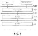
- FIG. 1 illustrates an overview of HPAV (HomePlug Audio Video) system 100, according to one embodiment of the present application.
- HPAV system 100 includes PHY (Physical) layer 110, MAC (Media Access Control) layer 120 and convergence layer 130.
- PHY layer 110 performs error-control correction, mapping into OFDM (Orthogonal Frequency Division Multiplexing) symbols, and generation of time-domain waveforms
- MAC layer 120 determines the correct position of transmission, formats data frames into fixed-length entities for transmission on the channel and ensures timely and error-free delivery through Automatic Repeat Request (ARQ);
- convergence layer 130 performs bridging, classification of traffic into connections, and data delivery smoothing functions.
- PHY layer 110, MAC layer 120 and convergence layer 130 perform the corresponding functions in the reverse.
- HPAV system 100 utilizes OFDM modulation technique due to its inherent adaptability in the presence of frequency selective channels, its resilience to narrow band interference, and its robustness to impulsive noise. Through the use of time-domain pulse shaping of the OFDM symbols, deep frequency notches can be achieved without the additional requirement of transmit notch filters. HPAV system 100 employs 1155 carriers, in the range from 1.80 MHz to 30.00 MHz.
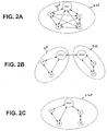
- FIG. 2A illustrates an exemplary Audio Video Logical Network (AVLN) for HPAV system 100 in FIG. 1 .
- An AVLN comprises a set of stations or devices that have the same Network Membership Key (NMK).
- NMK Network Membership Key
- an AVLN which is also generally referred to as a "powerline network” in the present application, one of the stations or devices becomes the Central Coordinator (CCo) device, which is responsible for coordinating the transmissions of all of the stations in the network, in order to achieve maximum overall network throughput as well as good QoS for each connection.
- the CCo is also responsible for authenticating stations that wish to join the network, managing encryption keys, and coordinating sharing of resources with neighbor networks.
- a CCo can either be preconfigured as such or be automatically selected through a specified selection procedure; however, only one station in an AVLN can function as a Central Coordinator (CCo) at one time. It is noted that the stations in an AVLN (i.e. a powerline network) can communicate via a powerline (i.e. an AC line).
- a powerline i.e. an AC line
- AVLN 202 includes stations A, B, C, and D and CCo1.
- the Physical Network (PhyNet) of a given station is the set of stations that can physically communicate with the station - at least at the level of Frame Control (FC) and ROBO (robust) mode.
- a PhyNet is relative to a given station, and it is possible for PhyNets of physically close-by stations to be distinct.
- a double arrow line such as double arrow line 204 in FIG. 2A , indicates an ability for two stations, such as station A and CCo1, to communicate on the PHY level. Also shown in FIG.
- FIG. 2B illustrates two exemplary AVLNs for HPAV system 100 in Figure 1 .
- AVLN 210 includes stations A and B and CCo1 and AVLN 212 includes CCo2 and stations C and D.
- the PhyNet for each station in FIG. 2B is shown in Table 1.
- FIG. 2C illustrates an exemplary AVLN for HPAV system 100 in Figure 1 .
- AVLN 220 includes CCo1 and stations A, B, C, and D.
- the PhyNet for each station in FIG. 2C is shown in Table 1.
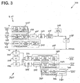
- FIG. 3 shows a diagram of an exemplary HPAV transceiver for HPAV system 100 in FIG. 1 .
- HPAV transceiver 300 includes transmitter side 310, which uses OFDM modulation, and receiver side 360.
- the PHY layer e.g. PHY layer 110 in Figure 1
- receives its inputs from the MAC layer e.g. MAC layer 120.
- Three separate processing chains are shown in FIG. 3 for different encoding for HomePlug 1.0.1 Frame Control (FC) data 312, HomePlug AV Frame Control data 314 and HomePlug AV Payload data 316, which are processed by 1.0.1 FC encoder 320, AV FC encoder 330 and AV payload data encoder 340, respectively.
- FC Frame Control
- the outputs of the three encoders lead into a common OFDM modulation structure, including mapper 350, Inverse Fast Fourier Transform (IFFT) processor 352, cyclic prefix insertion, symbol window and overlap block 352, and preamble insertion 356, which eventually feeds Analog Front End (AFE) module 358 that couples the signal to power line medium 390.
- mapper 350 Inverse Fast Fourier Transform (IFFT) processor 352, cyclic prefix insertion, symbol window and overlap block 352, and preamble insertion 356, which eventually feeds Analog Front End (AFE) module 358 that couples the signal to power line medium 390.
- IFFT Inverse Fast Fourier Transform
- AFE Analog Front End
- AFE 365 operates with an Automatic Gain Controller (AGC) 368 and a time-synchronization module 370 to feed separate frame control and payload data recovery circuits.
- the frame control data is recovered by processing the received sample stream through 384-point FFT 372 for HomePlug 1.0.1 delimiters, and 3072-point FFT 374 for HomePlug AV, and through separate frame control decoders 380 and 382 for respective.
- HomePlug 1.0.1 and HomePlug AV modes are examples of the received sample stream through 384-point FFT 372 for HomePlug 1.0.1 delimiters, and 3072-point FFT 374 for HomePlug AV, and through separate frame control decoders 380 and 382 for respective.
- the payload portion of the sampled time domain waveform which contains only HomePlug AV formatted symbols, is processed through 3072-point FFT 374, demodulator 375, and through de-interleaver 385, turbo convolutional decoder 386, and de-scrambler 387 of AV payload data decoder 384 to recover the AV payload data.
- the CCo of a network transmits a special signal called the beacon, which contains system-wide information, such as the network ID, the number of neighboring networks with which it coordinates, the current schedule of transmissions (e.g. which station is allowed to transmit and when), and the mode of the network (e.g. if it is in HPAV or in HPAV Hybrid mode).
- the beacon can also contain responses to messages from specific stations that request resources, request to join the network, or are delivered an encryption key, etc.
- the beacon is sent by the CCo at regular intervals that are tied to a specific phase of the power cycle, as discussed below in relation to FIG. 4 .
- the beacon is transmitted in a so-called ROBO (Robust) mode, which is used for reliable reception of the beacon by other stations, where each station experiences a different channel characteristic from the CCo to the station.
- ROBO Robot
- modulation is independent of the characteristics of the channel, and robustness is achieved through low rate coding, low density modulation, and repetition and interleaving of the payload.
- Each HPAV station monitors the channel for the presence of HP1.0 devices.
- a station detects the presence of HP1.0 devices, it notifies the CCo (e.g. CC01 in FIG. 2A ), which in turn switches the network (e.g. AVLN 202 in FIG. 2A ) to the HPAV Hybrid mode.
- CCo e.g. CC01 in FIG. 2A
- the network e.g. AVLN 202 in FIG. 2A
- HPAV networks avoid interference from HP1.0 stations by coaxing the HP1.0 stations to transmit only in the CSMA/CA region of the beacon period.
- HPAV stations and HP1.0 stations can coexist on the same medium, while HPAV stations maintain all the advantages of scheduled transmissions in the contention-free portion of the period.
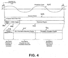
- FIG. 4 illustrates an exemplary beacon period synchronized to an exemplary powerline cycle, according to one example of the present invention.
- beacon period 402 i.e. the time between two consecutive beacon transmissions
- the beacon period is substantially equal to two periods of powerline cycle 404.
- the beacon period is nominally equal to 33.33 milliseconds (ms).
- beacon Period 402 is nominally equal to 40 ms.
- beacon period 402 can be precisely equal to two periods of powerline cycle 404.
- the start of beacon period 402 can be offset from the start of a powerline cycle by a fixed duration.
- beacon period 402 includes beacon region 406, CSMA (Carrier Sense Multiple Access) region 408, and reserved region 410.
- Beacon region 406 includes the beacon, which is generated by a CCo and can include a Preamble, a Frame Control, and a beacon payload.
- the CCo ensures that the beacon remains synchronized to the powerline cycle, independent of the CCo local clock frequency.
- Beacon region 406 also includes information regarding the duration of CSMA region 408 and reserved region 410.
- CSMA region 408 includes persistent shared CSMA allocation region 416, which is allocated to connections (i.e. sessions between transmitting and receiving stations) that use CSMA channel-access mechanism.
- Reserved region 410 which is the section of beacon period 402 during which only one station has permission to transmit, is further divided into persistent allocation region 412 and non-persistent allocation region 414.
- Persistent allocation region 412 is allocated to connections (i.e. sessions between transmitting and receiving stations), where the connections require QoS (Quality of Service).
- Non-persistent allocation region 414 is allocated to one or more of the following:
- the allocations in persistent allocation region 412 and the allocations in persistent shared CSMA allocation region 416 are controlled by a "Persistent Schedule,” and the allocations in non-persistent allocation region 414 are controlled by a "Non-persistent Schedule.” Both the Persistent Schedule and the Non-persistent Schedule are included in Broadcast messages in the beacon.
- the Persistent Schedule is valid for the current beacon period as well as for a number of subsequent beacon periods, where the number of subsequent beacon periods is indicated in the beacon. Since the Persistent Schedule remains valid for a number of subsequent beacon periods, it (i.e. the Persistent Schedule) allows all of the stations (e.g. stations A, B, C, and D in FIG. 2A ) in the network (e.g. AVLN 202 in Figure 2A ) to know the schedule, even if they occasionally fail to receive the beacon.
- stations e.g. stations A, B, C, and D in FIG. 2A
- the network e.g. AV
- the system e.g. HPAV system 100 in Figure 1
- the system can support a Preview Schedule, which provides a preview of the next schedule.
- a Preview Schedule provides a preview of the next schedule.
- the beacon can utilize a counter to indicate how many beacon periods will pass before the new schedule takes effect, for example.
- the Preview Schedule also allows some stations to miss beacon reception without losing schedule information.
- the Non-persistent Schedule is valid only for the beacon period in which it is announced. Consequently, if a station does not receive the beacon in a certain period, the station simply does not use any portion of non-persistent allocation region 414 during that period. On the other hand, when a station does receive the current beacon, it (i.e. the station) can take advantage of any allocation in non-persistent allocation region 414, either for its own use, or for the benefit of the system as a whole (e.g. in the form of the discover beacon).
- the Persistent and Non-persistent Schedules advantageously allow a more reliable distribution of the schedule in an unreliable medium, while at the same time allowing a swift reaction to rapidly changing conditions, or implementation of system functions without specific allocation of resources to such functions.
- the present invention provides an HPAV system including stations that communicate via a powerline in a powerline network, where one of the stations, which is designated as a CCo (Central Coordinator), generates a beacon that is synchronized to the powerline and includes Persistent and Non-persistent Schedules.
- CCo Central Coordinator
- the present invention achieves an HPAV system that advantageously provides flexible scheduling of resources in a powerline network environment.
Description
- The present invention relates generally to communication over an Ethernet-Class network and, more specifically to communication over a power line network.
- The vision of the networked home has driven many a business plan, but product offerings to date have been too limited in capability or in market potential to achieve the dream. Home networking is different than networking in the workplace. The applications are different, the traffic patterns are different, and the media available to carry the data are different. Certainly home networking users will want to transfer files between their computers and share peripherals such as printers. They will want gateways to broadband access so they can share their Internet connection between multiple devices. Users will also want other services, such as voice-over-IP (VoIP), streaming media for entertainment, and support for multi-player networked games.
- While some newer houses are wired with cables suitable for Ethernet, most are not. Thus, if choices for home network physical media are limited to phone wiring, wireless, and power line, there are a mixed bag of attributes.
- There has been a proliferation of wireless networking and related components in recent years. However, wireless communication suffers from limited range and less than universal coverage, i.e. certain areas of the home cannot communicate with others. These issues are particularly prominent in certain types of construction that result in poor signal propagation, such as those using steel frame and brick walls. Solutions to these issues are expensive and complex, and require some technical acumen not available to the average homeowner.
- Although telephone line networking may at first appear to be a solution, many households lack phone jacks at convenient locations to achieve the foreseeable benefits of home networking. For instance, some older houses may only have one phone jack located in the kitchen for use in the kitchen and other living areas (e.g. living room, family room, etc). Thus, it may be inconvenient or messy to provide network connections to remote devices. This picture is particularly unfavorable in less developed countries. Power plugs, on the other hand, are located in almost every room in the home, and some homes have multiple power outlets located on every wall of every room. The power line appears to be the most difficult medium of these three for communication, but it does have two appealing attributes. First, as with phone lines, no RF conversion hardware is needed and, thus, the cost can be low compared to wireless solutions. But more importantly, power outlets are almost everywhere someone might want to use a networked device at home.
- The power line medium is a harsh environment for communication. For instance, the channel between any two outlets in a home has the transfer function of an extremely complicated transmission line network with many unterminated stubs and some having terminating loads of varying impedance. Such a network has an amplitude and phase response that varies widely with frequency. At some frequencies the transmitted signal may arrive at the receiver with relatively little loss, while at other frequencies it may be driven below the noise floor. Worse, the transfer function can change with time. This might happen because the homeowner has plugged a new device into the power line, or if some of the devices plugged into the network have time-varying impedance. As a result, the transfer function of the channel between outlet pairs may vary over a wide range. In some cases, a broad swath of bandwidth may be suitable for high quality transmission, while in other cases the channel may have a limited capacity to carry data.
- With many power outlets available for plugging in a new networked device at any time, the issues involving the management and coordination of the networked devices bring about concerns regarding the overall throughput of the network, Quality of Service (QoS) for each connection, authentication, coordination, and sharing of the network resources. Accordingly, there is a need in the art for management and coordination schemes that can effectively and efficiently address such concerns.
EP-A-1 179 919 discloses an access contention scheme having both multi-level priorities and a contention-free access indicator for use by a station in a network of stations. -
US-A-7 623 542 discloses a method of operating in a network in which stations communicate over a shared medium. The method provides regularly repeated contention free intervals, CSMA communication during times outside the contention free intervals, and distributed control over the initiation and makeup of the contention free intervals to a plurality of stations so that any of the plurality of stations can independently initiate transmission within the contention free interval. -
US-A-6 587 474 describes a data bus which is shared by several components. The components possess a hierarchical transmission token and are synchronized by a synchronization pulse. A clock signal of the synchronization pulse has a rate which is between the duration of transmission of the component with the highest priority token and the cumulative duration of transmission of all components. - The present invention is defined in the attached independent claim. Further, preferred features may be found in the dependent claims appended hereto.
- Other features and advantages of the present invention will become more readily apparent to those of ordinary skill in the art after reviewing the following detailed description and accompanying drawings.
- The features and advantages of the present invention will become more readily apparent to those ordinarily skilled in the art after reviewing the following detailed description and accompanying drawings, wherein:
-
FIG. 1 illustrates an overview of a HPAV (HomePlug Audio Video) system, -
FIG. 2A illustrates a diagram of an exemplary powerline network configuration for the HPAV system inFIG. 1 . -
FIG. 2B illustrates a diagram of another exemplary powerline network configuration for the HPAV system inFIG. 1 . -
FIG. 2C illustrates a diagram of another exemplary powerline network configuration for the HPAV system inFIG. 1 . -
FIG 3 illustrates a diagram of an exemplary HPAV transceiver for HPAV system 100 inFIG. 1 . -
FIG 4 illustrates a diagram of an exemplary beacon period. - Moreover, in the description of the present invention, certain details have been left out in order to not obscure the inventive aspects of the invention. The details left out are within the knowledge of a person of ordinary skill in the art.
- The drawings in the present application and their accompanying detailed description are directed to merely example embodiments of the invention. To maintain brevity, other embodiments of the invention which use the principles of the present invention are not specifically described in the present application and are not specifically illustrated by the present drawings. It should be borne in mind that, unless noted otherwise, like or corresponding elements among the figures may be indicated by like or corresponding reference numerals.
-
FIG. 1 illustrates an overview of HPAV (HomePlug Audio Video) system 100, according to one embodiment of the present application. As shown, HPAV system 100 includes PHY (Physical) layer 110, MAC (Media Access Control)layer 120 andconvergence layer 130. When HPAV system 100 is in transmit mode, PHY layer 110 performs error-control correction, mapping into OFDM (Orthogonal Frequency Division Multiplexing) symbols, and generation of time-domain waveforms;MAC layer 120 determines the correct position of transmission, formats data frames into fixed-length entities for transmission on the channel and ensures timely and error-free delivery through Automatic Repeat Request (ARQ); andconvergence layer 130 performs bridging, classification of traffic into connections, and data delivery smoothing functions. Conversely, when HPAV system 100 is in receive mode, PHY layer 110,MAC layer 120 andconvergence layer 130 perform the corresponding functions in the reverse. { XE " System block diagram" } - HPAV system 100 utilizes OFDM modulation technique due to its inherent adaptability in the presence of frequency selective channels, its resilience to narrow band interference, and its robustness to impulsive noise. Through the use of time-domain pulse shaping of the OFDM symbols, deep frequency notches can be achieved without the additional requirement of transmit notch filters. HPAV system 100 employs 1155 carriers, in the range from 1.80 MHz to 30.00 MHz.
-
FIG. 2A illustrates an exemplary Audio Video Logical Network (AVLN) for HPAV system 100 inFIG. 1 . An AVLN comprises a set of stations or devices that have the same Network Membership Key (NMK). In an AVLN, which is also generally referred to as a "powerline network" in the present application, one of the stations or devices becomes the Central Coordinator (CCo) device, which is responsible for coordinating the transmissions of all of the stations in the network, in order to achieve maximum overall network throughput as well as good QoS for each connection. The CCo is also responsible for authenticating stations that wish to join the network, managing encryption keys, and coordinating sharing of resources with neighbor networks. A CCo can either be preconfigured as such or be automatically selected through a specified selection procedure; however, only one station in an AVLN can function as a Central Coordinator (CCo) at one time. It is noted that the stations in an AVLN (i.e. a powerline network) can communicate via a powerline (i.e. an AC line). - As shown in
FIG. 2A ,AVLN 202 includes stations A, B, C, and D and CCo1. The Physical Network (PhyNet) of a given station is the set of stations that can physically communicate with the station - at least at the level of Frame Control (FC) and ROBO (robust) mode. A PhyNet is relative to a given station, and it is possible for PhyNets of physically close-by stations to be distinct. In the present application, it is noted that a double arrow line, such asdouble arrow line 204 inFIG. 2A , indicates an ability for two stations, such as station A and CCo1, to communicate on the PHY level. Also shown inFIG. 2A , all stations can communicate with each other and, consequently, the PhyNet of all stations is the same set {A, B, C; D, CCo1}, as shown in Table 1. Two stations belonging to an AVLN can communicate with each other if they belong to each other's PhyNet. Further shown inFIG. 2A ,AVLN 202 coincides with the PhyNet of each station inAVLN 202.Table 1 Physical Networks (PhyNets) in ... Station Figure 2A Figure 2B Figure 2C A {A,B,C,D,CCo1} {A,B,CCo1} {A,B,CCo1} B {A,B,C,D,CCo1} {A,B,CCo1} {A,B,CCo1} C {A,B,C,D,CCo1} {C.D,CCo2} {C,D,CCo1} D {A,B,C,D,CCo1} {C,D,CCo2} {C,D} CCo1 {A,B,C,D,CCo1} {A,B,CCo1,CCo2} {A,B,C,CCo1} CCo2 N/A {C,D,CCo1,CCo2} N/A -
FIG. 2B illustrates two exemplary AVLNs for HPAV system 100 inFigure 1 . As shown inFIG. 2B ,AVLN 210 includes stations A and B and CCo1 andAVLN 212 includes CCo2 and stations C and D. The PhyNet for each station inFIG. 2B is shown in Table 1. -
FIG. 2C illustrates an exemplary AVLN for HPAV system 100 inFigure 1 . As shown inFIG. 2C ,AVLN 220 includes CCo1 and stations A, B, C, and D. The PhyNet for each station inFIG. 2C is shown in Table 1. -
FIG. 3 shows a diagram of an exemplary HPAV transceiver for HPAV system 100 inFIG. 1 .HPAV transceiver 300 includestransmitter side 310, which uses OFDM modulation, andreceiver side 360. Ontransmitter side 310, the PHY layer (e.g. PHY layer 110 inFigure 1 ) receives its inputs from the MAC layer (e.g. MAC layer 120). Three separate processing chains are shown inFIG. 3 for different encoding for HomePlug 1.0.1 Frame Control (FC) data 312, HomePlug AV Frame Control data 314 and HomePlugAV Payload data 316, which are processed by 1.0.1FC encoder 320,AV FC encoder 330 and AVpayload data encoder 340, respectively. The outputs of the three encoders lead into a common OFDM modulation structure, includingmapper 350, Inverse Fast Fourier Transform (IFFT)processor 352, cyclic prefix insertion, symbol window and overlap block 352, andpreamble insertion 356, which eventually feeds Analog Front End (AFE)module 358 that couples the signal topower line medium 390. - At
receiver side 360,AFE 365 operates with an Automatic Gain Controller (AGC) 368 and a time-synchronization module 370 to feed separate frame control and payload data recovery circuits. The frame control data is recovered by processing the received sample stream through 384-point FFT 372 for HomePlug 1.0.1 delimiters, and 3072-point FFT 374 for HomePlug AV, and through separateframe control decoders point FFT 374,demodulator 375, and throughde-interleaver 385,turbo convolutional decoder 386, andde-scrambler 387 of AVpayload data decoder 384 to recover the AV payload data. - In the present invention, the CCo of a network (e.g. CCo1 of
AVLN 202 inFIG. 2A ) transmits a special signal called the beacon, which contains system-wide information, such as the network ID, the number of neighboring networks with which it coordinates, the current schedule of transmissions (e.g. which station is allowed to transmit and when), and the mode of the network (e.g. if it is in HPAV or in HPAV Hybrid mode). The beacon can also contain responses to messages from specific stations that request resources, request to join the network, or are delivered an encryption key, etc. The beacon is sent by the CCo at regular intervals that are tied to a specific phase of the power cycle, as discussed below in relation toFIG. 4 . The beacon is transmitted in a so-called ROBO (Robust) mode, which is used for reliable reception of the beacon by other stations, where each station experiences a different channel characteristic from the CCo to the station. In the ROBO mode, modulation is independent of the characteristics of the channel, and robustness is achieved through low rate coding, low density modulation, and repetition and interleaving of the payload. - Each HPAV station (e.g. stations A, B, C, and D in
FIG. 2A ) monitors the channel for the presence of HP1.0 devices. When a station detects the presence of HP1.0 devices, it notifies the CCo (e.g. CC01 inFIG. 2A ), which in turn switches the network (e.g.AVLN 202 inFIG. 2A ) to the HPAV Hybrid mode. In the Hybrid mode operation, HPAV networks avoid interference from HP1.0 stations by coaxing the HP1.0 stations to transmit only in the CSMA/CA region of the beacon period. Thus HPAV stations and HP1.0 stations can coexist on the same medium, while HPAV stations maintain all the advantages of scheduled transmissions in the contention-free portion of the period. -
FIG. 4 illustrates an exemplary beacon period synchronized to an exemplary powerline cycle, according to one example of the present invention. As shown inFIG. 4 , beacon period 402 (i.e. the time between two consecutive beacon transmissions) is substantially equal to two periods ofpowerline cycle 404. For example, for a powerline frequency of 60 Hz (i.e. for a 60 Hz system), the beacon period is nominally equal to 33.33 milliseconds (ms). For example, for a powerline frequency of 50 Hz (i.e. for a 50 Hz system),beacon Period 402 is nominally equal to 40 ms. In one example,beacon period 402 can be precisely equal to two periods ofpowerline cycle 404. As further shown inFIG. 4 , the start ofbeacon period 402 can be offset from the start of a powerline cycle by a fixed duration. - As also shown in
FIG. 4 ,beacon period 402 includesbeacon region 406, CSMA (Carrier Sense Multiple Access)region 408, and reservedregion 410.Beacon region 406 includes the beacon, which is generated by a CCo and can include a Preamble, a Frame Control, and a beacon payload. The CCo ensures that the beacon remains synchronized to the powerline cycle, independent of the CCo local clock frequency. - Information describing allocations within
beacon period 402 is broadcast in the beacon payload by using one or more beacon entries.Beacon region 406 also includes information regarding the duration ofCSMA region 408 and reservedregion 410.CSMA region 408 includes persistent sharedCSMA allocation region 416, which is allocated to connections (i.e. sessions between transmitting and receiving stations) that use CSMA channel-access mechanism.Reserved region 410, which is the section ofbeacon period 402 during which only one station has permission to transmit, is further divided intopersistent allocation region 412 andnon-persistent allocation region 414.Persistent allocation region 412 is allocated to connections (i.e. sessions between transmitting and receiving stations), where the connections require QoS (Quality of Service).Non-persistent allocation region 414 is allocated to one or more of the following: - (a) active connections that have allocation in
persistent allocation region 412 but may need extra capacity, either because the channel has deteriorated for a brief or longer period of time, or because the requirements of a particular application have increased (e.g. during video or audio fast forward); - (b) an additional CSMA period (e.g. when the CCo senses high level of collisions in the regular CSMA period; and
- (c) special system needs, such as a discover beacon, whose purpose is to discover hidden nodes (i.e. stations) that cannot detect or hear the CCo.
- The allocations in
persistent allocation region 412 and the allocations in persistent sharedCSMA allocation region 416 are controlled by a "Persistent Schedule," and the allocations innon-persistent allocation region 414 are controlled by a "Non-persistent Schedule." Both the Persistent Schedule and the Non-persistent Schedule are included in Broadcast messages in the beacon. The Persistent Schedule is valid for the current beacon period as well as for a number of subsequent beacon periods, where the number of subsequent beacon periods is indicated in the beacon. Since the Persistent Schedule remains valid for a number of subsequent beacon periods, it (i.e. the Persistent Schedule) allows all of the stations (e.g. stations A, B, C, and D inFIG. 2A ) in the network (e.g.AVLN 202 inFigure 2A ) to know the schedule, even if they occasionally fail to receive the beacon. - In addition to the Persistent Schedule, the system (e.g. HPAV system 100 in
Figure 1 ) can support a Preview Schedule, which provides a preview of the next schedule. Thus, when a schedule change is necessary, the new schedule can be announced before it actually takes effect. The beacon can utilize a counter to indicate how many beacon periods will pass before the new schedule takes effect, for example. The Preview Schedule also allows some stations to miss beacon reception without losing schedule information. - In contrast to the Persistent Schedule, the Non-persistent Schedule is valid only for the beacon period in which it is announced. Consequently, if a station does not receive the beacon in a certain period, the station simply does not use any portion of
non-persistent allocation region 414 during that period. On the other hand, when a station does receive the current beacon, it (i.e. the station) can take advantage of any allocation innon-persistent allocation region 414, either for its own use, or for the benefit of the system as a whole (e.g. in the form of the discover beacon). - The Persistent and Non-persistent Schedules advantageously allow a more reliable distribution of the schedule in an unreliable medium, while at the same time allowing a swift reaction to rapidly changing conditions, or implementation of system functions without specific allocation of resources to such functions.
- Thus, as discussed above, the present invention provides an HPAV system including stations that communicate via a powerline in a powerline network, where one of the stations, which is designated as a CCo (Central Coordinator), generates a beacon that is synchronized to the powerline and includes Persistent and Non-persistent Schedules. As a result, the present invention achieves an HPAV system that advantageously provides flexible scheduling of resources in a powerline network environment.
- From the above description of the invention it is manifest that various techniques can be used for implementing the concepts of the present invention without departing from its scope. Moreover, while the invention has been described with specific reference to certain embodiments, a person of ordinary skill in the art would recognize that changes could be made in form and detail without departing from the scope of the invention. For example, it is contemplated that the circuitry disclosed herein can be implemented in software and/or hardware, and the software may be stored in any storage medium or memory. The described embodiments are to be considered in all respects as illustrative and not restrictive. It should also be understood that the invention is not limited to the particular embodiments described herein, but is capable of many rearrangements, modifications, and substitutions without departing from the scope of the invention.
Claims (7)
- A method for coordinating transmissions on a centrally coordinated powerline network (202, 210, 212, 220), said method comprising:transmitting beacons by a central coordinator (CCo1, CCo2) to a plurality of stations (A, B, C, D) to define beacon periods (402) beginning at pre-defined phases of a powerline cycle (404), wherein said beacons contain at least transmission schedules for at least said beacon periods (402);wherein said transmission schedules contain allocations fixed in phase relative to the powerline cycle (404);and characterized in that said beacon transmissions include a persistent schedule (412, 416) valid for a current beacon period (402) and a number of subsequent beacon periods (402) defining the schedule of transmissions which said plurality of stations (A, B, C, D) follow, at least when one or more beacons of said subsequent beacon periods (402) are not received by at least one of said plurality of stations (A, B, C, D).
- The method of claim 1, wherein said beacon includes a network identification, a network mode, a number of neighbor networks and a current schedule.
- The method of claim 1, wherein said beacon (402) is equal to two periods of said cycle (404) of said powerline.
- A device (CCo1) for coordinating transmissions by a plurality of network devices (A, B, C, D) in a centrally coordinated powerline network (202, 210, 212, 220), said device comprising:a configuring unit to configure said device to be a central coordinator capable of generating beacons, wherein said beacons define beacon periods (402) beginning at pre-defined phases of a powerline cycle (404) and contain at least transmission schedules for at least said beacon periods (402); anda beacon transmitter (310) to transmit said beacons to said plurality of network devices (A, B, C, D);wherein said transmission schedules contain allocations fixed in phase relative to the powerline cycle (404);and characterized in that said beacon transmissions include a persistent schedule (412, 416) valid for a current beacon period (402) and a number of subsequent beacon periods (402) defining the schedule of transmissions which said plurality of stations (A, B, C, D) follow, at least when one or more beacons of said subsequent beacon periods (402) are not received by at least one of said plurality of stations (A, B, C, D).
- The device (CCo1) of claim 4, wherein said beacon includes a network identification, a network mode, a number of neighbor networks and a current schedule.
- The method of claim 1 and wherein said transmitting comprises transmitting said beacons at said pre-defined phases.
- The device (CCo1) of claim 4 and wherein said transmitter (310) transmits said beacons at said pre-defined phases.
Applications Claiming Priority (2)
| Application Number | Priority Date | Filing Date | Title |
|---|---|---|---|
| US70271705P | 2005-07-27 | 2005-07-27 | |
| PCT/US2006/028662 WO2007016031A2 (en) | 2005-07-27 | 2006-07-24 | Flexible scheduling of resources in a noisy environment |
Publications (3)
| Publication Number | Publication Date |
|---|---|
| EP1908222A2 EP1908222A2 (en) | 2008-04-09 |
| EP1908222A4 EP1908222A4 (en) | 2009-10-28 |
| EP1908222B1 true EP1908222B1 (en) | 2016-02-03 |
Family
ID=37709095
Family Applications (3)
| Application Number | Title | Priority Date | Filing Date |
|---|---|---|---|
| EP06788309.0A Active EP1908189B1 (en) | 2005-07-27 | 2006-07-24 | Bandwidth management in a powerline network |
| EP06788301.7A Active EP1908223B1 (en) | 2005-07-27 | 2006-07-24 | Communicating schedule and network information in a powerline network |
| EP06788300.9A Active EP1908222B1 (en) | 2005-07-27 | 2006-07-24 | Flexible scheduling of resources in a noisy environment |
Family Applications Before (2)
| Application Number | Title | Priority Date | Filing Date |
|---|---|---|---|
| EP06788309.0A Active EP1908189B1 (en) | 2005-07-27 | 2006-07-24 | Bandwidth management in a powerline network |
| EP06788301.7A Active EP1908223B1 (en) | 2005-07-27 | 2006-07-24 | Communicating schedule and network information in a powerline network |
Country Status (5)
| Country | Link |
|---|---|
| EP (3) | EP1908189B1 (en) |
| JP (3) | JP2009504015A (en) |
| KR (3) | KR101247294B1 (en) |
| CN (7) | CN101273550A (en) |
| WO (3) | WO2007016032A2 (en) |
Families Citing this family (30)
| Publication number | Priority date | Publication date | Assignee | Title |
|---|---|---|---|---|
| GB2452697A (en) | 2007-08-14 | 2009-03-18 | Nec Corp | Dynamically allocating new resources to a node provided with persistently allocated resources |
| US20100284364A1 (en) * | 2007-12-29 | 2010-11-11 | Mingli You | Semi-persistent scheduling method and apparatus based on statistically multiplexing in time and frequency resources |
| EP2320285A1 (en) * | 2009-11-06 | 2011-05-11 | VEGA Grieshaber KG | Data processing device for a field device |
| EP2323443A1 (en) * | 2009-11-16 | 2011-05-18 | NEC Corporation | Method for transmitting beacon services in an area covered by several radio access technologies |
| JP5815553B2 (en) * | 2010-03-24 | 2015-11-17 | レノボ・イノベーションズ・リミテッド(香港) | Stamping mechanism for transmitting beacon messages |
| US8938237B2 (en) | 2010-03-24 | 2015-01-20 | Nec Corporation | Stamping mechanism for beacon message transmission |
| US8660013B2 (en) | 2010-04-12 | 2014-02-25 | Qualcomm Incorporated | Detecting delimiters for low-overhead communication in a network |
| US8743908B2 (en) * | 2010-04-20 | 2014-06-03 | Texas Instruments Incorporated | Coexistence of prime, S-FSK and G3 devices in powerline communications |
| CN102244558B (en) * | 2010-05-12 | 2014-09-03 | 华为技术有限公司 | Data transmission method and device |
| CN102215049B (en) * | 2011-05-27 | 2014-01-29 | 杭州箭源电子有限公司 | Data sending method and data sending device |
| US9744442B2 (en) | 2012-08-27 | 2017-08-29 | Lenovo Enterprise Solutions (Singapore) Pte. Ltd. | Dynamic quality of service management in multiplayer gaming |
| AT513542B1 (en) * | 2012-11-15 | 2014-07-15 | Fronius Int Gmbh | Method and arrangement for data communication between an inverter and a grid monitoring unit |
| KR101420227B1 (en) * | 2012-11-21 | 2014-07-17 | 한국전기연구원 | Fast Power Line Communication Method using Efficient Resource Allocation Scheme for Coexistence of Heterogeneous Systems |
| US9071390B2 (en) * | 2013-01-10 | 2015-06-30 | Qualcomm Incorporated | Adjusting physical layer transmission properties |
| US9237014B2 (en) * | 2013-05-28 | 2016-01-12 | Hong Kong Applied Science & Technology Research Institute Company, Limited | Partial CipherText updates using variable-length segments delineated by pattern matching and encrypted by fixed-length blocks |
| US9537641B2 (en) * | 2013-05-30 | 2017-01-03 | Qualcomm Incorporated | Channel adaptation to compensate for interference from neighbor powerline communication networks |
| US9549027B2 (en) | 2013-09-27 | 2017-01-17 | Dolby Laboratories Licensing Corporation | Network-synchronized media playback |
| US9723610B2 (en) * | 2015-04-07 | 2017-08-01 | Qualcomm Incorporated | Multi-layer timing synchronization framework |
| CN107395318B (en) * | 2016-05-17 | 2020-08-14 | 联发科技股份有限公司 | Apparatus and method for selecting a frequency map |
| WO2018090339A1 (en) * | 2016-11-18 | 2018-05-24 | 海能达通信股份有限公司 | Wireless communication method and device, and communication apparatus |
| CN107505839B (en) * | 2017-07-21 | 2019-06-28 | 中国地质大学(武汉) | A kind of synchronous waveform method and system of virtual instrument |
| CN110768776A (en) * | 2018-07-25 | 2020-02-07 | 杭州万高科技股份有限公司 | Smart power grid timing synchronization method, system, equipment and computer medium |
| CN109039381B (en) * | 2018-08-29 | 2022-08-05 | 珠海泰易科技有限公司 | Encryption method for low-voltage power line broadband carrier communication aiming at DL/T645 communication protocol |
| CN113785538B (en) * | 2019-05-03 | 2024-04-02 | 微芯片技术股份有限公司 | Media access for time-sensitive and best effort data packets and related systems, methods and devices |
| CN111245477B (en) * | 2020-01-16 | 2022-02-22 | 磐基技术有限公司 | Power failure detection method of communication equipment |
| CN113595592A (en) | 2020-04-30 | 2021-11-02 | 华为技术有限公司 | Time synchronization method, device and storage medium |
| CN111542015B (en) * | 2020-05-11 | 2022-03-15 | 国网陕西省电力公司电力科学研究院 | MAC protocol method applied to transformer substation wireless sensor network and implementation system thereof |
| CN113794530B (en) * | 2021-09-09 | 2023-12-01 | 深圳市力合微电子股份有限公司 | TDMA-based low-power consumption micropower wireless communication method |
| CN114124600B (en) * | 2021-11-15 | 2023-06-06 | 国网湖北省电力有限公司营销服务中心(计量中心) | Power line broadband carrier system supporting home subnetwork and application method thereof |
| US20230412266A1 (en) * | 2022-05-19 | 2023-12-21 | Nec Laboratories America, Inc. | Time synchronization method with trusted beacons and distributed fiber sensing |
Family Cites Families (41)
| Publication number | Priority date | Publication date | Assignee | Title |
|---|---|---|---|---|
| JPS63191423A (en) * | 1987-02-03 | 1988-08-08 | Fujitsu Ltd | Satellite communication system |
| US5553094A (en) * | 1990-02-15 | 1996-09-03 | Iris Systems, Inc. | Radio communication network for remote data generating stations |
| US6334219B1 (en) * | 1994-09-26 | 2001-12-25 | Adc Telecommunications Inc. | Channel selection for a hybrid fiber coax network |
| JPH08265241A (en) * | 1995-03-28 | 1996-10-11 | Hitachi Ltd | Satellite communication system and satellite communication method |
| US5659720A (en) * | 1995-04-27 | 1997-08-19 | Emulex Corporatioln | Computer control device for managing a timer array |
| WO1998009845A1 (en) * | 1996-09-07 | 1998-03-12 | Bayerische Motoren Werke Aktiengesellschaft | Data bus for several apparatuses |
| US6708274B2 (en) * | 1998-04-30 | 2004-03-16 | Intel Corporation | Cryptographically protected paging subsystem |
| US6567416B1 (en) * | 1997-10-14 | 2003-05-20 | Lucent Technologies Inc. | Method for access control in a multiple access system for communications networks |
| US6055316A (en) * | 1997-12-26 | 2000-04-25 | Sun Microsystems, Inc. | System and method for deriving an appropriate initialization vector for secure communications |
| JPH11261545A (en) * | 1998-03-10 | 1999-09-24 | Hitachi Denshi Ltd | Video and audio signal transmission system |
| CN1296682A (en) * | 1998-12-17 | 2001-05-23 | 三菱电机株式会社 | Transmitting method and device |
| US6278357B1 (en) * | 1999-02-04 | 2001-08-21 | Electric Power Research Institute, Inc. | Apparatus and method for implementing digital communications on a power line |
| FI115494B (en) * | 1999-09-08 | 2005-05-13 | Nokia Corp | Base station frequency synchronization |
| US7254116B2 (en) * | 2000-04-07 | 2007-08-07 | Broadcom Corporation | Method and apparatus for transceiver noise reduction in a frame-based communications network |
| US7352770B1 (en) * | 2000-08-04 | 2008-04-01 | Intellon Corporation | Media access control protocol with priority and contention-free intervals |
| JP4373598B2 (en) * | 2000-10-26 | 2009-11-25 | 株式会社日立製作所 | Power line carrier system |
| US6834091B2 (en) * | 2001-04-03 | 2004-12-21 | Thomson Licensing S.A. | Time synchronization for data over a powerline modem network |
| US6577231B2 (en) * | 2001-04-03 | 2003-06-10 | Thomson Licensing Sa | Clock synchronization over a powerline modem network for multiple devices |
| ES2186531B1 (en) * | 2001-04-19 | 2005-03-16 | Diseño De Sistemas En Silicio, S.A. | PROCEDURE FOR MULTIPLE AND MULTIPLE DATA TRANSMISSION FOR A MULTI-USER DIGITAL DATA TRANSMISSION SYSTEM POINT TO MULTIPOINT ON ELECTRICAL NETWORK. |
| ATE445986T1 (en) * | 2001-05-14 | 2009-10-15 | Ericsson Ab | METHOD AND SYSTEM FOR RESERVING TIME SLOTS IN A TDMA SYSTEM |
| US7570656B2 (en) * | 2001-06-18 | 2009-08-04 | Yitran Communications Ltd. | Channel access method for powerline carrier based media access control protocol |
| US20040174851A1 (en) * | 2001-07-17 | 2004-09-09 | Yeshayahu Zalitzky | Dual purpose power line modem |
| JP4298651B2 (en) * | 2002-05-31 | 2009-07-22 | コーニンクレッカ フィリップス エレクトロニクス エヌ ヴィ | Message routing method, wireless network and master node |
| US6744766B2 (en) * | 2002-06-05 | 2004-06-01 | Meshnetworks, Inc. | Hybrid ARQ for a wireless Ad-Hoc network and a method for using the same |
| US7200178B2 (en) * | 2002-06-12 | 2007-04-03 | Texas Instruments Incorporated | Methods for optimizing time variant communication channels |
| US7307357B2 (en) * | 2002-09-30 | 2007-12-11 | Amperion, Inc. | Method and system to increase the throughput of a communications system that uses an electrical power distribution system as a communications pathway |
| AU2003284317A1 (en) * | 2002-10-21 | 2004-05-13 | Intellon Corporation | Contention-free access intervals on a csma network |
| US7277548B2 (en) * | 2002-10-23 | 2007-10-02 | Ndosa Technologies, Inc. | Cryptographic method and computer program product for use in wireless local area networks |
| US7719991B2 (en) * | 2003-01-21 | 2010-05-18 | Qualcomm Incorporated | Reverse rate indicator detection |
| US8064474B2 (en) | 2003-03-20 | 2011-11-22 | Qualcomm Atheros, Inc. | Method and apparatus for selecting a responder to enable reliable multicast |
| US6911276B2 (en) * | 2003-04-15 | 2005-06-28 | Entegris, Inc. | Fuel cell with ultraphobic surfaces |
| US7423992B2 (en) * | 2003-04-16 | 2008-09-09 | Sony Corporation | Time slot and carrier frequency allocation in a network |
| KR101025085B1 (en) * | 2003-08-06 | 2011-03-25 | 파나소닉 주식회사 | Master station of communication system and access control method |
| JP4488828B2 (en) * | 2003-08-06 | 2010-06-23 | パナソニック株式会社 | Master station of communication system and access control method |
| JP4011527B2 (en) * | 2003-08-29 | 2007-11-21 | シャープ株式会社 | COMMUNICATION RELAY DEVICE, COMMUNICATION DEVICE, COMMUNICATION SYSTEM, COMMUNICATION METHOD, COMMUNICATION PROGRAM, AND RECORDING MEDIUM CONTAINING THE SAME |
| US7092693B2 (en) * | 2003-08-29 | 2006-08-15 | Sony Corporation | Ultra-wide band wireless / power-line communication system for delivering audio/video content |
| WO2005048511A2 (en) * | 2003-11-07 | 2005-05-26 | Sharp Laboratories Of America, Inc. | Systems and methods for network channel allocation |
| JP3673268B1 (en) * | 2004-02-05 | 2005-07-20 | シャープ株式会社 | Jitter correction device |
| ATE405057T1 (en) * | 2004-06-15 | 2008-08-15 | Dublin Inst Of Technology | SYSTEME DE SONDE SANS FIL POUR RESEAUX LOCAUX SANS FIL |
| US8126065B2 (en) * | 2005-03-23 | 2012-02-28 | Sony Corporation | Automatic power adjustment in powerline home network |
| US20060227729A1 (en) * | 2005-04-12 | 2006-10-12 | Honeywell International Inc. | Wireless communication system with collision avoidance protocol |
-
2006
- 2006-07-24 WO PCT/US2006/028663 patent/WO2007016032A2/en active Search and Examination
- 2006-07-24 EP EP06788309.0A patent/EP1908189B1/en active Active
- 2006-07-24 JP JP2008524027A patent/JP2009504015A/en active Pending
- 2006-07-24 KR KR1020087004686A patent/KR101247294B1/en active IP Right Grant
- 2006-07-24 EP EP06788301.7A patent/EP1908223B1/en active Active
- 2006-07-24 WO PCT/US2006/028662 patent/WO2007016031A2/en active Application Filing
- 2006-07-24 WO PCT/US2006/028675 patent/WO2007016034A2/en active Application Filing
- 2006-07-24 CN CNA2006800355657A patent/CN101273550A/en active Pending
- 2006-07-24 EP EP06788300.9A patent/EP1908222B1/en active Active
- 2006-07-24 CN CN201310278303.5A patent/CN103532809B/en active Active
- 2006-07-24 JP JP2008524029A patent/JP2009504017A/en active Pending
- 2006-07-24 JP JP2008524028A patent/JP5106394B2/en active Active
- 2006-07-24 CN CN2006800355553A patent/CN101273580B/en active Active
- 2006-07-24 CN CN200680035606.2A patent/CN101326768B/en active Active
- 2006-07-24 KR KR1020087004685A patent/KR20080038366A/en not_active Application Discontinuation
- 2006-07-27 CN CN2006101075871A patent/CN101026411B/en active Active
- 2006-07-27 CN CN2006800352678A patent/CN101542961B/en not_active Expired - Fee Related
- 2006-07-27 CN CN2006800352803A patent/CN101317391B/en active Active
-
2008
- 2008-02-27 KR KR1020087004684A patent/KR101269036B1/en active IP Right Grant
Also Published As
Similar Documents
| Publication | Publication Date | Title |
|---|---|---|
| EP1908222B1 (en) | Flexible scheduling of resources in a noisy environment | |
| US8553706B2 (en) | Flexible scheduling of resources in a noisy environment | |
| US8737420B2 (en) | Bandwidth management in a powerline network | |
| US20070025266A1 (en) | Communicating schedule and network information in a powerline network | |
| EP1634463B1 (en) | Method and apparatus for non-centralized network bandwidth management | |
| EP2294721B1 (en) | Managing coexistence among signaling protocols on a shared medium | |
| JP5758360B2 (en) | Communication method and power line communication system | |
| US8520683B2 (en) | Managing communications over a shared medium | |
| US6011781A (en) | Multipoint access protocol utilizing a point-to-point methodology | |
| KR20100019504A (en) | Managing distributed access to a shared medium | |
| Galli et al. | Industrial and International Standards on PLC‐Based Networking Technologies | |
| Adams | Home area network technologies |
Legal Events
| Date | Code | Title | Description |
|---|---|---|---|
| PUAI | Public reference made under article 153(3) epc to a published international application that has entered the european phase |
Free format text: ORIGINAL CODE: 0009012 |
|
| 17P | Request for examination filed |
Effective date: 20080214 |
|
| AK | Designated contracting states |
Kind code of ref document: A2 Designated state(s): AT BE BG CH CY CZ DE DK EE ES FI FR GB GR HU IE IS IT LI LT LU LV MC NL PL PT RO SE SI SK TR |
|
| RAP1 | Party data changed (applicant data changed or rights of an application transferred) |
Owner name: COPPERGATE COMMUNICATIONS LTD. |
|
| RAP1 | Party data changed (applicant data changed or rights of an application transferred) |
Owner name: COPPERGATE COMMUNICATIONS LTD. |
|
| A4 | Supplementary search report drawn up and despatched |
Effective date: 20090925 |
|
| RIC1 | Information provided on ipc code assigned before grant |
Ipc: H04B 3/54 20060101ALI20090921BHEP Ipc: H04L 12/413 20060101AFI20080116BHEP |
|
| DAX | Request for extension of the european patent (deleted) | ||
| RAP1 | Party data changed (applicant data changed or rights of an application transferred) |
Owner name: SIGMA DESIGNS ISRAEL S.D.I LTD. |
|
| 17Q | First examination report despatched |
Effective date: 20140512 |
|
| 17Q | First examination report despatched |
Effective date: 20141219 |
|
| GRAP | Despatch of communication of intention to grant a patent |
Free format text: ORIGINAL CODE: EPIDOSNIGR1 |
|
| INTG | Intention to grant announced |
Effective date: 20150708 |
|
| GRAS | Grant fee paid |
Free format text: ORIGINAL CODE: EPIDOSNIGR3 |
|
| GRAA | (expected) grant |
Free format text: ORIGINAL CODE: 0009210 |
|
| AK | Designated contracting states |
Kind code of ref document: B1 Designated state(s): AT BE BG CH CY CZ DE DK EE ES FI FR GB GR HU IE IS IT LI LT LU LV MC NL PL PT RO SE SI SK TR |
|
| REG | Reference to a national code |
Ref country code: GB Ref legal event code: FG4D |
|
| REG | Reference to a national code |
Ref country code: AT Ref legal event code: REF Ref document number: 774112 Country of ref document: AT Kind code of ref document: T Effective date: 20160215 Ref country code: CH Ref legal event code: EP |
|
| REG | Reference to a national code |
Ref country code: IE Ref legal event code: FG4D |
|
| REG | Reference to a national code |
Ref country code: DE Ref legal event code: R096 Ref document number: 602006047897 Country of ref document: DE |
|
| REG | Reference to a national code |
Ref country code: NL Ref legal event code: FP |
|
| REG | Reference to a national code |
Ref country code: LT Ref legal event code: MG4D |
|
| REG | Reference to a national code |
Ref country code: AT Ref legal event code: MK05 Ref document number: 774112 Country of ref document: AT Kind code of ref document: T Effective date: 20160203 |
|
| PG25 | Lapsed in a contracting state [announced via postgrant information from national office to epo] |
Ref country code: FI Free format text: LAPSE BECAUSE OF FAILURE TO SUBMIT A TRANSLATION OF THE DESCRIPTION OR TO PAY THE FEE WITHIN THE PRESCRIBED TIME-LIMIT Effective date: 20160203 Ref country code: GR Free format text: LAPSE BECAUSE OF FAILURE TO SUBMIT A TRANSLATION OF THE DESCRIPTION OR TO PAY THE FEE WITHIN THE PRESCRIBED TIME-LIMIT Effective date: 20160504 Ref country code: IT Free format text: LAPSE BECAUSE OF FAILURE TO SUBMIT A TRANSLATION OF THE DESCRIPTION OR TO PAY THE FEE WITHIN THE PRESCRIBED TIME-LIMIT Effective date: 20160203 Ref country code: ES Free format text: LAPSE BECAUSE OF FAILURE TO SUBMIT A TRANSLATION OF THE DESCRIPTION OR TO PAY THE FEE WITHIN THE PRESCRIBED TIME-LIMIT Effective date: 20160203 |
|
| PG25 | Lapsed in a contracting state [announced via postgrant information from national office to epo] |
Ref country code: AT Free format text: LAPSE BECAUSE OF FAILURE TO SUBMIT A TRANSLATION OF THE DESCRIPTION OR TO PAY THE FEE WITHIN THE PRESCRIBED TIME-LIMIT Effective date: 20160203 Ref country code: SE Free format text: LAPSE BECAUSE OF FAILURE TO SUBMIT A TRANSLATION OF THE DESCRIPTION OR TO PAY THE FEE WITHIN THE PRESCRIBED TIME-LIMIT Effective date: 20160203 Ref country code: LV Free format text: LAPSE BECAUSE OF FAILURE TO SUBMIT A TRANSLATION OF THE DESCRIPTION OR TO PAY THE FEE WITHIN THE PRESCRIBED TIME-LIMIT Effective date: 20160203 Ref country code: PT Free format text: LAPSE BECAUSE OF FAILURE TO SUBMIT A TRANSLATION OF THE DESCRIPTION OR TO PAY THE FEE WITHIN THE PRESCRIBED TIME-LIMIT Effective date: 20160603 Ref country code: LT Free format text: LAPSE BECAUSE OF FAILURE TO SUBMIT A TRANSLATION OF THE DESCRIPTION OR TO PAY THE FEE WITHIN THE PRESCRIBED TIME-LIMIT Effective date: 20160203 Ref country code: PL Free format text: LAPSE BECAUSE OF FAILURE TO SUBMIT A TRANSLATION OF THE DESCRIPTION OR TO PAY THE FEE WITHIN THE PRESCRIBED TIME-LIMIT Effective date: 20160203 Ref country code: IS Free format text: LAPSE BECAUSE OF FAILURE TO SUBMIT A TRANSLATION OF THE DESCRIPTION OR TO PAY THE FEE WITHIN THE PRESCRIBED TIME-LIMIT Effective date: 20160603 |
|
| PG25 | Lapsed in a contracting state [announced via postgrant information from national office to epo] |
Ref country code: EE Free format text: LAPSE BECAUSE OF FAILURE TO SUBMIT A TRANSLATION OF THE DESCRIPTION OR TO PAY THE FEE WITHIN THE PRESCRIBED TIME-LIMIT Effective date: 20160203 Ref country code: DK Free format text: LAPSE BECAUSE OF FAILURE TO SUBMIT A TRANSLATION OF THE DESCRIPTION OR TO PAY THE FEE WITHIN THE PRESCRIBED TIME-LIMIT Effective date: 20160203 |
|
| REG | Reference to a national code |
Ref country code: DE Ref legal event code: R097 Ref document number: 602006047897 Country of ref document: DE |
|
| PG25 | Lapsed in a contracting state [announced via postgrant information from national office to epo] |
Ref country code: RO Free format text: LAPSE BECAUSE OF FAILURE TO SUBMIT A TRANSLATION OF THE DESCRIPTION OR TO PAY THE FEE WITHIN THE PRESCRIBED TIME-LIMIT Effective date: 20160203 Ref country code: SK Free format text: LAPSE BECAUSE OF FAILURE TO SUBMIT A TRANSLATION OF THE DESCRIPTION OR TO PAY THE FEE WITHIN THE PRESCRIBED TIME-LIMIT Effective date: 20160203 Ref country code: CZ Free format text: LAPSE BECAUSE OF FAILURE TO SUBMIT A TRANSLATION OF THE DESCRIPTION OR TO PAY THE FEE WITHIN THE PRESCRIBED TIME-LIMIT Effective date: 20160203 |
|
| PLBE | No opposition filed within time limit |
Free format text: ORIGINAL CODE: 0009261 |
|
| STAA | Information on the status of an ep patent application or granted ep patent |
Free format text: STATUS: NO OPPOSITION FILED WITHIN TIME LIMIT |
|
| PG25 | Lapsed in a contracting state [announced via postgrant information from national office to epo] |
Ref country code: BE Free format text: LAPSE BECAUSE OF FAILURE TO SUBMIT A TRANSLATION OF THE DESCRIPTION OR TO PAY THE FEE WITHIN THE PRESCRIBED TIME-LIMIT Effective date: 20160203 |
|
| 26N | No opposition filed |
Effective date: 20161104 |
|
| REG | Reference to a national code |
Ref country code: DE Ref legal event code: R119 Ref document number: 602006047897 Country of ref document: DE |
|
| PG25 | Lapsed in a contracting state [announced via postgrant information from national office to epo] |
Ref country code: SI Free format text: LAPSE BECAUSE OF FAILURE TO SUBMIT A TRANSLATION OF THE DESCRIPTION OR TO PAY THE FEE WITHIN THE PRESCRIBED TIME-LIMIT Effective date: 20160203 Ref country code: BG Free format text: LAPSE BECAUSE OF FAILURE TO SUBMIT A TRANSLATION OF THE DESCRIPTION OR TO PAY THE FEE WITHIN THE PRESCRIBED TIME-LIMIT Effective date: 20160503 |
|
| REG | Reference to a national code |
Ref country code: CH Ref legal event code: PL |
|
| PG25 | Lapsed in a contracting state [announced via postgrant information from national office to epo] |
Ref country code: MC Free format text: LAPSE BECAUSE OF FAILURE TO SUBMIT A TRANSLATION OF THE DESCRIPTION OR TO PAY THE FEE WITHIN THE PRESCRIBED TIME-LIMIT Effective date: 20160203 |
|
| PG25 | Lapsed in a contracting state [announced via postgrant information from national office to epo] |
Ref country code: FR Free format text: LAPSE BECAUSE OF NON-PAYMENT OF DUE FEES Effective date: 20160801 Ref country code: CH Free format text: LAPSE BECAUSE OF NON-PAYMENT OF DUE FEES Effective date: 20160731 Ref country code: DE Free format text: LAPSE BECAUSE OF NON-PAYMENT OF DUE FEES Effective date: 20170201 Ref country code: LI Free format text: LAPSE BECAUSE OF NON-PAYMENT OF DUE FEES Effective date: 20160731 |
|
| REG | Reference to a national code |
Ref country code: FR Ref legal event code: ST Effective date: 20170331 |
|
| REG | Reference to a national code |
Ref country code: IE Ref legal event code: MM4A |
|
| PG25 | Lapsed in a contracting state [announced via postgrant information from national office to epo] |
Ref country code: IE Free format text: LAPSE BECAUSE OF NON-PAYMENT OF DUE FEES Effective date: 20160724 |
|
| PG25 | Lapsed in a contracting state [announced via postgrant information from national office to epo] |
Ref country code: LU Free format text: LAPSE BECAUSE OF NON-PAYMENT OF DUE FEES Effective date: 20160724 |
|
| PG25 | Lapsed in a contracting state [announced via postgrant information from national office to epo] |
Ref country code: CY Free format text: LAPSE BECAUSE OF FAILURE TO SUBMIT A TRANSLATION OF THE DESCRIPTION OR TO PAY THE FEE WITHIN THE PRESCRIBED TIME-LIMIT Effective date: 20160203 Ref country code: HU Free format text: LAPSE BECAUSE OF FAILURE TO SUBMIT A TRANSLATION OF THE DESCRIPTION OR TO PAY THE FEE WITHIN THE PRESCRIBED TIME-LIMIT; INVALID AB INITIO Effective date: 20060724 |
|
| PG25 | Lapsed in a contracting state [announced via postgrant information from national office to epo] |
Ref country code: TR Free format text: LAPSE BECAUSE OF FAILURE TO SUBMIT A TRANSLATION OF THE DESCRIPTION OR TO PAY THE FEE WITHIN THE PRESCRIBED TIME-LIMIT Effective date: 20160203 |
|
| PGFP | Annual fee paid to national office [announced via postgrant information from national office to epo] |
Ref country code: NL Payment date: 20230614 Year of fee payment: 18 |
|
| PGFP | Annual fee paid to national office [announced via postgrant information from national office to epo] |
Ref country code: GB Payment date: 20230601 Year of fee payment: 18 |