EP1876646A2 - LED lighting unit - Google Patents
LED lighting unit Download PDFInfo
- Publication number
- EP1876646A2 EP1876646A2 EP07405190A EP07405190A EP1876646A2 EP 1876646 A2 EP1876646 A2 EP 1876646A2 EP 07405190 A EP07405190 A EP 07405190A EP 07405190 A EP07405190 A EP 07405190A EP 1876646 A2 EP1876646 A2 EP 1876646A2
- Authority
- EP
- European Patent Office
- Prior art keywords
- led
- housing
- luminaire according
- control electronics
- common
- Prior art date
- Legal status (The legal status is an assumption and is not a legal conclusion. Google has not performed a legal analysis and makes no representation as to the accuracy of the status listed.)
- Withdrawn
Links
Images


Classifications
-
- H—ELECTRICITY
- H01—ELECTRIC ELEMENTS
- H01L—SEMICONDUCTOR DEVICES NOT COVERED BY CLASS H10
- H01L25/00—Assemblies consisting of a plurality of individual semiconductor or other solid state devices ; Multistep manufacturing processes thereof
- H01L25/16—Assemblies consisting of a plurality of individual semiconductor or other solid state devices ; Multistep manufacturing processes thereof the devices being of types provided for in two or more different main groups of groups H01L27/00 - H01L33/00, or in a single subclass of H10K, H10N, e.g. forming hybrid circuits
- H01L25/167—Assemblies consisting of a plurality of individual semiconductor or other solid state devices ; Multistep manufacturing processes thereof the devices being of types provided for in two or more different main groups of groups H01L27/00 - H01L33/00, or in a single subclass of H10K, H10N, e.g. forming hybrid circuits comprising optoelectronic devices, e.g. LED, photodiodes
-
- F—MECHANICAL ENGINEERING; LIGHTING; HEATING; WEAPONS; BLASTING
- F21—LIGHTING
- F21K—NON-ELECTRIC LIGHT SOURCES USING LUMINESCENCE; LIGHT SOURCES USING ELECTROCHEMILUMINESCENCE; LIGHT SOURCES USING CHARGES OF COMBUSTIBLE MATERIAL; LIGHT SOURCES USING SEMICONDUCTOR DEVICES AS LIGHT-GENERATING ELEMENTS; LIGHT SOURCES NOT OTHERWISE PROVIDED FOR
- F21K9/00—Light sources using semiconductor devices as light-generating elements, e.g. using light-emitting diodes [LED] or lasers
-
- F—MECHANICAL ENGINEERING; LIGHTING; HEATING; WEAPONS; BLASTING
- F21—LIGHTING
- F21V—FUNCTIONAL FEATURES OR DETAILS OF LIGHTING DEVICES OR SYSTEMS THEREOF; STRUCTURAL COMBINATIONS OF LIGHTING DEVICES WITH OTHER ARTICLES, NOT OTHERWISE PROVIDED FOR
- F21V23/00—Arrangement of electric circuit elements in or on lighting devices
- F21V23/003—Arrangement of electric circuit elements in or on lighting devices the elements being electronics drivers or controllers for operating the light source, e.g. for a LED array
- F21V23/004—Arrangement of electric circuit elements in or on lighting devices the elements being electronics drivers or controllers for operating the light source, e.g. for a LED array arranged on a substrate, e.g. a printed circuit board
- F21V23/005—Arrangement of electric circuit elements in or on lighting devices the elements being electronics drivers or controllers for operating the light source, e.g. for a LED array arranged on a substrate, e.g. a printed circuit board the substrate is supporting also the light source
-
- F—MECHANICAL ENGINEERING; LIGHTING; HEATING; WEAPONS; BLASTING
- F21—LIGHTING
- F21V—FUNCTIONAL FEATURES OR DETAILS OF LIGHTING DEVICES OR SYSTEMS THEREOF; STRUCTURAL COMBINATIONS OF LIGHTING DEVICES WITH OTHER ARTICLES, NOT OTHERWISE PROVIDED FOR
- F21V31/00—Gas-tight or water-tight arrangements
- F21V31/04—Provision of filling media
-
- H—ELECTRICITY
- H01—ELECTRIC ELEMENTS
- H01L—SEMICONDUCTOR DEVICES NOT COVERED BY CLASS H10
- H01L2924/00—Indexing scheme for arrangements or methods for connecting or disconnecting semiconductor or solid-state bodies as covered by H01L24/00
- H01L2924/0001—Technical content checked by a classifier
- H01L2924/0002—Not covered by any one of groups H01L24/00, H01L24/00 and H01L2224/00
Definitions
- the invention relates to a luminaire for the lighting of rooms in which a compact, self-contained, compact, easy-to-use and space-saving lamp or such a filament is required or appropriate. It is particularly suitable for loaded environments, e.g. Humid rooms or animal husbandry and animal mast plant usable, but can also be used in ordinary, no special stress exposed rooms.
- loaded environments e.g. Humid rooms or animal husbandry and animal mast plant usable, but can also be used in ordinary, no special stress exposed rooms.
- EP 1 477 729 a lighting device for poultry housing systems is described in which also individual lights are used in the different floors of a poultry cage.
- LEDs are also used here.
- commercially available LEDs require supply voltages between about 5 and 30 volts DC, for which corresponding ballasts and control devices must be provided. If the LEDs are to be controllable, eg in their brightness, further electrical components are necessary.
- the existing in such ballasts and control units electrical components such as transformers and rectifiers are naturally exposed in a poultry cage special pollution by dirt and moisture.
- EP 1 477 729 no solution. Also, about a control electronics, which offered for a meaningful use of the possibilities given by LEDs, said nothing.
- the generation of the necessary low voltage can advantageously be combined for a plurality of LEDs. Then, the transformers commonly used to generate the required low voltage can be accommodated separately and the leads to the LED lights only lead to low voltage.
- the object of the invention is therefore to provide a useful under normal as well as difficult environmental conditions, easy and safe to use lamp that can be made inexpensively in large quantities, the longevity of the LEDs used as bulbs is to be fully utilized.
- M.a.W. It is a universally applicable lamp to be created, which is small and compact, insensitive to dirt, moisture and vibration, has low power consumption and operate with safe low voltage and is also easy to make.
- an LED light according to claim 1 is formed.
- the luminous element for components and systems is the subject of claim XX
- the invention uses high-power LEDs as bulbs, which are currently offered with up to 5 watts of power. Such LEDs are found today in many lighting applications, where, as described above, the control and regulating electronics separated, for example, housed in separate housings.
- the invention is based on the idea of integrating all the components necessary for the control of the LED on a single print (a printed circuit or a printed circuit board), on which the light source, the LED, is preferably also attached, and this print by means of a simple snap-in method or similarly easy to mount in a suitably designed housing. This can then be potted or sealed in some other way. This eliminates the disadvantages of LED lights currently on the market.
- the print or the board with the mounted LED can be cast without using a housing in synthetic resin, with what, by the omission of the housing, a very inexpensive and compact lamp is created.
- Such a lamp with integrated control electronics further offers a variety of electrical connection options, e.g. The integrated mounting and power supply by means of tool-free connection with insulated wire rope, as it is fashionable today for interior lighting.
- integrated insulation displacement terminals, screw terminals, steel pins or insulated wire ends can be used.
- an LED lamp with integrated control electronics has the advantage that virtually any housing shape or spatial form can be realized, with aesthetically pleasing solutions can be worked out.
- the other advantages are the low energy consumption and the low heating of LED lights compared to lights that are equipped with incandescent lamps, in addition to the extraordinary compactness, the high efficiency, great variety of colors, long life, and finally the insensitivity to vibration, dirt and moisture.
- the invention also offers an economic advantage. Although high-power LEDs are more expensive than conventional bulbs, the lower power consumption in a short time to amortize the greater cost. In addition, there is the long life of the bulbs, which is a multiple of ordinary light bulbs and still a multiple of commercial energy saving lamps. Since changing a lamp or lamp is associated with considerable effort in many applications, it can save further costs here.
- the LED lights are mounted according to the invention easier than conventional lights.
- the cabling is carried out in the low voltage range, whereby a risk to humans and animals is kept low.
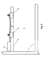
- Fig. 1 shows the usual arrangement of a lamp 4 for illuminating a room 3 with several floors 2 in a frame 1, as used for example according to the prior art for lighting poultry cages.
- Luminaire 4 and control electronics 22 are separated; this results in addition to a certain amount of space and an electrical uncertainty because of the large number of required electrical connections.
- the power supply unit 21 is electrical connections.
- the power supply unit 21 is arranged in the vicinity of the lamp 4 and the control electronics 22. In this arrangement, usually only a limited number of LEDs per control electronics 22 can be controlled.
- FIG. 2 shows an arrangement as is possible by means of the luminaire 5 according to the invention.
- Frame 1 with the floors 2 and the room to be illuminated 3 are unchanged from the arrangement shown in Fig. 1.
- the control electronics in the luminaire and the space requirement thereby reduced e.g. two lights 5 are arranged in principle the same space as in Fig. 1, so that a better illumination of the space 3 is made possible.
- the lights according to the invention can be installed in confined spaces.
- the lights 5 are powered by a central power supply 21; but their performance - not the space required by the luminaires - determines the number of luminaires that can be connected.
- the control of the lights can be done centrally; the control electronics is integrated according to the invention but in each lamp.
- FIG. 3a shows the internal structure of a luminaire 5 according to the invention.
- the luminous means used is a high-power LED 6. This is located on one side of the support plate 8, which can also serve as a heat sink.
- the control electronics 7 is arranged with terminals 10 for the power supply.
- the housing 11 of the lamp 5 is executed here in one piece. After installation of the parts, the housing 11 is filled with a potting compound 9, which is a good heat conductor and / or resistant to moisture.
- FIG. 3b shows another embodiment of a luminaire 5 according to the invention.
- the difference from the luminaire of FIG. 3a is that the current is supplied via cable 13 and not via terminals. The rest of the construction is unchanged.
- the housing 11 can be made in virtually any shape, with both metals and other materials, e.g. Plastics, can be used. In the latter case, attention must be paid to a certain thermal conductivity, since LEDs as semiconductor components are sensitive to heat and require a certain degree of cooling.
- the lamp 5 is waterproof.
- the lamp 5 may have a reflector 12 having an opening for the LED in the center.
- Fig. 4 shows a further carrier plate (also called print or board) with arranged thereon control electronics for the operation of the also mounted on the carrier plate high-power LED.
- the carrier plate shown is for attachment by means of a snap ring in a housing, as e.g. is shown in Figures 3a, 3b and in Figures 6a to 6c, suitable.
- This snap ring can be formed as part of the carrier plate, quasi integrated into the carrier plate.
- the electrical connections are again formed here as terminals, as they are already shown in Fig. 3a.
- this support plate can be encased directly without using a housing with synthetic resin, on the one hand the light emission, on the other hand, the heat dissipation must be secured.
- the LED on one side (bottom) of the specially developed for this lighting technology support plate which may for example consist of aluminum, attached.
- the control electronics is arranged, wherein in the embodiment shown, the support plate is coated with a special layer as a circuit board for the electronics and the power supply lines is also integrated on this page.
- the bottom can be equipped with sufficient heat dissipation with more than one LED.
- the support plate which represents a complete luminaire unit, except for a housing or a casing, can be inserted into a defined opening of a suitable housing by means of the (integrated) snap ring and optionally cast.
- the support plate can be cast around with the components arranged on it with plastic / synthetic resin, which can be almost any body shapes realized.
- the voltage supply of the LED lamp is in the safe low voltage range by means of DC or AC voltage through an external power supply unit, which may also have a control circuit for dimming the LED light (s).
- FIG. 7 shows an example of such an "external" supply unit.
- the control electronics in the LED light must of course be designed accordingly or adapted. Alternatively, an automatically adapting input circuit on the support plate can be realized, resulting in a universally usable LED light.
- FIG. 5 shows, by way of example, control electronics for operating an LED, as can be used for the invention.
- a rectifier 21 supplies the light-emitting diode 6 via a filter 22.
- a current limiter circuit 23 and a low-voltage bypass 24 are provided for operating the LED.
- a plurality of LEDs are arranged in a luminaire unit (see Fig. 6c), these can preferably be controlled by a common control electronics, resulting in a compact and economical construction.
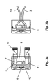
- Figures 6a to 6c show different housing shapes as they can be used for the invention.
- Fig. 6a a solid, thick-walled housing is shown, which has a bore with a defined diameter. This diameter is minimally larger than the diameter of a matching support plate, as shown in Fig. 4.
- a matching support plate as shown in Fig. 4.
- Fig. 6b shows a similar, but thin-walled embodiment as Fig. 6a.
- Fig. 6c finally, a housing for a double light is shown.
- two independent, possibly also independently controllable lights that is to say support plates with LEDs, can be accommodated therein.
- only one control electronics on a first carrier plate
- the second carrier plate then has only one LED with the corresponding connections and no control electronics. The attachment of the two support plates takes place as in Fig. 6a.
- the integration of the circuit or control electronics in the lamp itself is advantageous because the LED does not have to be operated by an external circuit, which error and interference sources are excluded by the previously used wire connections.
- the integration of the circuit shown and the LED requires no other connections than the power supply and result in an electrical unit that - except for the power supply - manages without external wiring and can thus be tested and operated as a functional unit.
- FIG. 7 the circuit of an external supply unit for operating one or preferably a plurality of LED lights is shown by way of example. If several LED lights are used, they can be connected in series, which keeps the wiring effort low. Of course, the power of the supply unit must correspond to the number and power of the LED lights to be fed.
- the driving of this output voltage control is effected by means of a DC voltage signal of 0-10V from a control unit (not shown), e.g. a computer, or simply by means of a knob arranged on the supply unit to manual control.
Landscapes
- Engineering & Computer Science (AREA)
- Microelectronics & Electronic Packaging (AREA)
- General Engineering & Computer Science (AREA)
- Physics & Mathematics (AREA)
- Optics & Photonics (AREA)
- Condensed Matter Physics & Semiconductors (AREA)
- General Physics & Mathematics (AREA)
- Computer Hardware Design (AREA)
- Power Engineering (AREA)
- Non-Portable Lighting Devices Or Systems Thereof (AREA)
- Arrangement Of Elements, Cooling, Sealing, Or The Like Of Lighting Devices (AREA)
Abstract
Description
Die Erfindung betrifft eine Leuchte für die Beleuchtung von Räumen, in denen eine kompakte, in sich geschlossene, kompakte, einfach zu handhabende und Platz sparende Leuchte bzw. ein derartiger Leuchtkörper erforderlich oder zweckentsprechend ist. Sie ist insbesondere für belastete Umgebungen, z.B. Feuchträume oder Tierzucht- und Tiermast-Anlage verwendbar, kann aber auch in gewöhnlichen, keinen besonderen Belastungen ausgesetzten Räumen eingesetzt werden.The invention relates to a luminaire for the lighting of rooms in which a compact, self-contained, compact, easy-to-use and space-saving lamp or such a filament is required or appropriate. It is particularly suitable for loaded environments, e.g. Humid rooms or animal husbandry and animal mast plant usable, but can also be used in ordinary, no special stress exposed rooms.
Es ist oft sinnvoll und manchmal notwendig, Kunstlicht mit einem kompakten Leuchtkörper mit wenig Stromverbrauch (und wenig Wärmeerzeugung) zu erzeugen, wobei es oft erwünscht ist, Leuchtkraft, Leuchtdichte oder Lichtmenge regeln zu können. Eine kompakte, Platz sparende Leuchte, die alle Bauteile in sich vereinigt, ist in solchen Fällen vorteilhaft.It is often useful and sometimes necessary to produce artificial light with a compact luminaire with low power consumption (and little heat generation), where it is often desirable to be able to regulate luminosity, luminance or amount of light. A compact, space-saving light, which unites all components, is advantageous in such cases.
Herkömmliche Leuchtmittel, z. B. Glühlampen, Sparlampen mit W14- oder W27-Fassungen, welche im Leistungsbereich von 7 und mehr Watt liegen, sind deswegen für die Beleuchtung der oben erwähnten Räume und Anlagen nicht ideal, weil ihre Fassungen und Gehäuse viel Platz beanspruchen und dazu oft gegen Schmutz und/oder Feuchtigkeit aufwendig geschützt werden müssen. Ausserdem sind viele herkömmliche Leuchtmittel relativ kurzlebig und reagieren empfindlich auf Vibrationen und Regelung (Dimmen). Insbesondere Sparlampen, die üblicherwesie als Quecksilber-Neiderdrucklampen ausgeführt sind, lassen sich nur mit erheblichem Aufwand dimmen.Conventional bulbs, z. As incandescent lamps, energy-saving lamps with W14 or W27 sockets, which are in the power range of 7 and more watts, are therefore not ideal for the illumination of the above-mentioned rooms and facilities, because their sockets and housing take up much space and often against dirt and / or moisture must be protected consuming. In addition, many conventional bulbs are relatively short-lived and are sensitive to vibration and regulation (dimming). In particular, energy-saving bulbs, the üblicherwesie designed as mercury-envy pressure lamps can be dimmed only with considerable effort.
So ist es beispielsweise bekannt, dass sich die Produktivität von in Stallungen oder Käfigen gehaltenen Tieren durch eine gesteuerte Beleuchtung erhöhen lässt. Eine entsprechend ausgestaltete Anlage für die Hühnerhaltung mit Einzelleuchten, also sozusagen mit "lokaler" Beleuchtung, ist in der WO-Publikation
In der
Aber auch in weniger kritischen Umgebungen ist eine kompakte, in sich geschlossene LED-Leuchte, die die erforderlichen Bauelemente für die Versorgung und die Regelung der als Leuchtmittel verwendeten LED enthält, aber dennoch wirtschaftlich hergestellt werden kann, von grossem Vorteil.But even in less critical environments is a compact, self-contained LED lamp, which contains the necessary components for the supply and control of the LED used as a light source, but can still be produced economically, of great advantage.
Bei der Verwendung von LEDs kann die Erzeugung der notwendigen Niederspannung in vorteilhafter Weise für eine Mehrzahl von LEDs zusammengefasst werden. Dann lassen sich die üblicherweise zur Erzeugung der erforderlichen Niederspannung verwendeten Transformatoren getrennt unterbringen und die Zuleitungen zu den LED-Leuchten führen nur ungefährliche Niederspannung.When using LEDs, the generation of the necessary low voltage can advantageously be combined for a plurality of LEDs. Then, the transformers commonly used to generate the required low voltage can be accommodated separately and the leads to the LED lights only lead to low voltage.
Aufgabe der Erfindung ist es daher, eine auch unter normalen wie auch schwierigen Umgebungsbedingungen brauchbare, einfach und sicher verwendbare Leuchte zu schaffen, die dazu noch preiswert in grosser Stückzahl hergestellt werden kann, wobei die Langlebigkeit der als Leuchtmittel benutzten LEDs voll genutzt werden soll. M.a.W., es soll eine möglichst universell verwendbare Leuchte geschaffen werden, die klein und kompakt ist, unempfindlich gegen Schmutz, Feuchtigkeit und Vibrationen ist, dazu geringen Stromverbrauch aufweist und mit sicherer Niederspannung zu betreiben und dazu noch einfach herzustellen ist.The object of the invention is therefore to provide a useful under normal as well as difficult environmental conditions, easy and safe to use lamp that can be made inexpensively in large quantities, the longevity of the LEDs used as bulbs is to be fully utilized. M.a.W., It is a universally applicable lamp to be created, which is small and compact, insensitive to dirt, moisture and vibration, has low power consumption and operate with safe low voltage and is also easy to make.
Zur Lösung dieser Aufgabe ist eine LED-Leuchte entsprechend dem Patentanspruch 1 ausgebildet. Der Leuchtkörper für Bauelemente und Systeme ist Gegenstand des Patentanspruches XXTo solve this problem, an LED light according to claim 1 is formed. The luminous element for components and systems is the subject of claim XX
Die Erfindung verwendet als Leuchtmittel Hochleistungs-LEDs, die derzeit mit bis zu 5 Watt Leistung angeboten werden. Solche LEDs sind findet man heute in vielen Beleuchtungsanwendungen, wobei, wie oben beschrieben, die Steuer-und Regelelektronik getrennt, z.B in separaten Gehäusen, untergebracht ist.The invention uses high-power LEDs as bulbs, which are currently offered with up to 5 watts of power. Such LEDs are found today in many lighting applications, where, as described above, the control and regulating electronics separated, for example, housed in separate housings.
Im Prinzip beruht die Erfindung auf der Idee, alle für die Steuerung der LED notwendigen Komponenten auf einem einzigen Print (einer gedruckten Schaltung oder einer Platine), auf dem vorzugsweise auch das Leuchtmittel, die LED, befestigt ist, zu integrieren und diesen Print mittels einer einfachem Snap-in Methode oder in ähnlich einfacher Weise in einem entsprechend gestalteten Gehäuse zu montieren. Dies kann anschliessend vergossen oder auf andere Weise abgedichtet werden. Dadurch sind die Nachteile der derzeitig auf dem Markt befindlichen LED-Leuchten behoben.In principle, the invention is based on the idea of integrating all the components necessary for the control of the LED on a single print (a printed circuit or a printed circuit board), on which the light source, the LED, is preferably also attached, and this print by means of a simple snap-in method or similarly easy to mount in a suitably designed housing. This can then be potted or sealed in some other way. This eliminates the disadvantages of LED lights currently on the market.
Alternativ kann auch der Print bzw. die Platine mit der montierten LED ohne Verwendung eines Gehäuses in Kunstharz vergossen werden, womit, durch den Wegfall des Gehäuses, eine sehr preiswerte und kompakte Leuchte entsteht.Alternatively, the print or the board with the mounted LED can be cast without using a housing in synthetic resin, with what, by the omission of the housing, a very inexpensive and compact lamp is created.
Eine solche Leuchte mit integrierter Steuerelektronik bietet weiterhin eine Vielzahl elektrischer Anschlussmöglichkeiten, z.B. die integrierte Befestigung und Stromzuführung mittels werkzeugloser Verbindung mit isoliertem Drahtseil, wie es heute für Innenraumbeleuchtung Mode ist. Hier können integrierte Schneidklemmen, Schraubklemmen, Stahlstifte oder isolierte Drahtenden verwendet werden.Such a lamp with integrated control electronics further offers a variety of electrical connection options, e.g. The integrated mounting and power supply by means of tool-free connection with insulated wire rope, as it is fashionable today for interior lighting. Here, integrated insulation displacement terminals, screw terminals, steel pins or insulated wire ends can be used.
Zudem bietet eine LED-Leuchte mit integrierter Steuerelektronik gemäss der Erfindung den Vorteil, dass praktisch jegliche Gehäuseform bzw. Raumform realisiert werden kann, wobei ästhetisch ansprechende Lösungen erarbeitet werden können.In addition, an LED lamp with integrated control electronics according to the invention has the advantage that virtually any housing shape or spatial form can be realized, with aesthetically pleasing solutions can be worked out.
Die weiteren Vorteile sind der geringe Energieverbrauch und die geringe Erwärmung von LED-Leuchten im Vergleich zu Leuchten, die mit Glühlampen bestückt sind, dazu kommt die ausserordentliche Kompaktheit, der hohe Wirkungsgrad, grosser Farbenvielfalt, lange Lebensdauer, und schliesslich die Unempfindlichkeit gegen Vibrationen, Schmutz und Feuchtigkeit.The other advantages are the low energy consumption and the low heating of LED lights compared to lights that are equipped with incandescent lamps, in addition to the extraordinary compactness, the high efficiency, great variety of colors, long life, and finally the insensitivity to vibration, dirt and moisture.
Die Erfindung bietet zudem einen wirtschaftlichen Vorteil. Obwohl Hochleistungs-LEDs teurer sind als herkömmliche Leuchtmittel, führt der geringere Stromverbrauch in kurzer Zeit zur Amortisation der grösseren Anschaffungskosten. Hinzu kommt die lange Lebensdauer der Leuchtmittel, die ein Vielfaches gewöhnlicher Glühlampen und immer noch ein Mehrfaches von handelsüblichen Stromsparlampen beträgt. Da in vielen Anwendungsbereichen das Wechseln einer Leuchte oder Lampe mit erheblichem Aufwand verbunden ist, lassen sich hier weitere Kosten einsparen.The invention also offers an economic advantage. Although high-power LEDs are more expensive than conventional bulbs, the lower power consumption in a short time to amortize the greater cost. In addition, there is the long life of the bulbs, which is a multiple of ordinary light bulbs and still a multiple of commercial energy saving lamps. Since changing a lamp or lamp is associated with considerable effort in many applications, it can save further costs here.
Durch ihre kompakte Bauweise und wegen ihres geringen Gewichts können die LED-Leuchten gemäss der Erfindung einfacher montiert werden als herkömmliche Leuchten. So ist neben Schraubverbindungen auch das Kleben oder eine Befestigung mittels Clips oder ähnlicher Vorrichtungen möglich. Wie oben erwähnt erfolgt die Verkabelung im Niederspannungbereich, womit eine Gefährdung von Mensch und Tier gering gehalten wird.Due to their compact design and their low weight, the LED lights are mounted according to the invention easier than conventional lights. Thus, in addition to screw and gluing or attachment by means of clips or similar devices possible. As mentioned above, the cabling is carried out in the low voltage range, whereby a risk to humans and animals is kept low.
Anhand der nachfolgenden Beschreibung von Ausführungsbeispielen im Zusammenhang mit den Zeichnungen wird die Erfindung näher erläutert. In den Zeichnungen zeigen:
- Fig. 1
- einige Leuchten herkömmlicher Bauart und ihre Anwendung;
- Fig. 2
- eine Leuchte gemäss der Erfindung und ihre Anwendung;
- Fign. 3a, 3b
- Schnittzeichnungen durch zwei Ausführungsformen einer Leuchte gemäss der Erfindung;
- Fig. 4
- eine Platine mit darauf angeordneter LED gemäss der Erfindung;
- Fig. 5
- ein Beispiel für die elektrische Schaltung zum Betrieb einer LED;
- Fign. 6a-6c
- Beispiele für verschiedene verwendbare Gehäuseformen; und
- Fig. 7
- ein Schaltungsbeispiel für die Erzeugung der Niederspannung und die Regelung/Dimmung von LED-Leuchten.
- Fig. 1
- some lights of conventional design and their application;
- Fig. 2
- a luminaire according to the invention and its application;
- FIGS. 3a, 3b
- Cross-sectional drawings through two embodiments of a luminaire according to the invention;
- Fig. 4
- a board with LED arranged thereon according to the invention;
- Fig. 5
- an example of the electrical circuit for operating an LED;
- FIGS. 6a-6c
- Examples of various usable housing shapes; and
- Fig. 7
- a circuit example for the generation of low voltage and the control / dimming of LED lights.
Fig. 1 zeigt die übliche Anordnung einer Leuchte 4 zur Beleuchtung eines Raums 3 mit mehreren Etagen 2 in einem Gestell 1, wie sie z.B. gemäss dem Stand der Technik zur Beleuchtung von Geflügelkäfigen benutzt wird. Leuchte 4 und Steuerelektronik 22 sind getrennt; dies ergibt neben einem gewissen Platzbedarf auch eine elektrische Unsicherheit wegen der Vielzahl von erforderlichen elektrischen Verbindungen. Die Stromversorgungseinheit 21 ist derlichen elektrischen Verbindungen. Die Stromversorgungseinheit 21 ist in der Nähe von Leuchte 4 und Steuerelektronik 22 angeordnet. Bei dieser Anordnung können üblicherweise nur eine beschränkte Anzahl LEDs pro Steuerelektronik 22 angesteuert werden.Fig. 1 shows the usual arrangement of a lamp 4 for illuminating a
Fig. 2 zeigt demgegenüber eine Anordnung, wie sie mittels der erfindungsgemässen Leuchte 5 möglich wird. Gestell 1 mit den Etagen 2 und dem zu beleuchtenden Raum 3 sind unverändert gegenüber der in Fig. 1 dargestellten Anordnung. Durch die Kompaktheit der Leuchte 5 und die Integration der Steuerelektronik in die Leuchte und den dadurch verringerten Platzbedarf können z.B. zwei Leuchten 5 im prinzipiell gleichen Raum wie in Fig. 1 angeordnet werden, so dass eine bessere Ausleuchtung des Raums 3 ermöglicht wird. Auch lassen sich die Leuchten gemäss der Erfindung bei beengten Platzverhältnissen einbauen. Die Leuchten 5 werden von einer zentralen Stromversorgung 21 elektrisch versorgt; allein deren Leistung - nicht der Platzbedarf der Leuchten - bestimmt die Anzahl der anschliessbaren Leuchten. Die Ansteuerung der Leuchten kann zentral erfolgen; die Steuerelektronik ist gemäss der Erfindung aber in jede Leuchte integriert.In contrast, FIG. 2 shows an arrangement as is possible by means of the
Fig. 3a zeigt den inneren Aufbau einer erfindungsgemässen Leuchte 5. Als Leuchtmittel wird eine Hochleistungs-LED 6 verwendet. Diese befindet sich auf der einen Seite der Trägerplatte 8, die auch als Kühlkörper dienen kann. Auf der anderen Seite der Trägerplatte 8 ist die Steuerelektronik 7 mit Klemmen 10 für die Stromzuführung angeordnet. Das Gehäuse 11 der Leuchte 5 ist hier einteilig ausgeführt. Nach dem Einbau der Teile wird das Gehäuse 11 mit einer Vergussmasse 9 ausgegossen, die ein guter Wärmeleiter und/oder resistent gegen Feuchtigkeit ist.3a shows the internal structure of a
Fig. 3b zeigt andere Ausführungsform einer erfindungsgemässen Leuchte 5. Der Unterschied zur Leuchte der Fig. 3a besteht darin, dass die Stromzuführung über Kabel 13 und nicht über Klemmen erfolgt. Der restliche Aufbau ist unverändert.FIG. 3b shows another embodiment of a
Das Gehäuse 11 kann in praktisch beliebigen Formen ausgeführt werden, wobei als Material wegen der geringen Wärmeentwicklung sowohl Metalle als auch andere Materialien, z.B. Kunststoffe, zum Einsatz kommen können. Bei letzteren muss auf eine gewisse Wärmeleitfähigkeit geachtet werden, da LEDs als Halbleiterbauelemente wärmeempfindlich sind und einer gewissen Kühlung bedürfen. Durch das Ausgiessen des Gehäuses mit entsprechender Vergussmasse 9 wird die Leuchte 5 wasserdicht. An der Vorderseite kann die Leuchte 5 einen Reflektor 12 aufweisen, der mittig eine Öffnung für die LED aufweist.The
Fig. 4 zeigt eine weitere Trägerplatte (auch Print oder Platine genannt) mit darauf angeordneter Steuerelektronik für den Betrieb der ebenfalls auf der Trägerplatte angebrachten Hochleistungs-LED. Die gezeigte Trägerplatte ist für eine Befestigung mittels eines Sprengrings in einem Gehäuse, wie es z.B. in den Figuren 3a, 3b und in den Figuren 6a bis 6c gezeigt ist, geeignet. Dieser Sprengring kann als Teil der Trägerplatte ausgebildet, quasi in die Trägerplatte intergriert sein. Die elektrischen Anschlüsse sind hier wieder als Klemmen ausgebildet, wie sie bereits in Fig. 3a gezeigt sind. Natürlich kann diese Trägerplatte auch ohne Verwendung eines Gehäuses unmittelbar mit Kunstharz ummantelt werden, wobei einerseits der Lichtaustritt, andererseits die Wärmeableitung gesichert sein müssen.Fig. 4 shows a further carrier plate (also called print or board) with arranged thereon control electronics for the operation of the also mounted on the carrier plate high-power LED. The carrier plate shown is for attachment by means of a snap ring in a housing, as e.g. is shown in Figures 3a, 3b and in Figures 6a to 6c, suitable. This snap ring can be formed as part of the carrier plate, quasi integrated into the carrier plate. The electrical connections are again formed here as terminals, as they are already shown in Fig. 3a. Of course, this support plate can be encased directly without using a housing with synthetic resin, on the one hand the light emission, on the other hand, the heat dissipation must be secured.
Bei der in Fig. 4 gezeigten Ausführungsform ist die LED auf einer Seite (Unterseite) der eigens für diese Leuchtentechnik entwickelten Trägerplatte, die z.B. aus Aluminium bestehen kann, angebracht. Auf der gegenüberliegenden Seite (Oberseite) der Trägerplatte ist die Steuerelektronik angeordnet, wobei in der gezeigten Ausführungsform die Trägerplatte mit einer speziellen Schicht als Leiterplatte für die Elektronik beschichtet wird und die Stromzuführungen ebenfalls auf dieser Seite integriert ist. Die Unterseite kann bei genügender Wärmeableitung auch mit mehr als einer LED bestückt werden.In the embodiment shown in Fig. 4, the LED on one side (bottom) of the specially developed for this lighting technology support plate, which may for example consist of aluminum, attached. On the opposite side (top) of the support plate, the control electronics is arranged, wherein in the embodiment shown, the support plate is coated with a special layer as a circuit board for the electronics and the power supply lines is also integrated on this page. The bottom can be equipped with sufficient heat dissipation with more than one LED.
Wie oben bereits angedeutet, kann die Trägerplatte, die bis auf ein Gehäuse bzw. eine Ummantelung eine in sich komplette Leuchten-Einheit darstellt, mittels des (integrierten) Sprengrings in eine definierte Öffnung eines geeigneten Gehäuses eingesetzt und ggf. vergossen werden. Alternativ kann die Trägerplatte mit den daruf angeordneten Bauteilen mit Kunststoff/Kunstharz umgossen werden, womit sich nahezu beliebige Körperformen realisieren lassen.As already indicated above, the support plate, which represents a complete luminaire unit, except for a housing or a casing, can be inserted into a defined opening of a suitable housing by means of the (integrated) snap ring and optionally cast. Alternatively, the support plate can be cast around with the components arranged on it with plastic / synthetic resin, which can be almost any body shapes realized.
Die Steuerelektronik auf der Oberseite der Trägerplatte kann z.B. folgende Funktionen ausführen:
- Regelung (Dimmen) der LED (mittels Spezial-IC);
- Konstantstrom-Regelung
- Gleichrichtung und Regelung der Versorgungsspannung für die LED.
- Regulation (dimming) of the LED (by means of special IC);
- Constant Current Regulation
- Rectification and regulation of the supply voltage for the LED.
Die Spannungsversorgung der LED-Leuchte erfolgt im ungefährlichen Niedervoltbereich mittels Gleich- oder Wechselspannung durch eine externe Stromversorgungseinheit, die auch eine Regelschaltung für die Dimmung der LED-Leuchte(n) aufweisen kann. In Fig. 7 ist ein Beispiel für eine solche "externe" Versorgungseinheit gezeigt. Die Steuerelektronik in der LED-Leuchte muss natürlich entsprechend ausgelegt bzw. angepasst werden. Alternativ ist auch eine sich automatisch anpassende Eingangsschaltung auf der Trägerplatte realisierbar, wodurch sich eine universell verwendbare LED-Leuchte ergibt.The voltage supply of the LED lamp is in the safe low voltage range by means of DC or AC voltage through an external power supply unit, which may also have a control circuit for dimming the LED light (s). FIG. 7 shows an example of such an "external" supply unit. The control electronics in the LED light must of course be designed accordingly or adapted. Alternatively, an automatically adapting input circuit on the support plate can be realized, resulting in a universally usable LED light.
In Fig. 5 ist beispielhaft eine Steuerelektronik zum Betrieb einer LED dargestellt, wie sie für die Erfindung verwendet werden kann. Die Versorgungsspannung beträgt im gezeigten Beispiel 12 V =, also eine auch unter kritischen Bedingungen ungefährliche Spannung. Ein Gleichrichter 21 versorgt über einen Filter 22 die Leuchtdiode 6. Weiterhin sind zum Betrieb der LED eine Strombegrenzerschaltung 23 und ein Niedrig-Spannungs-Bypass 24 vorgesehen.FIG. 5 shows, by way of example, control electronics for operating an LED, as can be used for the invention. In the example shown, the supply voltage is 12 V =, that is to say a voltage that is also harmless under critical conditions. A
Mit der Schaltung wird die über die Eingangsklemmen zugeführte Versorgungsspannung von 12 V = an die Betriebs-Gleichspannung der LED angepasst bzw. heruntergeregelt. Handelsübliche Hochleistungs-LEDs werden meist mit einem konstanten Gleichstrom betrieben, der mittels des gezeigten Schaltung erzeugt und geregelt wird. Stufenloses Dimmen kann beispielsweise mittels einer Phasenanschnitt-Regelung der Versorgungsspannung (im gezeigten Beispiel 12 V =) erfolgen. Dadurch kann die LED bis auf Null geregelt werden.With the circuit, the supplied via the input terminals supply voltage of 12 V = is adjusted to the DC operating voltage of the LED or down-regulated. Commercially available high-power LEDs are usually operated with a constant direct current, which is generated and regulated by means of the circuit shown. Stepless dimming can be done for example by means of a phase control of the supply voltage (12 V = in the example shown). This allows the LED to be controlled to zero.
Wenn in einer Leuchten-Einheit mehrere LEDs angeordnet sind (s. Fig. 6c), können diese vorzugsweise von einer gemeinsamen Steuerelektronik angesteuert werden, wodurch sich eine kompakte und wirtschaftliche Konstruktion ergibt.If a plurality of LEDs are arranged in a luminaire unit (see Fig. 6c), these can preferably be controlled by a common control electronics, resulting in a compact and economical construction.
Die Figuren 6a bis 6c zeigen verschiedene Gehäuseformen, wie sie für die Erfindung verwendet werden können. In Fig. 6a ist eine massives, dickwandiges Gehäuse dargestellt, das eine Bohrung mit einem definierten Durchmesser aufweist. Dieser Durchmesser ist minimal grösser als der Durchmesser einer dazu passenden Trägerplatte, wie sie in Fig. 4 dargestellt ist. Beim Einsetzen dieser Trägerplatte schnappt der vorgesehene Sprengring in die entsprechende Aussparung der Gehäusewand und hält damit die Trägerplatte definiert und unverrückbar in der vorgesehenen Position.Figures 6a to 6c show different housing shapes as they can be used for the invention. In Fig. 6a a solid, thick-walled housing is shown, which has a bore with a defined diameter. This diameter is minimally larger than the diameter of a matching support plate, as shown in Fig. 4. When inserting this support plate snaps the proposed snap ring in the corresponding recess of the housing wall and thus holds the support plate defined and immovable in the intended position.
Fig. 6b zeigt eine ähnliche, aber dünnwandige Ausführungsform wie Fig. 6a. In Fig. 6c schliesslich ist ein Gehäuse for eine Doppel-Leuchte dargestellt. Darin können einerseits zwei unabhängige, ggf. auch unabhängig regelbare Leuchten, sprich Trägerplatten mit LEDs, untergebracht werden. Andererseits kann auch nur eine Steuerelektronik (auf einer ersten Trägerplatte) vorgesehen sein, die beide LEDs ansteuert, wobei die LEDs vorzugsweise in Serie geschaltet sind. Die zweite Trägerplatte weist dann nur eine LED mit den entsprechenden Anschlüssen auf und keine Steuerelektronik. Die Befestigung der beiden Trägerplatten erfolgt wie in Fig. 6a.Fig. 6b shows a similar, but thin-walled embodiment as Fig. 6a. In Fig. 6c finally, a housing for a double light is shown. On the one hand, two independent, possibly also independently controllable lights, that is to say support plates with LEDs, can be accommodated therein. On the other hand, only one control electronics (on a first carrier plate) can be provided, which controls both LEDs, wherein the LEDs are preferably connected in series. The second carrier plate then has only one LED with the corresponding connections and no control electronics. The attachment of the two support plates takes place as in Fig. 6a.
Die Integration der Schaltung bzw. Steuerelektronik in die Leuchte selbst ist vorteilhaft, weil die LED nicht durch eine externe Schaltung betrieben werden muss, womit Fehler- und Störquellen durch die bisher verwendeten Drahtverbindungen ausgeschlossen werden. Die Integration der gezeigten Schaltung und der LED benötigt keine weiteren Anschlüsse als die Energiezuführungen und ergeben eine elektrische Einheit, die - bis auf die Stromzufuhr - ohne externe Beschaltung auskommt und damit als funktionstüchtige Einheit getestet und betrieben werden kann.The integration of the circuit or control electronics in the lamp itself is advantageous because the LED does not have to be operated by an external circuit, which error and interference sources are excluded by the previously used wire connections. The integration of the circuit shown and the LED requires no other connections than the power supply and result in an electrical unit that - except for the power supply - manages without external wiring and can thus be tested and operated as a functional unit.
In Fig. 7 ist beispielhaft die Schaltung einer externen Versorgungseinheit zum Betrieb einer oder vorzugsweise mehrerer LED-Leuchten dargestellt. Werden mehrere LED-Leuchten verwendet, so können diese in Reihe geschaltet werden, was den Verdrahtungsaufwand gering hält. Natürlich muss die Leistung der Versorgungseinheit der Anzahl und Leistung der zu speisenden LED-Leuchten entsprechen. Die Eingangsspannung der gezeigten Versorgungseinheit beträgt 230 V =, die Ausgangsspannung 12 V =. Diese Ausgangsspannung ist per Phasenanschnitt regelbar und erlaubt das Dimmen der angeschlossenen LED-Leuchte(n). Die Ansteuerung dieser Ausgangsspannungsregelung erfolgt mittels eines Gleichspannungssignals von 0 - 10V von einer (nicht gezeigten) Steuereinheit, z.B. einem Computer, oder einfach mittels eines an der Versorgungseinheit angeordneten Drehknopfs zu manuellen Steuerung.In FIG. 7, the circuit of an external supply unit for operating one or preferably a plurality of LED lights is shown by way of example. If several LED lights are used, they can be connected in series, which keeps the wiring effort low. Of course, the power of the supply unit must correspond to the number and power of the LED lights to be fed. The input voltage of the supply unit shown is 230 V =, the
Claims (13)
dadurch gekennzeichnet,
characterized,
dass die LED-Leuchte (5) als gegen äussere Einflüsse abgedichtete, insbesondere wasserdichte Einheit ausgebildet ist.LED luminaire according to claim 1, characterized
in that the LED lamp (5) is designed as a sealed, in particular watertight, unit against external influences.
dass mehrere LEDs (6) in einem gemeinsamen Gehäuse (11) oder einer gemeinsamen Ummantelung integriert sind.LED luminaire according to claim 1, characterized
in that a plurality of LEDs (6) are integrated in a common housing (11) or a common casing.
dass die mehreren LEDs (6) mit einer gemeinsamen Steuerelektronik ausgerüstet sind und betrieben werden.LED luminaire according to claim 3, characterized
that the plurality of LEDs (6) are equipped with common control electronics and are operated.
dadurch gekennzeichnet,
dass die Steuerelektronik zumindest einen Gleichrichter (21) und eine Strombegrenzerschaltung (23) einschliesst.LED luminaire according to at least one of the preceding claims,
characterized,
that the control electronics, at least a rectifier (21) and a current limiting circuit (23) includes.
dadurch gekennzeichnet,
dass das Gehäuse (11) und/oder eine das Gehäuse abdichtende Vergussmasse (9) oder die Ummantelung wärmeleitend sind.LED luminaire according to at least one of the preceding claims,
characterized,
that the housing (11) and / or a sealing compound sealing the housing (9) or the sheath are thermally conductive.
dadurch gekennzeichnet,
dass die Anschlüsse als Klemmanschlüsse (10) ausgebildet sind.LED luminaire according to at least one of the preceding claims,
characterized,
that the terminals are designed as clamping connections (10).
dadurch gekennzeichnet,
dass die Anschlüsse als Kabelanschlüsse (13) ausgebildet sind.LED lamp according to at least one of claims 1 to 6,
characterized,
that the terminals are formed as cables (13).
dadurch gekennzeichnet,
dass die Trägerplatte (8) auf einer Seite die Steuerelektronik, auf der anderen Seite die LED (6) aufweist.LED luminaire according to at least one of the preceding claims,
characterized,
that the carrier plate (8) on one side of the control electronics, on the other side having the LED (6).
dadurch gekennzeichnet,
dass im Gehäuse (11) eine mechanische Befestigungsvorrichtung vorgesehen ist, in die die Trägerplatte (8) rastbar positioniert werden kann.LED luminaire according to at least one of the preceding claims,
characterized,
in that a mechanical fastening device is provided in the housing (11) into which the carrier plate (8) can be snapped.
dass die mechanische Befestigungsvorrichtung an der Trägerplatte (8) als Sprengring und am Gehäuse (11) als zum Sprengring passende Aussparung, insbesondere als Ringnut, ausgebildet sind.LED luminaire according to claim 10, characterized
in that the mechanical fastening device is formed on the carrier plate (8) as a snap ring and on the housing (11) as a recess which fits the snap ring, in particular as an annular groove.
dass mindestens zwei der LED-Leuchten (5) von einer gemeinsamen Stromversorgungseinheit betrieben werden und vorzugsweise gemeinsam geregelt werden.Arrangement with a plurality of LED lights according to at least one of claims 1 to 11, characterized
that at least two of the LED lights (5) are operated by a common power supply unit and preferably regulated together become.
dass die Stromversorgungseinheit eine Helligkeitsregelung der angeschlossenen LED-Leuchten mittels einer Phasenanschnittregelung der Versorgungsspannung bewirkt.Arrangement with a plurality of LED lights according to claim 12, characterized in that
that the power supply unit causes a brightness control of the connected LED lights by means of a phase control of the supply voltage.
Applications Claiming Priority (1)
| Application Number | Priority Date | Filing Date | Title |
|---|---|---|---|
| DE102006031835A DE102006031835A1 (en) | 2006-07-07 | 2006-07-07 | LED light |
Publications (1)
| Publication Number | Publication Date |
|---|---|
| EP1876646A2 true EP1876646A2 (en) | 2008-01-09 |
Family
ID=38476966
Family Applications (1)
| Application Number | Title | Priority Date | Filing Date |
|---|---|---|---|
| EP07405190A Withdrawn EP1876646A2 (en) | 2006-07-07 | 2007-07-03 | LED lighting unit |
Country Status (2)
| Country | Link |
|---|---|
| EP (1) | EP1876646A2 (en) |
| DE (1) | DE102006031835A1 (en) |
Cited By (3)
| Publication number | Priority date | Publication date | Assignee | Title |
|---|---|---|---|---|
| EP2088369A1 (en) | 2008-02-07 | 2009-08-12 | Elmar Schrutek | Illuminant |
| WO2012059242A1 (en) * | 2010-11-04 | 2012-05-10 | Peter Hans Voss | Light fixture for livestock housing systems |
| WO2020152039A1 (en) * | 2019-01-23 | 2020-07-30 | Dr. Schneider Kunststoffwerke Gmbh | Lighting unit, illuminable component, and method for the production thereof |
Families Citing this family (1)
| Publication number | Priority date | Publication date | Assignee | Title |
|---|---|---|---|---|
| DE102012201616A1 (en) * | 2012-02-03 | 2013-08-08 | Tridonic Jennersdorf Gmbh | Plastic carrier for use with lead frame for light emitting diode chip of light emitting diode module, has mechanical connection for mounting optical elements, and insulation displacement contact for contacting light emitting diode chips |
-
2006
- 2006-07-07 DE DE102006031835A patent/DE102006031835A1/en not_active Ceased
-
2007
- 2007-07-03 EP EP07405190A patent/EP1876646A2/en not_active Withdrawn
Cited By (3)
| Publication number | Priority date | Publication date | Assignee | Title |
|---|---|---|---|---|
| EP2088369A1 (en) | 2008-02-07 | 2009-08-12 | Elmar Schrutek | Illuminant |
| WO2012059242A1 (en) * | 2010-11-04 | 2012-05-10 | Peter Hans Voss | Light fixture for livestock housing systems |
| WO2020152039A1 (en) * | 2019-01-23 | 2020-07-30 | Dr. Schneider Kunststoffwerke Gmbh | Lighting unit, illuminable component, and method for the production thereof |
Also Published As
| Publication number | Publication date |
|---|---|
| DE102006031835A1 (en) | 2008-01-17 |
Similar Documents
| Publication | Publication Date | Title |
|---|---|---|
| DE102008016788B4 (en) | Lighting system and method for providing both normal room lighting and emergency lighting | |
| EP2198196B1 (en) | Lamp | |
| DE112010002004T5 (en) | Modular LED lamp | |
| DE102010008876A1 (en) | Light source with array LEDs for direct operation on AC mains | |
| DE102011076128A1 (en) | Support system for light module e.g. LED module used in office, has light module that is mounted over support portion and contact with electric wires of support portion | |
| DE10026661A1 (en) | Universal LED illumination module for internal, external mains-powered lights has LEDs supplied with electrical power, driven via capacitor supply part directly connected to mains | |
| EP2031940B1 (en) | LED cluster assembly with constant current switch | |
| DE102015113638A1 (en) | Lighting device, illumination light source and power supply unit | |
| EP2307789B1 (en) | Lighting device with led | |
| EP1876646A2 (en) | LED lighting unit | |
| DE102010045297A1 (en) | Light, in particular tunnel light | |
| DE102012106165B4 (en) | lighting arrangement | |
| DE112016002776T5 (en) | Low profile ceiling light | |
| DE112016002778T5 (en) | Modular integrated lighting circuit | |
| DE202007015497U1 (en) | LED light, preferably as an emergency light, in particular on board ships | |
| DE102018209561B3 (en) | CONTROL DEVICE FOR AN LED LIGHT AND METHOD FOR CONTROLLING AN LED LIGHT | |
| DE202006010221U1 (en) | Light for aquarium, has multiple high-power LEDs mounted on heat sink by insulating screws, and dimmer for controlling brightness of LEDs, where heat sink has large base plate or base plate with attached ribs | |
| DE112013002008T5 (en) | Illumination light source | |
| DE102012002710A1 (en) | Lighting unit i.e. LED-tube, for use in fluorescent lamp for illuminating e.g. rooms, has control electronics comprising current controller and formed in transformer-free manner and/or formed with non-wet-electrolytic capacitors | |
| DE202006018835U1 (en) | LED-Light e.g. for outside lightening systems, has closed housing where LED is installed on plate and has outwardly arranged inlets | |
| DE102014114264A1 (en) | LED driver device, lighting device and LED driving device control circuit | |
| DE102016112457A1 (en) | LIGHTING CONTROL DEVICE, LIGHTING APPARATUS AND LIGHTING BODY | |
| DE102016104342B4 (en) | Lighting module and street or path light | |
| DE102020208809B4 (en) | Lighting arrangement with a tubular lighting device | |
| DE112016002781T5 (en) | Low-profile terminal |
Legal Events
| Date | Code | Title | Description |
|---|---|---|---|
| PUAI | Public reference made under article 153(3) epc to a published international application that has entered the european phase |
Free format text: ORIGINAL CODE: 0009012 |
|
| AK | Designated contracting states |
Kind code of ref document: A2 Designated state(s): AT BE BG CH CY CZ DE DK EE ES FI FR GB GR HU IE IS IT LI LT LU LV MC MT NL PL PT RO SE SI SK TR |
|
| AX | Request for extension of the european patent |
Extension state: AL BA HR MK YU |
|
| STAA | Information on the status of an ep patent application or granted ep patent |
Free format text: STATUS: THE APPLICATION IS DEEMED TO BE WITHDRAWN |
|
| 18D | Application deemed to be withdrawn |
Effective date: 20140201 |