EP1870996A1 - Circuit for feeding electric energy in a electric utility grid - Google Patents
Circuit for feeding electric energy in a electric utility grid Download PDFInfo
- Publication number
- EP1870996A1 EP1870996A1 EP06013068A EP06013068A EP1870996A1 EP 1870996 A1 EP1870996 A1 EP 1870996A1 EP 06013068 A EP06013068 A EP 06013068A EP 06013068 A EP06013068 A EP 06013068A EP 1870996 A1 EP1870996 A1 EP 1870996A1
- Authority
- EP
- European Patent Office
- Prior art keywords
- transformer
- circuit device
- inverter
- switching
- voltage
- Prior art date
- Legal status (The legal status is an assumption and is not a legal conclusion. Google has not performed a legal analysis and makes no representation as to the accuracy of the status listed.)
- Granted
Links
Images


Classifications
-
- H—ELECTRICITY
- H02—GENERATION; CONVERSION OR DISTRIBUTION OF ELECTRIC POWER
- H02M—APPARATUS FOR CONVERSION BETWEEN AC AND AC, BETWEEN AC AND DC, OR BETWEEN DC AND DC, AND FOR USE WITH MAINS OR SIMILAR POWER SUPPLY SYSTEMS; CONVERSION OF DC OR AC INPUT POWER INTO SURGE OUTPUT POWER; CONTROL OR REGULATION THEREOF
- H02M7/00—Conversion of ac power input into dc power output; Conversion of dc power input into ac power output
- H02M7/42—Conversion of dc power input into ac power output without possibility of reversal
- H02M7/44—Conversion of dc power input into ac power output without possibility of reversal by static converters
- H02M7/48—Conversion of dc power input into ac power output without possibility of reversal by static converters using discharge tubes with control electrode or semiconductor devices with control electrode
- H02M7/4807—Conversion of dc power input into ac power output without possibility of reversal by static converters using discharge tubes with control electrode or semiconductor devices with control electrode having a high frequency intermediate AC stage
-
- H—ELECTRICITY
- H02—GENERATION; CONVERSION OR DISTRIBUTION OF ELECTRIC POWER
- H02J—CIRCUIT ARRANGEMENTS OR SYSTEMS FOR SUPPLYING OR DISTRIBUTING ELECTRIC POWER; SYSTEMS FOR STORING ELECTRIC ENERGY
- H02J3/00—Circuit arrangements for ac mains or ac distribution networks
- H02J3/38—Arrangements for parallely feeding a single network by two or more generators, converters or transformers
- H02J3/381—Dispersed generators
-
- H—ELECTRICITY
- H02—GENERATION; CONVERSION OR DISTRIBUTION OF ELECTRIC POWER
- H02J—CIRCUIT ARRANGEMENTS OR SYSTEMS FOR SUPPLYING OR DISTRIBUTING ELECTRIC POWER; SYSTEMS FOR STORING ELECTRIC ENERGY
- H02J2300/00—Systems for supplying or distributing electric power characterised by decentralized, dispersed, or local generation
- H02J2300/10—The dispersed energy generation being of fossil origin, e.g. diesel generators
-
- H—ELECTRICITY
- H02—GENERATION; CONVERSION OR DISTRIBUTION OF ELECTRIC POWER
- H02J—CIRCUIT ARRANGEMENTS OR SYSTEMS FOR SUPPLYING OR DISTRIBUTING ELECTRIC POWER; SYSTEMS FOR STORING ELECTRIC ENERGY
- H02J2300/00—Systems for supplying or distributing electric power characterised by decentralized, dispersed, or local generation
- H02J2300/20—The dispersed energy generation being of renewable origin
- H02J2300/22—The renewable source being solar energy
- H02J2300/24—The renewable source being solar energy of photovoltaic origin
-
- H—ELECTRICITY
- H02—GENERATION; CONVERSION OR DISTRIBUTION OF ELECTRIC POWER
- H02J—CIRCUIT ARRANGEMENTS OR SYSTEMS FOR SUPPLYING OR DISTRIBUTING ELECTRIC POWER; SYSTEMS FOR STORING ELECTRIC ENERGY
- H02J2300/00—Systems for supplying or distributing electric power characterised by decentralized, dispersed, or local generation
- H02J2300/20—The dispersed energy generation being of renewable origin
- H02J2300/28—The renewable source being wind energy
-
- Y—GENERAL TAGGING OF NEW TECHNOLOGICAL DEVELOPMENTS; GENERAL TAGGING OF CROSS-SECTIONAL TECHNOLOGIES SPANNING OVER SEVERAL SECTIONS OF THE IPC; TECHNICAL SUBJECTS COVERED BY FORMER USPC CROSS-REFERENCE ART COLLECTIONS [XRACs] AND DIGESTS
- Y02—TECHNOLOGIES OR APPLICATIONS FOR MITIGATION OR ADAPTATION AGAINST CLIMATE CHANGE
- Y02E—REDUCTION OF GREENHOUSE GAS [GHG] EMISSIONS, RELATED TO ENERGY GENERATION, TRANSMISSION OR DISTRIBUTION
- Y02E10/00—Energy generation through renewable energy sources
- Y02E10/50—Photovoltaic [PV] energy
- Y02E10/56—Power conversion systems, e.g. maximum power point trackers
Abstract
Description
Die Erfindung betrifft eine Schaltungseinrichtung zum Einspeisen elektrischer Energie aus einer Energiequelle mit variabler Quellenspannung in ein elektrisches Energieversorgungsnetz (EVN) und mit einem Transformator mit einer Primär- und Sekundärseite, der eingangsseitig der Energiequelle und ausgangsseitig dem Energieversorgungsnetz zugeordnet ist,
Viele Quellen für elektrische Energie, wie Solargeneratoren, Windenergieanlagen mit Permanentmagnet-Generator, drehzahlvariable Verbrennungsmotoren, Brennstoffzellen, Batterien und dergleichen weisen häufig eine stark variierende Spannung und eine hohe Innenimpedanz auf. Derartige Energiequellen können eine Gleichspannung oder eine ein- oder dreiphasige Wechselspannung mit variabler Frequenz aufweisen.The invention relates to a circuit device for feeding electrical energy from an energy source with variable source voltage in an electrical power grid (EVN) and with a transformer having a primary and secondary side, the input side of the power source and the output side is assigned to the power grid,
Many sources of electrical energy, such as solar generators, permanent magnet generator wind turbines, variable speed internal combustion engines, fuel cells, batteries, and the like, often have a widely varying voltage and high internal impedance. Such energy sources may have a DC voltage or a single-phase or three-phase AC voltage with variable frequency.
Um elektrische Energie aus solchen Quellen in ein Energieversorgungsnetz einzuspeisen, sind Anpasseinrichtungen, wie zum Beispiel ein Solarwechselrichter, bekannt. Das Energieversorgungsnetz kann sowohl ein öffentliches Energieversorgungsnetz als auch ein Inselnetz für einen oder mehrere wenige Verbraucher sein.In order to feed electrical energy from such sources into a power grid, matching means, such as a solar inverter, are known. The power grid can be both a public power grid and an isolated grid for one or more consumers.
Eine solche bekannte Anpasseinrichtung hat die Aufgabe einer Anpassung der Spannung und der Frequenz an die Verhältnisse im Energieversorgungsnetz, in das eingespeist werden soll. Weiterhin dient die Einrichtung zur Herstellung eines möglichst optimalen Betriebspunktes für die Energiequelle, so dass ein maximaler Energieertrag erzielt wird. Dies ist auch unter dem Begriff Maximum Power Point Regelung bzw. MPP-Regelung bekannt.Such a known matching device has the task of adapting the voltage and the frequency to the conditions in the power supply network to be fed into the. Furthermore, the device is used to produce the best possible operating point for the energy source, so that a maximum energy yield is achieved. This is also known by the term maximum power point control or MPP control.
In vielen Fällen ist aufgrund technischer Erfordernisse oder aufgrund von länderspezifischen Regeln und Normen eine galvanische Trennung zwischen der Energiequelle und dem Versorgungsnetz erforderlich.In many cases, due to technical requirements or due to country-specific rules and standards, a galvanic isolation between the energy source and the supply network is required.
Bekannte Anpasseinrichtungen mit galvanischer Trennung haben jedoch einen deutlich schlechteren Wirkungsgrad als solche ohne galvanische Trennung.However, known matching devices with galvanic isolation have a significantly poorer efficiency than those without galvanic isolation.
Bekannt sind Schaltungsanordnungen mit einem NF-Transformator (Frequenz gleich der Frequenz im EVN). Der Energiequelle mit hohem Innenwiderstand wird ein einphasiger oder ein dreiphasiger Wechselrichter nachgeschaltet. Wenn die Energiequelle eine Gleichspannungsquelle wie z. B. ein Solargenerator oder eine Brennstoffzelle ist, wird der Wechselrichter direkt angeschlossen. Bei Wechselspannungsquellen, wie Wind oder Wasserkraftanlage mit Permanentmagnet-Generator, wird noch ein Gleichrichter zwischen-geschaltet. Der Wechselrichter ist als H-Brücke bei einphasigen Anlagen oder als Dreiphasenbrücke bei dreiphasigen Anlagen ausgeführt. Dem Wechselrichter wird ein Sinusfilter und ein Transformator nachgeschaltet. An die Transformatorsekundärseite ist das Energieversorgungsnetz angeschlossen.Circuit arrangements with a low-frequency transformer (frequency equal to the frequency in the EVN) are known. The energy source with high internal resistance is followed by a single-phase or three-phase inverter. If the power source is a DC voltage source such. B. is a solar generator or a fuel cell, the inverter is connected directly. For AC power sources, such as wind or hydro power plant with permanent magnet generator, a rectifier is still switched between. The inverter is designed as H-bridge for single-phase systems or as three-phase bridge for three-phase systems. The inverter is followed by a sine-wave filter and a transformer. The power supply network is connected to the transformer secondary side.
Bekannt sind auch Einrichtungen mit einem HF-Transformator (Frequenz höher als im EVN, typischerweise 1 KHz bis 1 MHz). Der Energiequelle mit hohem Innenwiderstand wird ein Hochfrequenz-Wechselrichter (HF-Wechselrichter) nachgeschaltet. Wenn die Energiequelle eine Gleichspannungsquelle wie ein Solargenerator oder eine Brennstoffzelle ist, wird der HF-Wechselrichter direkt angeschlossen. Bei Wechselspannungsquellen, wie z. B. Wind oder Wasserkraftanlagen, wird ein Gleichrichter zwischengeschaltet.Also known are devices with an RF transformer (frequency higher than in EVN, typically 1 kHz to 1 MHz). The energy source with high internal resistance is followed by a high-frequency inverter (HF inverter). If the power source is a DC power source such as a solar generator or a fuel cell, the RF inverter is connected directly. For alternating voltage sources, such. As wind or hydroelectric plants, a rectifier is interposed.
Der HF-Wechselrichter erzeugt eine hochfrequente Wechselspannung, die über den HF-Trafo auf die Sekundärseite transformiert wird. Dort wird die Wechselspannung durch einen Gleichrichter gleichgerichtet. Der Gleichrichter speist einen Gleichspannungszwischenkreis. Dem Gleichspannungszwischenkreis ist ein NF-Wechselrichter als H-Brücke bei einphasigen Anlagen oder als Dreiphasenbrücke bei dreiphasigen Anlagen nachgeschaltet. Über einen Sinusfilter wird das Versorgungsnetz mit dem NF-Wechselrichter verbunden.The HF inverter generates a high-frequency alternating voltage, which is transformed via the HF transformer to the secondary side. There, the AC voltage is rectified by a rectifier. The rectifier feeds a DC voltage intermediate circuit. The DC intermediate circuit is followed by a low-frequency inverter as H-bridge in single-phase systems or as a three-phase bridge in three-phase systems. The supply network is connected to the NF inverter via a sine-wave filter.
Weil die Energiequelle in den hier beschriebenen Fällen eine stark schwankende Spannung aufweist, muss oft noch ein Anpasssteller zwischen der Energiequelle und dem HF-Wechselrichter eingebaut werden, um den Gieichspannungszwischenkreis auf der Sekundärseite stabil zu halten. Dies ist insbesondere dann der Fall, wenn der HF-Wechselrichter als Resonanzumrichter ausgeführt ist. Resonanzumrichter besitzen zwar einen hohen Wirkungsgrad, können aber nicht zur Spannungsanpassung genutzt werden. Ein solcher Resonanzumrichter ist aus der
Wird der HF-Wechselrichter als hart schaltender Wechselrichter ausgeführt, kann er zu der erforderlichen Spannungsanpassung genutzt werden, weist aber einen schlechten Wirkungsgrad auf.If the HF inverter is designed as a hard-switching inverter, it can be used for the required voltage adjustment, but has a poor efficiency.
Bekannt sind auch solche Einrichtungen mit einem NF-Transformator. Das Transformatorübersetzungsverhältnis wird so gewählt, dass bei einer Spannung an der Energiequelle, die bei einem Solargenerator bei maximaler Einstrahlung und hoher Umgebungstemperatur und maximaler Netzspannung auftritt, noch Energie in ein EVN eingespeist werden kann. Der Strom auf der Primärseite des Transfomators ist jedoch sehr groß. Halbleiterschalter des NF-Wechselrichters müssen für diese hohen Ströme und gleichzeitig für die maximale Spannung der Energiequelle ausgelegt werden. Bedingt durch die Schaltverluste in den Halbleiterschaltern des NF-Wechselrichters steigen die Verluste. Außerdem ergeben sich weitere Nachteile. Der NF-Transformator ist groß und schwer. Es ergeben sich hohe Ströme auf der Transformatorprimärseite, weil das Übersetzungsverhältnis auf den Fall minimaler Spannung an der Energiequelle und maximaler Spannung im Energieversorgungsnetz angepasst sein muss. Zudem nehmen die Halbleiterverluste mit zunehmender Spannung an der Energiequelle zu.Also known are such devices with a NF transformer. The transformer ratio is chosen so that at a voltage at the power source, which occurs in a solar generator at maximum irradiation and high ambient temperature and maximum grid voltage, still energy can be fed into an EVN. However, the current on the primary side of the transfomator is very large. Semiconductor switches of the LF inverter must be designed for these high currents and at the same time for the maximum voltage of the energy source. Due to the switching losses in the semiconductor switches of the NF inverter, the losses increase. In addition, there are other disadvantages. The NF transformer is big and heavy. This results in high currents on the transformer primary side, because the transmission ratio must be adapted to the case of minimum voltage at the power source and maximum voltage in the power grid. In addition, the semiconductor losses increase with increasing voltage at the power source.
Bekannt sind auch Schaltungseinrichtungen dieser Art mit einem HF-Transfomator. Hierbei wird zwischen Schaltungen mit resonant schaltendem HF-Wechselrichter und hart schaltendem HF-Wechselrichter unterschieden.Circuit devices of this type with an RF transformer are also known. Here, a distinction is made between circuits with resonant switching RF inverter and hard-switching RF inverter.
Bei Schaltungen mit hart schaltenden HF-Wechselrichtern wird das Transformatorübersetzungsverhältnis des HF-Transformators so gewählt, dass zum Beispiel bei einem Solargenerator bei maximaler Einstrahlung und hoher Umgebungstemperatur und maximaler Netzspannung noch Energie in das Netz eingespeist werden kann. Damit ist der Strom auf der Primärseite des HF-Transformators jedoch ebenfalls sehr groß. Die Halbleiterschalter des HF-Wechselrichters müssen für diese hohen Ströme und gleichzeitig für die maximale Spannung der Energiequelle ausgelegt werden. Bedingt durch die Schaltverluste in den Halbleiterschaltern des HF-Wechselrichters steigen die Verluste mit zunehmender Spannung an der Energiequelle auch hier an. Nachteilig sind hohe Ströme auf der Primärseite des HF-Transformators, erhebliche Halbleiterverluste aufgrund des hart schaltenden Betriebs, weil in diesem Betriebspunkt große Schaltverluste in den Leistungshalbleitern entstehen, sowie ein geringer Wirkungsgrad der Anpasseinrichtung.In circuits with hard-switching RF inverters, the transformer ratio of the RF transformer is chosen so that, for example, in a solar generator with maximum irradiation and high ambient temperature and maximum mains voltage energy can be fed into the grid. However, the current on the primary side of the HF transformer is also very large. The semiconductor switches of the RF inverter must be designed for these high currents and at the same time for the maximum voltage of the power source. Due to the switching losses in the semiconductor switches of the RF inverter, the losses increase with increasing voltage at the power source here as well. Disadvantages are high currents on the primary side of the HF transformer, considerable semiconductor losses due to the hard switching operation, because at this operating point large switching losses occur in the power semiconductors, and a low efficiency of the adapter.
Bei einem resonant schaltenden HF-Wechselrichter ist, um eine stabile Spannung im Gleichspannungszwischenkreis nach dem Gleichrichter zur Verfügung zu stellen, eine zusätzliche Anpassstufe vorgesehen. Diese Anpassstufe wird vor dem HF-Wechselrichter oder nach der HF-Gleichrichtung geschaltet. Sie ist z. B. als Hoch- oder als Tiefsetzsteller ausgeführt. Eine solche Anpassstufe erfordert jedoch zusätzliche Kosten und benötigt zusätzlichen Platz. Zudem werden in einer solchen Stufe zusätzliche Verluste verursacht. Diese Variante benötigt also einen zusätzlichen Anpasssteller, wobei der Wirkungsgrad der Anpasseinrichtung durch einen solchen zusätzlichen Steller reduziert wird.In a resonant switching RF inverter, an additional matching stage is provided to provide a stable voltage in the DC link after the rectifier. This matching stage is switched before the HF inverter or after the HF rectification. It is z. B. executed as a high or as a buck converter. However, such an adjustment stage requires additional costs and requires additional space. In addition, additional losses are incurred in such a stage. This variant thus requires an additional adapter plate, wherein the efficiency of the adapter device is reduced by such an additional actuator.
Der Erfindung liegt die Aufgabe zugrunde, eine Schaltungseinrichtung der gattungsgemäßen Art mit hohem Wirkungsgrad bereitzustellen, die eine galvanische Trennung aufweist.The invention has for its object to provide a circuit device of the generic type with high efficiency, which has a galvanic isolation.
Diese Aufgabe wird erfindungsgemäß dadurch gelöst, dass mindestens zwei Transformatorabgriffe des Transformators oder mehrerer Transformatoren vorhanden sind und dass die Transformatorabgriffe mit Schaltelementen umschaltbar ausgebildet sind, um das TransformatorÜbersetzungsverhältnis zu verändern.This object is achieved in that at least two transformer taps of the transformer or multiple transformers are present and that the transformer taps are formed switchable with switching elements to change the transformer transformation ratio.
Durch die erfindungsgemäße Schaltungsanordnung ist es möglich, ohne eine zusätzliche Anpassschaltung mit zusätzlichen Halbleitern einen hohen Wirkungsgrad der Energiequelle zu erreichen. Durch die Veränderung des Übersetzungsverhältnisses kann eine Spannungsanpassung bei geringeren Strömen in den primärseitigen Halbleiter erzielt werden. Hierbei wird der Strom auf der Transformatorprimärseite im Gegensatz zum Stand der Technik nicht dadurch vorgegeben, dass das Übersetzungsverhältnis des Transformators auf die minimale Spannung der Energiequelle ausgelegt wird. Dadurch sinken die Umwandelungsverluste für Betriebszustände, bei denen die Eingangsspannung über der nominalen Eingangsspannung liegtBy the circuit arrangement according to the invention, it is possible to achieve a high efficiency of the energy source without an additional matching circuit with additional semiconductors. By changing the gear ratio, a voltage adjustment can be achieved at lower currents in the primary-side semiconductor. In this case, the current on the transformer primary side, unlike the prior art is not dictated by the fact that the transmission ratio of the transformer is designed for the minimum voltage of the power source. This reduces the conversion losses for operating conditions where the input voltage is above the nominal input voltage
Durch die erfindungsgemäße Schaltungseinrichtung wird eine Anpasseinrichtung mit galvanischer Trennung geschaffen, so dass einerseits Normen bzw. Sicherheitsanforderungen bei der Einspeisung entsprechend den gültigen Regeln der Technik erfüllt werden. Andererseits wird aber auch ein hoher Wirkungsgrad erzielt, wodurch eine hohe Wirtschaftlichkeit der Anpasseinrichtung gegeben ist und die Entwärmung der Anlage erleichtert wird.By the circuit device according to the invention a matching device is provided with galvanic isolation, so that on the one hand standards or safety requirements are met in the feed according to the valid rules of the art. On the other hand, however, a high efficiency is achieved, whereby a high efficiency of the adjustment device is given and the cooling of the system is facilitated.
Durch den Transformator mit mehreren Abgriffen oder mehreren Transformatoren mit mehreren Übersetzungsverhältnissen kann im Prinzip eine Spannungsanpassung zwischen der Energiequelle und dem Versorgungsnetz erreicht werden.By the transformer with multiple taps or multiple transformers with multiple ratios can be achieved in principle, a voltage adjustment between the power source and the supply network.
Durch eine solche Umschaltung des Transformatorübersetzungsverhältnisses kann in einfacher Weise auf eine zusätzliche leistungselektronische Anpassstufe verzichtet werden und es wird erreicht, dass der Wechselrichter in einem günstigen Arbeitspunkt betrieben werden kann, so dass er weniger Umwandlungsverluste verursacht.By such a switching of the transformer transmission ratio can be easily dispensed with an additional power electronic matching stage and it is achieved that the inverter can be operated in a favorable operating point, so that it causes less conversion losses.
In einer vorteilhaften Weiterbildung der erfindungsgemäßen Schaltungseinrichtung ist eine regelbarere Belastung auf der Primärseite vorgesehen, um die Spannung der Energiequelle zu begrenzen, während von einem Transformatorabgriff auf einen anderen Transformatorabgriff umgeschaltet wird. Während der Umschaltung zwischen den Abgriffen bzw. zwischen den Transformatoren ergibt sich eine kurze Zeitspanne, während der keine Energie übertragen werden kann. Diese Maßnahme dient dazu, die Spannung der Energiequelle während der Umschaltung konstant zu halten.In an advantageous embodiment of the circuit device according to the invention a more controllable load on the primary side is provided to limit the voltage of the power source, while being switched from one Transformatorabgriff to another Transformatorabgriff. During the switchover between the taps and between the transformers results in a short period during which no energy can be transmitted. This measure serves to keep the voltage of the energy source constant during the switchover.
Die Spannung der Energiequelle während der Umschaltung ändert sich nicht oder nur in dem gewünschten Umfang, wenn die regelbare Belastung als Widerstandschopper oder Bremschopper ausgeführt ist.The voltage of the power source during the changeover does not change, or only to the extent desired, when the controllable load is designed as a resistance chopper or brake chopper.
Zweckmäßigerweise sind zur Umschaltung zwischen den verschiedenen Transformatorabgriffen des Transformators oder zwischen den einzelnen Transformatorabgriffen der Transformatoren Relais, Schütze, Schalter, Trenner oder Halbleiterschaltern vorgesehen, so dass eine verlustarme automatische Umschaltung bewirkt werden kann.Conveniently, relays, contactors, switches, disconnectors or semiconductor switches are provided for switching between the various transformer taps of the transformer or between the individual Transformerabgriffen the transformers, so that a low-loss automatic switching can be effected.
Besonders günstig wirkt sich die Erfindung aus, wenn die Innenimpedanz der Energiequelle relativ hoch ist, wie bei einem Solargenerator. Mögliche Einsatzgebiete der Erfindung bieten sich auch beim Betrieb einer Brennstoffzelle, einer Batterie, einem Windkraftwerk mit permanentmagnetischem Generator, einer Verbrennungskraftmaschine mit permanentmagnetischem Generator oder einem Wasserkraftwerk mit permanentmagnetischem Generator.The invention has a particularly favorable effect if the internal impedance of the energy source is relatively high, as in the case of a solar generator. Possible fields of application of the invention also provide for the operation of a fuel cell, a battery, a wind power plant with a permanent magnetic generator, an internal combustion engine with permanent magnetic generator or a hydroelectric power plant with permanent magnetic generator.
In einer weiteren vorteilhaften Ausführung der Erfindung ist jeder Transformator ein NF-Transformator, dessen Betriebsfrequenz gleich der Frequenz des Energieversorgungsnetzes ist.In a further advantageous embodiment of the invention, each transformer is a low-frequency transformer whose operating frequency is equal to the frequency of the power supply network.
Das Transformatorübersetzungsverhältnis muss bei einem Solargenerator so gewählt werden, dass bei maximaler Einstrahlung und hoher Umgebungstemperatur eine maximale Netzspannung noch eingespeist werden kann.The transformer ratio must be selected in a solar generator so that at maximum irradiation and high ambient temperature, a maximum mains voltage can still be fed.
Vorteilhaft ist es auch, wenn jeder Transformator als HF-Transformator ausgeführt ist, dessen Frequenz größer als die Frequenz des Energieversorgungsnetzes ist.It is also advantageous if each transformer is designed as an RF transformer whose frequency is greater than the frequency of the power supply network.
Besonders vorteilhaft ist es, wenn den Transformatoren ein Wechselrichter vorgeschaltet ist, der Halbleiterschalter, insbesondere MOS Transistoren, IGBTs, GTOs oder Thyristoren umfasst. Die Schaltungseinrichtung ist so ausgeführt, dass der Transformator mit mehreren Abgriffen ausgeführt ist oder mehreren Transformatoren mit unterschiedlichen Übersetzungsverhältnissen verwendet werden, um eine grobe Spannungsanpassung zwischen der Energiequelle und dem Versorgungsnetz zu erreichen. Die Feinanpassung wird durch den NF-Wechselrichter erreicht, der ein ein- oder dreiphasiger Wechselrichter sein kann.It is particularly advantageous if the transformers are preceded by an inverter which comprises semiconductor switches, in particular MOS transistors, IGBTs, GTOs or thyristors. The circuit device is designed so that the transformer is designed with multiple taps or multiple transformers with different gear ratios are used to achieve a rough voltage adjustment between the power source and the supply network. The fine adjustment is achieved by the low frequency inverter, which can be a single or three phase inverter.
Vorteilhaft kann der Wechselrichter mit einem Resonanzkondensator, mit einem als HF-Transformator ausgeführten Transformator und mit einer Gleichrichterschaltung ausgeführt sein und so einen Resonanzumrichter bilden, wobei die Eigenfrequenz, die der Resonanzkondensator mit der Streuinduktivität des Transformators bildet, größer oder kleiner der Schaltfrequenz des Wechselrichters ist. Dadurch können die Schaltverluste in den Halbleiterschaltern des Resonanzumrichters gegenüber einem hart schaltenden Umrichter stark vermindert werden.Advantageously, the inverter may be implemented with a resonant capacitor, with a transformer designed as an HF transformer and with a rectifier circuit and thus form a resonant converter, wherein the natural frequency which forms the resonant capacitor with the stray inductance of the transformer is greater or less than the switching frequency of the inverter , As a result, the switching losses in the semiconductor switches of the resonant converter over a hard-switching inverter can be greatly reduced.
Weitere vorteilhafte Ausgestaltungen der Erfindung sind in den Unteransprüchen gekennzeichnet.Further advantageous embodiments of the invention are characterized in the subclaims.
Ein Ausführungsbeispiel der Erfindung wird anhand der Zeichnungen näher erläutert, wobei weitere vorteilhafte Weiterbildungen der Erfindung und Vorteile derselben beschrieben sind.An embodiment of the invention will be explained in more detail with reference to the drawings, wherein further advantageous developments of the invention and advantages thereof are described.
Es zeigen:
- Fig. 1
- eine Darstellung des Prinzips einer erfindungsgemäßen Schaltungseinrichtung mit einem Transformator,
- Fig. 2
- eine Darstellung des Prinzips einer erfindungsgemäßen Schaltungseinrichtung mit mehreren Transformatoren,
- Fig. 3
- eine erste Ausführungsform der Schaltungseinrichtung,
- Fig. 4
- Spannungsverläufe und andere Signale während eines Umschaltevorgangs,
- Fig. 5
- eine zweite Ausführungsform der Schaltungseinrichtung,
- Fig. 6
- eine dritte Ausführungsform der Schaltungseinrichtung,
- Fig. 7
- eine vierte Ausführungsform der Schaltungseinrichtung,
- Fig. 8
- eine fünfte Ausführungsform der Schaltungseinrichtung,
- Fig. 9
- zeigt eine weitere Ausführungsform der Schaltungseinrichtung für eine regelbare Belastung.
- Fig. 1
- a representation of the principle of a circuit device according to the invention with a transformer,
- Fig. 2
- a representation of the principle of a circuit device according to the invention with multiple transformers,
- Fig. 3
- a first embodiment of the circuit device,
- Fig. 4
- Voltage waveforms and other signals during a switching operation,
- Fig. 5
- a second embodiment of the circuit device,
- Fig. 6
- a third embodiment of the circuit device,
- Fig. 7
- A fourth embodiment of the circuit device,
- Fig. 8
- A fifth embodiment of the circuit device,
- Fig. 9
- shows a further embodiment of the circuit device for a controllable load.
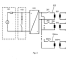
Fig. 1 zeigt das Prinzip einer erfindungsgemäßen Schaltungseinrichtung bzw. einer Anpasseinrichtung. Diese dient zum Einspeisen elektrischer Energie aus einer Energiequelle 101 mit variabler Quellenspannung in ein elektrisches Energieversorgungsnetz EVN. Die Energiequelle ist beispielsweise ein Solar- oder ein Photovoltaikgenerator. Die Schaltungseinrichtung weist einen Transformator 104 mit einer Primär- und Sekundärseite auf. Eingangsseitig ist dieser der Energiequelle 101 und ausgangsseitig dem Energieversorgungsnetz EVN zugeordnet. Wie Fig. 1 veranschaulicht, umfasst der Transformator 104 mehrere Abgriffe 205, 206, 204 + n. Das Übersetzungsverhältnis der Abgriffe 205, 206, 204 + n ist unterschiedlich.Fig. 1 shows the principle of a circuit device according to the invention or a matching device. This is used to supply electrical energy from a variable-voltage source of
Die Transformatorabgriffe 205, 206, 204 + n sind mit Schaltelementen 105, 106, 104 + n umschaltbar ausgebildet, um das TransformatorÜbersetzungsverhältnis zu verändern. Dadurch kann eine grobe Spannungsanpassung zwischen der Energiequelle 101 und dem Versorgungsnetz erreicht werden. Eine Feinanpassung kann z. B. durch einen einphasigen oder dreiphasigen Wechselrichter 103 erreicht werden, der direkt mit den Schaltelementen 105, 106, 104 + n verbunden ist.Transformer taps 205, 206, 204 + n are switchable with switching
Während der Umschaltung zwischen den Abgriffen 205, 206, 204 + n ,die beispielsweise mit Schützen oder Relais vorgenommen werden kann, ergibt sich eine kurze Zeitpanne, während der keine Energie übertragen werden kann. Um die Spannung der Energiequelle 101 während der Umschaltung konstant zu halten, wird sie während dieser Umschaltzeit durch insbesondere eine regelbare Belastung 102 belastet. Die Widerstandslast wird vorzugsweise mit Hilfe eines Widerstandschoppers so eingestellt, dass die Spannung der Energiequelle 101 sich während der Umschaltung nicht oder nur in einem gewünschten Umfang ändert.During the switching between the
Durch eine solche Umschaltung des Transformatorübersetzungsverhältnises kann auf eine zusätzliche leistungselektronische Anpassstufe verzichtet werden oder aber es wird erreicht, dass der Wechselrichter in einem günstigen Arbeitspunkt betrieben werden kann, so dass dieser weniger Umwandlungsverluste verursacht.By such a switching of the transformer transmission ratio can be dispensed with an additional power electronic matching stage or it is achieved that the inverter can be operated in a favorable operating point, so that it causes less conversion losses.
In Fig. 2 wird eine erfindungsgemäße Alternative mit mehreren Transformatoren 201, 202 und 200 +n mit unterschiedlichen Übersetzungsverhältnissen dargestellt. Jeder Transformator hat einen Abgriff, der mit einem Schaltelement 301, 302, 300 +n verbunden ist. Je nachdem, welches Schaltelement 301, 302, 300 +n geschaltet ist, ergibt sich ein bestimmtes Übersetzungsverhältnis.FIG. 2 shows an alternative according to the invention with a plurality of
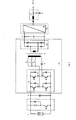
Eine erste Ausführungsform der Erfindung ist in Fig. 3 dargestellt. Als DC-Quelle mit hohem Innenwiderstand ist ein Solargenerator 1 vorgesehen. Die elektrische Energie des Generators 1 soll in ein Drehstromnetz (Energieversorgungsnetz EVN) gespeist werden. Dem ist eine Vollbrückenschaltung 4 mit vier Halbleiterschaltern nachgeschaltet. Parallel zu der Vollbrückenschaltung 4 ist ein Eingangskondensator 3 und die als Widerstandschopper ausgeführte Belastung 2 vorgesehen, wobei der Eingangskondensator 3 zwischen der Belastung und der Vollbrückenschaltung plaziert ist.A first embodiment of the invention is shown in FIG. As a DC source with high internal resistance, a
Die Vollbrückenschaltung 4 ist mit dem Transformator 9 primärseitig über einen Resonanzkondensator 5 verbunden. Eine Gleichrichterschaltung 10 ist dem Transformator 9 nachgeschaltet, also sekundärseitig angeordnet.The
Die Streuinduktivität des Transformators 9 bildet mit dem Kondensator 5 eine Resonanzfrequenz, die größer als die Schaltfrequenz der Vollbrückenschaltung 4 ist. Dadurch wird eine Resonanzumrichterschaltung 15 gebildet.The stray inductance of the
Mit Schützen 6, 7 und 8, die den einzelnen Transformatorabgriffen zugeordnet sind, kann das Übersetzungsverhältnis des Transformators 9 eingestellt werden. Genau eines der Schütze 6, 7 oder 8 ist bei Betrieb der Schaltung geschlossen.With
In einer anderen Ausführungsvariante könnten sich diese Schütze auch auf der Sekundärseite des Transformators befinden.In another embodiment, these contactors could also be located on the secondary side of the transformer.
Dem Resonanzumrichter 15 ist vorzugsweise ein Zwischenkreiskondensator 11 und ein Netzumrichter 12 nachgeschaltet. Der Netzumrichter 12 wird über den Netzfilter 13 mit dem Energieversorgungsnetz EVN verbunden. In Fig. 4 ist ein typischer Umschaltvorgang dargestellt.The
Es soll der Fall betrachtet werden, dass die MPP-Spannung des Solargenerators langsam absinkt, weil z.B. die Umgebungstemperatur zunimmt. In diesem Beispiel ist zunächst Schütz 7 geschlossen.Let us consider the case that the MPP voltage of the solar generator slowly decreases, because e.g. the ambient temperature increases. In this example,
Bedingt durch die Schaltungsanordnung mit dem Resonanzumrichter 15 ist die Eingangsspannung am Kondensator 3 mit dem Zwischenkreiskondensator 11 hart gekoppelt. Das heißt, unter Last verhalten sich beide Spannungen gemäß dem Transformatorübersetzungsverhältniss proportional zueinander.Due to the circuit arrangement with the
Sinkt nun die Spannung am Kondensator 11 so stark ab, dass die Grenze, bei der noch Netzeinspeisung möglich ist, erreicht wird, so muss das Transformatorübersetzungsverhältnis umgeschaltet werden.If the voltage at the
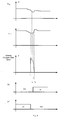
Der Schaltvorgang wird in Fig. 4 veranschaulicht. Hier sind die Spannungen am Kondensator 3, am Kondensator 11, die Leistung P am Chopperwiderstand sowie der Schaltzustand des Schützes 6 (S6) bzw. des Schützes 7 (S7) dargestellt.The switching operation is illustrated in FIG. 4. Here, the voltages at the
Zunächst wird der Widerstandschopper bzw. die Belastung 2 aktiviert und im weiteren Verlauf so geregelt, dass die Spannung am Kondensator 3 stabil bleibt. Zum Zeitpunkt t1 werden die Pulse des Resonanzumrichters 15 und des Netzumrichters 12 gesperrt. Dann wird Schütz 7 geöffnet. Danach wird Schütz 6 geschlossen.First, the resistance chopper or the
Zwischen t1 und t3 wird über den Widerstandschopper die Spannung am Kondansator 3 so weit abgesenkt, dass sie, berechnet mit dem neuen Trafoübersetzungsverhältnis, proportional der aktuellen Zwischenkreisspannung am Kondensator 11 ist. Zwischen t1 und t2 sinkt dabei die Schopperleistung etwas ab, weil der Solargenerator nicht mehr im MPP (Maximum Power Point) betrieben wird.Between t1 and t3, the voltage at the
Bei t3 werden die Pulse des Resonanzumrichters und des Netzumrichters freigegeben. Zwischen t3 und t4 sinkt die Leistung am Widerstandschopper ab. Die eingespeiste Leistung nimmt entsprechend zu. Der Netzumrichter wird wieder so geregelt, dass der MPP erneut erreicht wird. Dadurch steigt nun die Spannung am Kondensator 11 auf einen höheren Wert als vor dem Umschaltvorgang an. Im weiteren Verlauf dieses Beispiels steigt die Temperatur am Solargenerator weiter an, so dass die MPP-Spannung weiter absinkt, bis sie einen Endwert erreicht. Dadurch sinkt auch die Spannung am Kondensator 11 entsprechend. Ein weiterer Umschaltvorgang ist aber nicht erforderlich, da die Spannung am Kondensator 11 hoch genug ist, um eine Netzeinspeisung zu ermöglichen.At t3, the pulses of the resonant converter and the power converter are released. Between t3 and t4 the power at the resistance chopper decreases. The fed-in power increases accordingly. The network converter is regulated again so that the MPP is reached again. As a result, the voltage at the
Ein vorteilhaftes Merkmal der Erfindung ist die Regelung der Belastung 102 während der Umschaltphasen. Dadurch, dass bei resonant schaltenden Topologien, die Zwischenkreisspannung am Kondensator 11 proportional der Eingangsspannung ist, ist es zweckmäßig, nach einer Umschaltung die Eingangsspannung durch die Regelung der Belastung so einzustellen, dass sie der momentanen Spannung am Kondensator 11 multipliziert mit dem Übersetzungsverhältnis des Transformators entspricht. Dann kann der Resonanzumrichter 15 ohne zeitraubendes Anrampen sofort wieder mit vollem Pulsverhältnis eingeschaltet werden, ohne dass unerwünscht große Ausgleichsströme fließen.An advantageous feature of the invention is the regulation of the
Die regelbare Belastung 102 kann vor dem Einschalten der Wechselrichter 4 bzw. 14, 24 oder 34 (Fig. 5, Fig. 8, Fig. 6) dazu verwendet werden, die Eingangsspannung auf einen Wert abzusenken, der einen Betrieb des Wechselrichters 4 (14, 24 oder 34) ermöglicht, ohne dass die Anforderungen an die Spannungsfestigkeit der Halbleiterschalter in diesen Wechselrichtern überschritten wird. Dadurch kann ein Wechselrichter mit Halbleiterschaltern ausgerüstet werden, die zwar für den Betrieb im MPP nicht aber für den Betrieb bei Leerlauf der Eingangsspannungsquelle geeignet sind. Dadurch wiederum können Halbleiter mit niedrigerer Sperrspannung und damit günstigen Verlusten verwendet werden.The
Eine zweite Ausführungsvariante der Erfindung ist in Fig. 5 dargestellt. Der Resonanzumrichter 15 ist hier mit einer Halbbrückenschaltung 14 ausgeführt. Dabei kann der Kondensator 5 als Resonanzkondensator genutzt werden. Möglich ist auch, dass die Kondensatoren 31, 32 als Resonanzkondensatoren genutzt werden. Der Kondensator 5 kann auch ganz entfallen und durch eine Brücke ersetzt werden.A second embodiment of the invention is shown in Fig. 5. The
Der Wechselrichter 14 bildet mit dem Resonanzkondensator 5, mit den zusätzlich angeordneten Kondensatoren 31 und 32 sowie dem HF-Transformator 9 und der Gleichrichterschaltung 10 einen Resonanzumrichter. Die Eigenfrequenz, die die Kondensatoren 5, 31 und 32 mit der Streuinduktivität des Trafos bilden, ist größer oder kleiner der Schaltfrequenz des Wechselrichters 14. Dadurch sind die Schaltverluste in den Halbleiterschaltern des Resonanzumrichters 15 gegenüber einem hart schaltenden Umrichter stark vermindert.The
Die erfindungsgemäße Funktion der Schaltung gemäß Fig. 3 entspricht der in Fig. 1 und 2, so dass diese nicht näher beschrieben wird.The inventive function of the circuit according to FIG. 3 corresponds to that in FIGS. 1 and 2, so that it will not be described in detail.
Eine dritte Ausführungsvariante der Erfindung ist in Fig. 6 dargestellt. Der Resonanzumrichter ist hier primärseitig als Mittelpunktschaltung 34 ausgeführt, wobei zwei Halbleiterschalter eingesetzt werden. Der Resonanzkondensator 5 ist auf der Sekundärseite angeordnet. Auch die Schaltelemente 16, 17, 18 befinden sich auf der Sekundärseite.A third embodiment of the invention is shown in FIG. The resonant converter is designed on the primary side as a
Bei dieser Variante werden die Leistungsverluste auf der Primärseite auf ein Minimum reduziert. Dafür müssen Halbleiter mit einer höheren Sperrfähigkeit eingesetzt werden.In this variant, the power losses on the primary side are reduced to a minimum. This requires semiconductors with a higher blocking capability.
Der Wechselrichter 34, der Resonanzkondensator 5, ein HF-Transformator 9 und eine Gleichrichterschaltung 10 bilden einen Resonanzumrichter 15. Die Eigenfrequenz, die der Resonanzkondensator mit der Streuinduktivität des Trafos bildet, ist größer oder kleiner der Schaltfrequenz des Wechselrichters 34. Dadurch sind auch hier die Schaltverluste in den Halbleiterschaltern des Resonanzumrichters 15 gegenüber einem hart schaltenden Umrichter stark vermindert.The
Die erfindungsgemäße Funktion der Schaltung, die anhand der Figuren 1 und 2 beschrieben worden ist, ändert sich nicht, so dass diese nicht näher beschrieben wird.The inventive function of the circuit, which has been described with reference to Figures 1 and 2, does not change, so that it will not be described in detail.
Eine vierte Ausführungsvariante der Erfindung ist in Fig. 7 dargestellt. Der Resonanzumrichter 15 ist hier primärseitig als Mittelpunktschaltung 34 mit zwei Halbleiterschaltern ausgeführt. Eingesetzt werden Resonanzkondensatoren 41, 42, die als Bestandteil einer Halbbrückenschaltung 43 auf der Sekundärseite angeordnet sind. Auch die Umschalter 16, 17, 18 befinden sich auf der Sekundärseite.A fourth embodiment of the invention is shown in FIG. The
In dieser Ausführungsvariante werden die Verluste auf der Primärseite auf ein Minimum reduziert. Dafür müssen Halbleiter mit einer höheren Sperrfähigkeit eingesetzt werden.In this embodiment, the losses on the primary side are reduced to a minimum. This requires semiconductors with a higher blocking capability.
Eine fünfte Ausführungsvariante der Erfindung ist in Fig. 8 dargestellt. Auch hier ist als DC-Quelle mit hohem Innenwiderstand ein Solargenerator 1 vorgesehen. Diesem ist ein dreiphasiger Wechselrichter 24 mit einem Niederfrequenztransformator (NF-Transformator) 28 nachgeschaltet. Der Wechselrichter ist als Drehstrombrückenschaltung mit sechs Halbleiterschaltern ausgeführt. Parallel zu der DC-Quelle bzw. dem Solargenerator 1 sind der Eingangskondensator 3 und der Widerstandschopper bzw. die Belastung 2 vorgesehen.A fifth embodiment of the invention is shown in FIG. Again, a
Dem Transformator 28 kann drei Abgriffe haben, wie in Fig. 6 veranschaulicht ist. Es kann aber ein Transformator mit beliebig vielen Abgriffen verwendet werden. Im Beispiel nach Fig. 8 sind dem dreiphasigen Wechselrichter 24 drei Drehstromschütze 25, 26 und 27 zugeordnet. Diese haben jeweils drei Schaltkontakte, so dass neun Abgriffe vorhanden sind. Es kann zwischen drei unterschiedlichen Übersetzungsverhältnissen umgeschaltet werden. Jede Wicklung ist mit verschiedenen Abgriffen versehen, die den unterschiedlichen Schützen 25 bis 27 zugeordnet sind.The
Wenn jetzt die Spannung im Kondensator 3 so weit absinkt, dass eine Netzeinspeisung nicht mehr möglich ist, so wird der Widerstandschopper bzw. die Belastung 2 aktiviert. Der Wechselrichter 24 wird gesperrt. Dann wird das Drehstromschütz, das mit den bisher verwendeten Abgriffen verbunden ist, geöffnet. Ein anderes wird geschlossen. Der Wechselrichter 24 wird wieder aktiviert und übernimmt den Leistungsfluss vom Widerstandschopper 2. Wenn der Wechselrichter die volle Leistung übernommen hat, wird der Widerstandschopper wieder gesperrt. Vorteil dieser Ausführungsvariante ist die optimale Anpassung des Trafoübersetzungsverhältnisses an die aktuelle Spannung der Energiequelle. Dadurch steigt der Wirkungsgrad der Anpasseinrichtung. Der Transformator ist in Fig. 8 als YY-Transformator ausgeführt. Es kann aber auch ein DY-Transformator ein YD- oder ein DD-Transformator verwendet werden.Now, if the voltage in the
Die Streuinduktivität jeden Transformators kann durch eine oder mehrere zusätzliche Induktivitäten ergänzt werden, um die gewünschte Resonanzfrequenz zu erzielen.The leakage inductance of each transformer may be supplemented by one or more additional inductors to achieve the desired resonant frequency.
Weiterhin kann die Schaltung so betrieben werden, dass nach einer Umschaltung der Abgriffe eine Freigabe von Wechselrichterpulsen erfolgt, wobei die Eingangsspannung durch die Regelung der Belastung so eingestellt wird, dass sie der momentanen Spannung des eingesetzten Wechselrichterkondensators z.B. 11 multipliziert mit dem Übersetzungsverhältnis des Transformators entspricht.Furthermore, the circuit can be operated so that after switching the taps, a release of inverter pulses, wherein the input voltage is adjusted by the control of the load so that it corresponds to the instantaneous voltage of the inverter capacitor used, for. 11 multiplied by the transmission ratio of the transformer corresponds.
Möglich ist auch eine Ausführung derart, dass die Pulse des zugeordneten Wechselrichters 4, 14 oder 34 des Resonanzumrichters 15 direkt ohne Anrampen wieder mit vollem Pulsverhältnis eingeschaltet werden, nachdem die Eingangsspannung durch die Regelung der Belastung so eingestellt wurde, dass sie der momentanen Spannung am Wechselrichterkondensator 11 multipliziert mit dem Übersetzungsverhältnis des Transformators entspricht.Also possible is an embodiment such that the pulses of the associated
Vorteilhaft ist auch, wenn die Schaltungseinrichtung eine regelbare Belastung 102 auch dazu verwendet wird, vor dem Einschalten der Wechselrichter 4, 14, 24 oder 34 die Eingangsspannung auf einen Wert abzusenken, der einen Betrieb der Wechselrichter 4, 14, 24 oder 34 ermöglicht, ohne dass die Anforderungen an die Spannungsfestigkeit der Halbleiterschalter in diesen Wechselrichtern überschritten wird.It is also advantageous if the circuit means a
Figur 9 zeigt eine weitere Ausführungsvariante für die regelbare Belastung. Diese kann als Stromrichter 403 ausgeführt sein, der während der Umschaltphase die Energie der Energiequelle nutzt, um einen Energiespeicher 404, z. B. eine Batterie, zu laden. Dadurch geht die Energiequelle während der Umschaltphase nicht verloren.FIG. 9 shows a further embodiment variant for the controllable load. This can be designed as a
- 1.1.
- Solargeneratorsolar generator
- 2.Second
- Belastungburden
- 3.Third
- Eingangskondensatorinput capacitor
- 4.4th
- VollbrückenschaltungFull bridge circuit
- 5.5th
- Resonanzkondensatorresonant capacitor
- 6,7,86,7,8
- SchützeSagittarius
- 9.9th
- Transformatortransformer
- 10.10th
- GleichrichterschaltungRectifier circuit
- 11.11th
- ZwischenkreiskondensatorLink capacitor
- 12.12th
- Netzumrichterline converter
- 13.13th
- NetzfilterLine filter
- 14.14th
- Wechselrichterinverter
- 15.15th
- Resonanzumrichterschaltungresonant converter circuit
- 16, 17, 1816, 17, 18
- Schaltelementeswitching elements
- 2424
- Wechselrichterinverter
- 25, 26, 2725, 26, 27
- DrehstromschützeThree-phase contactors
- 2828
- NiederfrequenztransformatorLow frequency transformer
- 31,3231.32
- Kondensatorencapacitors
- 34.34th
- MittelpunktschaltungCenter circuit
- 41, 4241, 42
- Resonanzkondensatorenresonant capacitors
- 43.43rd
- HalbbrückenschaltungHalf-bridge circuit
- 101101
- Energiequelleenergy
- 102102
- Regelbare BelastungAdjustable load
- 103103
- Wechselrichterinverter
- 104104
- Transformatortransformer
- 105, 106, 104+n105, 106, 104 + n
- Schaltelementeswitching elements
- 201, 202, 200+n201, 202, 200 + n
- Transformatorentransformers
- 204, 205, 206+n204, 205, 206 + n
- Transformatorabgriffetransformer taps
- 301, 302, 300+n301, 302, 300 + n
- Schaltelementeswitching elements
- 402402
- Regelbare Belastung ausgeführt als LadeeinrichtungAdjustable load carried out as a charging device
Claims (24)
dadurch gekennzeichnet,
dass mindestens zwei Transformatorabgriffe (204, 205, 204 + n) des Transformators (104, 9, 28) oder mehrerer Transformatoren (201,202, 202+n) vorhanden sind und dass die Transformatorabgriffe (204, 205, 204 + n) mit Schaltelementen (105, 106, 104+n; 301, 302, 300+n) umschaltbar ausgebildet sind, um das TransformatorÜbersetzungsverhältnis zu verändern.Circuit device for supplying electrical energy from a variable source voltage energy source (102) to an electrical energy supply network (EVN), comprising a transformer having a primary and secondary side, which is assigned to the energy source on the input side and to the energy supply network on the output side,
characterized,
there are at least two transformer taps (204, 205, 204 + n) of the transformer (104, 9, 28) or several transformers (201, 202, 202 + n) and that the transformer taps (204, 205, 204 + n) are provided with switching elements ( 105, 106, 104 + n; 301, 302, 300 + n) are switchable to change the transformer ratio.
gekennzeichnet durch
eine regelbare Belastung (102) auf der Primärseite, um die Spannung der Energiequelle zu begrenzen, während von einem Transformatorabgriff auf einen anderen Transformatorabgriff umgeschaltet wird.Circuit device according to claim 1,
marked by
a controllable load (102) on the primary side to limit the voltage of the power source while switching from one transformer tap to another transformer tap.
dadurch gekennzeichnet, dass die regelbare Belastung (2) als Widerstandschopper oder Bremschopper ausgeführt ist.Circuit device according to Claim 2,
characterized in that the controllable load (2) is designed as a resistance chopper or brake chopper.
dadurch gekennzeichnet,
dass die regelbare Belastung (402) als Stromrichter (403) ausgeführt ist, der einen Energiespeicher (404) lädt.Circuit device according to Claim 2,
characterized,
in that the controllable load (402) is designed as a power converter (403) which charges an energy store (404).
dadurch gekennzeichnet,
dass jeder Transformator (104, 9, 28; 201, 202, 202 +n) als Einphasentransformatoren, als Zweiphasentransformatoren, Dreiphasentransformatoren oder als Mehrphasentransformatoren ausgeführt ist.Circuit device according to one of the preceding claims,
characterized,
that each transformer (104, 9, 28; 201, 202, 202 + n) is provided as a single-phase, as a two-phase transformers, three-phase transformers or as a multi-phase transformers executed.
dadurch gekennzeichnet,
dass zur Umschaltung zwischen den verschiedenen Transformatorabgriffen (204, 205, 204 + n) des Transformators (104, 9, 28) oder zwischen den einzelnen Transformatorabgriffen der Transformatoren (201, 202, 202 +n) Relais, Schütze, Schalter, Trenner oder Halbleiterschalter vorgesehen sind.Circuit device according to one of the preceding claims,
characterized,
that for switching between the various transformer taps (204, 205, 204 + n) of the transformer (104, 9, 28) or between the individual transformer taps of the transformers (201, 202, 202 + n) relays, contactors, switches, disconnectors or semiconductor switches are provided.
dadurch gekennzeichnet,
dass die Energiequelle (101) eine Gleichspannungsquelle ist.Circuit device according to one of the preceding claims,
characterized,
that the energy source (101) is a DC voltage source.
dadurch gekennzeichnet,
dass die Energiequelle (101) ein Solargenerator, eine Brennstoffzelle, eine Batterie, ein Windkraftwerk mit permanentmagnetischem Generator, eine Verbrennungsmaschine mit permanetmagnetischem Generator oder ein Wasserkraftwerk mit permanentmagnetischem Generator ist.Circuit device according to one of the preceding claims,
characterized,
in that the energy source (101) is a solar generator, a fuel cell, a battery, a wind turbine with a permanently magnetic generator, a permanent magnet generator or a hydro generator with a permanent magnet generator.
dadurch gekennzeichnet,
dass das Energieversorgungsnetz (EVN) ein öffentliches Energieversorgungsnetz ist oder ein Inselnetz mit einem oder mehreren Verbrauchern ist.Circuit device according to one of the preceding claims,
characterized,
that the energy supply network (EVN) is a public power grid or is an island network with one or more consumers.
dadurch gekennzeichnet,
dass jeder Transformator ein NF Transformator ist, dessen Betriebsfrequenz gleich der Frequenz des Energieversorgungsnetzes ist.Circuit device according to one of the preceding claims,
characterized,
that each transformer is a NF transformer whose operating frequency is equal to the frequency of the power supply network.
dadurch gekennzeichnet,
dass jeder Transformator als HF-Transformator ausgeführt ist und dessen Frequenz größer als die Frequenz des Energieversorgungsnetzes ist.Circuit device according to one of Claims 1 to 10,
characterized,
that each transformer is designed as an RF transformer and whose frequency is greater than the frequency of the power supply network.
dadurch gekennzeichnet,
dass dem Transformator oder den Transformatoren ein Wechselrichter (103, 14, 34, 24) vorgeschaltet ist, der Halbleiterschalter umfasst, insbesondere MOS Transistoren, IGBTs, GTOs oder Thyristoren umfasst.Circuit device according to one of the preceding claims,
characterized,
in that the transformer or transformers are preceded by an inverter (103, 14, 34, 24) which comprises semiconductor switches, in particular MOS transistors, IGBTs, GTOs or thyristors.
dadurch gekennzeichnet,
dass der Wechselrichter (103, 14, 34, 24) ein einphasiger oder ein dreiphasiger Wechselrichter ist.Circuit device according to Claim 12,
characterized,
that the inverter (103, 14, 34, 24) is a single-phase or a three-phase inverter.
dadurch gekennzeichnet,
dass der Wechselrichter (4) mindestens einen Resonanzkondensator (5; 31, 32; 41, 42) sowie einen als HF-Transformator (9) ausgeführten Transformator und eine Gleichrichterschaltung (10, 43) umfasst und einen Resonanzumrichter (15) bildet, wobei die Eigenfrequenz, die der Resonanzkondensator mit der Streuinduktivität des Transformators (9) bildet, größer oder kleiner der Schaltfrequenz des Wechselrichters ist.Circuit device according to claim 12 or 13,
characterized,
in that the inverter (4) comprises at least one resonance capacitor (5; 31, 32; 41, 42) and a transformer designed as an HF transformer (9) and a rectifier circuit (10, 43) and forms a resonant converter (15) Natural frequency, which forms the resonant capacitor with the leakage inductance of the transformer (9) is greater or less than the switching frequency of the inverter.
dadurch gekennzeichnet,
dass ein oder mehrere Resonanzkondensatoren (5; 41, 42) am Transformator (9) sekundärseitig angeordnet sind.Circuit device according to Claim 14,
characterized,
in that one or more resonance capacitors (5; 41, 42) are arranged on the secondary side of the transformer (9).
dadurch gekennzeichnet,
dass ein oder mehrere Resonanzkondensatoren (5) am Transformator (9) primärseitig angeordnet sind.Circuit device according to Claim 14,
characterized,
in that one or more resonance capacitors (5) are arranged on the primary side of the transformer (9).
dadurch gekennzeichnet,
dass der Wechselrichter (14) eine Halbbrückenschaltung aufweist.Circuit device according to one of Claims 12 to 14,
characterized,
that the inverter (14) comprises a half-bridge circuit.
dadurch gekennzeichnet,
dass der Wechselrichter (14) eine Vollbrückenschaltung aufweist.Circuit device according to one of Claims 12 to 14,
characterized,
that the inverter (14) comprises a full bridge circuit.
dadurch gekennzeichnet,
dass die Streuinduktivität jeden Transformators durch eine oder mehrere zusätzliche Induktivitäten ergänzt wird, um die gewünschte Resonanzfrequenz zu erzielen.Circuit device according to one of the preceding claims,
characterized,
that the leakage inductance of each transformer is complemented by one or more additional inductances in order to achieve the desired resonant frequency.
dadurch gekennzeichnet,
dass die Schaltelemente zur Umschaltung zwischen den einzelnen Transformatorabgriffen oder zwischen den einzelnen Transformatoren auf der Primärseite des Transformators oder der Transformatoren angeordnet sind.Circuit device according to one of the preceding claims,
characterized,
that the switching elements for switching between the different transformer taps or between the different transformers on the primary side of the transformer or of the transformers are arranged.
dadurch gekennzeichnet,
dass die Schaltelemente zur Umschaltung zwischen den einzelnen Transformatorabgriffen oder zwischen den einzelnen Transformatoren auf der Sekundärseite des Transformators oder der Transformatoren angeordnet sind.Circuit device according to one of the preceding claims,
characterized,
that the switching elements are arranged for switching between the individual transformer taps or between the individual transformers on the secondary side of the transformer or of the transformers.
gekennzeichnet durch
eine Ausführung derart, dass nach einer Umschaltung und vor einer Freigabe von Wechselrichterpulsen, die Eingangspannung durch die Regelung der Belastung so eingestellt wird, dass sie der momentanen Spannung eines Wechselrichterkondensators (11) multipliziert mit dem Übersetzungsverhältnis des Transformators entspricht.Circuit device according to one of Claims 12 to 19,
marked by
an embodiment such that, after switching and before enabling of inverter pulses, the input voltage is adjusted by the regulation of the load so that it corresponds to the instantaneous voltage of an inverter capacitor (11) multiplied by the transmission ratio of the transformer.
gekennzeichnet durch
eine Ausführung derart, dass die Pulse des zugeordneten Wechselrichters (4, 14 oder 34) des Resonanzumrichters 15 direkt ohne Anrampen wieder mit vollem Pulsverhältnis eingeschaltet werden, nachdem die Eingangsspannung durch die Regelung der Belastung so eingestellt wurde, dass sie der momentanen Spannung am Wechselrichterkondensator (11) multipliziert mit dem Übersetzungsverhältnis des Transformators entspricht.Circuit device according to claim 19,
marked by
an embodiment such that the pulses of the associated inverter (4, 14 or 34) of the resonant converter 15 are switched on again directly without ramping up with full pulse ratio, after the input voltage has been adjusted by the regulation of the load so that it corresponds to the instantaneous voltage at the inverter capacitor ( 11) multiplied by the transmission ratio of the transformer.
gekennzeichnet durch
eine Ausführung derart, dass die Schaltungseinrichtung eine regelbare Belastung (102) auch dazu verwendet wird, vor dem Einschalten der Wechselrichter (4, 14, 24 oder 34) die Eingangsspannung auf einen Wert abzusenken, der einen Betrieb der Wechselrichter (4, 14, 24 oder 34) ermöglicht, ohne dass die Anforderungen an die Spannungsfestigkeit der Halbleiterschalter in diesen Wechselrichtern überschritten wird.Circuit device according to one of the preceding claims,
marked by
an embodiment such that the circuit means a controllable load (102) is also used to lower the input voltage to a value prior to switching on the inverters (4, 14, 24 or 34) to a value of operation of the inverters (4, 14, 24 or 34) without exceeding the dielectric strength requirements of the semiconductor switches in these inverters.
Priority Applications (4)
| Application Number | Priority Date | Filing Date | Title |
|---|---|---|---|
| EP06013068A EP1870996B1 (en) | 2006-06-24 | 2006-06-24 | Circuit for feeding electric energy in a electric utility grid |
| AT06013068T ATE446603T1 (en) | 2006-06-24 | 2006-06-24 | CIRCUIT FOR FEEDING ELECTRICAL ENERGY INTO AN ELECTRICAL SUPPLY NETWORK |
| ES06013068T ES2332010T3 (en) | 2006-06-24 | 2006-06-24 | CIRCUIT FOR THE POWER SUPPLY OF ELECTRICAL ENERGY TO A NETWORK OF ELECTRICAL DISTRIBUTION. |
| DE502006005188T DE502006005188D1 (en) | 2006-06-24 | 2006-06-24 | Circuit for feeding electrical energy into an electrical supply network |
Applications Claiming Priority (1)
| Application Number | Priority Date | Filing Date | Title |
|---|---|---|---|
| EP06013068A EP1870996B1 (en) | 2006-06-24 | 2006-06-24 | Circuit for feeding electric energy in a electric utility grid |
Publications (2)
| Publication Number | Publication Date |
|---|---|
| EP1870996A1 true EP1870996A1 (en) | 2007-12-26 |
| EP1870996B1 EP1870996B1 (en) | 2009-10-21 |
Family
ID=37398803
Family Applications (1)
| Application Number | Title | Priority Date | Filing Date |
|---|---|---|---|
| EP06013068A Not-in-force EP1870996B1 (en) | 2006-06-24 | 2006-06-24 | Circuit for feeding electric energy in a electric utility grid |
Country Status (4)
| Country | Link |
|---|---|
| EP (1) | EP1870996B1 (en) |
| AT (1) | ATE446603T1 (en) |
| DE (1) | DE502006005188D1 (en) |
| ES (1) | ES2332010T3 (en) |
Cited By (6)
| Publication number | Priority date | Publication date | Assignee | Title |
|---|---|---|---|---|
| EP2148417A1 (en) | 2008-07-22 | 2010-01-27 | SMA Solar Technology AG | Inverter apparatus for a photovoltaic generator with a plurality of inverters being serially coupled at their input side |
| EP2187510A1 (en) * | 2008-11-15 | 2010-05-19 | SMA Solar Technology AG | Inverter start up switch |
| WO2011066121A1 (en) * | 2009-11-25 | 2011-06-03 | American Superconductor Corporation | Reducing photovoltaic array voltage during inverter re-enablement |
| US7989983B2 (en) | 2009-11-24 | 2011-08-02 | American Superconductor Corporation | Power conversion systems |
| WO2012062662A1 (en) * | 2010-11-08 | 2012-05-18 | Sma Solar Technology Ag | Method for operation of a photovoltaic installation for feeding electrical power into a medium-voltage power supply grid |
| DE102011083720A1 (en) * | 2011-09-29 | 2013-04-04 | Siemens Aktiengesellschaft | Apparatus for connecting solar generator to electrical alternating current (AC) system of photovoltaic plant, has transformer with changeable transmission ratio, to transform AC voltages of different sizes to preset AC supply voltage |
Citations (5)
| Publication number | Priority date | Publication date | Assignee | Title |
|---|---|---|---|---|
| JPH0715971A (en) | 1993-06-25 | 1995-01-17 | Toshiba Fa Syst Eng Kk | Power conversion device |
| WO2001086797A1 (en) * | 2000-05-09 | 2001-11-15 | Williamson Floyd L | Method and apparatus for power supply and conversion |
| US6370050B1 (en) * | 1999-09-20 | 2002-04-09 | Ut-Batelle, Llc | Isolated and soft-switched power converter |
| GB2386208A (en) * | 2002-03-08 | 2003-09-10 | Visteon Global Tech Inc | Low-frequency, low power switching voltage pre-regulator circuit |
| EP1458084A2 (en) | 2003-03-13 | 2004-09-15 | HONDA MOTOR CO., Ltd. | Two-way DC-DC converter |
-
2006
- 2006-06-24 ES ES06013068T patent/ES2332010T3/en active Active
- 2006-06-24 EP EP06013068A patent/EP1870996B1/en not_active Not-in-force
- 2006-06-24 AT AT06013068T patent/ATE446603T1/en active
- 2006-06-24 DE DE502006005188T patent/DE502006005188D1/en active Active
Patent Citations (5)
| Publication number | Priority date | Publication date | Assignee | Title |
|---|---|---|---|---|
| JPH0715971A (en) | 1993-06-25 | 1995-01-17 | Toshiba Fa Syst Eng Kk | Power conversion device |
| US6370050B1 (en) * | 1999-09-20 | 2002-04-09 | Ut-Batelle, Llc | Isolated and soft-switched power converter |
| WO2001086797A1 (en) * | 2000-05-09 | 2001-11-15 | Williamson Floyd L | Method and apparatus for power supply and conversion |
| GB2386208A (en) * | 2002-03-08 | 2003-09-10 | Visteon Global Tech Inc | Low-frequency, low power switching voltage pre-regulator circuit |
| EP1458084A2 (en) | 2003-03-13 | 2004-09-15 | HONDA MOTOR CO., Ltd. | Two-way DC-DC converter |
Cited By (11)
| Publication number | Priority date | Publication date | Assignee | Title |
|---|---|---|---|---|
| EP2148417A1 (en) | 2008-07-22 | 2010-01-27 | SMA Solar Technology AG | Inverter apparatus for a photovoltaic generator with a plurality of inverters being serially coupled at their input side |
| EP2187510A1 (en) * | 2008-11-15 | 2010-05-19 | SMA Solar Technology AG | Inverter start up switch |
| US8379418B2 (en) | 2008-11-15 | 2013-02-19 | Sma Solar Technology Ag | Power converter start-up circuit |
| US7989983B2 (en) | 2009-11-24 | 2011-08-02 | American Superconductor Corporation | Power conversion systems |
| WO2011066081A3 (en) * | 2009-11-24 | 2011-11-24 | American Superconductor Corporation | Power conversion systems |
| CN102782974A (en) * | 2009-11-24 | 2012-11-14 | 美国超导公司 | Power conversion systems |
| WO2011066121A1 (en) * | 2009-11-25 | 2011-06-03 | American Superconductor Corporation | Reducing photovoltaic array voltage during inverter re-enablement |
| US9172312B2 (en) | 2009-11-25 | 2015-10-27 | American Superconductor Corporation | Reducing photovoltaic array voltage during inverter re-enablement |
| WO2012062662A1 (en) * | 2010-11-08 | 2012-05-18 | Sma Solar Technology Ag | Method for operation of a photovoltaic installation for feeding electrical power into a medium-voltage power supply grid |
| US9525287B2 (en) | 2010-11-08 | 2016-12-20 | Sma Solar Technology Ag | Inverter system and method for operation of a photovoltaic installation for feeding electrical power into a medium-voltage power supply grid |
| DE102011083720A1 (en) * | 2011-09-29 | 2013-04-04 | Siemens Aktiengesellschaft | Apparatus for connecting solar generator to electrical alternating current (AC) system of photovoltaic plant, has transformer with changeable transmission ratio, to transform AC voltages of different sizes to preset AC supply voltage |
Also Published As
| Publication number | Publication date |
|---|---|
| ES2332010T3 (en) | 2010-01-22 |
| ATE446603T1 (en) | 2009-11-15 |
| DE502006005188D1 (en) | 2009-12-03 |
| EP1870996B1 (en) | 2009-10-21 |
Similar Documents
| Publication | Publication Date | Title |
|---|---|---|
| EP1956703B1 (en) | Device for feeding electrical energy from an energy source | |
| EP3172823B1 (en) | Dc-to-dc converter comprising a transformer | |
| EP2187510B1 (en) | Inverter start up switch | |
| DE102007028077B4 (en) | Device for feeding electrical energy into a power supply network and DC-DC converter for such a device | |
| EP1311058B1 (en) | Frequency power converter | |
| EP3496259B1 (en) | Electrical converter system | |
| EP2148417B1 (en) | Inverter apparatus for a photovoltaic generator with a plurality of inverters being serially coupled at their input side | |
| DE102011011329A1 (en) | Boost converter | |
| EP1870996B1 (en) | Circuit for feeding electric energy in a electric utility grid | |
| DE19750041C1 (en) | Semiconductor DC voltage regulator | |
| EP2856625B1 (en) | Voltage supply for an inverter | |
| DE102013111231A1 (en) | Inverter with matching circuit for high variable DC input voltages and use of the matching circuit | |
| DE112016004305T5 (en) | Power supply apparatus | |
| CH707447B1 (en) | Device for DC voltage conversion for high transmission ratios. | |
| EP0015462B1 (en) | Power supply means for electrical energy consumption apparatuses in a railway vehicle | |
| WO2021013341A1 (en) | Device for connecting two alternating voltage networks and method for operating the device | |
| EP3131194B1 (en) | Inverter with snubber capacitor and photovoltaic plant comprising an inverter | |
| EP3766158A1 (en) | Energy storage system and method for controlling an energy storage system | |
| AT402133B (en) | Control device for supplying power to a load circuit of a DC load, and a method for operating such a control device | |
| DE102021119899B4 (en) | METHOD OF OPERATING AN INVERTER AND INVERTERS | |
| DE102022111107B4 (en) | Energy supply device for an electrolysis unit and electrolysis system | |
| EP3160024B1 (en) | Arm module for modular multilevel converter with switchable faultcurrent limiting inductor | |
| DE102011075658B4 (en) | Method for generating energy by means of a photovoltaic system and photovoltaic system | |
| EP3291433A1 (en) | Dc/dc converter with transformer | |
| AT504737B1 (en) | METHOD AND DEVICES FOR THE CONVERSION OF VOLTAGES |
Legal Events
| Date | Code | Title | Description |
|---|---|---|---|
| PUAI | Public reference made under article 153(3) epc to a published international application that has entered the european phase |
Free format text: ORIGINAL CODE: 0009012 |
|
| 17P | Request for examination filed |
Effective date: 20070122 |
|
| AK | Designated contracting states |
Kind code of ref document: A1 Designated state(s): AT BE BG CH CY CZ DE DK EE ES FI FR GB GR HU IE IS IT LI LT LU LV MC NL PL PT RO SE SI SK TR |
|
| AX | Request for extension of the european patent |
Extension state: AL BA HR MK YU |
|
| RAP1 | Party data changed (applicant data changed or rights of an application transferred) |
Owner name: SMA SOLAR TECHNOLOGY AG |
|
| AKX | Designation fees paid |
Designated state(s): AT BE BG CH CY CZ DE DK EE ES FI FR GB GR HU IE IS IT LI LT LU LV MC NL PL PT RO SE SI SK TR |
|
| GRAP | Despatch of communication of intention to grant a patent |
Free format text: ORIGINAL CODE: EPIDOSNIGR1 |
|
| GRAS | Grant fee paid |
Free format text: ORIGINAL CODE: EPIDOSNIGR3 |
|
| GRAA | (expected) grant |
Free format text: ORIGINAL CODE: 0009210 |
|
| AK | Designated contracting states |
Kind code of ref document: B1 Designated state(s): AT BE BG CH CY CZ DE DK EE ES FI FR GB GR HU IE IS IT LI LT LU LV MC NL PL PT RO SE SI SK TR |
|
| REG | Reference to a national code |
Ref country code: GB Ref legal event code: FG4D Free format text: NOT ENGLISH |
|
| REG | Reference to a national code |
Ref country code: CH Ref legal event code: EP |
|
| REG | Reference to a national code |
Ref country code: IE Ref legal event code: FG4D |
|
| REF | Corresponds to: |
Ref document number: 502006005188 Country of ref document: DE Date of ref document: 20091203 Kind code of ref document: P |
|
| REG | Reference to a national code |
Ref country code: ES Ref legal event code: FG2A Ref document number: 2332010 Country of ref document: ES Kind code of ref document: T3 |
|
| LTIE | Lt: invalidation of european patent or patent extension |
Effective date: 20091021 |
|
| NLV1 | Nl: lapsed or annulled due to failure to fulfill the requirements of art. 29p and 29m of the patents act | ||
| PG25 | Lapsed in a contracting state [announced via postgrant information from national office to epo] |
Ref country code: PT Free format text: LAPSE BECAUSE OF FAILURE TO SUBMIT A TRANSLATION OF THE DESCRIPTION OR TO PAY THE FEE WITHIN THE PRESCRIBED TIME-LIMIT Effective date: 20100222 Ref country code: SE Free format text: LAPSE BECAUSE OF FAILURE TO SUBMIT A TRANSLATION OF THE DESCRIPTION OR TO PAY THE FEE WITHIN THE PRESCRIBED TIME-LIMIT Effective date: 20091021 Ref country code: LT Free format text: LAPSE BECAUSE OF FAILURE TO SUBMIT A TRANSLATION OF THE DESCRIPTION OR TO PAY THE FEE WITHIN THE PRESCRIBED TIME-LIMIT Effective date: 20091021 Ref country code: IS Free format text: LAPSE BECAUSE OF FAILURE TO SUBMIT A TRANSLATION OF THE DESCRIPTION OR TO PAY THE FEE WITHIN THE PRESCRIBED TIME-LIMIT Effective date: 20100221 Ref country code: FI Free format text: LAPSE BECAUSE OF FAILURE TO SUBMIT A TRANSLATION OF THE DESCRIPTION OR TO PAY THE FEE WITHIN THE PRESCRIBED TIME-LIMIT Effective date: 20091021 |
|
| REG | Reference to a national code |
Ref country code: IE Ref legal event code: FD4D |
|
| PG25 | Lapsed in a contracting state [announced via postgrant information from national office to epo] |
Ref country code: PL Free format text: LAPSE BECAUSE OF FAILURE TO SUBMIT A TRANSLATION OF THE DESCRIPTION OR TO PAY THE FEE WITHIN THE PRESCRIBED TIME-LIMIT Effective date: 20091021 Ref country code: SI Free format text: LAPSE BECAUSE OF FAILURE TO SUBMIT A TRANSLATION OF THE DESCRIPTION OR TO PAY THE FEE WITHIN THE PRESCRIBED TIME-LIMIT Effective date: 20091021 Ref country code: LV Free format text: LAPSE BECAUSE OF FAILURE TO SUBMIT A TRANSLATION OF THE DESCRIPTION OR TO PAY THE FEE WITHIN THE PRESCRIBED TIME-LIMIT Effective date: 20091021 |
|
| PG25 | Lapsed in a contracting state [announced via postgrant information from national office to epo] |
Ref country code: DK Free format text: LAPSE BECAUSE OF FAILURE TO SUBMIT A TRANSLATION OF THE DESCRIPTION OR TO PAY THE FEE WITHIN THE PRESCRIBED TIME-LIMIT Effective date: 20091021 Ref country code: RO Free format text: LAPSE BECAUSE OF FAILURE TO SUBMIT A TRANSLATION OF THE DESCRIPTION OR TO PAY THE FEE WITHIN THE PRESCRIBED TIME-LIMIT Effective date: 20091021 Ref country code: IE Free format text: LAPSE BECAUSE OF FAILURE TO SUBMIT A TRANSLATION OF THE DESCRIPTION OR TO PAY THE FEE WITHIN THE PRESCRIBED TIME-LIMIT Effective date: 20091021 Ref country code: BG Free format text: LAPSE BECAUSE OF FAILURE TO SUBMIT A TRANSLATION OF THE DESCRIPTION OR TO PAY THE FEE WITHIN THE PRESCRIBED TIME-LIMIT Effective date: 20100121 Ref country code: EE Free format text: LAPSE BECAUSE OF FAILURE TO SUBMIT A TRANSLATION OF THE DESCRIPTION OR TO PAY THE FEE WITHIN THE PRESCRIBED TIME-LIMIT Effective date: 20091021 |
|
| PLBE | No opposition filed within time limit |
Free format text: ORIGINAL CODE: 0009261 |
|
| STAA | Information on the status of an ep patent application or granted ep patent |
Free format text: STATUS: NO OPPOSITION FILED WITHIN TIME LIMIT |
|
| PG25 | Lapsed in a contracting state [announced via postgrant information from national office to epo] |
Ref country code: SK Free format text: LAPSE BECAUSE OF FAILURE TO SUBMIT A TRANSLATION OF THE DESCRIPTION OR TO PAY THE FEE WITHIN THE PRESCRIBED TIME-LIMIT Effective date: 20091021 |
|
| 26N | No opposition filed |
Effective date: 20100722 |
|
| PG25 | Lapsed in a contracting state [announced via postgrant information from national office to epo] |
Ref country code: GR Free format text: LAPSE BECAUSE OF FAILURE TO SUBMIT A TRANSLATION OF THE DESCRIPTION OR TO PAY THE FEE WITHIN THE PRESCRIBED TIME-LIMIT Effective date: 20100122 |
|
| BERE | Be: lapsed |
Owner name: SMA SOLAR TECHNOLOGY A.G. Effective date: 20100630 |
|
| PG25 | Lapsed in a contracting state [announced via postgrant information from national office to epo] |
Ref country code: MC Free format text: LAPSE BECAUSE OF NON-PAYMENT OF DUE FEES Effective date: 20100630 |
|
| GBPC | Gb: european patent ceased through non-payment of renewal fee |
Effective date: 20100624 |
|
| PG25 | Lapsed in a contracting state [announced via postgrant information from national office to epo] |
Ref country code: BE Free format text: LAPSE BECAUSE OF NON-PAYMENT OF DUE FEES Effective date: 20100630 |
|
| PG25 | Lapsed in a contracting state [announced via postgrant information from national office to epo] |
Ref country code: GB Free format text: LAPSE BECAUSE OF NON-PAYMENT OF DUE FEES Effective date: 20100624 |
|
| PG25 | Lapsed in a contracting state [announced via postgrant information from national office to epo] |
Ref country code: CY Free format text: LAPSE BECAUSE OF FAILURE TO SUBMIT A TRANSLATION OF THE DESCRIPTION OR TO PAY THE FEE WITHIN THE PRESCRIBED TIME-LIMIT Effective date: 20091021 |
|
| PG25 | Lapsed in a contracting state [announced via postgrant information from national office to epo] |
Ref country code: HU Free format text: LAPSE BECAUSE OF FAILURE TO SUBMIT A TRANSLATION OF THE DESCRIPTION OR TO PAY THE FEE WITHIN THE PRESCRIBED TIME-LIMIT Effective date: 20100422 Ref country code: LU Free format text: LAPSE BECAUSE OF NON-PAYMENT OF DUE FEES Effective date: 20100624 Ref country code: NL Free format text: LAPSE BECAUSE OF FAILURE TO SUBMIT A TRANSLATION OF THE DESCRIPTION OR TO PAY THE FEE WITHIN THE PRESCRIBED TIME-LIMIT Effective date: 20091021 |
|
| PG25 | Lapsed in a contracting state [announced via postgrant information from national office to epo] |
Ref country code: TR Free format text: LAPSE BECAUSE OF FAILURE TO SUBMIT A TRANSLATION OF THE DESCRIPTION OR TO PAY THE FEE WITHIN THE PRESCRIBED TIME-LIMIT Effective date: 20091021 |
|
| REG | Reference to a national code |
Ref country code: DE Ref legal event code: R082 Ref document number: 502006005188 Country of ref document: DE |
|
| PGFP | Annual fee paid to national office [announced via postgrant information from national office to epo] |
Ref country code: ES Payment date: 20150625 Year of fee payment: 10 Ref country code: CZ Payment date: 20150615 Year of fee payment: 10 |
|
| PGFP | Annual fee paid to national office [announced via postgrant information from national office to epo] |
Ref country code: AT Payment date: 20150619 Year of fee payment: 10 |
|
| REG | Reference to a national code |
Ref country code: FR Ref legal event code: PLFP Year of fee payment: 11 |
|
| PG25 | Lapsed in a contracting state [announced via postgrant information from national office to epo] |
Ref country code: CZ Free format text: LAPSE BECAUSE OF NON-PAYMENT OF DUE FEES Effective date: 20160624 |
|
| REG | Reference to a national code |
Ref country code: AT Ref legal event code: MM01 Ref document number: 446603 Country of ref document: AT Kind code of ref document: T Effective date: 20160624 |
|
| PG25 | Lapsed in a contracting state [announced via postgrant information from national office to epo] |
Ref country code: AT Free format text: LAPSE BECAUSE OF NON-PAYMENT OF DUE FEES Effective date: 20160624 |
|
| REG | Reference to a national code |
Ref country code: FR Ref legal event code: PLFP Year of fee payment: 12 |
|
| PG25 | Lapsed in a contracting state [announced via postgrant information from national office to epo] |
Ref country code: ES Free format text: LAPSE BECAUSE OF NON-PAYMENT OF DUE FEES Effective date: 20160625 |
|
| REG | Reference to a national code |
Ref country code: FR Ref legal event code: PLFP Year of fee payment: 13 |
|
| REG | Reference to a national code |
Ref country code: ES Ref legal event code: FD2A Effective date: 20180626 |
|
| PGFP | Annual fee paid to national office [announced via postgrant information from national office to epo] |
Ref country code: CH Payment date: 20180626 Year of fee payment: 13 Ref country code: DE Payment date: 20180625 Year of fee payment: 13 |
|
| PGFP | Annual fee paid to national office [announced via postgrant information from national office to epo] |
Ref country code: FR Payment date: 20180625 Year of fee payment: 13 |
|
| PGFP | Annual fee paid to national office [announced via postgrant information from national office to epo] |
Ref country code: IT Payment date: 20180622 Year of fee payment: 13 |
|
| REG | Reference to a national code |
Ref country code: DE Ref legal event code: R119 Ref document number: 502006005188 Country of ref document: DE |
|
| REG | Reference to a national code |
Ref country code: CH Ref legal event code: PL |
|
| PG25 | Lapsed in a contracting state [announced via postgrant information from national office to epo] |
Ref country code: DE Free format text: LAPSE BECAUSE OF NON-PAYMENT OF DUE FEES Effective date: 20200101 Ref country code: IT Free format text: LAPSE BECAUSE OF NON-PAYMENT OF DUE FEES Effective date: 20190624 |
|
| PG25 | Lapsed in a contracting state [announced via postgrant information from national office to epo] |
Ref country code: CH Free format text: LAPSE BECAUSE OF NON-PAYMENT OF DUE FEES Effective date: 20190630 Ref country code: LI Free format text: LAPSE BECAUSE OF NON-PAYMENT OF DUE FEES Effective date: 20190630 |
|
| PG25 | Lapsed in a contracting state [announced via postgrant information from national office to epo] |
Ref country code: FR Free format text: LAPSE BECAUSE OF NON-PAYMENT OF DUE FEES Effective date: 20190630 |