EP1868279A1 - Device for supplying a load with an integrated energy storage - Google Patents
Device for supplying a load with an integrated energy storage Download PDFInfo
- Publication number
- EP1868279A1 EP1868279A1 EP06012385A EP06012385A EP1868279A1 EP 1868279 A1 EP1868279 A1 EP 1868279A1 EP 06012385 A EP06012385 A EP 06012385A EP 06012385 A EP06012385 A EP 06012385A EP 1868279 A1 EP1868279 A1 EP 1868279A1
- Authority
- EP
- European Patent Office
- Prior art keywords
- voltage
- converters
- supply device
- power supply
- cells
- Prior art date
- Legal status (The legal status is an assumption and is not a legal conclusion. Google has not performed a legal analysis and makes no representation as to the accuracy of the status listed.)
- Withdrawn
Links
Images


Classifications
-
- H—ELECTRICITY
- H02—GENERATION; CONVERSION OR DISTRIBUTION OF ELECTRIC POWER
- H02J—CIRCUIT ARRANGEMENTS OR SYSTEMS FOR SUPPLYING OR DISTRIBUTING ELECTRIC POWER; SYSTEMS FOR STORING ELECTRIC ENERGY
- H02J7/00—Circuit arrangements for charging or depolarising batteries or for supplying loads from batteries
- H02J7/34—Parallel operation in networks using both storage and other dc sources, e.g. providing buffering
- H02J7/345—Parallel operation in networks using both storage and other dc sources, e.g. providing buffering using capacitors as storage or buffering devices
-
- H—ELECTRICITY
- H02—GENERATION; CONVERSION OR DISTRIBUTION OF ELECTRIC POWER
- H02M—APPARATUS FOR CONVERSION BETWEEN AC AND AC, BETWEEN AC AND DC, OR BETWEEN DC AND DC, AND FOR USE WITH MAINS OR SIMILAR POWER SUPPLY SYSTEMS; CONVERSION OF DC OR AC INPUT POWER INTO SURGE OUTPUT POWER; CONTROL OR REGULATION THEREOF
- H02M1/00—Details of apparatus for conversion
- H02M1/0095—Hybrid converter topologies, e.g. NPC mixed with flying capacitor, thyristor converter mixed with MMC or charge pump mixed with buck
-
- H—ELECTRICITY
- H02—GENERATION; CONVERSION OR DISTRIBUTION OF ELECTRIC POWER
- H02M—APPARATUS FOR CONVERSION BETWEEN AC AND AC, BETWEEN AC AND DC, OR BETWEEN DC AND DC, AND FOR USE WITH MAINS OR SIMILAR POWER SUPPLY SYSTEMS; CONVERSION OF DC OR AC INPUT POWER INTO SURGE OUTPUT POWER; CONTROL OR REGULATION THEREOF
- H02M7/00—Conversion of ac power input into dc power output; Conversion of dc power input into ac power output
- H02M7/02—Conversion of ac power input into dc power output without possibility of reversal
- H02M7/04—Conversion of ac power input into dc power output without possibility of reversal by static converters
- H02M7/12—Conversion of ac power input into dc power output without possibility of reversal by static converters using discharge tubes with control electrode or semiconductor devices with control electrode
- H02M7/21—Conversion of ac power input into dc power output without possibility of reversal by static converters using discharge tubes with control electrode or semiconductor devices with control electrode using devices of a triode or transistor type requiring continuous application of a control signal
- H02M7/217—Conversion of ac power input into dc power output without possibility of reversal by static converters using discharge tubes with control electrode or semiconductor devices with control electrode using devices of a triode or transistor type requiring continuous application of a control signal using semiconductor devices only
-
- H—ELECTRICITY
- H02—GENERATION; CONVERSION OR DISTRIBUTION OF ELECTRIC POWER
- H02M—APPARATUS FOR CONVERSION BETWEEN AC AND AC, BETWEEN AC AND DC, OR BETWEEN DC AND DC, AND FOR USE WITH MAINS OR SIMILAR POWER SUPPLY SYSTEMS; CONVERSION OF DC OR AC INPUT POWER INTO SURGE OUTPUT POWER; CONTROL OR REGULATION THEREOF
- H02M7/00—Conversion of ac power input into dc power output; Conversion of dc power input into ac power output
- H02M7/42—Conversion of dc power input into ac power output without possibility of reversal
- H02M7/44—Conversion of dc power input into ac power output without possibility of reversal by static converters
- H02M7/48—Conversion of dc power input into ac power output without possibility of reversal by static converters using discharge tubes with control electrode or semiconductor devices with control electrode
- H02M7/483—Converters with outputs that each can have more than two voltages levels
- H02M7/4835—Converters with outputs that each can have more than two voltages levels comprising two or more cells, each including a switchable capacitor, the capacitors having a nominal charge voltage which corresponds to a given fraction of the input voltage, and the capacitors being selectively connected in series to determine the instantaneous output voltage
-
- H—ELECTRICITY
- H02—GENERATION; CONVERSION OR DISTRIBUTION OF ELECTRIC POWER
- H02M—APPARATUS FOR CONVERSION BETWEEN AC AND AC, BETWEEN AC AND DC, OR BETWEEN DC AND DC, AND FOR USE WITH MAINS OR SIMILAR POWER SUPPLY SYSTEMS; CONVERSION OF DC OR AC INPUT POWER INTO SURGE OUTPUT POWER; CONTROL OR REGULATION THEREOF
- H02M1/00—Details of apparatus for conversion
- H02M1/0067—Converter structures employing plural converter units, other than for parallel operation of the units on a single load
- H02M1/007—Plural converter units in cascade
-
- H—ELECTRICITY
- H02—GENERATION; CONVERSION OR DISTRIBUTION OF ELECTRIC POWER
- H02M—APPARATUS FOR CONVERSION BETWEEN AC AND AC, BETWEEN AC AND DC, OR BETWEEN DC AND DC, AND FOR USE WITH MAINS OR SIMILAR POWER SUPPLY SYSTEMS; CONVERSION OF DC OR AC INPUT POWER INTO SURGE OUTPUT POWER; CONTROL OR REGULATION THEREOF
- H02M1/00—Details of apparatus for conversion
- H02M1/0067—Converter structures employing plural converter units, other than for parallel operation of the units on a single load
- H02M1/0077—Plural converter units whose outputs are connected in series
-
- H—ELECTRICITY
- H02—GENERATION; CONVERSION OR DISTRIBUTION OF ELECTRIC POWER
- H02M—APPARATUS FOR CONVERSION BETWEEN AC AND AC, BETWEEN AC AND DC, OR BETWEEN DC AND DC, AND FOR USE WITH MAINS OR SIMILAR POWER SUPPLY SYSTEMS; CONVERSION OF DC OR AC INPUT POWER INTO SURGE OUTPUT POWER; CONTROL OR REGULATION THEREOF
- H02M7/00—Conversion of ac power input into dc power output; Conversion of dc power input into ac power output
- H02M7/42—Conversion of dc power input into ac power output without possibility of reversal
- H02M7/44—Conversion of dc power input into ac power output without possibility of reversal by static converters
- H02M7/48—Conversion of dc power input into ac power output without possibility of reversal by static converters using discharge tubes with control electrode or semiconductor devices with control electrode
- H02M7/483—Converters with outputs that each can have more than two voltages levels
- H02M7/487—Neutral point clamped inverters
Definitions
- the present invention relates to a device for powering a load, said power supply device comprising an integrated electrical power storage.
- Some consumers of electrical energy require on the one hand the supply of a determined electrical power, on the other hand the supply of a high energy during a relatively short period of the cycle. Such cycles can be repeated. Consumers of this type are, for example, the electromagnets of particle accelerators, the drive motors of rolling mills, the lifts and hoists, the cranes, etc. A direct coupling of such a consumer to the network electric can cause serious disturbances of said network. Means arranged between the power grid and the consumer are therefore generally responsible for storing energy in order to deliver it at the desired time, so that these consumption peaks are not directly provided by the network.
- the usual power supply devices are generally provided with resistive energy dissipators charged to dissipate energy when the power flow is reversed, which obviously wastes a lot of energy.
- energy storage means there are mechanical energy storage systems, for example the kinetic energy of a rotating flywheel, or electrostatic energy, for example in capacitors or supercapacitors, or magnetic energy, for example in chokes, or electrochemical energy, for example in storage batteries.
- mechanical energy storage systems for example the kinetic energy of a rotating flywheel, or electrostatic energy, for example in capacitors or supercapacitors, or magnetic energy, for example in chokes, or electrochemical energy, for example in storage batteries.
- the article "A Supercapacitor-Based Energy-Storage System for Elevators with Soft Commutated Interface" by A. Rufer, published in "IEEE Transactions on Industry Applications, Vol 38, No 5, September / October 2002” describes an application of an elevator where the energy is used through the combination of a static converter and an electric drive machine.
- the static converter allows the continuous and bidirectional variation of the power flow from a DC intermediate circuit, itself powered by a rectifier circuit placed between this DC circuit and the AC primary network.
- the article describes a configuration further comprising drive portions, static converter and rectifier, a storage element, here a bank of supercapacitors connected to a DC link DC voltage. using an additional static converter.
- An object of the invention is therefore to propose a power supply device in which an energy storage element is placed directly at the DC intermediate circuit (s) without requiring the use of an additional static converter. .
- This firstly makes it possible to avoid back and forth flow of power in an additional converter, thus improving the energy efficiency of the supply device, which makes it possible to limit operating costs.
- Another object of the invention is to provide a bi-directional static converter device capable of supplying a consumer requiring high-level intermittent power requirements and for which the energy required is taken directly from the DC intermediate circuit or circuits.
- one of the aims of the invention is to propose a power supply device comprising a plurality of static converters connected in series and each comprising a capacitive intermediate circuit used as a storage element. In such a case, only a few of these converters are powered from the primary network.
- the other converters / storage units also have a capacitive intermediate circuit with DC voltage whose discharge and recharge are related to the power supply and the energy recovery of the coils of the magnets.
- another object of the invention is to propose a device for controlling and adjusting the operation of all the converters making it possible to transfer energy from one converter to the other during the circulation. of the delivered current, making it possible to maintain the average values of the voltages of the intermediate DC circuits by energy transfer from one converter to another, in particular from a converter fed to a non-powered converter.
- FIG. 1 there is shown the equivalent diagram of a magnet 10 of a guide coil of the proton synchrotron considered, said coil being separated into two half-coils.
- the entire proton synchrotron comprises 101 coils such as that of Figure 1 connected in series.
- Figure 2 schematically shows an exemplary form of a current pulse generally applied to the above consumer; the pulse first comprises a steady rise for about 0.65 s, followed by a plateau at about 6 kA for about 0.2 s and a steady descent, bringing the current back to zero, also for about 0.65 s. The pulse is repeated every 2.4 seconds or so.
- FIG. 5 shows the shape of the curves representing the energy supplied to the load, these curves being obtained by integration as a function of time of the three curves of the previous figure.
- a first curve E T representing the total energy supplied to the load
- a second curve E M representing the energy supplied by the network
- the third curve E c represents the energy supplied by the storage device. It can be seen that this can reach values of the order of 20 MJ.
- This last energy is provided to coils essentially during the period of rise of the current, a surplus being still provided during the current plateau in order to compensate for the losses, the coils then feeding the storage device during the decay of the current.
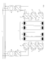
- the load 1 consists of 101 coils 10 as described above with regard to FIG. 1. Only 4 coils are represented in the figure, these being schematized only by their inductances 11, the other components of the equivalent diagram are not shown so as not to overload the figure. It can be seen in the figure that the load 1 is fed by its two opposite ends, which makes it possible to halve the supply voltage, by two sets of DC / DC converters 2, each set here comprising three cells 20, 200 mounted serial. The cells 200 are directly connected to the rectifier cells 41 while the cells 20 are not directly connected to said rectifier cells 41. The converters 2 are used as voltage variators, and as main storage elements of energy through their capacitors. continuous circuit 21.
- Each cell 20, 200 consists of a reversible chopper circuit comprising two branches 22 each comprising two elements, a diode 23 and an activatable and triggerable semiconductor element 24, for example a Gate Turn Off (GTO) or Integrated Gate Controlled Thyristor (IGCT) thyristor, as shown in the figure, or an Insulated Gate Bipolar Transistor (IGBT), mounted in H-bridge as in the figure.
- GTO Gate Turn Off
- IGCT Integrated Gate Controlled Thyristor
- IGBT Insulated Gate Bipolar Transistor
- Each cell 20, 200 comprises a storage capacitor 21 placed on the continuous side of the cell.
- the voltage transformation ratio ie the ratio between the average value of the output voltage between the terminals 25 and 26 and the input voltage between the terminals 27 and 28, ie the voltage across the capacitor 21, can be controlled for each cell 20, 200 of DC / DC converter by a modulation circuit for switching on and off the semiconductors 24 in variable durations as described below.
- FIGS. 8 and 9 Other embodiments of DC / DC converter cells 20, 200 are shown in FIGS. 8 and 9.
- inverter branches of known technology are used, according to standardized embodiments derived from FIG. industrial applications.
- the branches 22 are then constituted of so-called “two-level” inverters, as shown in FIG. 8 or "three-level", as shown in FIG. 9.
- the storage capacitor 21 associated with such a cell 20, 200 is replaced by two capacitors in series. Additional components such as switching assistance circuits, inductors, capacitors, resistors or others may be included in such circuits; they were not represented in the figures so as not to overload them.
- the DC / DC converters 20, 200 may comprise several branches 20 connected in parallel.
- the number of cells 20, 200 of DC / DC converters depends essentially on the application in question; and more particularly the level of voltage that it is necessary to achieve with respect to the maximum voltage that can withstand a capacitor.
- the CERN proton synchrotron power supply six cells 20, 200 in series are provided, divided into two groups of three as in Figure 6. Thus, for a maximum total voltage applied to the load of 9 kV as in Figure 2, this voltage is divided by six according to the number of cells 20, 200, thus giving an average voltage of the order of 1.5 kV across each cell 20, 200 respectively at the terminals of each capacitor 21 .
- the operation of the cells 20 and 200 of the DC / DC converters is carried out according to the principle of pulse duration modulation (PWM) with a frequency of pulsation (chopping frequency) generally constant.
- PWM pulse duration modulation
- chopping frequency a frequency of pulsation
- the latching and tripping control signals of the power semiconductors 24 are generated by modulators as explained below.
- FIG. 10 An embodiment of a pulse width modulator (PWM) 5, coupled to a non-DC / DC converter cell 20 directly connected to a rectifier cell 41 is shown in FIG. 10.
- PWM pulse width modulator
- the voltages U k1 to U k n measured at the terminals of all the capacitors 21 by the measuring instrument 56 are first summed and then a mean value U moy is drawn from it in the element 50. This value U av is then compared. in a comparator 51 at the voltage U k measured across the capacitor 21 corresponding to the controlled cell 20. Via a P / PI corrector 52, a duty cycle portion is added or subtracted, by a comparator 53, to a main duty cycle provided by a state regulator 54, calculating said main duty cycle from the current value to provide load and X state values measured on the load. The comparator 53 thus provides a reference voltage U cm0 . This is introduced into a divider 54 which also receives a voltage proportional to the voltage U k measured across the capacitor 21.
- the resulting signal is introduced into a discriminator 55 delivering a binary signal S k sent as a control signal of each of the triggerable and engageable semiconductors 24, respectively on the GTO thyristor gates or the bases of the IGBT transistors mounted in the DC / DC converter cell 20; .
- the capacitor 21 discharges, it is therefore possible to carry out a voltage correction by dividing U cm by a signal proportional to U d .
- Each of said DC / DC converter cells 20 is controlled by a modulator 5 as described above.
- the cells 200 of the DC / DC converters directly connected to the rectifier cells 41 are controlled by a power adjustment to ensure that said cells 200 provide the desired power, able to compensate for losses in the feeder as well as in the load.
- a proportion of the resulting signal is then added, using the adder 61, to a value P c representing an ideal power setpoint calculated from a model of the system which makes it possible to determine the loss power at each instant according to of the value of the current flowing in the magnets 10. If the losses are exactly compensated, the value U moy just before the cycle is identical to the reference value U ref and the capacitors 21 are fully loaded.
- a correction, given by the comparator 60, is introduced only if these values are different, so as to maintain the voltages of the capacitors 21 at their reference voltage.
- each can be controlled by modulators generating control signals S k which are not in phase but which are offset with each other in order to obtain an output voltage supplied to the coils 10 of which The ripple is reduced compared to an operation where all the cells would be controlled by in-phase signals.
- An example of the output voltages is shown in Figure 12. It shows the voltages U 1 , U 2 and U 3 at the terminals 25, 26 of the cells 20 and whose amplitude variation is 100% for each.
- the voltage U T which represents the sum of the voltages of the cells, ie the voltage at the terminals of the load 1 has only a variation of amplitude of 33%. At the same time, its pulse frequency has risen sharply.
- Each cell 20, 200 of DC / DC converter is connected in series to its neighbor by its output terminals 25, 26.
- each DC / DC converter cell 20, 200 between the terminals 25 and 26 depends on the value of the voltage of the capacitor 21 associated therewith.
- a control device is necessary to correct the modulation ratio of each cell 20, 200 as a function of the supply voltage of the capacitor 21.
- Figure 13 shows schematically the principle of the discharge correction of the capacitors by increasing the duty cycle of the modulator. At the beginning of the discharge, on the left side of the figure, the duty cycle is about 50%; while when the capacitor 21 is discharged, or on the right side of the figure, the same duty cycle is about 90%.
- each DC / DC converter cell 20, 200 between the terminals 25 and 26 depends on the value of the voltage of the capacitor 21 associated therewith. This voltage variation is reflected in the total voltage supplied to the coils 10 by putting the cells 20, 200 of the DC / DC converter in series.
- the charge and discharge cycles of the coils 10 described above cause losses in the various circuit components.
- energy is taken from the electrical network 4 (see FIG. 6) .
- the DC / DC converters 2 are connected to the electrical network 4 via transformers 40 and rectifier cells 41 supplying two cells 200 of DC / DC converters.
- the transformers 40 serve only to obtain an acceptable voltage level at the input of the rectifier cells 41 and to galvanically isolate the load from the network.
- the rectifier cells 41 are constituted by a diode bridge 42 as shown in FIG. 14.
- the absence of control of the diode rectifiers 42 does not make it possible to modify the voltage across the capacitors 21 of the cells 200 of the DC / DC converters.
- Such a device therefore does not make it possible to use the energy accumulated in the capacitors 21 directly connected to said cells 200 of the DC / DC converters connected to the rectifier cells 41.
- a smoothing choke 43 is provided at the positive output of the bridge.
- the variation of the output voltage of the rectifier cells 41 remains possible given the pulsation principle of the cells 200 of the DC / DC converters described above.
- the energy contribution of the capacitors 21 of the cells 200 of the DC / DC converters directly supplied by the rectifier cells 41, the two top cells 200 in the diagram of FIG. zero and the power transmitted can only be provided by the rectifier cells 41, respectively by the network.
- rectifier cells 41 similar to one of the two following embodiments will be chosen, thus allowing the set of capacitors 21 of the cells 20 of the DC / DC converters to function as storage elements.
- the rectifier cells 41 consist of a thyristor bridge 44 as shown in FIG. 15.
- the ignition angle ⁇ of the thyristors 44 will be varied as a function of the variation of the voltage across the capacitors 21. This variation in voltage thus allows the energy discharge of the capacitors 21.
- the instantaneous power provided by thyristor rectifier cells 41 is thus not equal to the instantaneous power transmitted to the load.
- a smoothing choke 43 is provided at the positive output of the cell 41.
- the rectifier cells 41 consist of pulsed rectifiers as shown in FIG. 16.
- the rectifier cell 41 comprises a bridge circuit consisting of thyristors 45 of the GTO or IGCT type, as shown in the left portion of the figure, or transistors 46, of the IGBT type, as shown in the right-hand portion of the figure, it being understood that the bridge consists solely of semiconductor elements of one or of the other type.
- Each of said above semiconductor elements 45 or 46 comprises a diode 47 mounted in antiparallel.
- the connections to the AC primary electrical network must be made via decoupling and smoothing inductors 48 as shown in the figure.
- Another advantage of such an arrangement lies in the fact that it is possible to freely impose the fundamental phase shift of the current, thus making it possible to impose a cos ⁇ , or even to operate with a unit cos ⁇ or even use these rectifier cells as reactive power compensators if necessary.
- a pulsed rectifier cell 41 as described herein imposes a lower limit of output voltage supplied to the capacitors 21, this voltage not having to become less than the the peak value of the AC input voltage of the cell 41. In the case where this DC voltage becomes lower than this peak value, only the diodes 47 remain active even in the case where the thyristors 45 or the transistors 46 are not not activated. The rectifier cell 41 would then operate as a diode rectifier, uncontrollable.
- the output of the DC side has a minimum capacitance C int , marked 49 in the figure.
- the capacitors 21 are relatively close to the cells of the pulse rectifiers 41, they can act as an output capacitance of said cells.
- a power supply device capable of delivering a relatively low value average power accompanied by power peaks provided by storage means integrated with said power supply device.
- circuits, components, semiconductor elements or cell numbers may be different as described above, depending on the type of load encountered or the current pulse to be supplied.
Abstract
Description
La présente invention concerne un dispositif d'alimentation électrique d'une charge, ledit dispositif d'alimentation comprenant un stockage d'énergie électrique intégré.The present invention relates to a device for powering a load, said power supply device comprising an integrated electrical power storage.
Certains consommateurs d'énergie électrique nécessitent d'une part la fourniture d'une puissance électrique déterminée, accompagnée d'autre part de la fourniture d'une forte énergie durant une durée relativement faible du cycle. De tels cycles peuvent être répétés. Des consommateurs de ce type sont par exemple les électro-aimants des accélérateurs de particules, les moteurs d'entraînement de laminoirs, les ascenseurs et monte-charges, les grues, etc.... Un couplage direct d'un tel consommateur au réseau électrique peut amener de graves perturbations dudit réseau. Des moyens disposés entre le réseau électrique et le consommateur sont donc généralement chargés de stocker de l'énergie afin de la délivrer au moment voulu, de manière à ce que ces pointes de consommation ne soient pas directement fournies par le réseau.Some consumers of electrical energy require on the one hand the supply of a determined electrical power, on the other hand the supply of a high energy during a relatively short period of the cycle. Such cycles can be repeated. Consumers of this type are, for example, the electromagnets of particle accelerators, the drive motors of rolling mills, the lifts and hoists, the cranes, etc. A direct coupling of such a consumer to the network electric can cause serious disturbances of said network. Means arranged between the power grid and the consumer are therefore generally responsible for storing energy in order to deliver it at the desired time, so that these consumption peaks are not directly provided by the network.
Par ailleurs, les dispositifs d'alimentation habituels en énergie sont généralement munis de dissipateurs d'énergie résistifs chargés de dissiper l'énergie lorsque le flux de puissance est inversé, ce qui évidemment gaspille beaucoup d'énergie.Furthermore, the usual power supply devices are generally provided with resistive energy dissipators charged to dissipate energy when the power flow is reversed, which obviously wastes a lot of energy.
Comme moyens de stockage d'énergie, on trouve des systèmes d'accumulation d'énergie mécanique, par exemple l'énergie cinétique d'un volant en rotation, ou d'énergie électrostatique, par exemple dans des condensateurs ou des supercondensateurs, ou d'énergie magnétique, par exemple dans des selfs, ou d'énergie électrochimique, par exemple dans des batteries d'accumulateurs.As energy storage means there are mechanical energy storage systems, for example the kinetic energy of a rotating flywheel, or electrostatic energy, for example in capacitors or supercapacitors, or magnetic energy, for example in chokes, or electrochemical energy, for example in storage batteries.
En particulier, l'article
Un but de l'invention est donc de proposer un dispositif d'alimentation électrique dans lequel un élément de stockage d'énergie est placé directement au niveau du ou des circuits intermédiaires à tension continue, sans nécessiter l'utilisation d'un convertisseur statique supplémentaire. Ceci permet premièrement d'éviter des allers et retours de flux de puissance dans un convertisseur supplémentaire, améliorant ainsi le rendement énergétique du dispositif d'alimentation, ce qui permet de limiter les coûts d'exploitation.An object of the invention is therefore to propose a power supply device in which an energy storage element is placed directly at the DC intermediate circuit (s) without requiring the use of an additional static converter. . This firstly makes it possible to avoid back and forth flow of power in an additional converter, thus improving the energy efficiency of the supply device, which makes it possible to limit operating costs.
Un autre but de l'invention est de proposer un dispositif de convertisseur statique bidirectionnel apte à alimenter un consommateur réclamant des besoins en puissance intermittente de niveau élevé et pour lesquels l'énergie nécessaire est prélevée directement du ou des circuits intermédiaires à tension continue.Another object of the invention is to provide a bi-directional static converter device capable of supplying a consumer requiring high-level intermittent power requirements and for which the energy required is taken directly from the DC intermediate circuit or circuits.
La décharge en énergie du ou des circuits intermédiaires à tension continue, circuits constitués principalement d'une association série/parallèle de condensateurs, provoque une variation du niveau de tension continue. Cette variation correspond à une diminution de tension lors du prélèvement d'énergie et à une augmentation de tension lors de la restitution d'énergie. Pour alimenter l'utilisateur, par exemple la machine d'entraînement, dans des conditions acceptables, il est nécessaire de dimensionner correctement les condensateurs du ou des circuits intermédiaires à tension continue et de corriger éventuellement la fluctuation du niveau de tension du circuit à tension continue par une modification du taux de modulation imposé au convertisseur statique disposé entre le circuit à tension continue et l'utilisateur.The energy discharge of the DC intermediate circuit (s), which circuits consist mainly of a series / parallel association of capacitors, causes a variation of the DC voltage level. This variation corresponds to a decrease in voltage during the energy sampling and to an increase in voltage during the energy recovery. To feed the user, for example the training machine, under acceptable conditions, it is it is necessary to correctly size the capacitors of the intermediate circuit (s) with DC voltage and to possibly correct the fluctuation of the voltage level of the DC voltage circuit by a modification of the modulation rate imposed on the static converter disposed between the DC voltage circuit and the DC voltage converter. user.
Particulièrement dans le contexte où l'invention est appliquée à l'alimentation du synchrotron à protons du CERN à Genève, on désire alimenter l'utilisateur, soit les bobines des aimants, à un niveau de tension élevée, de l'ordre d'une dizaine de kV. Pour ceci, l'un des buts de l'invention est de proposer un dispositif d'alimentation comprenant plusieurs convertisseurs statiques montés en série et comprenant chacun un circuit intermédiaire capacitif utilisé comme élément de stockage. Dans un tel cas, seuls quelques uns de ces convertisseurs sont alimentés à partir du réseau primaire. Les autres convertisseurs/stockeurs possèdent également un circuit intermédiaire capacitif à tension continue dont la décharge et la recharge sont liées à l'alimentation et à la récupération d'énergie des bobines des aimants.Particularly in the context in which the invention is applied to the power supply of the CERN proton synchrotron in Geneva, it is desired to supply the user, the magnet coils, with a high voltage level, of the order of one ten kV. For this, one of the aims of the invention is to propose a power supply device comprising a plurality of static converters connected in series and each comprising a capacitive intermediate circuit used as a storage element. In such a case, only a few of these converters are powered from the primary network. The other converters / storage units also have a capacitive intermediate circuit with DC voltage whose discharge and recharge are related to the power supply and the energy recovery of the coils of the magnets.
Dans une telle application, la circulation du courant dans les convertisseurs, les bobines des aimants et autres composants provoque des pertes énergétiques amenant à une décharge lente des circuits capacitifs lors de la succession des cycles d'alimentation. Afin de compenser ces décharges, un autre but de l'invention est de proposer un dispositif de commande et de réglage du fonctionnement de l'ensemble des convertisseurs permettant de transférer de l'énergie d'un convertisseur à l'autre lors de la circulation du courant délivré, permettant de maintenir les valeurs moyennes des tensions des circuits intermédiaires à tension continue par transfert énergétique d'un convertisseur à un autre, en particulier d'un convertisseur alimenté à un convertisseur non alimenté.In such an application, the flow of current in the converters, the coils of the magnets and other components causes energy losses leading to a slow discharge of the capacitive circuits during the succession of supply cycles. In order to compensate for these discharges, another object of the invention is to propose a device for controlling and adjusting the operation of all the converters making it possible to transfer energy from one converter to the other during the circulation. of the delivered current, making it possible to maintain the average values of the voltages of the intermediate DC circuits by energy transfer from one converter to another, in particular from a converter fed to a non-powered converter.
Afin d'atteindre ces buts, il est proposé un dispositif d'alimentation d'une charge, possédant les caractéristiques mentionnes dans la revendication 1, des variantes de formes d'exécution étant décrites dans les revendications dépendantes.In order to achieve these goals, it is proposed a device for feeding a load, having the characteristics mentioned in the
La description qui suit concerne une forme d'exécution de l'invention appliquée à la réalisation d'une alimentation du synchrotron à proton du CERN à Genève. Cette description n'est donnée ici qu'à titre d'exemple de réalisation de l'invention, bien d'autres applications étant également possibles. Des valeurs numériques sont indiquées uniquement à titre d'exemple se rapportant à ce consommateur d'énergie particulier. La description ci-dessous est à considérer en regard du dessin annexé comportant les figures où :
- la figure 1 représente un schéma équivalent d'un aimant de l'accélérateur,
- la figure 2 représente un diagramme du courant fourni à l'aimant de la figure précédente, respectivement au consommateur,
- la figure 3 représente un diagramme de la tension moyenne appliquée aux bornes du consommateur,
- la figure 4 représente un diagramme de la puissance instantanée demandée par le consommateur,
- la figure 5 représente un diagramme de l'énergie fournie au consommateur,
- la figure 6 représente une forme d'exécution du dispositif d'alimentation des consommateurs,
- la figure 7 représente une première forme d'exécution d'une cellule de convertisseur DC/DC,
- la figure 8 représente une autre forme d'exécution d'une cellule de convertisseur DC/DC,
- la figure 9 représente encore une autre forme d'exécution d'une cellule de convertisseur DC/DC,
- la figure 10 montre une forme d'exécution d'un modulateur de commande commandant une cellule DC/DC non directement alimentée par le réseau,
- la figure 11 montre une forme d'exécution d'un modulateur de commande commandant une cellule DC/DC directement alimentée par le réseau,
- la figure 12 est un diagramme montrant schématiquement les tensions aux bornes de trois convertisseurs DC/DC en série ainsi que la tension résultante,
- la figure 13 montre l'allure de la décroissance de la tension aux bornes d'un convertisseur DC/DC, avec une variation du rapport cyclique,
- la figure14 montre un premier exemple de forme d'exécution d'une cellule de redresseurs utilisant un montage en pont triphasé de diodes,
- la figure 15 montre un deuxième exemple de forme d'exécution d'une cellule de redresseurs utilisant un montage en pont triphasé de thyristors, et
- la figure 16 montre un troisième exemple de forme d'exécution d'une cellule de redresseurs utilisant un onduleur à pulsation,
- FIG. 1 represents an equivalent diagram of a magnet of the accelerator,
- FIG. 2 represents a diagram of the current supplied to the magnet of the preceding figure, respectively to the consumer,
- FIG. 3 represents a diagram of the average voltage applied across the consumer,
- FIG. 4 represents a diagram of the instantaneous power demanded by the consumer,
- FIG. 5 represents a diagram of the energy supplied to the consumer,
- FIG. 6 represents an embodiment of the consumer power supply device,
- FIG. 7 represents a first embodiment of a DC / DC converter cell,
- FIG. 8 represents another embodiment of a DC / DC converter cell,
- FIG. 9 represents yet another embodiment of a DC / DC converter cell,
- FIG. 10 shows an embodiment of a control modulator controlling a DC / DC cell not directly supplied by the network,
- FIG. 11 shows an embodiment of a control modulator controlling a DC / DC cell powered directly by the network,
- FIG. 12 is a diagram showing diagrammatically the voltages at the terminals of three DC / DC converters in series as well as the resulting voltage,
- FIG. 13 shows the appearance of the decrease of the voltage at the terminals of a DC / DC converter, with a variation of the duty cycle,
- FIG. 14 shows a first exemplary embodiment of a rectifier cell using a three-phase bridge arrangement of diodes,
- FIG. 15 shows a second exemplary embodiment of a rectifier cell using a three-phase bridge arrangement of thyristors, and
- FIG. 16 shows a third exemplary embodiment of a rectifier cell using a pulse inverter,
Sur la figure 1 on a représenté le schéma équivalent d'un aimant 10 d'une bobine de guidage du synchrotron à proton considéré, ladite bobine étant séparée en deux demi-bobines. L'inductance 11 de cette bobine vaut : L = 9 mH, sa résistance interne 12 vaut. R = 3.2 mΩ, sa capacité 13 par rapport au noyau magnétique vaut : C = 22 nF et sa résistance d'amortissement 14 vaut : p = 136 Ω. L'ensemble du synchrotron à proton comprend 101 bobinages tels que celui de la figure 1 montés en série.In Figure 1 there is shown the equivalent diagram of a
La figure 2 montre schématiquement un exemple de forme d'une impulsion de courant appliquée généralement au consommateur ci-dessus; l'impulsion comprend tout d'abord une montée régulière durant environ 0.65 s, suivie d'un palier à environ 6 kA durant environ 0.2 s et d'une descente régulière, ramenant le courant à zéro, durant aussi environ 0.65 s. L'impulsion est répétée toutes les 2.4 s environ.Figure 2 schematically shows an exemplary form of a current pulse generally applied to the above consumer; the pulse first comprises a steady rise for about 0.65 s, followed by a plateau at about 6 kA for about 0.2 s and a steady descent, bringing the current back to zero, also for about 0.65 s. The pulse is repeated every 2.4 seconds or so.
La forme de l'impulsion de tension appliquée aux bornes de l'ensemble des bobines du synchrotron permettant d'appliquer l'impulsion de courant mentionnée est représentée à la figure 3; partant de zéro, la tension monte brusquement à environ 9 kV pour rester stable durant toute la durée de montée en courant des bobines ; cette tension présente un deuxième palier à environ 2 kV durant le palier de courant suivi d'une séquence à tension négative allant de environ - 7.5 kV à environ - 10 kV durant la descente de courant, la tension revenant à zéro pour la fin du cycle.The form of the voltage pulse applied across the assembly of the coils of the synchrotron for applying the current pulse mentioned is shown in Figure 3; from zero, the voltage rises abruptly to about 9 kV to remain stable throughout the duration of current rise of the coils; this voltage has a second plateau at about 2 kV during the current stage followed by a negative voltage sequence ranging from about -7.5 kV to about -10 kV during the current down, the voltage going back to zero for the end of the cycle .
Des deux diagrammes précédents, on peut tirer le diagramme représenté à la figure 4 montrant la puissance instantanée PT qu'il est nécessaire de fournir au consommateur. On constate que celle-ci varie entre environ + 50 MW et - 50 MW ; de telles variations de puissance ne peuvent être acceptées par le réseau électrique. La puissance moyenne PM fournie durant le cycle est nettement plus faible, puisque de l'ordre de 5 MW ; cette courbe représente essentiellement la puissance fournie par le réseau électrique afin de compenser les pertes du système comme on le verra plus loin. La différence entre ces deux courbes, représente la puissance instantanée Pc, qui doit être fournie par le dispositif de stockage.From the two previous diagrams, it is possible to draw the diagram represented in FIG. 4 showing the instantaneous power P T that it is necessary to supply to the consumer. It can be seen that this varies between about + 50 MW and -50 MW; such power variations can not be accepted by the power grid. The average power P M supplied during the cycle is significantly lower, since of the order of 5 MW; this curve essentially represents the power supplied by the electrical network in order to compensate for the losses of the system, as will be seen below. The difference between these two curves represents the instantaneous power P c , which must be provided by the storage device.
La figure 5 montre l'allure des courbes représentant l'énergie fournie à la charge, ces courbes étant obtenues par intégration en fonction du temps des trois courbes de la figure précédente. On a donc une première courbe ET représentant l'énergie totale fournie à la charge, une deuxième courbe EM représentant l'énergie fournie par le réseau, alors que la troisième courbe Ec représente l'énergie fournie par le dispositif de stockage. On constate que celle-ci peut atteindre des valeurs de l'ordre de 20 MJ. Cette dernière énergie est fournie aux bobines essentiellement durant la durée de montée du courant, un surplus étant encore fourni durant le palier de courant afin de compenser les pertes, les bobines réalimentant ensuite le dispositif de stockage durant la décroissance du courant.FIG. 5 shows the shape of the curves representing the energy supplied to the load, these curves being obtained by integration as a function of time of the three curves of the previous figure. There is therefore a first curve E T representing the total energy supplied to the load, a second curve E M representing the energy supplied by the network, while the third curve E c represents the energy supplied by the storage device. It can be seen that this can reach values of the order of 20 MJ. This last energy is provided to coils essentially during the period of rise of the current, a surplus being still provided during the current plateau in order to compensate for the losses, the coils then feeding the storage device during the decay of the current.
Sur la figure 6 montrant un dispositif d'alimentation selon l'invention appliqué à l'alimentation du synchrotron à protons du CERN, la charge 1 est constituée de 101 bobines 10 telles que décrites plus haut en regard de la figure 1. Seules 4 bobines sont représentés sur la figure, celles-ci étant schématisées uniquement par leurs inductances 11, les autre composants du schéma équivalent n'étant pas représentés afin de ne pas surcharger la figure. On voit sur la figure que la charge 1 est alimentée par ses deux extrémités opposées, ce qui permet de diviser par deux la tension d'alimentation, par deux jeux de convertisseurs DC/DC 2, chaque jeu comprenant ici trois cellules 20, 200 montées en série. Les cellules 200 sont directement reliées aux cellules de redresseurs 41 alors que les cellules 20 ne sont pas directement reliées auxdites cellules de redresseurs 41.Les convertisseurs 2 sont utilisés comme variateurs de tension, et comme éléments de stockage principaux d'énergie de par leurs condensateurs de circuit continu 21.In FIG. 6 showing a power supply device according to the invention applied to the power supply of the CERN proton synchrotron, the
Considérant la charge 1 et les jeux de convertisseurs 2, et vu le comportement inductif de la charge 1 ainsi que le comportement capacitif des convertisseurs 2, on a échange d'énergie entre la charge 1 et les convertisseurs 2, l'énergie accumulée par la circulation du courant dans les bobines 10 étant récupérée par les condensateurs 21 des convertisseurs 2 lors de la diminution du courant dans les bobines 10 et est étant refournie auxdites bobines 10 durant la phase d'augmentation de courant, ces phases de variation de courant étant celles décrites plus haut en regard de la figure 2. Le stockage d'énergie dans les condensateurs 21 se fait selon la loi générale de fonctionnement des condensateurs E = ½ CU2. L'alimentation constituée par les convertisseurs 2, respectivement les cellules 20, 200 des convertisseurs DC/DC connectés en série permet ainsi de fournir aux bobinages 10 une tension positive servant à augmenter le courant dans les bobines 10 et une tension négative lors de la diminution du courant.Considering the
Les cellules 20 et 200 des convertisseurs DC/DC 2 sont toutes semblables, une forme d'exécution préférentielle étant représentée à la figure 7. Chaque cellule 20, 200 est constituée d'un circuit hâcheur réversible comprenant deux branches 22 comprenant chacune deux éléments, soit une diode 23 et un élément semi-conducteur enclenchable et déclenchable 24, par exemple un thyristor GTO (Gate Turn Off) ou IGCT (Integrated Gate Controlled Thyristor) comme représenté sur la figure ou un transistor IGBT (Insulated Gate Bipolar Transistor), montés en pont en H comme sur la figure. Pour des applications où le niveau de tension l'exige, on peut utiliser plusieurs éléments semi-conducteurs montés en série. Chaque cellule 20, 200 comprend un condensateur de stockage 21 placé du côté continu de la cellule. Le rapport de transformation de tension, soit le rapport entre la valeur moyenne de la tension de sortie entre les bornes 25 et 26 et la tension d'entrée entre les bornes 27 et 28, soit la tension aux bornes du condensateur 21, peut être commandé pour chaque cellule 20, 200 de convertisseur DC/DC par un circuit de modulation permettant d'enclencher et de déclencher les semi-conducteurs 24 selon des durées variables comme décrit plus bas.The
D'autres formes d'exécution de cellules 20, 200 de convertisseur DC/DC sont représentées aux figures 8 et 9. Dans ces formes d'exécution, on utilise des branches d'onduleurs de technique connue, selon des exécutions standardisées provenant d'applications industrielles. Les branches 22 sont alors constituées d'onduleurs dits « à deux niveaux », comme représenté sur la figure 8 ou « à trois niveaux », comme représenté sur la figure 9. Dans ce dernier cas, il est évident que le condensateur de stockage 21 associé à une telle cellule 20, 200 est remplacé par deux condensateurs en série. Des composants additionnels tels que circuits d'aide à la commutation, inductances, condensateurs, résistances ou autres peuvent être inclus dans de tels circuits ; ils n'ont pas été représentés sur les figures afin de ne pas les surcharger.Other embodiments of DC /
Pour une fourniture de courant élevée, les convertisseurs DC/DC 20, 200 peuvent comprendre plusieurs branches 20 montées en parallèle.For a high current supply, the DC /
Le nombre de cellules 20, 200 de convertisseurs DC/DC dépend essentiellement de l'application considérée ; et plus particulièrement du niveau de tension qu'il est nécessaire d'atteindre en regard de la tension maximum que peut supporter un condensateur. Dans le cas présent de l'alimentation du synchrotron à proton du CERN, six cellules 20, 200 en série sont prévues, réparties en deux groupes de trois comme sur la figure 6. Ainsi, pour une tension totale maximum appliquée à la charge de 9 kV comme sur la figure 2, cette tension est divisée par six selon le nombre de cellules 20, 200, donnant donc une tension moyenne de l'ordre de 1.5 kV aux bornes de chaque cellule 20, 200, respectivement aux bornes de chaque condensateur 21.The number of
Il est à noter que pour pouvoir fournir une tension moyenne de 1.5 kV indépendamment de la fluctuation de la tension continue d'entrée d'une cellule 20, 200 de convertisseur DC/DC, cette valeur devra varier entre une valeur maximale supérieure à 1.5 kV et une valeur minimale égale théoriquement à 1.5 kV. Le principe de la correction de la tension de décharge des condensateurs par augmentation du rapport cyclique est expliqué plus bas, en regard de la figure 13.It should be noted that in order to be able to supply an average voltage of 1.5 kV irrespective of the fluctuation of the DC input voltage of a DC /
Le fonctionnement des cellules 20 et 200 des convertisseurs DC/DC se fait selon le principe de la modulation en durée d'impulsions (PWM) avec une fréquence de pulsation (fréquence de hâchage) en général constante. Les signaux de commande d'enclenchement et de déclenchement des semi-conducteurs de puissance 24 sont générés par des modulateurs comme expliqué ci-dessous.The operation of the
Une forme d'exécution d'un modulateur en durée d'impulsion (PWM) 5, couplé à une cellule 20 de convertisseur DC/DC non directement reliée à une cellule de redresseur 41 est représentée à la figure 10. Le réglage en courant décrit ci-dessous permet d'assurer que les tensions aux bornes de tous les condensateurs 21 soient équilibrées en tout temps et au même niveau.An embodiment of a pulse width modulator (PWM) 5, coupled to a non-DC /
Les tensions Uk1 à Ukn mesurées aux bornes de tous les condensateurs 21 par l'instrument de mesure 56 sont tout d'abord additionnées puis une valeur moyenne Umoy en est tirée dans l'élément 50. Cette valeur Umoy est ensuite comparée, dans un comparateur 51 à la tension Uk mesurée aux bornes du condensateur 21 correspondant à la cellule 20 commandée. Via un correcteur P/PI 52, une portion de rapport cyclique est additionnée ou soustraite, par un comparateur 53, à un rapport cyclique principal fourni par un régulateur d'état 54, calculant ledit rapport cyclique principal à partir de la valeur de courant à fournir à la charge et de valeurs d'état X mesurées sur la charge. Le comparateur 53 fournit ainsi une tension de consigne Ucm0. Celle-ci est introduite dans un diviseur 54 recevant par ailleurs une tension proportionnelle à la tension Uk mesurée aux bornes du condensateur 21.The voltages U k1 to U k n measured at the terminals of all the
Le signal de sortie du diviseur vaut : Ucm = Ucm0 * k2 / k1 * Ud ce signal Ucm est ensuite comparé à un signal triangulaire Uh, à l'aide d'un soustracteur 54. Le signal résultant est introduit dans un discriminateur 55 délivrant un signal binaire Sk envoyé comme signal de commande de chacun des semi-conducteurs enclenchables et déclenchables 24, respectivement sur les gâchettes des thyristors GTO ou les bases des transistors IGBT montés dans la cellule 20 de convertisseur DC/DC. On a donc, lorsque le condensateur 21 se décharge, la possibilité d'effectuer une correction de tension en effectuant une division de Ucm par un signal proportionnel à Ud. Chacune desdites cellules 20 de convertisseur DC/DC est commandée par un modulateur 5 comme décrit ci-dessus.The output signal of the divider is: U cm = U cm0 * k 2 / k 1 * U d this signal U cm is then compared to a triangular signal U h , using a
Comme représenté à la figure 11, les cellules 200 des convertisseurs DC/DC directement reliées aux cellules de redresseurs 41 sont commandées par un réglage de puissance permettant d'assurer que lesdites cellules 200 fournissent la puissance voulue, apte à compenser les pertes dans le dispositif d'alimentation ainsi que dans la charge.As shown in FIG. 11, the
La valeur moyenne U moy des tensions des condensateurs 21 juste avant le cycle, mesurée par l'instrument de mesure 56 est comparée dans le comparateur 60 à une valeur de référence Uref. Une proportion du signal résultant est ensuite ajoutée, à l'aide du sommateur 61, à une valeur Pc représentant une consigne de puissance idéale calculée à partir d'un modèle du système qui permet de déterminer la puissance de perte à chaque instant en fonction de la valeur du courant circulant dans les aimants 10. Si les pertes sont exactement compensées, la valeur Umoy juste avant le cycle est identique à la valeur de référence Uref et les condensateurs 21 sont pleinement chargés. Une correction, donnée par le comparateur 60, n'est introduite que si ces valeurs sont différentes, de manière à conserver les tensions des condensateurs 21 à leur tension de référence. Le signal de correction fourni par le comparateur 61 et comparé à la puissance mesurée Pmes dans un comparateur 62, le signal résultant de ce dernier comparateur permettant de régler la tension aux bornes du condensateur 21 de la même manière que décrite plus haut et par des éléments comparables à ceux décrits en regard de la figure 10.The average value U moy of the voltages of the
Vu le montage en série des cellules 20, chacune peut être commandée par des modulateurs générant des signaux de commande Sk qui ne sont pas en phase mais qui sont décalés entre eux afin d'obtenir une tension de sortie fournie aux bobines 10 dont l'ondulation est réduite par rapport à un fonctionnement où toutes les cellules 20 seraient commandées par des signaux en phase. Un exemple des tensions de sorties est montré à la figure 12. On y voit les tensions U1, U2 et U3 aux bornes 25, 26 des cellules 20 et dont la variation d'amplitude est de 100% pour chacune. La tension UT qui représente la somme des tensions des cellules, soit la tension aux bornes de la charge 1 n'a plus qu'une variation d'amplitude de 33 %. Simultanément sa fréquence de pulsation a fortement augmenté.In view of the series connection of the
Chaque cellule 20, 200 de convertisseur DC/DC est reliée en série à sa voisine par ses bornes de sortie 25, 26.Each
Lors de la phase d'alimentation des bobines 10, soit durant la phase de montée du courant, l'énergie est transmise depuis les condensateurs 21, entraînant leur décharge. Il s'ensuit que la tension de sortie de chaque cellule 20, 200 de convertisseur DC/DC entre les bornes 25 et 26 dépend de la valeur de la tension du condensateur 21 qui lui est associé.During the supply phase of the
Afin de pouvoir alimenter la charge 1 avec une tension imposée, indépendamment de la fluctuation des tensions des condensateurs 21, un dispositif de commande est nécessaire pour corriger le taux de modulation de chaque cellule 20, 200 en fonction de la tension d'alimentation du condensateur 21.In order to be able to supply the
La valeur moyenne Vmoy de la tension de sortie d'une cellule 20, 200 est donnée par : ![]()
- Avec: t1 =
- durée de l'impulsion
- Tp =
- période de répétition des impulsions
- Ud =
- tension aux bornes du condensateur
- With: t 1 =
- duration of the impulse
- T p =
- pulse repetition period
- U d =
- voltage across the capacitor
La figure 13 montre schématiquement le principe de la correction de décharge des condensateurs par augmentation du rapport cyclique du modulateur. Au début de la décharge, soit sur la partie gauche de la figure, le rapport cyclique est d'environ 50% ; alors que lorsque le condensateur 21 est déchargé, soit sur la partie droite de la figure, le même rapport cyclique vaut environ 90 %.Figure 13 shows schematically the principle of the discharge correction of the capacitors by increasing the duty cycle of the modulator. At the beginning of the discharge, on the left side of the figure, the duty cycle is about 50%; while when the
Lors de la phase de décharge des bobines 10, soit durant la phase de descente du courant, l'énergie est transmise aux condensateurs 21, entraînant leur recharge. Il s'ensuit que la tension de sortie de chaque cellule 20, 200 de convertisseur DC/DC entre les bornes 25 et 26 dépend de la valeur de la tension du condensateur 21 qui lui est associé. Cette variation de tension se répercute sur la tension totale fournie aux bobines 10 par la mise en série des cellules 20, 200 de convertisseur DC/DC.During the discharge phase of the
Les cycles de charge et décharge des bobines 10 décrits ci-dessus entraînent des pertes dans les divers composants de circuits. Afin de compenser ces pertes, de l'énergie est prélevée du réseau électrique 4 (voir figure 6).Pour ceci, les convertisseurs DC/DC 2 sont reliés au réseau électrique 4 par l'intermédiaire de transformateurs 40 et de cellules de redresseurs 41, alimentant deux cellules 200 de convertisseurs DC/DC. Les transformateurs 40 servent uniquement à obtenir un niveau de tension acceptable à l'entrée des cellules de redresseurs 41 et à isoler galvaniquement la charge du réseau.The charge and discharge cycles of the
Selon une première forme d'exécution, les cellules de redresseurs 41 sont constituées par un pont de diodes 42 comme représenté à la figure 14. Dans cette forme d'exécution, l'absence de contrôle des redresseurs à diodes 42 ne permet pas de modifier la tension aux bornes des condensateurs 21 des cellules 200 des convertisseurs DC/DC. Un tel dispositif ne permet donc pas d'utiliser l'énergie accumulée dans les condensateurs 21 directement reliées auxdites cellules 200 des convertisseurs DC/DC reliées aux cellules de redresseurs 41. Une self de lissage 43 est prévue à la sortie positive du pont.According to a first embodiment, the
La variation de la tension de sortie des cellules de redresseurs 41 reste possible vu le principe de pulsation des cellules 200 des convertisseurs DC/DC décrit plus haut. Lors de l'augmentation du courant dans la charge, la contribution énergétique des condensateurs 21 des cellules 200 des convertisseurs DC/DC directement alimentés par les cellules de redresseurs 41, les deux cellules 200 du haut dans le schéma de la figure 6, est donc nulle et la puissance transmise ne peut donc être fournie que par les cellules de redresseurs 41, respectivement par le réseau. Dans ce cas, seuls les condensateurs 21 des cellules 20 des convertisseurs DC/DC non directement connectées à des cellules de redresseurs 41, les quatre cellules du bas dans le schéma de la figure 6, fonctionnent en éléments de stockage.The variation of the output voltage of the
De manière préférentielle on choisira des cellules de redresseur 41 semblables à l'une des deux formes d'exécution suivantes, permettant ainsi que l'ensembles des condensateurs 21 des cellules 20 des convertisseurs DC/DC fonctionnent en éléments de stockage.Preferably,
Selon une deuxième forme d'exécution, les cellules de redresseurs 41 sont constituées par un pont de thyristors 44 comme représenté à la figure 15. Avec cette forme d'exécution, il devient alors possible de faire varier la tension aux bornes des condensateurs 21. Pour la commande des ponts de thyristors on fera varier l'angle d'allumage α des thyristors 44 en fonction de la variation de la tension aux bornes des condensateurs 21. Cette variation de tension permet donc la décharge énergétique des condensateurs 21. La puissance instantanée fournie par les cellules de redresseurs 41 à thyristors n'est donc ainsi pas égale à la puissance instantanée transmise à la charge. Comme pour la forme d'exécution précédente, une self de lissage 43 est prévue à la sortie positive de la cellule 41.According to a second embodiment, the
L'utilisation de thyristors dans les cellules de redresseurs 41, avec une commande de l'angle d'allumage α desdits thyristors 44, implique une variation de l'angle de déphasage entre la tension et le courant alternatif à l'entrée des cellules de redresseurs 41 , entraînant ainsi une consommation de puissance réactive au réseau primaire. Ces phénomènes sont décrits et expliqués dans : « H. Bühler - Electronique de puissance - Traité d'Electricité - vol XV - PPUR , Presses Polytechniques et Universitaires Romandes - Chap. 9, para 9.2.4 et 9.4.1 »The use of thyristors in the
Afin de limiter la puissance réactive prélevée, on peut utiliser une commande à séquence telle que décrite au chap 9.5 du manuel mentionné ci-dessus.In order to limit the reactive power taken, a sequential control can be used as described in chapter 9.5 of the manual mentioned above.
Selon une troisième forme d'exécution, les cellules de redresseurs 41 sont constituées de redresseurs à pulsations comme représenté à la figure 16. Dans ce cas, la cellule de redresseurs 41 comprend un montage en pont constitué de thyristors 45 de type GTO ou IGCT, comme représenté sur la portion de gauche de la figure, ou de transistors 46, de type IGBT, comme représenté sur la portion de droite de la figure, étant entendu que le pont est uniquement constitué d'éléments semi-conducteurs de l'un ou de l'autre type. Chacun desdits éléments semi-conducteurs ci-dessus 45 ou 46 comprend une diode 47 montée en anti-parallèle. Dans le cas d'utilisation d'une cellule de redresseur 41 à pulsation, les liaisons avec le réseau électrique primaire alternatif doivent se faire par l'intermédiaire d'inductances de découplage et de lissage 48 comme représenté sur la figure.According to a third embodiment, the
Avec un tel montage, on trouve un premier avantage dans la forme du courant alternatif primaire dont la forme est très proche d'une forme sinusoïdale et dont les harmoniques sont liées à la fréquence de pulsation. Contrairement à la forme des courants alternatifs des redresseurs à diodes ou thyristors décrits plus haut, les courant alternatifs des redresseurs 41 à pulsations sont exempts d'harmoniques à basses fréquences (γ = 5, 7, 11, ... ).With such an arrangement, there is a first advantage in the form of the primary alternating current whose shape is very close to a sinusoidal form and whose harmonics are related to the frequency of pulsation. Unlike the shape of the alternating currents of the rectifiers with diodes or thyristors described above, the alternating currents of the
Un autre avantage d'un tel montage réside dans le fait qu'il est possible d'imposer librement le déphasage d'onde fondamentale du courant, permettant ainsi d'imposer un cos ϕ, voire de fonctionner avec un cos ϕ unitaire ou même d'utiliser ces cellules de redresseurs comme compensateurs de puissance réactive si nécessaire.Another advantage of such an arrangement lies in the fact that it is possible to freely impose the fundamental phase shift of the current, thus making it possible to impose a cos φ, or even to operate with a unit cos φ or even use these rectifier cells as reactive power compensators if necessary.
Une cellule de redresseurs 41 à pulsations telle que décrite ici impose une limite inférieure de tension de sortie fournie aux condensateurs 21, cette tension ne devant pas devenir inférieure à la valeur de crête de la tension alternative d'entrée de la cellule 41. Dans le cas où cette tension continue deviendrait inférieure à cette valeur de crête seules les diodes 47 resteraient actives, même dans le cas où les thyristors 45 ou les transistors 46 ne seraient pas activés. La cellule de redresseurs 41 fonctionnerait alors comme un redresseur à diodes, non contrôlable.A
Au dessus de cette valeur limite inférieure, il est possible de faire varier la tension aux bornes des condensateurs 21, permettant ainsi d'exploiter leur capacité de stockage d'énergie, respectivement leur capacité d'emmagasiner et de restituer de l'énergie.Above this lower limit value, it is possible to vary the voltage across the
Pour un fonctionnement correct du redresseur à pulsations, il est nécessaire que la sortie du côté DC présente une capacité minimum Cint, repérée par 49 sur la figure. Pour le cas où les condensateurs 21 sont relativement proches des cellules des redresseurs à pulsations 41, ils peuvent faire office de capacité de sortie desdites cellules.For correct operation of the pulse rectifier, it is necessary that the output of the DC side has a minimum capacitance C int , marked 49 in the figure. For the case where the
Il est évident que la description ci-dessus d'un dispositif d'alimentation est donnée à titre d'exemple d'une forme d'exécution possible d'un dispositif d'alimentation apte à délivrer une puissance moyenne de relativement faible valeur accompagnée de pointes de puissances fournies par des moyens de stockage intégrés audit dispositif d'alimentation. En particulier des dispositions de circuits, de composants, des éléments semi-conducteurs ou des nombres de cellules peuvent être différents que décrit ci-dessus, selon le type de charge rencontrée ou d'impulsion de courant à fournir.It is obvious that the above description of a power supply device is given by way of example of a possible embodiment of a power supply device capable of delivering a relatively low value average power accompanied by power peaks provided by storage means integrated with said power supply device. In particular arrangements of circuits, components, semiconductor elements or cell numbers may be different as described above, depending on the type of load encountered or the current pulse to be supplied.
Claims (11)
caractérisé en ce qu'il comprend en outre
une pluralité de convertisseurs DC/DC (2) montés en série aux bornes de la charge, un au moins desdits convertisseurs DC/DC (200) étant alimenté par le moyen de redressement de tension, un condensateur de stockage (21) étant monté en parallèle sur chacun desdits convertisseurs DC/DC (20, 200).Device for supplying a load (1) requiring, on the one hand, the provision of a determined electrical power and, on the other hand, the provision of a high energy during a short duration of the operating cycle, the operating cycle being repeated, said power supply device comprising a connection to an electrical network (4), AC voltage transformation means (40), voltage rectifying means (41),
characterized in that it further comprises
a plurality of DC / DC converters (2) connected in series across the load, at least one of said DC / DC converters (200) being powered by the voltage rectifying means, a storage capacitor (21) being mounted in parallel on each of said DC / DC converters (20, 200).
Priority Applications (8)
| Application Number | Priority Date | Filing Date | Title |
|---|---|---|---|
| EP06012385A EP1868279A1 (en) | 2006-06-16 | 2006-06-16 | Device for supplying a load with an integrated energy storage |
| PCT/CH2007/000284 WO2007143868A1 (en) | 2006-06-16 | 2007-06-07 | Device for feeding a charge including integrated energy storage |
| JP2009514607A JP5095731B2 (en) | 2006-06-16 | 2007-06-07 | Load power supply device with built-in energy storage device |
| EP07720181A EP2033295B1 (en) | 2006-06-16 | 2007-06-07 | Device for feeding a charge including integrated energy storage |
| CA2655023A CA2655023C (en) | 2006-06-16 | 2007-06-07 | Load power supply device comprising integrated energy storage |
| DE602007005131T DE602007005131D1 (en) | 2006-06-16 | 2007-06-07 | DEVICE FOR FEEDING A CHARGE, INCLUDING INTEGRATED ENERGY STORAGE |
| AT07720181T ATE460002T1 (en) | 2006-06-16 | 2007-06-07 | DEVICE FOR INJECTION OF A CHARGE, INCLUDING INTEGRATED ENERGY STORAGE |
| US12/314,775 US8723365B2 (en) | 2006-06-16 | 2008-12-16 | Device for feeding a charge including integrated energy storage |
Applications Claiming Priority (1)
| Application Number | Priority Date | Filing Date | Title |
|---|---|---|---|
| EP06012385A EP1868279A1 (en) | 2006-06-16 | 2006-06-16 | Device for supplying a load with an integrated energy storage |
Publications (1)
| Publication Number | Publication Date |
|---|---|
| EP1868279A1 true EP1868279A1 (en) | 2007-12-19 |
Family
ID=37434112
Family Applications (2)
| Application Number | Title | Priority Date | Filing Date |
|---|---|---|---|
| EP06012385A Withdrawn EP1868279A1 (en) | 2006-06-16 | 2006-06-16 | Device for supplying a load with an integrated energy storage |
| EP07720181A Not-in-force EP2033295B1 (en) | 2006-06-16 | 2007-06-07 | Device for feeding a charge including integrated energy storage |
Family Applications After (1)
| Application Number | Title | Priority Date | Filing Date |
|---|---|---|---|
| EP07720181A Not-in-force EP2033295B1 (en) | 2006-06-16 | 2007-06-07 | Device for feeding a charge including integrated energy storage |
Country Status (6)
| Country | Link |
|---|---|
| EP (2) | EP1868279A1 (en) |
| JP (1) | JP5095731B2 (en) |
| AT (1) | ATE460002T1 (en) |
| CA (1) | CA2655023C (en) |
| DE (1) | DE602007005131D1 (en) |
| WO (1) | WO2007143868A1 (en) |
Cited By (5)
| Publication number | Priority date | Publication date | Assignee | Title |
|---|---|---|---|---|
| EP2293422A1 (en) | 2009-09-04 | 2011-03-09 | Converteam Technology Ltd | Converter of one direct current to another direct current with control signal interleaving, and power supply system including such a converter |
| WO2011117537A1 (en) | 2010-03-23 | 2011-09-29 | Converteam Technology Ltd. | Method and device for predetermining value for characteristic quantity from load-supplying system |
| FR2958093A1 (en) * | 2010-03-23 | 2011-09-30 | Converteam Technology Ltd | METHOD AND DEVICE FOR DRIVING THE VOLTAGE AT THE TERMINALS OF A CLEAN CHARGE TO BE POWERED BY A POWER SUPPLY SYSTEM |
| EP2437386A1 (en) * | 2010-10-04 | 2012-04-04 | PL Technologies AG | Stabilized high-voltage power supply |
| EP2963761A1 (en) * | 2014-07-02 | 2016-01-06 | Haldor Topsøe A/S | An efficient AC-DC electrical power converting unit configuration |
Families Citing this family (2)
| Publication number | Priority date | Publication date | Assignee | Title |
|---|---|---|---|---|
| US8723365B2 (en) | 2006-06-16 | 2014-05-13 | Ecole Polytechnique Federale De Lausanne (Epfl) | Device for feeding a charge including integrated energy storage |
| EP2234263A1 (en) | 2009-03-27 | 2010-09-29 | Koninklijke Philips Electronics N.V. | A power supply, method, and computer program product for supplying electrical power to a load |
Citations (2)
| Publication number | Priority date | Publication date | Assignee | Title |
|---|---|---|---|---|
| US5638263A (en) * | 1994-03-01 | 1997-06-10 | Halmar Robicon Group | Low and medium voltage PWM AC/DC power conversion method and apparatus |
| US20030214824A1 (en) * | 2000-08-16 | 2003-11-20 | Corzine Keith Allen | Cascaded multi-level h-bridge drive |
Family Cites Families (4)
| Publication number | Priority date | Publication date | Assignee | Title |
|---|---|---|---|---|
| US5694307A (en) * | 1996-09-30 | 1997-12-02 | Alliedsignal Inc. | Integrated AC/DC and DC/DC converter |
| WO2001024591A1 (en) * | 1999-09-27 | 2001-04-05 | Hitachi, Ltd. | Apparatus for charged-particle beam irradiation, and method of control thereof |
| US6751109B2 (en) * | 2001-10-31 | 2004-06-15 | Mobility Electronics, Inc. | Dual input AC/DC/ battery operated power supply |
| US20050157525A1 (en) * | 2004-01-20 | 2005-07-21 | Hanson George E. | Dual AC and DC input DC power supply |
-
2006
- 2006-06-16 EP EP06012385A patent/EP1868279A1/en not_active Withdrawn
-
2007
- 2007-06-07 CA CA2655023A patent/CA2655023C/en not_active Expired - Fee Related
- 2007-06-07 JP JP2009514607A patent/JP5095731B2/en not_active Expired - Fee Related
- 2007-06-07 EP EP07720181A patent/EP2033295B1/en not_active Not-in-force
- 2007-06-07 WO PCT/CH2007/000284 patent/WO2007143868A1/en active Application Filing
- 2007-06-07 DE DE602007005131T patent/DE602007005131D1/en active Active
- 2007-06-07 AT AT07720181T patent/ATE460002T1/en not_active IP Right Cessation
Patent Citations (2)
| Publication number | Priority date | Publication date | Assignee | Title |
|---|---|---|---|---|
| US5638263A (en) * | 1994-03-01 | 1997-06-10 | Halmar Robicon Group | Low and medium voltage PWM AC/DC power conversion method and apparatus |
| US20030214824A1 (en) * | 2000-08-16 | 2003-11-20 | Corzine Keith Allen | Cascaded multi-level h-bridge drive |
Non-Patent Citations (4)
| Title |
|---|
| ALFRED RUFER ET AL: "A Supercapacitor-Based Energy-Storage System for Elevators With Soft Commutated Interface", IEEE TRANSACTIONS ON INDUSTRY APPLICATIONS, IEEE SERVICE CENTER, PISCATAWAY, NJ, US, vol. 38, no. 5, September 2002 (2002-09-01), XP011073540, ISSN: 0093-9994 * |
| BARRADE, PITTET, RUFER: "Energy Storage System using a series connection of supercapacitors, with an active device for equalising the voltages", INTERNATIONAL POWER ELECTRONICS CONFERENCE, 2000, Tokyo, Japan, XP002410954 * |
| NOWAK M ET AL: "Converters with AC transformer intermediate link suitable as interfaces for supercapacitor energy storage", POWER ELECTRONICS SPECIALISTS CONFERENCE, 2004. PESC 04. 2004 IEEE 35TH ANNUAL AACHEN, GERMANY 20-25 JUNE 2004, PISCATAWAY, NJ, USA,IEEE, US, 20 June 2004 (2004-06-20), pages 4067 - 4073Vol5, XP010738362, ISBN: 0-7803-8399-0 * |
| RUFER A ET AL: "A supercapacitor-based energy storage system for elevators with soft commutated interface", CONFERENCE RECORD OF THE 2001 IEEE INDUSTRY APPLICATIONS CONFERENCE. 36TH IAS ANNUAL MEETING . CHICAGO, IL, SEPT. 30 - OCT. 4, 2001, CONFERENCE RECORD OF THE IEEE INDUSTRY APPLICATIONS CONFERENCE. IAS ANNUAL MEETING, NEW YORK, NY : IEEE, US, vol. VOL. 1 OF 4. CONF. 36, 30 September 2001 (2001-09-30), pages 1413 - 1418, XP010561878, ISBN: 0-7803-7114-3 * |
Cited By (11)
| Publication number | Priority date | Publication date | Assignee | Title |
|---|---|---|---|---|
| EP2293422A1 (en) | 2009-09-04 | 2011-03-09 | Converteam Technology Ltd | Converter of one direct current to another direct current with control signal interleaving, and power supply system including such a converter |
| FR2949920A1 (en) * | 2009-09-04 | 2011-03-11 | Converteam Technology Ltd | CONVERTER OF CONTINUOUS CURRENT IN ANOTHER CURRENT CURRENT WITH CONTROL SIGNAL NAMES, AND POWER SUPPLY SYSTEM COMPRISING SUCH CONVERTER |
| WO2011117537A1 (en) | 2010-03-23 | 2011-09-29 | Converteam Technology Ltd. | Method and device for predetermining value for characteristic quantity from load-supplying system |
| FR2958046A1 (en) * | 2010-03-23 | 2011-09-30 | Converteam Technology Ltd | METHOD AND DEVICE FOR DETERMINING THE VALUE OF A CHARACTERISTIC SIZE OF A CHARGE POWER SYSTEM |
| FR2958093A1 (en) * | 2010-03-23 | 2011-09-30 | Converteam Technology Ltd | METHOD AND DEVICE FOR DRIVING THE VOLTAGE AT THE TERMINALS OF A CLEAN CHARGE TO BE POWERED BY A POWER SUPPLY SYSTEM |
| EP2378651A2 (en) | 2010-03-23 | 2011-10-19 | Converteam Technology Ltd | Method and device for controlling the voltage at the terminals of a charge suitable for being supplied by a supply system |
| US9054574B2 (en) | 2010-03-23 | 2015-06-09 | Ge Energy Power Conversion Technology Ltd. | Method and device for determining the value of a characteristic quantity of a system for powering a load |
| EP2378651A3 (en) * | 2010-03-23 | 2017-01-11 | GE Energy Power Conversion Technology Limited | Method and device for controlling the voltage at the terminals of a charge suitable for being supplied by a supply system |
| EP2437386A1 (en) * | 2010-10-04 | 2012-04-04 | PL Technologies AG | Stabilized high-voltage power supply |
| EP2963761A1 (en) * | 2014-07-02 | 2016-01-06 | Haldor Topsøe A/S | An efficient AC-DC electrical power converting unit configuration |
| WO2016000957A1 (en) * | 2014-07-02 | 2016-01-07 | Haldor Topsøe A/S | An efficient ac-dc electrical power converting unit configuration |
Also Published As
| Publication number | Publication date |
|---|---|
| WO2007143868A8 (en) | 2008-12-31 |
| JP5095731B2 (en) | 2012-12-12 |
| EP2033295B1 (en) | 2010-03-03 |
| JP2009540786A (en) | 2009-11-19 |
| DE602007005131D1 (en) | 2010-04-15 |
| CA2655023C (en) | 2017-02-28 |
| CA2655023A1 (en) | 2007-12-21 |
| WO2007143868A1 (en) | 2007-12-21 |
| ATE460002T1 (en) | 2010-03-15 |
| EP2033295A1 (en) | 2009-03-11 |
Similar Documents
| Publication | Publication Date | Title |
|---|---|---|
| EP2033295B1 (en) | Device for feeding a charge including integrated energy storage | |
| Bharatee et al. | A power management scheme for grid-connected PV integrated with hybrid energy storage system | |
| US8723365B2 (en) | Device for feeding a charge including integrated energy storage | |
| Krishnamoorthy et al. | Wind turbine generator–battery energy storage utility interface converter topology with medium-frequency transformer link | |
| EP3075058B1 (en) | Device for balancing a power battery element load | |
| EP2020726A2 (en) | Method of powering emergency auxiliary loads, auxiliary converter and railway vehicle for this method | |
| FR3004870A1 (en) | METHOD AND DEVICE FOR CONTROLLING A RESONANCE CONTINUOUS CURRENT-CURRENT MULTI-PHASE CONVERTER, AND CORRESPONDING MULTIPHASE CONVERTER | |
| EP2641323B1 (en) | Variable-speed drive provided with a supercapacitor module | |
| WO2009062227A1 (en) | Electrical energy and distribution system | |
| EP2338225B1 (en) | Energy recovery device in a variable-frequency drive | |
| EP2289161A1 (en) | High power rectifier circuit particularly for aluminium electrolysis | |
| EP2281337B1 (en) | Method for recovering power in a variable speed drive | |
| FR2999033A1 (en) | PHOTOVOLTAIC SYSTEM AND METHOD FOR MANAGING IT | |
| EP2452423A1 (en) | Novel architecture of a compensator for power factors and harmonics for a power distribution network | |
| EP1564876B1 (en) | Welding unit with soft switching quasi-resonant inverter | |
| FR2999357A1 (en) | ELECTRIC DRIVE CHAIN OF A DEVICE, AND GAS COMPRESSION EQUIPMENT COMPRISING SUCH A CHAIN | |
| EP2562903B1 (en) | Reactive power compensator comprising N inverters in parallel, N banks of capacitor(s) and a means for connecting the banks via passive electrical components | |
| EP3539204B1 (en) | Method for controlling a three-phase rectifier for a charging device on board an electric or hybrid vehicle | |
| FR3038796A1 (en) | ENERGY GENERATING SYSTEM WITH IMPROVED TREATMENT OF LOAD IMPACTS, DELAYS AND HARMONICS | |
| FR2987512A1 (en) | CHARGING CIRCUIT OF AN ENERGY SUPPLYING PLANT AND METHOD OF APPLICATION THEREOF | |
| JP5528730B2 (en) | Power converter | |
| WO2010004190A1 (en) | Arc welding set with an optimized quasi-resonant soft-switching inverter | |
| Ali et al. | Application Of Renewable Energy Sources For Effective Energy Management | |
| FR3089361A1 (en) | Alternating arm converter current source, power conversion system and method for controlling such a converter | |
| D’arco et al. | Energy management of stand-alone power systems with renewable energy sources. |
Legal Events
| Date | Code | Title | Description |
|---|---|---|---|
| PUAI | Public reference made under article 153(3) epc to a published international application that has entered the european phase |
Free format text: ORIGINAL CODE: 0009012 |
|
| AK | Designated contracting states |
Kind code of ref document: A1 Designated state(s): AT BE BG CH CY CZ DE DK EE ES FI FR GB GR HU IE IS IT LI LT LU LV MC NL PL PT RO SE SI SK TR |
|
| AX | Request for extension of the european patent |
Extension state: AL BA HR MK YU |
|
| AKX | Designation fees paid | ||
| REG | Reference to a national code |
Ref country code: DE Ref legal event code: 8566 |
|
| STAA | Information on the status of an ep patent application or granted ep patent |
Free format text: STATUS: THE APPLICATION IS DEEMED TO BE WITHDRAWN |
|
| 18D | Application deemed to be withdrawn |
Effective date: 20080620 |