EP1598924A2 - Inverter without harmonics - Google Patents
Inverter without harmonics Download PDFInfo
- Publication number
- EP1598924A2 EP1598924A2 EP05106885A EP05106885A EP1598924A2 EP 1598924 A2 EP1598924 A2 EP 1598924A2 EP 05106885 A EP05106885 A EP 05106885A EP 05106885 A EP05106885 A EP 05106885A EP 1598924 A2 EP1598924 A2 EP 1598924A2
- Authority
- EP
- European Patent Office
- Prior art keywords
- inverter
- output
- harmonics
- choke
- current
- Prior art date
- Legal status (The legal status is an assumption and is not a legal conclusion. Google has not performed a legal analysis and makes no representation as to the accuracy of the status listed.)
- Granted
Links
Images

Classifications
-
- H—ELECTRICITY
- H02—GENERATION; CONVERSION OR DISTRIBUTION OF ELECTRIC POWER
- H02M—APPARATUS FOR CONVERSION BETWEEN AC AND AC, BETWEEN AC AND DC, OR BETWEEN DC AND DC, AND FOR USE WITH MAINS OR SIMILAR POWER SUPPLY SYSTEMS; CONVERSION OF DC OR AC INPUT POWER INTO SURGE OUTPUT POWER; CONTROL OR REGULATION THEREOF
- H02M1/00—Details of apparatus for conversion
- H02M1/12—Arrangements for reducing harmonics from ac input or output
- H02M1/126—Arrangements for reducing harmonics from ac input or output using passive filters
-
- H—ELECTRICITY
- H02—GENERATION; CONVERSION OR DISTRIBUTION OF ELECTRIC POWER
- H02M—APPARATUS FOR CONVERSION BETWEEN AC AND AC, BETWEEN AC AND DC, OR BETWEEN DC AND DC, AND FOR USE WITH MAINS OR SIMILAR POWER SUPPLY SYSTEMS; CONVERSION OF DC OR AC INPUT POWER INTO SURGE OUTPUT POWER; CONTROL OR REGULATION THEREOF
- H02M1/00—Details of apparatus for conversion
- H02M1/12—Arrangements for reducing harmonics from ac input or output
- H02M1/123—Suppression of common mode voltage or current
Definitions
- the invention relates to an inverter or an output filter for inverters.
- the output current of an inverter for higher power points in usually a whole bunch of current harmonics up. These harmonics are annoying and especially if greater power over inverter be fed into a network, they occur unpleasantly.
- FIG. 1 shows an inverter with an output choke and a capacitor filter network shown, the above-described technical disadvantage of inverters significantly reduced and the power quality significantly improved.
- the power switches T1 to T6 and the diodes connected in parallel therewith be switched by means of a pulse width modulation of the circuit breaker, that at the output of the inverter three sinusoidal output currents phases U, V, W arise.
- the shape of the output current is determined by Switching the individual switches T1-T6 on or off approximates to a sinusoidal oscillation. However, due to the inevitable deviations from the Setpoint the mentioned harmonics.
- FIG. 1 shows the circuit diagram of a known inverter, which by the Anti-parallel connection of the power switches T1 to T6, each with a diode D1-D6 allows a four-quadrant operation and thus very versatile as a circuit can be used.
- Tn 1, 3, 5
- the circuit breakers is a DC voltage intermediate circuit with two series-connected electrolytic capacitors C4 and C5 for feeding the DC voltage + Ud and - Ud upstream.
- the inverter points an output choke LA (LAU, LAV, LAW) and a downstream Filter consisting of three capacitors C6, C7, C8, which between each Phases are arranged on.
- LA LAU, LAV, LAW
- C6, C7, C8 which between each Phases are arranged on.
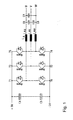
- FIG. 2 shows the circuit diagram of an inverter according to the invention. This has as the known inverter DC voltage intermediate circuit breaker T1 - T6 and parallel connected diodes D1 - D6 and a Output choke LA on.
- the inverter according to the invention generates unbalanced harmonics.
- an additional winding L4 (additional leg) is provided. 1
- This fourth leg L4 transmits the unbalanced magnetic fluxes that out the unbalanced harmonics arise.
- the harmonics will be over three oscillating circuits LC or three L-C-links, consisting of the inductivities L1 to L3 and the capacitors C1 to C3 and a common Star point. Symmetric harmonics are with these resonant circuits LC, as far as they are still available, directly compensated.
- Unbalanced harmonics L4 ( ⁇ I ⁇ 0) will be over the neutral point of the winding of the fourth Supplied to Schenkel's L4.
- This fourth winding L4 is connected to the minus rail of the DC DC link connected.
- the sum of the unbalanced ones Harmonics is thus tapped at the star point of the filter capacitors and via the winding on the fourth leg L4 in the DC intermediate circuit coupled. This results in a closed harmonic current circuit for the unbalanced harmonics.
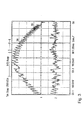
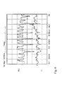
- FIG. 3 shows a measuring diagram of the inverter according to FIG. 2.
- the upper curve shows the positive sine half-wave of the current at the inverter output. In this case, the hysteresis of the current is constant and the switching frequency variable.
- the lower curve shows the sum of the harmonics of the three Output phases of the inverter, which over the fourth leg in the Return DC voltage intermediate circuit.
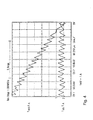
- Figure 4 shows again a part of the output current of the inverter of Phase 1 in higher resolution. Here are clearly the triangular harmonics of the output current IWR LA.
- Figure 5 shows the result of the separation of the harmonics from the main stream (Fundamental 50 Hz).
- the uppermost curve shows the output current without harmonics. This very good result is only with the invention Harmonic circuit possible.
- the middle curve in FIG. 5 shows the inverter current IWR LA and the lower curve in Figure 5 shows again the associated harmonic current.
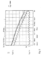
- FIG. 6 shows the sum of the three harmonic currents I21, I22 and I23.
- This current which contains almost all the harmonics of the three phases, is now used again to increase the effect of the output inductor LA.
- This throttle consists, as already described, of the three main legs LA1, LA2, LA3 for the three main output windings and a fourth small daughter leg, which is intended only for the harmonics.
- This fourth Thigh leads only the magnetic fluxes, which is the sum of the harmonics correspond.
- the corresponding amplitude of this summation current of the harmonics is shown in Figure 6, lower curve.
- the upper curve shows the corresponding voltage curve for this purpose. To achieve this is an iron cross section of about 20% of the main leg sufficient for the fourth leg. Of the fourth leg increases but the acting output inductance LA by about 5-20%. This results in a smaller size of the output inductor LA and a better one Efficiency.
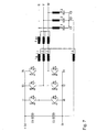
- FIG. 7 shows a development of the inverter according to the invention.
- the Output choke is in this case constructed in two parts and consists of a four-limb throttle and a series-connected compensated three-phase reactor LA2.
- For unbalanced harmonic currents can be advantageous current-compensated Chokes are used. Since the sum of the mains current (three-phase current) is zero, the throttle will not start with the very high fundamental frequencies loaded (premagnetized). Thus, with little effort a high Inductance are built.
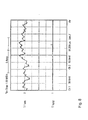
- FIG. 8 upper curve, shows the sum of the three output currents at the inverter output in front of the filter. The maximum amplitude is only 10% of the Peak value of a phase current. The lower curve shows the sum of the output currents after the filter. As you can see, this output current is excellent high quality and does not couple any negative harmonics into it Network.
- the DC intermediate circuit is connected to the closed harmonic circuit stabilized at the same time.
- the neutral point of the three capacitors has a dormant, in principle the same potential as earth. Because this point is static connected via the inductor to the intermediate circuit, flows over this Equalizing current when the potential of the DC link changes. Jumping Potentials are for generators that feed into the DC link, detrimental, because by voltage changes (dU / dt) a capacitive current would flow through the insulation and cause long-term insulation damage.
- An inverter according to the invention is preferred in an electrical energy generating system, such as a wind turbine used.
- Such electrical energy generating systems then provide the network with a Electricity of the highest quality, which also has the consequence that the respective network operator Fewer measures must be taken to ensure electricity quality.
Abstract
Description
Die Erfindung betrifft einen Wechselrichter bzw. ein Ausgangsfilter für Wechselrichter. Der Ausgangsstrom eines Wechselrichters für höhere Leistungen weist in der Regel eine ganze Reihe von Stromoberschwingungen auf. Diese Oberschwingungen sind störend und besonders wenn größere Leistung über Wechselrichter in ein Netz eingespeist werden müssen, treten sie unangenehm auf.The invention relates to an inverter or an output filter for inverters. The output current of an inverter for higher power points in usually a whole bunch of current harmonics up. These harmonics are annoying and especially if greater power over inverter be fed into a network, they occur unpleasantly.
In Figur 1 ist ein Wechselrichter mit einer Ausgangsdrossel und einem Kondensatorfilternetzwerk gezeigt, der den vorbeschriebenen technischen Nachteil von Wechselrichtern deutlich verkleinert und die Stromqualität erheblich verbessert. Die Leistungsschalter T1 bis T6 und die hierzu parallel geschalteten Dioden werden mittels einer Pulsweitenmodulation der Leistungsschalter so geschaltet, dass am Ausgang des Wechselrichters drei sinusförmige Ausgangsströme-Phasen U, V, W entstehen. Die Form des Ausgangsstromes wird durch gezieltes Ein- bzw. Ausschalten der einzelnen Schalter T1 - T6 einer Sinusschwingung angenähert. Dabei entstehen jedoch durch die zwangsläufigen Abweichungen vom Sollwert die genannten Oberschwingungen. FIG. 1 shows an inverter with an output choke and a capacitor filter network shown, the above-described technical disadvantage of inverters significantly reduced and the power quality significantly improved. The power switches T1 to T6 and the diodes connected in parallel therewith be switched by means of a pulse width modulation of the circuit breaker, that at the output of the inverter three sinusoidal output currents phases U, V, W arise. The shape of the output current is determined by Switching the individual switches T1-T6 on or off approximates to a sinusoidal oscillation. However, due to the inevitable deviations from the Setpoint the mentioned harmonics.
Diese erzeugten Oberschwingungen sind im Dreiphasennetz in jedem Augenblick in der Summe gleich null. Dies ist in jedem Fall so, weil keine anderen Stromwege (andere elektrische Kreise) vorhanden sind. Es entstehen dabei nur symmetrische Oberschwingungen. Durch Filterkreise - wie auch in Figur 1 ausgangsseitig dargestellt - wird dann versucht, diese Oberschwingungen zu kompensieren. Da das elektrische Netz durch die induktiven und kapazitiven Beläge (Komponenten der Übertragungsleitung) ebenfalls teilweise für bestimmte Frequenzen sehr niedrige Impedanzen (Widerstände) aufweist, fließen nach wie vor unerwünscht hohe Anteile der Oberschwingungen in das öffentliche Versorgungsnetz.These generated harmonics are in the three-phase network at every moment in the sum equal to zero. This is in any case so because no other power lines (other electrical circuits) are present. There are only symmetrical Harmonics. By filter circuits - as shown in Figure 1 on the output side - is then tried to compensate for these harmonics. Since that electrical network through the inductive and capacitive pads (components of Transmission line) also partly very low for certain frequencies Impedances (resistors), still flow undesirably high proportions of the harmonics in the public supply network.
Es ist daher Aufgabe der Erfindung, die vorgenannten Nachteile zu beseitigen, so dass in das öffentliche Versorgungsnetz nur noch Strom mit sehr kleinen, wenn möglich gar keinen, Oberschwingungen eingespeist wird. Darüber hinaus soll der Gleichspannungszwischenkreis des Wechselrichters im elektrischen Potential (Spannungswert zum Gehäuse, Erde bzw. zum Drehstromsystem) stabilisiert werden.It is therefore an object of the invention to eliminate the aforementioned disadvantages, so that in the public supply network only electricity with very small, though possible no, harmonics is fed. In addition, the should DC intermediate circuit of the inverter in the electrical potential (Voltage value to the housing, earth or to the three-phase system) to be stabilized.
Zur Lösung der gestellten Aufgabe wird erfindungsgemäß ein Wechselrichter mit
den Merkmalen nach Anspruch 1 vorgeschlagen. Vorteilhafte Weiterbildungen sind
in den Unteransprüchen beschrieben.To achieve the object, an inverter according to the invention
proposed the features of
Mit dem erfindungsgemäßen Wechselrichter werden unsymmetrische Oberschwingungen, Wechselrichter ausgangsseitig erzeugt und in den Gleichstromzwischenkreis zurückgeführt. Zur Erzeugung der unsymmetrischen Oberschwingungen wird zusätzlich zu der am Wechselrichterausgang vorhandenen Drehstromausgangsdrossel eine weitere Wicklung vorgesehen (vierter Schenkel). Diese weitere Wicklung überträgt unsymmetrische Magnetflüsse, die aus den unsymmetrischen Oberschwingungen entstehen. Die Oberschwingungen werden über drei Schwingkreise, beispielsweise drei LC-Glieder, gesammelt. Symmetrische Oberschwingungen werden, falls überhaupt noch vorhanden, mit diesen Schwingkreisen direkt kompensiert. Die unsymmetrischen Oberschwingungen (Σi ≠ 0) werden zum Gleichspannungszwischenkreis zurückgeführt. Die Summe der unsymmetrischen Oberschwingungen wird am Sternpunkt der Schwingkreise (der Filterkondensatoren der Schwingkreise) abgegriffen und über eine Wicklung am vierten Schenkel in die Minusschiene des Gleichspannungszwischenkreises geführt bzw. eingekoppelt. Damit ergibt sich ein geschlossener "Oberschwingungsstromkreislauf', der in Figur 2 zeichnerisch dargestellt ist.With the inverter according to the invention unbalanced harmonics, Inverter generated on the output side and in the DC intermediate circuit recycled. For generating the unbalanced harmonics is in addition to the three-phase output choke on the inverter output another winding provided (fourth leg). This further Winding transmits unbalanced magnetic fluxes that come from the unbalanced Harmonics arise. The harmonics will be over three Oscillation circuits, for example, three LC elements, collected. Symmetric harmonics are, if any, with these resonant circuits directly compensated. The unbalanced harmonics (Σi ≠ 0) become returned to the DC intermediate circuit. The sum of the unbalanced ones Harmonics is at the star point of the resonant circuits (the filter capacitors the resonant circuits) tapped and a winding on the fourth Leg guided in the negative rail of the DC intermediate circuit or coupled. This results in a closed "harmonic current circuit", which is shown in Figure 2 drawing.
Der Summenstrom der unsymmetrischen Oberschwingungen, der am Sternpunkt der Schwingkreise abgegriffen wird, erzeugt im vierten Schenkel der Ausgangsdrossel magnetische Flüsse. Diese magnetischen Flüsse fließen, abhängig von der aktuellen Situation, in die drei Hauptschenkel der Ausgangsdrossel zurück und unterstützen damit die Ausgangsinduktivität. Als Ergebnis stellt sich eine um ca. 5% bis 20% höhere Ausgangsinduktivität als bei einer gewöhnlichen Dreiphasendrossel ein. Da in der vierten Wicklung nur der Oberschwingungsstrom fließt, entstehen hierbei - in Relation zu den Hauptspulen der Drossel - nur sehr kleine Kupferverluste.The summation current of the unbalanced harmonics, that at the neutral point the oscillating circuits is tapped, generated in the fourth leg of the output throttle magnetic rivers. These magnetic fluxes flow, depending on the current situation, in the three main legs of the output choke and back thus support the output inductance. As a result, an approx. 5% to 20% higher output inductance than an ordinary three-phase reactor one. Since only the harmonic current flows in the fourth winding, arise in this case - in relation to the main coils of the choke - only very small copper losses.
Die Erfindung und zweckmäßige Weiterbildungen sowie ihre Vorteile sind in der nachfolgenden Zeichnungsbeschreibung beispielhaft erläutert. Es zeigen:
- Fig. 1
- ein Prinzipschaltbild eines bekannten Wechselrichters;
- Fig. 2
- ein Prinzipschaltbild eines erfindungsgemäßen Wechselrichters;
- Fig. 3
- ein Messdiagramm eines erfindungsgemäßen Wechselrichters;
- Fig. 4
- einen Ausschnitt aus
Figur 3 mit vergrößerter Auflösung; - Fig. 5
- ein Messdiagramm eines erfindungsgemäßen Wechselrichters;
- Fig. 6
- ein Messdiagramm eines erfindungsgemäßen Wechselrichters;
- Fig.7
- ein Schaltbild einer bevorzugten Ausführungsform eines erfindungsgemäßen Wechselrichters;
- Fig. 8
- ein Strommessdiagramm für den Wechselrichter und Netzstrom.
- Fig. 1
- a schematic diagram of a known inverter;
- Fig. 2
- a schematic diagram of an inverter according to the invention;
- Fig. 3
- a measurement diagram of an inverter according to the invention;
- Fig. 4
- a detail of Figure 3 with increased resolution;
- Fig. 5
- a measurement diagram of an inverter according to the invention;
- Fig. 6
- a measurement diagram of an inverter according to the invention;
- Figure 7
- a circuit diagram of a preferred embodiment of an inverter according to the invention;
- Fig. 8
- a current measurement diagram for the inverter and mains current.
Figur 1 zeigt das Schaltbild eines bekannten Wechselrichters, welcher durch die Antiparallelschaltung der Leistungsschalter T1 bis T6 mit jeweils einer Diode D1-D6 einen Vierquadrantenbetrieb ermöglicht und somit als Schaltung sehr vielseitig einsetzbar ist. Zur Erzeugung der positiven Halbwelle des Ausgangsstroms wird bei dem bekannten Wechselrichter eine aufeinanderfolgende Ein- und Ausschaltung der Schalter Tn (n= 1, 3, 5) und Tn+1 (n=2, 4, 6) vorgenommen. Für eine Halbwelle des Ausgangsstroms der U-Phase des Drehstroms bedeutet dies, dass mehrmals während einer Halbwelle aufeinanderfolgend T1 und T6 an- bzw. ausgeschaltet werden. Den Leistungsschaltern ist ein Gleichspannungszwischenkreis mit zwei in Reihe geschalteten Elektrolyt-Kondensatoren C4 und C5 zur Einspeisung der Gleichspannung + Ud und - Ud vorgeschaltet. Ausgangsseitig weist der Wechselrichter eine Ausgangsdrossel LA (LAU, LAV, LAW) sowie einen nachgeschalteten Filter, bestehend aus drei Kondensatoren C6, C7, C8, die zwischen den jeweiligen Phasen angeordnet sind, auf. Wie bereits beschrieben, wird die Form des dreiphasigen Ausgangsstroms U, V, W durch ein gezieltes Ein- und Ausschalten der einzelnen Leistungsschalter T1 bis T6 einer Sinusschwingung angenähert. Dabei entstehen jedoch durch die zwangsläufigen Abweichungen vom Sollwert Oberschwingungen. Diese erzeugten Oberschwingungen sind im Dreiphasennetz in jedem Augenblick in ihrer Summe gleich oder nahezu null. Dies ist so, weil keine anderen Stromwege vorhanden sind. Die auftretenden Oberschwingungen sind jedoch stets symmetrisch und durch den Kondensatorfilterkreis wird versucht, diese Oberschwingungen zu kompensieren. Da aber das elektrische Netz durch die induktiven und kapazitiven Beläge (Komponenten der Übertragungsleitung) ebenfalls teilweise für bestimmte Frequenzen sehr niedrige Impedanzen (Widerstände) aufweist, fließen nach wie vor hohe Anteile der Oberschwingungen in das öffentliche Versorgungsnetz, was sehr unerwünscht ist. Figure 1 shows the circuit diagram of a known inverter, which by the Anti-parallel connection of the power switches T1 to T6, each with a diode D1-D6 allows a four-quadrant operation and thus very versatile as a circuit can be used. To generate the positive half wave of the output current is in the known inverter a successive switching on and off the switch Tn (n = 1, 3, 5) and Tn + 1 (n = 2, 4, 6) made. For one Half-wave of the output current of the U-phase of the three-phase current, this means that several times during a half-wave successively switched on and off T1 and T6 become. The circuit breakers is a DC voltage intermediate circuit with two series-connected electrolytic capacitors C4 and C5 for feeding the DC voltage + Ud and - Ud upstream. On the output side, the inverter points an output choke LA (LAU, LAV, LAW) and a downstream Filter consisting of three capacitors C6, C7, C8, which between each Phases are arranged on. As already described, the shape of the three-phase output current U, V, W by a selective switching on and off the individual circuit breaker T1 to T6 approximated to a sine wave. However, this is caused by the inevitable deviations from the setpoint Harmonics. These generated harmonics are in the three-phase network in each moment in their sum equal or almost zero. This is so because no other power paths are available. The occurring harmonics are but always symmetrical and through the capacitor filter circuit is trying this Compensate for harmonics. But because the electrical network through the inductive and capacitive pads (components of the transmission line) also partially for certain frequencies very low impedances (resistors) high levels of harmonics continue to flow into the public sector Supply network, which is very undesirable.
Figur 2 zeigt das Schaltbild eines erfindungsgemäßen Wechselrichters. Dieser weist wie der bekannte Wechselrichter einen Gleichspannungszwischenkreis, Leistungsschalter T1 - T6 und hierzu parallel geschaltete Dioden D1 - D6 sowie eine Ausgangsdrossel LA auf.FIG. 2 shows the circuit diagram of an inverter according to the invention. This has as the known inverter DC voltage intermediate circuit breaker T1 - T6 and parallel connected diodes D1 - D6 and a Output choke LA on.
Der erfindungsgemäße Wechselrichter erzeugt unsymmetrische Oberschwingungen. Hierzu ist eine zusätzliche Wicklung L4 (zusätzlicher Schenkel) vorgesehen. 1 Dieser vierte Schenkel L4 überträgt die unsymmetrischen Magnetflüsse, die aus den unsymmetrischen Oberschwingungen entstehen. Die Oberschwingungen werden über drei Schwingkreise LC bzw. drei L-C-Glieder, bestehend aus den Induktivitäten L1 bis L3 sowie den Kondensatoren C1 bis C3 und einem gemeinsamen Sternpunkt. Symmetrische Oberschwingungen werden mit diesen Schwingkreisen LC, soweit sie noch vorhanden sind, direkt kompensiert. Unsymmetrische Oberschwingungen L4 (ΣI ≠ 0) werden über den Sternpunkt der Wicklung des vierten Schenkels L4 zugeführt. Diese vierte Wicklung L4 ist mit der Minusschiene des Gleichspannungszwischenkreises verbunden. Die Summe der unsymmetrischen Oberschwingungen wird somit am Sternpunkt der Filterkondensatoren abgegriffen und über die Wicklung am vierten Schenkel L4 in den Gleichspannungszwischenkreis eingekoppelt. Hiermit ergibt sich ein geschlossener Oberschwingungsstromkreislauf für die unsymmetrischen Oberschwingungen.The inverter according to the invention generates unbalanced harmonics. For this purpose, an additional winding L4 (additional leg) is provided. 1 This fourth leg L4 transmits the unbalanced magnetic fluxes that out the unbalanced harmonics arise. The harmonics will be over three oscillating circuits LC or three L-C-links, consisting of the inductivities L1 to L3 and the capacitors C1 to C3 and a common Star point. Symmetric harmonics are with these resonant circuits LC, as far as they are still available, directly compensated. Unbalanced harmonics L4 (ΣI ≠ 0) will be over the neutral point of the winding of the fourth Supplied to Schenkel's L4. This fourth winding L4 is connected to the minus rail of the DC DC link connected. The sum of the unbalanced ones Harmonics is thus tapped at the star point of the filter capacitors and via the winding on the fourth leg L4 in the DC intermediate circuit coupled. This results in a closed harmonic current circuit for the unbalanced harmonics.
Der Summenstrom der unsymmetrischen Oberschwingungen der am Sternpunkt der Kondensatoren abgegriffen wird, erzeugt am vierten Schenkel der Ausgangsdrossel LA magnetische Flüsse. Diese magnetischen Flüsse fließen, LA abhängig von der jeweiligen Situation, in die mit dem vierten Schenkel magnetisch gekoppelten Hauptschenkel der Ausgangsdrossel LA zurück und unterstützen deren Ausgangsinduktivität.The summation current of the unbalanced harmonics at the neutral point the capacitors is tapped, generated on the fourth leg of the output reactor LA magnetic rivers. These magnetic fluxes flow, depending on LA from the particular situation in which magnetically coupled with the fourth leg Main legs of the output inductor LA back and support their output inductance.
Als Ergebnis hieraus erhält man eine um ca. 5-20% höhere Ausgangsinduktivität LA als bei einer gewöhnlichen Dreiphasendrossel. Da in der vierten Wicklung LA4 nur der Oberschwingungsstrom der unsymmetrischen Oberschwingungen fließt, entstehen hierbei nur sehr kleine Kupferverluste, verglichen zu denen in den Hauptspulen LA1, LA2, LA3.As a result, one obtains about 5-20% higher output inductance LA as an ordinary three-phase choke. Because in the fourth winding LA4 only the harmonic current of the unbalanced harmonics flows, Here arise only very small copper losses, compared to those in the Main coils LA1, LA2, LA3.
Figur 3 zeigt ein Messdiagramm des Wechselrichters nach Figur 2. Die obere Kurve zeigt die positive Sinushalbschwingung des Stromes am Wechselrichterausgang. In diesem Fall ist die Hysterese des Stromes konstant und die Schaltfrequenz variabel. Die untere Kurve zeigt die Summe der Oberschwingungen der drei Ausgangsphasen des Wechselrichters, die über den vierten Schenkel in den Gleichspannungszwischenkreis zurückfließen.FIG. 3 shows a measuring diagram of the inverter according to FIG. 2. The upper curve shows the positive sine half-wave of the current at the inverter output. In this case, the hysteresis of the current is constant and the switching frequency variable. The lower curve shows the sum of the harmonics of the three Output phases of the inverter, which over the fourth leg in the Return DC voltage intermediate circuit.
Figur 4 zeigt nochmals einen Teil des Ausgangsstromes des Wechselrichters der
Phase 1 in höherer Auflösung. Hierbei sind deutlich die dreieckförmigen Oberschwingungen
des Ausgangsstromes IWR LA zu erkennen.Figure 4 shows again a part of the output current of the inverter of
Mit dem Schwingkreis, bestehend aus L1 und C1, werden diese Oberschwingungen am Ausgang der Ausgangsinduktivität LA von der (Sinus-) Grundschwingung des Ausgangsstromes getrennt. Die untere Kurve in Figur 4 zeigt den zeitlichen Verlauf des Stromes IL1C1 in L1 und C1.With the resonant circuit, consisting of L1 and C1, these harmonics at the output of the output inductance LA from the (sinusoidal) fundamental the output current separated. The lower curve in Figure 4 shows the temporal Course of the current IL1C1 in L1 and C1.
Figur 5 zeigt das Ergebnis der Trennung der Oberschwingungen vom Hauptstrom (Grundschwingung 50 Hz). Die oberste Kurve zeigt den Ausgangsstrom ohne Oberschwingungen. Dieses sehr gute Ergebnis ist nur mit dem erfindungsgemäßen Oberschwingungskreislauf möglich. Dabei werden, wie in den Figuren zu erkennen, die erzeugten Oberschwingungen vom Wechselrichter nahezu zu 100% in den Gleichspannungszwischenkreis zurückgeführt. Die mittlere Kurve in Figur 5 zeigt den Wechselrichterstrom IWR LA und die untere Kurve in Figur 5 zeigt nochmals den dazugehörigen Oberschwingungsstrom.Figure 5 shows the result of the separation of the harmonics from the main stream (Fundamental 50 Hz). The uppermost curve shows the output current without harmonics. This very good result is only with the invention Harmonic circuit possible. As you can see in the figures, the harmonics generated by the inverter almost 100% in the DC intermediate circuit returned. The middle curve in FIG. 5 shows the inverter current IWR LA and the lower curve in Figure 5 shows again the associated harmonic current.
Figur 6 (untere Kurve) zeigt die Summe der drei Oberschwingungsströme I21, I22 und I23. Dieser Strom, der fast alle Oberschwingungen der drei Phasen beinhaltet, wird nun nochmals genutzt, um die Wirkung der Ausgangsdrossel LA zu erhöhen. Diese Drossel besteht, wie bereits beschrieben, aus den drei Hauptschenkeln LA1, LA2, LA3 für die drei Hauptausgangswicklungen und einem vierten kleinen Tochterschenkel, der nur für die Oberschwingungen vorgesehen ist. Dieser vierte Schenkel führt nur die magnetischen Flüsse, die der Summe der Oberschwingungen entsprechen. Die entsprechende Amplitude dieses Summenstromes der Oberschwingungen ist in Figur 6, untere Kurve dargestellt. Die obere Kurve zeigt den entsprechenden Spannungsverlauf hierzu. Um dies zu erreichen, ist ein Eisenquerschnitt von ca. 20% der Hauptschenkel für den vierten Schenkel ausreichend. Der vierte Schenkel erhöht aber die wirkende Ausgangsinduktivität LA um ca. 5-20%. Hieraus resultiert eine kleinere Baugröße der Ausgangsdrossel LA und ein besserer Wirkungsgrad.FIG. 6 (lower curve) shows the sum of the three harmonic currents I21, I22 and I23. This current, which contains almost all the harmonics of the three phases, is now used again to increase the effect of the output inductor LA. This throttle consists, as already described, of the three main legs LA1, LA2, LA3 for the three main output windings and a fourth small daughter leg, which is intended only for the harmonics. This fourth Thigh leads only the magnetic fluxes, which is the sum of the harmonics correspond. The corresponding amplitude of this summation current of the harmonics is shown in Figure 6, lower curve. The upper curve shows the corresponding voltage curve for this purpose. To achieve this is an iron cross section of about 20% of the main leg sufficient for the fourth leg. Of the fourth leg increases but the acting output inductance LA by about 5-20%. This results in a smaller size of the output inductor LA and a better one Efficiency.
Figur 7 zeigt eine Weiterbildung des erfindungsgemäßen Wechselrichters. Die Ausgangsdrossel ist hierbei zweiteilig aufgebaut und besteht aus einer Vierschenkeldrossel und einer hierzu in Reihe geschalteten kompensierten Dreiphasendrossel LA2. Für unsymmetrische Oberschwingungsströme können vorteilhaft stromkompensierte Drosseln eingesetzt werden. Da die Summe des Netzstromes (Dreiphasenstrom) gleich null ist, wird die Drossel nicht mit den sehr hohen Grundschwingungen belastet (vormagnetisiert). Somit kann mit wenig Aufwand eine hohe Induktivität aufgebaut werden.FIG. 7 shows a development of the inverter according to the invention. The Output choke is in this case constructed in two parts and consists of a four-limb throttle and a series-connected compensated three-phase reactor LA2. For unbalanced harmonic currents can be advantageous current-compensated Chokes are used. Since the sum of the mains current (three-phase current) is zero, the throttle will not start with the very high fundamental frequencies loaded (premagnetized). Thus, with little effort a high Inductance are built.
Figur 8, obere Kurve, zeigt die Summe der drei Ausgangsströme am Wechselrichterausgang vor dem Filter. Die maximale Amplitude beträgt hierbei nur 10% des Spitzenwertes eines Phasenstromes. Die untere Kurve zeigt die Summe der Ausgangsströme nach dem Filter. Wie zu sehen, ist dieser Ausgangsstrom von ausgezeichnet hoher Qualität und koppelt keine negativen Oberschwingungen in das Netz ein.FIG. 8, upper curve, shows the sum of the three output currents at the inverter output in front of the filter. The maximum amplitude is only 10% of the Peak value of a phase current. The lower curve shows the sum of the output currents after the filter. As you can see, this output current is excellent high quality and does not couple any negative harmonics into it Network.
Der Gleichspannungszwischenkreis wird mit dem geschlossenen Oberschwingungskreis auch gleichzeitig stabilisiert. Der Sternpunkt der drei Kondensatoren hat ein ruhendes, im Prinzip das gleiche Potential wie Erde. Da dieser Punkt statisch über die Induktivität mit dem Zwischenkreis verbunden ist, fließt hierüber ein Ausgleichsstrom, wenn das Potential des Zwischenkreises sich ändert. Springende Potentiale sind für Generatoren, die in den Gleichspannungszwischenkreis einspeisen, schädlich, da durch Spannungsänderungen (dU/dt) ein kapazitiver Strom durch die Isolation fließen würde und langfristig Isolationsschäden verursacht.The DC intermediate circuit is connected to the closed harmonic circuit stabilized at the same time. The neutral point of the three capacitors has a dormant, in principle the same potential as earth. Because this point is static connected via the inductor to the intermediate circuit, flows over this Equalizing current when the potential of the DC link changes. Jumping Potentials are for generators that feed into the DC link, detrimental, because by voltage changes (dU / dt) a capacitive current would flow through the insulation and cause long-term insulation damage.
Bevorzugt werden ein erfindungsgemäßer Wechselrichter in einem elektrische Energie erzeugenden System, beispielsweise eine Windkraftanlage, eingesetzt. Solche elektrische Energie erzeugende Systeme versorgen dann das Netz mit einem Strom höchster Qualität, was auch zur Folge hat, dass der jeweilige Netzbetreiber weniger Maßnahmen zur Stromqualitätssicherung vornehmen muss.An inverter according to the invention is preferred in an electrical energy generating system, such as a wind turbine used. Such electrical energy generating systems then provide the network with a Electricity of the highest quality, which also has the consequence that the respective network operator Fewer measures must be taken to ensure electricity quality.
Claims (13)
dadurch gekennzeichnet, dass der Schwingkreis über einen Abgriff verfügt, über den unsymmetrische Oberschwingungen, die am Ausgang des Wechselrichters auftreten, in den Gleichspannungszwischenkreis zurückgeführt werden.Inverter according to claim 1 or 2,
characterized in that the resonant circuit has a tap, are returned via the unbalanced harmonics that occur at the output of the inverter in the DC voltage intermediate circuit.
bei dem die Ausgangsdrossel unsymmetrische Magnetflüsse, die aus den unsymmetrischen Oberschwingungen entstehen, überträgt.Inverter according to claim 4,
in which the output choke transmits unbalanced magnetic fluxes that arise from the unbalanced harmonics.
bei dem die Ausgangsdrossel aus m + 1 Schenkeln besteht, wobei m eine natürliche Zahl ist, wobei jeder Drehstromphase ein Schenkel zugeordnet ist und mittels des m + ersten Schenkel die unsymmetrischen Magnetflüsse, die aus den unsymmetrischen Oberschwingungen entstehen, übertragen werden.Inverter according to claim 5 or 6,
wherein the output choke of m + 1 legs, where m is a natural number, each phase of three phase is associated with a leg and by means of the m + first leg, the unbalanced magnetic fluxes that arise from the unbalanced harmonics transmitted.
bei dem die m + 1 Schenkel miteinander magnetisch gekoppelt sind und magnetische Flüsse, die im m + ersten Schenkel auftreten, in die m Schenkel der Ausgangsdrossel zurückfließen.Inverter according to one of the preceding claims,
in which the m + 1 legs are magnetically coupled to one another and magnetic flows which occur in the m + first leg flow back into the m legs of the output throttle.
bei dem der m + erste Schenkel nur von Oberschwingungsstrom durchflossen wird.Inverter according to one of the preceding claims,
in which the m + first leg is only traversed by harmonic current.
dadurch gekennzeichnet, dass die Ausgangsdrossel eine stromkompensierte Drossel ist.Inverter according to one of the preceding claims,
characterized in that the output choke is a current-compensated choke.
dadurch gekennzeichnet, dass der Gleichspannungszwischenkreis mit dem geschlossenen Oberschwingungskreis stabilisiert wird.Inverter according to one of the preceding claims,
characterized in that the DC voltage intermediate circuit is stabilized with the closed harmonic circuit.
Erzeugung eines Wechsels- und Drehstromes nach einem der vorhergehenden Ansprüche.Electric power generating system with an inverter for
Generation of a alternating and three-phase current according to one of the preceding claims.
Priority Applications (1)
| Application Number | Priority Date | Filing Date | Title |
|---|---|---|---|
| CY20151100514T CY1116403T1 (en) | 1999-02-25 | 2015-06-12 | Alternating current inverter without harmonic components |
Applications Claiming Priority (3)
| Application Number | Priority Date | Filing Date | Title |
|---|---|---|---|
| DE19908124 | 1999-02-25 | ||
| DE19908124A DE19908124C2 (en) | 1999-02-25 | 1999-02-25 | Inverters without harmonics |
| EP99950783A EP1078445B1 (en) | 1999-02-25 | 1999-10-27 | Inverter |
Related Parent Applications (1)
| Application Number | Title | Priority Date | Filing Date |
|---|---|---|---|
| EP99950783A Division EP1078445B1 (en) | 1999-02-25 | 1999-10-27 | Inverter |
Publications (3)
| Publication Number | Publication Date |
|---|---|
| EP1598924A2 true EP1598924A2 (en) | 2005-11-23 |
| EP1598924A3 EP1598924A3 (en) | 2008-04-09 |
| EP1598924B1 EP1598924B1 (en) | 2015-04-22 |
Family
ID=7898814
Family Applications (2)
| Application Number | Title | Priority Date | Filing Date |
|---|---|---|---|
| EP99950783A Expired - Lifetime EP1078445B1 (en) | 1999-02-25 | 1999-10-27 | Inverter |
| EP20050106885 Expired - Lifetime EP1598924B1 (en) | 1999-02-25 | 1999-10-27 | Inverter without harmonics |
Family Applications Before (1)
| Application Number | Title | Priority Date | Filing Date |
|---|---|---|---|
| EP99950783A Expired - Lifetime EP1078445B1 (en) | 1999-02-25 | 1999-10-27 | Inverter |
Country Status (17)
| Country | Link |
|---|---|
| US (1) | US6452819B1 (en) |
| EP (2) | EP1078445B1 (en) |
| JP (1) | JP3571654B2 (en) |
| AR (1) | AR022774A1 (en) |
| AT (1) | ATE315843T1 (en) |
| AU (1) | AU758259B2 (en) |
| BR (1) | BR9909183A (en) |
| CA (1) | CA2310391C (en) |
| CY (2) | CY1105730T1 (en) |
| DE (2) | DE19908124C2 (en) |
| DK (2) | DK1078445T3 (en) |
| ES (2) | ES2253918T3 (en) |
| HK (1) | HK1034818A1 (en) |
| NZ (1) | NZ504757A (en) |
| PT (1) | PT1598924E (en) |
| TR (1) | TR200001595T1 (en) |
| WO (1) | WO2000051225A1 (en) |
Cited By (3)
| Publication number | Priority date | Publication date | Assignee | Title |
|---|---|---|---|---|
| DE202011101851U1 (en) | 2011-05-18 | 2012-08-20 | Block Transformatoren-Elektronik Gmbh | filter circuit |
| DE102013208911A1 (en) * | 2013-05-14 | 2014-11-20 | Schmidbauer Transformatoren und Gerätebau GmbH | Multi-phase choke with integrated interference suppression transformer |
| DE102015104660A1 (en) | 2015-03-26 | 2016-09-29 | Block Transformatoren-Elektronik Gmbh | throttle arrangement |
Families Citing this family (16)
| Publication number | Priority date | Publication date | Assignee | Title |
|---|---|---|---|---|
| DE10034054A1 (en) * | 2000-07-13 | 2002-04-04 | Epcos Ag | Mains filter has each phase input connected to phase output via filter inductance connected on input side to earth conductor via filter capacitor, auxiliary inductances |
| DE20222013U1 (en) * | 2002-06-07 | 2010-11-04 | Epcos Ag | Current-compensated choke and circuit arrangement with the current-compensated choke |
| FI116178B (en) * | 2002-08-22 | 2005-09-30 | Abb Oy | Output choke assembly for inverter |
| US6816394B2 (en) * | 2003-03-05 | 2004-11-09 | Natus Technology Corp. | Approximated sinusoidal waveform inverter |
| ATE349102T1 (en) * | 2004-09-09 | 2007-01-15 | Abb Oy | CONTROL WITHOUT SPEED SENSOR OF AN INDUCTION MACHINE USING A PBM INVERTER WITH LC OUTPUT FILTER |
| JP5422178B2 (en) * | 2008-11-12 | 2014-02-19 | 株式会社東芝 | Grid interconnection inverter |
| FR2945166B1 (en) * | 2009-04-29 | 2014-03-07 | Converteam Technology Ltd | PASSIVE FILTER AND POWER SUPPLY SYSTEM FOR AN ELECTRIC MOTOR COMPRISING SUCH A FILTER |
| TWI454028B (en) * | 2010-01-13 | 2014-09-21 | Toshiba Kk | System interconnection converter |
| US8618694B2 (en) * | 2010-06-30 | 2013-12-31 | Vestas Wind Systems A/S | System, method, and computer program product for utilizing a wind park as a variable power system stabilizer |
| DE102010040835A1 (en) * | 2010-09-15 | 2012-03-15 | Robert Bosch Gmbh | Filter i.e. low pass filter, for use as output filter for pulse inverter in compressor system for e.g. three-phase alternating current in three-phase motor, has capacitors connected between two conductors so as to form delta connection |
| US20130039105A1 (en) * | 2011-08-09 | 2013-02-14 | Hamilton Sundstrand Corporation | Filter circuit for a multi-phase ac input |
| DE102012207557A1 (en) * | 2012-05-07 | 2013-11-07 | Wobben Properties Gmbh | Three-phase choke |
| DE102014205845A1 (en) | 2013-03-28 | 2014-10-02 | Robert Bosch Gmbh | Control device for controlling an electric motor and method for compensation of a noise signal in a drive circuit for an electric motor |
| US9800133B2 (en) * | 2016-03-22 | 2017-10-24 | Infineon Technologies Ag | Active common mode cancellation |
| DE102016107295A1 (en) * | 2016-04-20 | 2017-10-26 | Wobben Properties Gmbh | Three-phase choke coil |
| DE102017109728A1 (en) | 2017-05-05 | 2018-11-08 | Wobben Properties Gmbh | Wind energy plant with overloadable inverter system |
Citations (9)
| Publication number | Priority date | Publication date | Assignee | Title |
|---|---|---|---|---|
| US4677401A (en) * | 1984-07-19 | 1987-06-30 | Fuji Electrochemical Co., Ltd. | Noise filter for three-phase four-wire system |
| EP0598465A2 (en) * | 1992-11-16 | 1994-05-25 | International Power Machines | Method and apparatus for harmonic distortion correction |
| WO1994018683A1 (en) * | 1993-02-12 | 1994-08-18 | Regents Of The University Of Minnesota | System for reducing harmonics by harmonic current injection |
| DE29506951U1 (en) * | 1995-04-25 | 1995-06-22 | Siemens Ag | Circuitry for interference suppression |
| US5499178A (en) * | 1991-12-16 | 1996-03-12 | Regents Of The University Of Minnesota | System for reducing harmonics by harmonic current injection |
| US5513090A (en) * | 1994-11-15 | 1996-04-30 | Electric Power Research Institute, Inc. | Hybrid series active, parallel passive, power line conditioner for harmonic isolation between a supply and a load |
| EP0758161A2 (en) * | 1995-08-07 | 1997-02-12 | Eaton Corporation | Conducted emission radiation suppression in inverter drives |
| US5661390A (en) * | 1995-06-23 | 1997-08-26 | Electric Power Research Institute, Inc. | Inverter-fed motor drive with EMI suppression |
| US5831842A (en) * | 1996-09-18 | 1998-11-03 | President Of Okayama University | Active common mode canceler |
Family Cites Families (3)
| Publication number | Priority date | Publication date | Assignee | Title |
|---|---|---|---|---|
| DE2446635A1 (en) * | 1974-09-30 | 1976-04-08 | Siemens Ag | INVERTER ARRANGEMENT WITH TWO THREE-PHASE CONTROLLED INVERTERS |
| US5568371A (en) * | 1994-09-29 | 1996-10-22 | Texas A&M University System | Active harmonic power filter apparatus and method |
| DE19637290A1 (en) * | 1996-09-13 | 1998-03-19 | Asea Brown Boveri | Converter circuit arrangement with load-side filter |
-
1999
- 1999-02-25 DE DE19908124A patent/DE19908124C2/en not_active Expired - Lifetime
- 1999-10-27 PT PT51068856T patent/PT1598924E/en unknown
- 1999-10-27 AU AU63427/99A patent/AU758259B2/en not_active Ceased
- 1999-10-27 ES ES99950783T patent/ES2253918T3/en not_active Expired - Lifetime
- 1999-10-27 BR BR9909183-6A patent/BR9909183A/en not_active Application Discontinuation
- 1999-10-27 NZ NZ504757A patent/NZ504757A/en not_active IP Right Cessation
- 1999-10-27 WO PCT/EP1999/008118 patent/WO2000051225A1/en active IP Right Grant
- 1999-10-27 DK DK99950783T patent/DK1078445T3/en active
- 1999-10-27 ES ES05106885.6T patent/ES2541435T3/en not_active Expired - Lifetime
- 1999-10-27 EP EP99950783A patent/EP1078445B1/en not_active Expired - Lifetime
- 1999-10-27 TR TR2000/01595T patent/TR200001595T1/en unknown
- 1999-10-27 DK DK05106885.6T patent/DK1598924T3/en active
- 1999-10-27 AT AT99950783T patent/ATE315843T1/en active
- 1999-10-27 JP JP2000601728A patent/JP3571654B2/en not_active Expired - Lifetime
- 1999-10-27 EP EP20050106885 patent/EP1598924B1/en not_active Expired - Lifetime
- 1999-10-27 CA CA002310391A patent/CA2310391C/en not_active Expired - Lifetime
- 1999-10-27 DE DE59913048T patent/DE59913048D1/en not_active Expired - Lifetime
- 1999-10-27 US US09/601,850 patent/US6452819B1/en not_active Expired - Lifetime
-
2000
- 2000-02-25 AR ARP000100849A patent/AR022774A1/en active IP Right Grant
-
2001
- 2001-08-06 HK HK01105437A patent/HK1034818A1/en not_active IP Right Cessation
-
2006
- 2006-03-28 CY CY20061100429T patent/CY1105730T1/en unknown
-
2015
- 2015-06-12 CY CY20151100514T patent/CY1116403T1/en unknown
Patent Citations (9)
| Publication number | Priority date | Publication date | Assignee | Title |
|---|---|---|---|---|
| US4677401A (en) * | 1984-07-19 | 1987-06-30 | Fuji Electrochemical Co., Ltd. | Noise filter for three-phase four-wire system |
| US5499178A (en) * | 1991-12-16 | 1996-03-12 | Regents Of The University Of Minnesota | System for reducing harmonics by harmonic current injection |
| EP0598465A2 (en) * | 1992-11-16 | 1994-05-25 | International Power Machines | Method and apparatus for harmonic distortion correction |
| WO1994018683A1 (en) * | 1993-02-12 | 1994-08-18 | Regents Of The University Of Minnesota | System for reducing harmonics by harmonic current injection |
| US5513090A (en) * | 1994-11-15 | 1996-04-30 | Electric Power Research Institute, Inc. | Hybrid series active, parallel passive, power line conditioner for harmonic isolation between a supply and a load |
| DE29506951U1 (en) * | 1995-04-25 | 1995-06-22 | Siemens Ag | Circuitry for interference suppression |
| US5661390A (en) * | 1995-06-23 | 1997-08-26 | Electric Power Research Institute, Inc. | Inverter-fed motor drive with EMI suppression |
| EP0758161A2 (en) * | 1995-08-07 | 1997-02-12 | Eaton Corporation | Conducted emission radiation suppression in inverter drives |
| US5831842A (en) * | 1996-09-18 | 1998-11-03 | President Of Okayama University | Active common mode canceler |
Cited By (4)
| Publication number | Priority date | Publication date | Assignee | Title |
|---|---|---|---|---|
| DE202011101851U1 (en) | 2011-05-18 | 2012-08-20 | Block Transformatoren-Elektronik Gmbh | filter circuit |
| DE102011102134A1 (en) | 2011-05-18 | 2012-11-22 | Block Transformatoren-Elektronik Gmbh | Filter circuit for coupling between alternating current voltage source and power pulse current converter circuit, has first and third inductors arranged on same leg of one common iron core and are wound together and are interconnected |
| DE102013208911A1 (en) * | 2013-05-14 | 2014-11-20 | Schmidbauer Transformatoren und Gerätebau GmbH | Multi-phase choke with integrated interference suppression transformer |
| DE102015104660A1 (en) | 2015-03-26 | 2016-09-29 | Block Transformatoren-Elektronik Gmbh | throttle arrangement |
Also Published As
| Publication number | Publication date |
|---|---|
| CA2310391C (en) | 2003-10-14 |
| JP3571654B2 (en) | 2004-09-29 |
| AU6342799A (en) | 2000-09-14 |
| AU758259B2 (en) | 2003-03-20 |
| WO2000051225A1 (en) | 2000-08-31 |
| ATE315843T1 (en) | 2006-02-15 |
| ES2253918T3 (en) | 2006-06-01 |
| NZ504757A (en) | 2003-03-28 |
| DK1078445T3 (en) | 2006-05-22 |
| EP1598924A3 (en) | 2008-04-09 |
| HK1034818A1 (en) | 2001-11-02 |
| CY1105730T1 (en) | 2010-12-22 |
| DE19908124A1 (en) | 2000-09-07 |
| ES2541435T3 (en) | 2015-07-20 |
| EP1598924B1 (en) | 2015-04-22 |
| DE59913048D1 (en) | 2006-04-06 |
| BR9909183A (en) | 2000-12-05 |
| CA2310391A1 (en) | 2000-08-25 |
| CY1116403T1 (en) | 2017-02-08 |
| EP1078445A1 (en) | 2001-02-28 |
| DE19908124C2 (en) | 2003-04-30 |
| TR200001595T1 (en) | 2001-01-22 |
| PT1598924E (en) | 2015-09-14 |
| EP1078445B1 (en) | 2006-01-11 |
| JP2002538752A (en) | 2002-11-12 |
| DK1598924T3 (en) | 2015-06-29 |
| AR022774A1 (en) | 2002-09-04 |
| US6452819B1 (en) | 2002-09-17 |
Similar Documents
| Publication | Publication Date | Title |
|---|---|---|
| DE19908124C2 (en) | Inverters without harmonics | |
| EP1118151B1 (en) | Electrical power transmission system | |
| DE2950247C2 (en) | Power supply system | |
| EP2815497B1 (en) | Grid feed apparatus, energy feed system and method for operating a grid feed apparatus | |
| EP2580858A2 (en) | Circuit topology for a phase connection of an inverter | |
| DE102019130838A1 (en) | A filter arrangement | |
| DE3241413A1 (en) | POWER SUPPLY CIRCUIT | |
| DE102019130839A1 (en) | An inductor assembly | |
| DE2825240C2 (en) | Ripple control system | |
| DE2843528A1 (en) | POWER INVERTER | |
| EP2421135A2 (en) | Step-down-converter, DC-AC-converter assembly and method for operating the same | |
| DE102013208911A1 (en) | Multi-phase choke with integrated interference suppression transformer | |
| DE3810870A1 (en) | DEVICE FOR FORMING ELECTRICAL ENERGY | |
| EP2281206A2 (en) | Vlf test generator | |
| EP3531547B1 (en) | Operating circuit for coupling of a synchronous machine with a voltage network and method for the operation of same | |
| DE3149418A1 (en) | "SELF-COMMUTING INVERTER" | |
| DE112015000929T5 (en) | Device and method for reducing harmonics | |
| DE102013200520A1 (en) | Inverter arrangement for converting direct current or direct voltage into alternating current, has superposing unit with output unit connected with square wave generators such that square wave signals are stepped to sinusoidal signal | |
| DE1463259C3 (en) | Power supply device for alternating current of constant frequency with an alternating current generator that can be driven at variable speed | |
| AT269995B (en) | Arrangement with a converter | |
| DE2433825B2 (en) | Devices for supplying energy and improving the power factor of AC networks | |
| DE1906432A1 (en) | Converter for electrical power | |
| AT408496B (en) | Three-phase pulsed rectifier system with little reaction on the mains system, for a high input voltage | |
| DE2719563C3 (en) | Converter arrangement for converting an input voltage into a controllable DC output voltage | |
| AT145447B (en) | Arrangement for commutation in rectifiers or inverters that work with grid-controlled vapor or gas discharge paths and synchronous isolators. |
Legal Events
| Date | Code | Title | Description |
|---|---|---|---|
| PUAI | Public reference made under article 153(3) epc to a published international application that has entered the european phase |
Free format text: ORIGINAL CODE: 0009012 |
|
| AC | Divisional application: reference to earlier application |
Ref document number: 1078445 Country of ref document: EP Kind code of ref document: P |
|
| AK | Designated contracting states |
Kind code of ref document: A2 Designated state(s): AT BE CH CY DE DK ES FI FR GB GR IE IT LI LU MC NL PT SE |
|
| PUAL | Search report despatched |
Free format text: ORIGINAL CODE: 0009013 |
|
| AK | Designated contracting states |
Kind code of ref document: A3 Designated state(s): AT BE CH CY DE DK ES FI FR GB GR IE IT LI LU MC NL PT SE |
|
| 17P | Request for examination filed |
Effective date: 20081009 |
|
| AKX | Designation fees paid |
Designated state(s): AT BE CH CY DE DK ES FI FR GB GR IE IT LI LU MC NL PT SE |
|
| 17Q | First examination report despatched |
Effective date: 20081125 |
|
| GRAP | Despatch of communication of intention to grant a patent |
Free format text: ORIGINAL CODE: EPIDOSNIGR1 |
|
| INTG | Intention to grant announced |
Effective date: 20141125 |
|
| RAP1 | Party data changed (applicant data changed or rights of an application transferred) |
Owner name: WOBBEN PROPERTIES GMBH |
|
| RIN1 | Information on inventor provided before grant (corrected) |
Inventor name: WOBBEN, ALOYS |
|
| GRAS | Grant fee paid |
Free format text: ORIGINAL CODE: EPIDOSNIGR3 |
|
| GRAA | (expected) grant |
Free format text: ORIGINAL CODE: 0009210 |
|
| AC | Divisional application: reference to earlier application |
Ref document number: 1078445 Country of ref document: EP Kind code of ref document: P |
|
| AK | Designated contracting states |
Kind code of ref document: B1 Designated state(s): AT BE CH CY DE DK ES FI FR GB GR IE IT LI LU MC NL PT SE |
|
| REG | Reference to a national code |
Ref country code: GB Ref legal event code: FG4D Free format text: NOT ENGLISH |
|
| REG | Reference to a national code |
Ref country code: CH Ref legal event code: EP Ref country code: CH Ref legal event code: NV Representative=s name: WEINMANN ZIMMERLI, CH |
|
| REG | Reference to a national code |
Ref country code: AT Ref legal event code: REF Ref document number: 723767 Country of ref document: AT Kind code of ref document: T Effective date: 20150515 |
|
| REG | Reference to a national code |
Ref country code: IE Ref legal event code: FG4D Free format text: LANGUAGE OF EP DOCUMENT: GERMAN |
|
| REG | Reference to a national code |
Ref country code: DE Ref legal event code: R096 Ref document number: 59915427 Country of ref document: DE Effective date: 20150603 |
|
| REG | Reference to a national code |
Ref country code: NL Ref legal event code: T3 |
|
| REG | Reference to a national code |
Ref country code: NL Ref legal event code: T3 |
|
| REG | Reference to a national code |
Ref country code: DK Ref legal event code: T3 Effective date: 20150622 |
|
| REG | Reference to a national code |
Ref country code: ES Ref legal event code: FG2A Ref document number: 2541435 Country of ref document: ES Kind code of ref document: T3 Effective date: 20150720 |
|
| REG | Reference to a national code |
Ref country code: SE Ref legal event code: TRGR |
|
| REG | Reference to a national code |
Ref country code: GR Ref legal event code: EP Ref document number: 20150401171 Country of ref document: GR Effective date: 20150720 |
|
| REG | Reference to a national code |
Ref country code: PT Ref legal event code: SC4A Free format text: AVAILABILITY OF NATIONAL TRANSLATION Effective date: 20150721 |
|
| REG | Reference to a national code |
Ref country code: FR Ref legal event code: PLFP Year of fee payment: 17 |
|
| RAP2 | Party data changed (patent owner data changed or rights of a patent transferred) |
Owner name: WOBBEN PROPERTIES GMBH |
|
| REG | Reference to a national code |
Ref country code: DE Ref legal event code: R097 Ref document number: 59915427 Country of ref document: DE |
|
| PLBE | No opposition filed within time limit |
Free format text: ORIGINAL CODE: 0009261 |
|
| STAA | Information on the status of an ep patent application or granted ep patent |
Free format text: STATUS: NO OPPOSITION FILED WITHIN TIME LIMIT |
|
| 26N | No opposition filed |
Effective date: 20160125 |
|
| PG25 | Lapsed in a contracting state [announced via postgrant information from national office to epo] |
Ref country code: MC Free format text: LAPSE BECAUSE OF FAILURE TO SUBMIT A TRANSLATION OF THE DESCRIPTION OR TO PAY THE FEE WITHIN THE PRESCRIBED TIME-LIMIT Effective date: 20150422 |
|
| REG | Reference to a national code |
Ref country code: FR Ref legal event code: PLFP Year of fee payment: 18 |
|
| REG | Reference to a national code |
Ref country code: FR Ref legal event code: PLFP Year of fee payment: 19 |
|
| PGFP | Annual fee paid to national office [announced via postgrant information from national office to epo] |
Ref country code: LU Payment date: 20171023 Year of fee payment: 19 |
|
| PGFP | Annual fee paid to national office [announced via postgrant information from national office to epo] |
Ref country code: FI Payment date: 20171018 Year of fee payment: 19 |
|
| PGFP | Annual fee paid to national office [announced via postgrant information from national office to epo] |
Ref country code: IT Payment date: 20171020 Year of fee payment: 19 Ref country code: BE Payment date: 20171023 Year of fee payment: 19 Ref country code: CH Payment date: 20171023 Year of fee payment: 19 Ref country code: GR Payment date: 20171026 Year of fee payment: 19 |
|
| PGFP | Annual fee paid to national office [announced via postgrant information from national office to epo] |
Ref country code: CY Payment date: 20171020 Year of fee payment: 19 |
|
| REG | Reference to a national code |
Ref country code: FR Ref legal event code: PLFP Year of fee payment: 20 |
|
| PGFP | Annual fee paid to national office [announced via postgrant information from national office to epo] |
Ref country code: NL Payment date: 20181022 Year of fee payment: 20 |
|
| PGFP | Annual fee paid to national office [announced via postgrant information from national office to epo] |
Ref country code: PT Payment date: 20181017 Year of fee payment: 20 Ref country code: SE Payment date: 20181025 Year of fee payment: 20 Ref country code: AT Payment date: 20181019 Year of fee payment: 20 Ref country code: DE Payment date: 20181106 Year of fee payment: 20 Ref country code: DK Payment date: 20181025 Year of fee payment: 20 |
|
| PGFP | Annual fee paid to national office [announced via postgrant information from national office to epo] |
Ref country code: FR Payment date: 20181023 Year of fee payment: 20 Ref country code: GB Payment date: 20181025 Year of fee payment: 20 Ref country code: ES Payment date: 20181122 Year of fee payment: 20 |
|
| REG | Reference to a national code |
Ref country code: CH Ref legal event code: PL |
|
| REG | Reference to a national code |
Ref country code: BE Ref legal event code: MM Effective date: 20181031 |
|
| PG25 | Lapsed in a contracting state [announced via postgrant information from national office to epo] |
Ref country code: LU Free format text: LAPSE BECAUSE OF NON-PAYMENT OF DUE FEES Effective date: 20181027 |
|
| REG | Reference to a national code |
Ref country code: IE Ref legal event code: MM4A |
|
| PG25 | Lapsed in a contracting state [announced via postgrant information from national office to epo] |
Ref country code: CY Free format text: LAPSE BECAUSE OF NON-PAYMENT OF DUE FEES Effective date: 20181027 Ref country code: FI Free format text: LAPSE BECAUSE OF NON-PAYMENT OF DUE FEES Effective date: 20181027 |
|
| PG25 | Lapsed in a contracting state [announced via postgrant information from national office to epo] |
Ref country code: GR Free format text: LAPSE BECAUSE OF NON-PAYMENT OF DUE FEES Effective date: 20190506 Ref country code: LI Free format text: LAPSE BECAUSE OF NON-PAYMENT OF DUE FEES Effective date: 20181031 Ref country code: BE Free format text: LAPSE BECAUSE OF NON-PAYMENT OF DUE FEES Effective date: 20181031 Ref country code: CH Free format text: LAPSE BECAUSE OF NON-PAYMENT OF DUE FEES Effective date: 20181031 |
|
| REG | Reference to a national code |
Ref country code: DE Ref legal event code: R071 Ref document number: 59915427 Country of ref document: DE |
|
| REG | Reference to a national code |
Ref country code: DK Ref legal event code: EUP Effective date: 20191027 |
|
| REG | Reference to a national code |
Ref country code: NL Ref legal event code: MK Effective date: 20191026 |
|
| PG25 | Lapsed in a contracting state [announced via postgrant information from national office to epo] |
Ref country code: IE Free format text: LAPSE BECAUSE OF NON-PAYMENT OF DUE FEES Effective date: 20181027 Ref country code: IT Free format text: LAPSE BECAUSE OF NON-PAYMENT OF DUE FEES Effective date: 20181027 |
|
| REG | Reference to a national code |
Ref country code: GB Ref legal event code: PE20 Expiry date: 20191026 |
|
| REG | Reference to a national code |
Ref country code: SE Ref legal event code: EUG |
|
| REG | Reference to a national code |
Ref country code: AT Ref legal event code: MK07 Ref document number: 723767 Country of ref document: AT Kind code of ref document: T Effective date: 20191027 |
|
| PG25 | Lapsed in a contracting state [announced via postgrant information from national office to epo] |
Ref country code: GB Free format text: LAPSE BECAUSE OF EXPIRATION OF PROTECTION Effective date: 20191026 Ref country code: PT Free format text: LAPSE BECAUSE OF EXPIRATION OF PROTECTION Effective date: 20191108 |
|
| REG | Reference to a national code |
Ref country code: ES Ref legal event code: FD2A Effective date: 20200721 |
|
| PG25 | Lapsed in a contracting state [announced via postgrant information from national office to epo] |
Ref country code: ES Free format text: LAPSE BECAUSE OF EXPIRATION OF PROTECTION Effective date: 20191028 |