EP1596471A1 - Terminal arrangement of electrical apparatus - Google Patents
Terminal arrangement of electrical apparatus Download PDFInfo
- Publication number
- EP1596471A1 EP1596471A1 EP05009298A EP05009298A EP1596471A1 EP 1596471 A1 EP1596471 A1 EP 1596471A1 EP 05009298 A EP05009298 A EP 05009298A EP 05009298 A EP05009298 A EP 05009298A EP 1596471 A1 EP1596471 A1 EP 1596471A1
- Authority
- EP
- European Patent Office
- Prior art keywords
- terminal
- box
- attachment piece
- wall
- recess
- Prior art date
- Legal status (The legal status is an assumption and is not a legal conclusion. Google has not performed a legal analysis and makes no representation as to the accuracy of the status listed.)
- Granted
Links
Images


Classifications
-
- H—ELECTRICITY
- H01—ELECTRIC ELEMENTS
- H01R—ELECTRICALLY-CONDUCTIVE CONNECTIONS; STRUCTURAL ASSOCIATIONS OF A PLURALITY OF MUTUALLY-INSULATED ELECTRICAL CONNECTING ELEMENTS; COUPLING DEVICES; CURRENT COLLECTORS
- H01R4/00—Electrically-conductive connections between two or more conductive members in direct contact, i.e. touching one another; Means for effecting or maintaining such contact; Electrically-conductive connections having two or more spaced connecting locations for conductors and using contact members penetrating insulation
- H01R4/28—Clamped connections, spring connections
- H01R4/30—Clamped connections, spring connections utilising a screw or nut clamping member
- H01R4/34—Conductive members located under head of screw
-
- H—ELECTRICITY
- H01—ELECTRIC ELEMENTS
- H01R—ELECTRICALLY-CONDUCTIVE CONNECTIONS; STRUCTURAL ASSOCIATIONS OF A PLURALITY OF MUTUALLY-INSULATED ELECTRICAL CONNECTING ELEMENTS; COUPLING DEVICES; CURRENT COLLECTORS
- H01R13/00—Details of coupling devices of the kinds covered by groups H01R12/70 or H01R24/00 - H01R33/00
- H01R13/46—Bases; Cases
- H01R13/514—Bases; Cases composed as a modular blocks or assembly, i.e. composed of co-operating parts provided with contact members or holding contact members between them
-
- H—ELECTRICITY
- H01—ELECTRIC ELEMENTS
- H01R—ELECTRICALLY-CONDUCTIVE CONNECTIONS; STRUCTURAL ASSOCIATIONS OF A PLURALITY OF MUTUALLY-INSULATED ELECTRICAL CONNECTING ELEMENTS; COUPLING DEVICES; CURRENT COLLECTORS
- H01R4/00—Electrically-conductive connections between two or more conductive members in direct contact, i.e. touching one another; Means for effecting or maintaining such contact; Electrically-conductive connections having two or more spaced connecting locations for conductors and using contact members penetrating insulation
- H01R4/28—Clamped connections, spring connections
- H01R4/30—Clamped connections, spring connections utilising a screw or nut clamping member
- H01R4/36—Conductive members located under tip of screw
- H01R4/363—Conductive members located under tip of screw with intermediate part between tip and conductive member
-
- H—ELECTRICITY
- H01—ELECTRIC ELEMENTS
- H01R—ELECTRICALLY-CONDUCTIVE CONNECTIONS; STRUCTURAL ASSOCIATIONS OF A PLURALITY OF MUTUALLY-INSULATED ELECTRICAL CONNECTING ELEMENTS; COUPLING DEVICES; CURRENT COLLECTORS
- H01R9/00—Structural associations of a plurality of mutually-insulated electrical connecting elements, e.g. terminal strips or terminal blocks; Terminals or binding posts mounted upon a base or in a case; Bases therefor
- H01R9/22—Bases, e.g. strip, block, panel
-
- H—ELECTRICITY
- H01—ELECTRIC ELEMENTS
- H01H—ELECTRIC SWITCHES; RELAYS; SELECTORS; EMERGENCY PROTECTIVE DEVICES
- H01H1/00—Contacts
- H01H1/58—Electric connections to or between contacts; Terminals
- H01H1/5855—Electric connections to or between contacts; Terminals characterised by the use of a wire clamping screw or nut
- H01H2001/5861—Box connector with a collar or lug for clamping internal rail and external conductor together by a tightening screw
-
- H—ELECTRICITY
- H01—ELECTRIC ELEMENTS
- H01H—ELECTRIC SWITCHES; RELAYS; SELECTORS; EMERGENCY PROTECTIVE DEVICES
- H01H11/00—Apparatus or processes specially adapted for the manufacture of electric switches
- H01H11/0006—Apparatus or processes specially adapted for the manufacture of electric switches for converting electric switches
- H01H11/0031—Apparatus or processes specially adapted for the manufacture of electric switches for converting electric switches for allowing different types or orientation of connections to contacts
- H01H2011/0037—Apparatus or processes specially adapted for the manufacture of electric switches for converting electric switches for allowing different types or orientation of connections to contacts with removable or replaceable terminal blocks
-
- H—ELECTRICITY
- H01—ELECTRIC ELEMENTS
- H01R—ELECTRICALLY-CONDUCTIVE CONNECTIONS; STRUCTURAL ASSOCIATIONS OF A PLURALITY OF MUTUALLY-INSULATED ELECTRICAL CONNECTING ELEMENTS; COUPLING DEVICES; CURRENT COLLECTORS
- H01R11/00—Individual connecting elements providing two or more spaced connecting locations for conductive members which are, or may be, thereby interconnected, e.g. end pieces for wires or cables supported by the wire or cable and having means for facilitating electrical connection to some other wire, terminal, or conductive member, blocks of binding posts
- H01R11/11—End pieces or tapping pieces for wires, supported by the wire and for facilitating electrical connection to some other wire, terminal or conductive member
- H01R11/12—End pieces terminating in an eye, hook, or fork
Definitions
- the present invention relates to a terminal arrangement provided in electrical apparatus such as an electromagnetic contactor, a molded-case circuit breaker and a terminal base.
- the box terminal device is provided with a box fitting for directly connecting an end of a cable.
- the terminal device for a terminal lug is for connecting a cable having a terminal lug at its end.
- Fig. 7 to Fig. 9 show an example of the known terminal arrangement as provided in an electromagnetic contactor.
- Fig. 7 is a vertical cross sectional view of the arrangement
- Fig. 8 is a vertical cross sectional view showing a state in which a cable is connected to the box terminal device in Fig. 7,
- Fig. 9 is an exploded perspective view of the arrangement in Fig. 7.
- a terminal strip 3 having a box-shaped terminal fitting 2 is attached to a terminal section provided in a frame 1 of an insulation material.
- insulation walls 4 are formed on both sides, the right-hand side and the left-hand side, of the terminal strip 3.
- a rectangular groove 5 is respectively formed so as to extend in the direction from the front to the rear.
- the opposing insulation walls 4, form a box-like space 6 between them for holding the terminal fitting 2.
- two projections 3a are formed defining on each side a recess in between.
- the terminal strip 3 and the terminal fitting 2 are inserted into the space 6 from the front to the rear of the frame 1 as shown by an arrow in Fig. 9 with the projections 3a of the terminal strip 3 accommodated in the grooves 5.
- the terminal strip 3 is prevented from slipping off the frame 1 by a pin 9 pressure fitted into a bottom hole 8 in the terminal section through a through hole 7 (see Fig. 9) in the terminal strip 3.
- the terminal fitting 2 is formed into the box-like shape (square or rectangular shape) by die cutting sheet metal and bending it to be fitted slidably up and down to the recesses between the projections 3a provided on each side of the terminal strip 3.
- a terminal screw 10 of a hexagon socket head screw is screwed into a threaded hole at the top of the terminal fitting 2, with a square washer 11 loosely coupled to the end of the terminal screw 10.
- a stripped end of a cable 12 to be connected is directly inserted onto both or one of the upper and lower sides of the terminal strip 3 to be caught between the terminal fitting 2 and the terminal strip 3 by tightening the terminal screw 10.
- a fixed contact point is attached to the right-hand end of the terminal strip 3 although this is not shown in the Figures.
- Fig. 10 to Fig. 12 show an example of a terminal arrangement using a terminal device for a terminal lug and provided in an electromagnetic contactor.
- Fig. 10 is a vertical cross sectional view showing the terminal device
- Fig. 11 is a vertical cross sectional view showing a state in which a cable is connected to the device in Fig. 10
- Fig. 12 is an exploded perspective view showing the device in Fig. 10.
- a terminal strip 3' into which a terminal screw 10 is screwed is, like in the case of the box terminal device, inserted into grooves 5 in two insulation walls 4 opposite to one another and formed in a frame 1.
- the terminal strip 3' is prevented form slipping off the frame 1 by a screw section of the terminal screw 10 fitted into a cylinder-like recess 13 provided in the frame 1.
- a cable 12 with a terminal lug 14 crimped onto the cable's end is secured to the terminal strip 3' by the terminal screw 10 with the terminal lug 14 tightened onto the terminal strip 3'.
- the threaded hole of the terminal strip 3', into which the terminal screw 10 is screwed, has its hole before threading provided by burring, which causes a flanged portion 3a' (see Fig. 10) to develop.
- a recess 15 is formed around the cylinder-like recess 13.
- the box terminal device and the terminal device for a terminal lug each has its respective exclusive frame produced independently of each other. Therefore, for example, the frame for the box terminal device cannot be used for the terminal device for the terminal lug. Thus, for changing the connection system after installation of an electrical apparatus, the whole apparatus had to be replaced.
- the same frame can be commonly used, as desired, for either the box terminal device or the terminal device for terminal lug.
- the frame, the box terminal device and the terminal device for terminal lug are structured such that any of the two types of terminal devices having once been installed, can be removed from the frame and replaced by the other of the two types of terminal devices.
- the attachment piece made provided with a resilient claw on the back face thereof, and along with this, with the wall standing from the bottom plate made to have a recess formed on the wall face facing the back face of the attachment piece at a position corresponding to the position of the resilient claw, and with the recess and the resilient claw made engaged to thereby hold the attachment piece, the attachment piece can be temporarily held in the frame before the terminal strip is inserted.
- the terminal device when the terminal device is a device of electrical apparatus for multiphase, the attachment pieces for phases adjacent to each other are coupled by a coupling unit provided across the insulation wall between the attachment pieces. This enables the attachment pieces for multiphase in a polyphase electrical apparatus to be treated as one-piece.
- a frame can be made common to a box terminal device and a terminal device for a terminal lug, which enables easy handling of change in cable connection systems after an electrical apparatus is installed. Along with this, manufacturing cost of the frame is reduced and inventory control is made simplified.
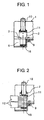
- Fig. 1 to Fig. 3 show a terminal arrangement provided with a box terminal device as a first embodiment according to the invention.
- the terminal arrangement illustrated in Fig. 1 to Fig. 3 comprises a frame 1 same as that shown in Fig. 7 to Fig. 9 with two exceptions, namely, in Fig. 1 to 3, a bottom plate of the frame 1 forming the box-like space 6 has a cylinder-like shallow recess 16 in its surface, and a wall standing upright from the bottom plate and defining a front abutment of the space 6 for the terminal fitting 2 has a rectangular shallow recess 17 (see Fig. 3) in the surface thereof.
- Structures of the terminal fitting 2 and the terminal strip 3 are the same as those in the known terminal arrangement of Figs. 7 to 9.
- the terminal strip 3 to which a stripped wire 12 is connected is attached to the frame 1.
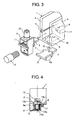
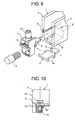
- Fig. 4 to Fig. 6 show a terminal arrangement provided as a terminal device for a terminal lug as a second embodiment according to the invention.
- the difference from the prior art of Fig. 7 to Fig. 9 is that the same frame 1 as that used in the first embodiment is employed and an attachment piece 18 of insulation material is provided in addition to this frame 1 having the recesses 16 and 17 therein.
- the attachment piece 18 is made of molded resin like the frame 1 itself and manufactured in a cube-like shape with its width and height fitting into the box-like space 6 in the frame 1.
- the attachment piece 18 has a cylinder-like recess 18a on the upper face thereof and a low column-like projection 18b (see Fig. 4) on the lower face thereof.
- the column-like projection 18b fits into the recess 16 on the bottom plate of the frame 1.
- a resilient claw 18c is provided which fits into the recess 17 on the surface of the wall standing from the bottom plate in the frame 1.
- the resilient claw 18c is formed as a flexible tongue-like piece extending substantially in parallel to the surface having the recess formed therein with a clearance provided between surroundings.
- An engagement piece is provided on the tongue-like piece to extend toward and engage with the recess, when the attachment piece is installed (see Fig. 5).
- three attachment pieces 18 are used as shown in Fig. 6. Of the three attachment pieces 18, respective two attachment pieces 18 for adjacent phases are coupled to each other by a U-shape coupling unit 19 provided connecting the adjacent insulation walls 4.
- the structure of a terminal strip 3' having a terminal screw 10 is the same as that in the prior art explained above with reference to Figs.10 to 12.
- the attachment piece 18 is first inserted into the box-like space 6 with the box terminal device being removed. At this time, the projection 18b is fitted into the recess 16 in the surface of the bottom plate of the frame 1. Then, the resilient claw 18c on the back of the attachment piece 18 is fitted into the recess 17 in the surface of the wall standing from the bottom plate. In this state, the attachment piece 18 is restrained from moving back and forth and moving up and down by the projection 18b and the resilient claw 18c, respectively, to be temporarily held in the frame 1.
- the terminal strip 3' with the terminal screw 10 detached is inserted into the grooves 5 to position the threaded hole in the terminal strip 3' for the terminal screw 10 over the cylinder-like recess 18a in the attachment piece 18.
- the terminal screw 10 is screwed into the terminal strip 3' to fit the threaded section of the screw 10 into the cylinder-like recess 18a in the attachment piece 18. This prevents the terminal strip 3' from slipping off the attachment piece 18.
- a cable 12 provided with a terminal lug 14 is connected to the terminal strip 3' in the same way as explained above for the case of Figs. 10 to 12.
- the upper face of the attachment piece 18 is recessed by providing a step 18d.
- the frame 1 for a box terminal device can be commonly used for a terminal device for a terminal lug to make it unnecessary to prepare an exclusive frame for each of the terminal devices. Therefore, even after an electromagnetic contactor has been installed, the connection system can be changed without replacing the main body of the contactor. Moreover, also in the manufacturing stage of the magnetic contactor, the number of kinds of frames are reduced to reduce manufacturing costs. Along with this, inventory control of the frames becomes easy. Furthermore, by making the attachment piece 18 temporarily held to the frame 1 with the resilient claw 18c and by making attachment pieces for multiphase terminals integrated with the coupling units 19, assembling work of the terminal device becomes easy.
- an electromagnetic contactor was shown as an example of electrical apparatus. The invention, however, can be applied to other kinds of electrical apparatus having terminal devices such as a molded-case circuit breaker and a terminal base.
Landscapes
- Connections Arranged To Contact A Plurality Of Conductors (AREA)
- Breakers (AREA)
- Connections By Means Of Piercing Elements, Nuts, Or Screws (AREA)
Abstract
Description
- Fig. 1
- is a vertical cross sectional view showing the structure of a terminal arrangement provided with a box terminal device as a first embodiment according to the invention;
- Fig. 2
- is a vertical cross sectional view showing a state in which a cable is connected to the box terminal device in Fig. 1;
- Fig. 3
- is an exploded perspective view of the terminal arrangement of Fig. 1;
- Fig.4
- is a vertical cross sectional view showing the structure of a terminal arrangement provided with a terminal device for a terminal lug as a second embodiment according to the invention;
- Fig. 5
- is a vertical cross sectional view showing a state in which a cable is connected to the terminal device for a terminal lug in Fig. 4;
- Fig. 6
- is an exploded perspective view of the terminal arrangement of Fig. 4;
- Fig. 7
- is a vertical cross sectional view showing the structure of an example of a prior art terminal arrangement with a box terminal device;
- Fig. 8
- is a vertical cross sectional view showing a state in which a cable is connected to the box terminal device in Fig. 7;
- Fig. 9
- is an exploded perspective view of the arrangement of Fig. 7;
- Fig. 10
- is a vertical cross sectional view showing the structure of an example of a prior art terminal arrangement with a terminal device for a terminal lug;
- Fig. 11
- is a vertical cross sectional view showing a state in which a cable is connected to the terminal device for a terminal lug in Fig. 10; and
- Fig. 12
- is an exploded perspective view the terminal arrangement of Fig. 10.
Claims (3)
- A terminal arrangement of electrical apparatus for connecting a cable to the apparatus, comprising:wherein the attachment piece (18) and the terminal strip (3') as a unit are replaceable by a box-shaped terminal fitting (2) mounted on a terminal strip (3) such that the terminal fitting (2), instead of said attachment piece (18), is accommodated in said box-like space (6) and its terminal strip (3) has lateral projections (3a) extending into said grooves (5).a frame (1) having a first and a second wall (4) of insulating material provided in parallel with each other, a bottom plate of insulating material provided between the first and the second wall, and a third wall standing on the bottom plate, such that a box-like space (6) is defined between the three walls and the bottom plate, the space being open at the side opposite to the third wall, wherein two grooves (5) opposing each other and extending from said open side toward said third wall are provided, one in each of the first and second walls (4), and a first recess (16) is provided in said bottom plate;an attachment piece (18) of insulating material having a box-like shape to fit into said box-like space (6) to be detachably accommodated therein and having a cylinder-like recess (18a) in a first face and a projection on a second face, opposite to said first face, the attachment piece (18) being positioned in said box-like space (6) such that its second face opposes said bottom plate and the projection engages said first recess (16) for preventing the attachment piece (18) from slipping off; anda terminal strip (3') having a terminal screw (10) for a terminal lug detachably mounted over said first face of the attachment piece in said box-like space (6) with lateral edges of the terminal strip (3') extending into and being guided by said grooves (5) and a screw section of the terminal screw (10) extending into said cylinder-like recess (18a) of the attachment piece (18) for preventing the terminal strip (3') from slipping off;
- The terminal arrangement of claim 1 wherein said third wall has a second recess (17) formed therein and the attachment piece (18) is provided with a resilient claw (18c) at the side facing the third wall, and the second recess (17) and the resilient claw (18c) are adapted to be detachably engaged with each other to thereby hold the attachment piece (18) in the frame (1).
- The terminal arrangement of claim 1 for connecting cables to a multiphase electrical apparatus, wherein said frame (1) comprises for each of the phases one set of said first, second and third walls and the bottom plate to define a respective one of a corresponding plurality of box-shaped spaces, and the attachment pieces (18), one for each phase, are coupled among each other by a coupling unit (19) connecting the first wall of one set to the second wall of an adjacent set.
Applications Claiming Priority (2)
| Application Number | Priority Date | Filing Date | Title |
|---|---|---|---|
| JP2004140733 | 2004-05-11 | ||
| JP2004140733A JP4341464B2 (en) | 2004-05-11 | 2004-05-11 | Terminal equipment for electrical equipment |
Publications (2)
| Publication Number | Publication Date |
|---|---|
| EP1596471A1 true EP1596471A1 (en) | 2005-11-16 |
| EP1596471B1 EP1596471B1 (en) | 2006-09-27 |
Family
ID=34935866
Family Applications (1)
| Application Number | Title | Priority Date | Filing Date |
|---|---|---|---|
| EP05009298A Expired - Fee Related EP1596471B1 (en) | 2004-05-11 | 2005-04-28 | Terminal arrangement of electrical apparatus |
Country Status (7)
| Country | Link |
|---|---|
| US (1) | US6981901B2 (en) |
| EP (1) | EP1596471B1 (en) |
| JP (1) | JP4341464B2 (en) |
| KR (1) | KR100910100B1 (en) |
| CN (1) | CN100568429C (en) |
| DE (1) | DE602005000149T2 (en) |
| TW (1) | TWI325667B (en) |
Cited By (10)
| Publication number | Priority date | Publication date | Assignee | Title |
|---|---|---|---|---|
| EP2019449A2 (en) | 2007-07-26 | 2009-01-28 | Abb Ag | Screw-clamp and method for manufacturing thereof |
| ES2339311A1 (en) * | 2007-04-03 | 2010-05-18 | Ls Industrial Systems Co., Ltd. | Modular terminal for molded case circuit breaker and molded case circuit breaker having the same |
| WO2010121727A1 (en) * | 2009-04-20 | 2010-10-28 | Phoenix Contact Gmbh & Co. Kg | Electric terminal |
| EP2302750A1 (en) * | 2008-07-16 | 2011-03-30 | Toyota Auto Body Co., Ltd. | Terminal installation structure for electrical junction box |
| WO2013186432A1 (en) * | 2012-06-11 | 2013-12-19 | Abb Oy | Electric current switching apparatus |
| US8882547B2 (en) | 2011-07-11 | 2014-11-11 | Panasonic Corporation | Screw terminal block and attachment plug including the same |
| US20150180139A1 (en) * | 2013-12-19 | 2015-06-25 | Siemens Industry, Inc. | Lug retention arrangement |
| WO2016077626A1 (en) * | 2014-11-13 | 2016-05-19 | Solarcity Corporation | Systems for backfeeding photovoltaic arrays through main breaker boxes |
| EP3125268A4 (en) * | 2014-03-26 | 2017-11-22 | Abb AS | Connection assembly for fuse base connection terminal |
| US9899169B2 (en) | 2012-06-11 | 2018-02-20 | Abb Oy | Electric current switching apparatus |
Families Citing this family (18)
| Publication number | Priority date | Publication date | Assignee | Title |
|---|---|---|---|---|
| CN101506921B (en) * | 2006-08-23 | 2013-06-05 | Abb技术有限公司 | Vacuum based diverter switch for tap changer |
| US7578711B2 (en) * | 2007-04-13 | 2009-08-25 | Siemens Energy & Automation, Inc. | Devices, systems, and method for coupling electrical conductors |
| JP5110384B2 (en) * | 2008-08-07 | 2012-12-26 | 住友電装株式会社 | connector |
| JP5468440B2 (en) * | 2010-03-30 | 2014-04-09 | 河村電器産業株式会社 | Terminal block |
| JP5196274B2 (en) * | 2010-05-20 | 2013-05-15 | 株式会社安川電機 | TERMINAL DEVICE, ELECTRONIC DEVICE, AND METHOD FOR MANUFACTURING ELECTRONIC DEVICE |
| CN104143703B (en) * | 2013-05-10 | 2017-02-15 | 町洋机电(中国)有限公司 | Welding type electric connector with same wire inlet and pin outlet direction |
| JP6260893B2 (en) * | 2013-10-04 | 2018-01-17 | パナソニックIpマネジメント株式会社 | Electromagnetic relay |
| CN104852192A (en) * | 2014-02-14 | 2015-08-19 | 欧姆龙株式会社 | Electronic device |
| CA2938881C (en) * | 2014-02-18 | 2021-08-24 | Labinal, Llc | Switching assembly and interconnect assembly therefor |
| JP6340726B2 (en) * | 2014-06-23 | 2018-06-13 | 株式会社ホンダロック | Part fastening structure |
| US9601841B2 (en) * | 2014-10-16 | 2017-03-21 | Hubbell Incorporated | Wire terminal assembly and adapter kit |
| US9299523B1 (en) * | 2014-12-12 | 2016-03-29 | Eaton Corporation | Switching device assembly and adapter assembly therefor |
| JP6428271B2 (en) * | 2015-01-07 | 2018-11-28 | 富士電機株式会社 | Power converter |
| CN104576215B (en) * | 2015-01-12 | 2017-01-11 | 厦门宏发开关设备有限公司 | Contactor |
| EP3379269B1 (en) * | 2017-03-24 | 2022-11-16 | TE Connectivity Solutions GmbH | Monitoring accessory for an electrical apparatus provided with a connection terminal |
| CN108321029B (en) * | 2017-12-30 | 2024-02-20 | 三友联众集团股份有限公司 | Relay with screw thread head |
| CN110086011B (en) * | 2019-04-19 | 2020-11-27 | 益风电缆有限公司 | Three-core cable terminal shaping device |
| CN115498447B (en) * | 2022-09-30 | 2023-09-15 | 苏州西门子电器有限公司 | Connecting terminal |
Citations (5)
| Publication number | Priority date | Publication date | Assignee | Title |
|---|---|---|---|---|
| US3888560A (en) * | 1974-02-13 | 1975-06-10 | Gen Electric | Electrical terminal configuration |
| US4136924A (en) * | 1977-12-07 | 1979-01-30 | Westinghouse Electric Corp. | Terminal connector |
| US5772479A (en) * | 1996-05-10 | 1998-06-30 | Fleege; Dennis William | Circuit breaker with terminal nut retainer |
| US6379196B1 (en) * | 2000-03-01 | 2002-04-30 | General Electric Company | Terminal connector for a circuit breaker |
| JP2002190331A (en) * | 2000-12-22 | 2002-07-05 | Fuji Electric Co Ltd | Box terminal of electrical apparatus |
Family Cites Families (8)
| Publication number | Priority date | Publication date | Assignee | Title |
|---|---|---|---|---|
| US3452317A (en) * | 1967-02-09 | 1969-06-24 | Hubbell Inc Harvey | Clamp-type terminal |
| JPS5412082U (en) | 1977-06-28 | 1979-01-26 | ||
| US4210379A (en) * | 1979-03-15 | 1980-07-01 | Amp Incorporated | Modular barrier block |
| JPH08167434A (en) * | 1994-10-11 | 1996-06-25 | Fuji Electric Co Ltd | Terminal device for electrical equipment |
| US5741153A (en) * | 1995-07-27 | 1998-04-21 | Ortronics, Inc. | Modular connectors including terminated rear connector designation for insulation displacement connectors |
| US6036542A (en) * | 1998-07-01 | 2000-03-14 | General Electric Company | Saddle assembly for a circuit breaker |
| JP2000251977A (en) * | 1999-02-26 | 2000-09-14 | Fujitsu Ltd | Power supply terminal |
| ES2199029B1 (en) * | 2001-09-07 | 2005-05-01 | Ge Power Controls Iberica, S.L. | RAPID CONNECTION SYSTEM OF ELECTRICAL OR ELECTRONIC DEVICES WITH INTERCHANGEABLE COMMON ELEMENTS. |
-
2004
- 2004-05-11 JP JP2004140733A patent/JP4341464B2/en not_active Expired - Fee Related
-
2005
- 2005-03-31 KR KR1020050026954A patent/KR100910100B1/en active IP Right Grant
- 2005-04-08 TW TW094111254A patent/TWI325667B/en not_active IP Right Cessation
- 2005-04-18 US US11/107,858 patent/US6981901B2/en active Active
- 2005-04-28 EP EP05009298A patent/EP1596471B1/en not_active Expired - Fee Related
- 2005-04-28 DE DE602005000149T patent/DE602005000149T2/en active Active
- 2005-05-11 CN CNB2005100691602A patent/CN100568429C/en not_active Expired - Fee Related
Patent Citations (5)
| Publication number | Priority date | Publication date | Assignee | Title |
|---|---|---|---|---|
| US3888560A (en) * | 1974-02-13 | 1975-06-10 | Gen Electric | Electrical terminal configuration |
| US4136924A (en) * | 1977-12-07 | 1979-01-30 | Westinghouse Electric Corp. | Terminal connector |
| US5772479A (en) * | 1996-05-10 | 1998-06-30 | Fleege; Dennis William | Circuit breaker with terminal nut retainer |
| US6379196B1 (en) * | 2000-03-01 | 2002-04-30 | General Electric Company | Terminal connector for a circuit breaker |
| JP2002190331A (en) * | 2000-12-22 | 2002-07-05 | Fuji Electric Co Ltd | Box terminal of electrical apparatus |
Non-Patent Citations (1)
| Title |
|---|
| PATENT ABSTRACTS OF JAPAN vol. 2002, no. 11 6 November 2002 (2002-11-06) * |
Cited By (17)
| Publication number | Priority date | Publication date | Assignee | Title |
|---|---|---|---|---|
| ES2339311A1 (en) * | 2007-04-03 | 2010-05-18 | Ls Industrial Systems Co., Ltd. | Modular terminal for molded case circuit breaker and molded case circuit breaker having the same |
| DE102007035016A1 (en) * | 2007-07-26 | 2009-01-29 | Abb Ag | Screw terminal and method for its manufacture |
| US7575486B2 (en) | 2007-07-26 | 2009-08-18 | Abb Ag | Screw connecting terminal and method for its production |
| EP2019449A3 (en) * | 2007-07-26 | 2009-12-16 | Abb Ag | Screw-clamp and method for manufacturing thereof |
| EP2019449A2 (en) | 2007-07-26 | 2009-01-28 | Abb Ag | Screw-clamp and method for manufacturing thereof |
| EP2302750A1 (en) * | 2008-07-16 | 2011-03-30 | Toyota Auto Body Co., Ltd. | Terminal installation structure for electrical junction box |
| EP2302750A4 (en) * | 2008-07-16 | 2012-04-04 | Toyota Auto Body Co Ltd | Terminal installation structure for electrical junction box |
| WO2010121727A1 (en) * | 2009-04-20 | 2010-10-28 | Phoenix Contact Gmbh & Co. Kg | Electric terminal |
| US8882547B2 (en) | 2011-07-11 | 2014-11-11 | Panasonic Corporation | Screw terminal block and attachment plug including the same |
| WO2013186432A1 (en) * | 2012-06-11 | 2013-12-19 | Abb Oy | Electric current switching apparatus |
| US9691558B2 (en) | 2012-06-11 | 2017-06-27 | Abb Oy | Electric current switching apparatus |
| US9899169B2 (en) | 2012-06-11 | 2018-02-20 | Abb Oy | Electric current switching apparatus |
| US20150180139A1 (en) * | 2013-12-19 | 2015-06-25 | Siemens Industry, Inc. | Lug retention arrangement |
| US9270033B2 (en) * | 2013-12-19 | 2016-02-23 | Siemens Industry, Inc. | Lug retention arrangement |
| EP3125268A4 (en) * | 2014-03-26 | 2017-11-22 | Abb AS | Connection assembly for fuse base connection terminal |
| WO2016077626A1 (en) * | 2014-11-13 | 2016-05-19 | Solarcity Corporation | Systems for backfeeding photovoltaic arrays through main breaker boxes |
| US10211610B2 (en) | 2014-11-13 | 2019-02-19 | Solarcity Corporation | Systems for backfeeding photovoltaic arrays through main breaker boxes |
Also Published As
| Publication number | Publication date |
|---|---|
| JP2005322554A (en) | 2005-11-17 |
| CN1697105A (en) | 2005-11-16 |
| US20050255757A1 (en) | 2005-11-17 |
| TW200607193A (en) | 2006-02-16 |
| EP1596471B1 (en) | 2006-09-27 |
| DE602005000149D1 (en) | 2006-11-09 |
| JP4341464B2 (en) | 2009-10-07 |
| KR100910100B1 (en) | 2009-07-30 |
| TWI325667B (en) | 2010-06-01 |
| CN100568429C (en) | 2009-12-09 |
| KR20060045066A (en) | 2006-05-16 |
| US6981901B2 (en) | 2006-01-03 |
| DE602005000149T2 (en) | 2007-10-25 |
Similar Documents
| Publication | Publication Date | Title |
|---|---|---|
| EP1596471B1 (en) | Terminal arrangement of electrical apparatus | |
| US7717720B2 (en) | Electric connection box | |
| US6894891B2 (en) | Smart junction box for automobile | |
| EP2432091B1 (en) | Bracket structure of electrical connection box | |
| US9553434B2 (en) | Electronic component assembly structure and electrical junction box | |
| US9942996B2 (en) | Electronic circuit unit | |
| JP4637730B2 (en) | holder | |
| CN109428293B (en) | Electrical junction box | |
| US7713070B2 (en) | Electric connection box | |
| JP2007213963A (en) | Terminal device of electric appliance | |
| EP2665129B1 (en) | Terminal platform block | |
| US8092237B2 (en) | Electrical connection bar and adapted connection device | |
| US7314376B2 (en) | Electric distribution box | |
| WO2017209204A1 (en) | Board unit | |
| EP3037304B1 (en) | Electrical junction box for vehicle | |
| JP4739967B2 (en) | Terminal block | |
| US20200168423A1 (en) | Attachment structure between cover and housing, and fusible link unit | |
| KR101531315B1 (en) | Fuse and fuse attachment structure | |
| US10874017B2 (en) | Board unit | |
| JP2007265954A (en) | Fuse and fuse connection structure | |
| US9974195B2 (en) | Electrical junction box | |
| JPH0620299Y2 (en) | Conductive connection device | |
| JPH1198649A (en) | Bus bar structure of electrical connection box | |
| JP2008086070A (en) | Electrical connection box | |
| JP2003142175A (en) | Terminal stand |
Legal Events
| Date | Code | Title | Description |
|---|---|---|---|
| PUAI | Public reference made under article 153(3) epc to a published international application that has entered the european phase |
Free format text: ORIGINAL CODE: 0009012 |
|
| AK | Designated contracting states |
Kind code of ref document: A1 Designated state(s): AT BE BG CH CY CZ DE DK EE ES FI FR GB GR HU IE IS IT LI LT LU MC NL PL PT RO SE SI SK TR |
|
| AX | Request for extension of the european patent |
Extension state: AL BA HR LV MK YU |
|
| 17P | Request for examination filed |
Effective date: 20051201 |
|
| GRAP | Despatch of communication of intention to grant a patent |
Free format text: ORIGINAL CODE: EPIDOSNIGR1 |
|
| RIN1 | Information on inventor provided before grant (corrected) |
Inventor name: TAKAYA, KOUETSU,C/O FUJI ELECTRIC FA COMPONENTS |
|
| GRAS | Grant fee paid |
Free format text: ORIGINAL CODE: EPIDOSNIGR3 |
|
| AKX | Designation fees paid |
Designated state(s): DE FR IT |
|
| GRAA | (expected) grant |
Free format text: ORIGINAL CODE: 0009210 |
|
| AK | Designated contracting states |
Kind code of ref document: B1 Designated state(s): DE FR IT |
|
| PG25 | Lapsed in a contracting state [announced via postgrant information from national office to epo] |
Ref country code: IT Free format text: LAPSE BECAUSE OF FAILURE TO SUBMIT A TRANSLATION OF THE DESCRIPTION OR TO PAY THE FEE WITHIN THE PRESCRIBED TIME-LIMIT;WARNING: LAPSES OF ITALIAN PATENTS WITH EFFECTIVE DATE BEFORE 2007 MAY HAVE OCCURRED AT ANY TIME BEFORE 2007. THE CORRECT EFFECTIVE DATE MAY BE DIFFERENT FROM THE ONE RECORDED. Effective date: 20060927 |
|
| REF | Corresponds to: |
Ref document number: 602005000149 Country of ref document: DE Date of ref document: 20061109 Kind code of ref document: P |
|
| ET | Fr: translation filed | ||
| PLBE | No opposition filed within time limit |
Free format text: ORIGINAL CODE: 0009261 |
|
| STAA | Information on the status of an ep patent application or granted ep patent |
Free format text: STATUS: NO OPPOSITION FILED WITHIN TIME LIMIT |
|
| 26N | No opposition filed |
Effective date: 20070628 |
|
| PGRI | Patent reinstated in contracting state [announced from national office to epo] |
Ref country code: IT Effective date: 20090601 |
|
| REG | Reference to a national code |
Ref country code: FR Ref legal event code: TP |
|
| PGFP | Annual fee paid to national office [announced via postgrant information from national office to epo] |
Ref country code: IT Payment date: 20130419 Year of fee payment: 9 |
|
| PG25 | Lapsed in a contracting state [announced via postgrant information from national office to epo] |
Ref country code: IT Free format text: LAPSE BECAUSE OF FAILURE TO SUBMIT A TRANSLATION OF THE DESCRIPTION OR TO PAY THE FEE WITHIN THE PRESCRIBED TIME-LIMIT Effective date: 20140428 |
|
| REG | Reference to a national code |
Ref country code: FR Ref legal event code: PLFP Year of fee payment: 12 |
|
| REG | Reference to a national code |
Ref country code: FR Ref legal event code: PLFP Year of fee payment: 13 |
|
| REG | Reference to a national code |
Ref country code: FR Ref legal event code: PLFP Year of fee payment: 14 |
|
| PGFP | Annual fee paid to national office [announced via postgrant information from national office to epo] |
Ref country code: FR Payment date: 20200312 Year of fee payment: 16 |
|
| PGFP | Annual fee paid to national office [announced via postgrant information from national office to epo] |
Ref country code: DE Payment date: 20200415 Year of fee payment: 16 |
|
| REG | Reference to a national code |
Ref country code: DE Ref legal event code: R119 Ref document number: 602005000149 Country of ref document: DE |
|
| PG25 | Lapsed in a contracting state [announced via postgrant information from national office to epo] |
Ref country code: FR Free format text: LAPSE BECAUSE OF NON-PAYMENT OF DUE FEES Effective date: 20210430 Ref country code: DE Free format text: LAPSE BECAUSE OF NON-PAYMENT OF DUE FEES Effective date: 20211103 |