EP1513033A1 - Method and device for controlling a controlled variable - Google Patents
Method and device for controlling a controlled variable Download PDFInfo
- Publication number
- EP1513033A1 EP1513033A1 EP03020210A EP03020210A EP1513033A1 EP 1513033 A1 EP1513033 A1 EP 1513033A1 EP 03020210 A EP03020210 A EP 03020210A EP 03020210 A EP03020210 A EP 03020210A EP 1513033 A1 EP1513033 A1 EP 1513033A1
- Authority
- EP
- European Patent Office
- Prior art keywords
- signal
- value
- output signal
- component
- switching
- Prior art date
- Legal status (The legal status is an assumption and is not a legal conclusion. Google has not performed a legal analysis and makes no representation as to the accuracy of the status listed.)
- Granted
Links
Images


Classifications
-
- G—PHYSICS
- G05—CONTROLLING; REGULATING
- G05B—CONTROL OR REGULATING SYSTEMS IN GENERAL; FUNCTIONAL ELEMENTS OF SUCH SYSTEMS; MONITORING OR TESTING ARRANGEMENTS FOR SUCH SYSTEMS OR ELEMENTS
- G05B5/00—Anti-hunting arrangements
- G05B5/01—Anti-hunting arrangements electric
-
- G—PHYSICS
- G05—CONTROLLING; REGULATING
- G05B—CONTROL OR REGULATING SYSTEMS IN GENERAL; FUNCTIONAL ELEMENTS OF SUCH SYSTEMS; MONITORING OR TESTING ARRANGEMENTS FOR SUCH SYSTEMS OR ELEMENTS
- G05B11/00—Automatic controllers
- G05B11/01—Automatic controllers electric
- G05B11/36—Automatic controllers electric with provision for obtaining particular characteristics, e.g. proportional, integral, differential
- G05B11/42—Automatic controllers electric with provision for obtaining particular characteristics, e.g. proportional, integral, differential for obtaining a characteristic which is both proportional and time-dependent, e.g. P.I., P.I.D.
Abstract
Description
Die Erfindung betrifft ein Verfahren und eine Vorrichtung zur Regelung einer Regelgröße, die über eine Stellgröße veränderbar ist, die in Abhängigkeit eines Sollwertes und eines Istwertes für die Regelgröße mit einem Regelalgorithmus berechnet wird, der einen Integralanteil und einen weiteren Anteil aufweist, wobei die Stellgröße, der Integralanteil und der weitere Anteil mit dem Regelalgorithmus berechnet werden.The invention relates to a method and a device for Control of a controlled variable via a manipulated variable is changeable, depending on a setpoint and an actual value for the controlled variable with a control algorithm is calculated, one integral part and another Share, wherein the manipulated variable, the integral component and the further portion can be calculated with the control algorithm.
Bei einem Prozess, bei dem es auf genaue Einhaltung von Prozessbedingungen ankommt, ist es erforderlich, den Prozess zu beobachten, Abweichungen von einem geforderten Verhalten zu registrieren und in geeigneter Art und Weise auf diese Abweichungen zu reagieren. Die Reaktion soll dazu führen, dass ein gefordertes Regel-Verhalten sich wieder einstellt. Zur Beobachtung des Prozesses müssen Signale gemessen werden, die den Prozess beschreiben bzw. Informationen über herrschende Zustände liefern wie z. B. Temperatur, Druck, Stoffgröße, Volumenstrom, ... Der Vergleich eines gemessenen mit einem geforderten Zustand, sowie die daraus vorzunehmenden Eingriffe in den Prozess können entweder von Menschen oder von Geräten vorgenommen werden. In beiden Fällen spricht man von Regelung. Eine Regelung ist gekennzeichnet durch die Schritte: Messen, Vergleichen und Regeln. Ein Regelkreis dient dazu, den vorgegebenen Wert einer physikalischen Größe als Regelgröße einzustellen. Hierbei werden der aktuelle Wert der physikalischen Größe und der vorgegebene Wert gemessen und verglichen. Eine Differenz dieser beiden Werte muss durch entsprechende Maßnahmen beseitigt werden. Eine Größe, die zu diesem Zweck geändert werden muss und einen Einfluss auf den Wert der physikalischen Größe hat, wird als Stellgröße bezeichnet. Ein Mittel, das den Vergleich zwischen dem Istwert und dem Sollwert der physikalischen Größe zur Gewinnung einer Regelabweichung durchführt und einen Wert für die Stellgröße ermittelt, wird als Regler bezeichnet. In a process where there is strict adherence to Process conditions arrives, it is necessary to complete the process to observe deviations from a required behavior to register and in an appropriate manner to this Deviations to respond. The reaction should cause that a required rule behavior is restored. To observe the process, signals must be measured describing the process or information about provide prevailing conditions such. Temperature, pressure, Substance size, volume flow, ... The comparison of a measured with a required condition, as well as the resulting Any intervention in the process can be carried out either by People or equipment. In both Cases one speaks of regulation. A regulation is characterized by the steps: measuring, comparing and Regulate. A control loop serves to set the given value to set a physical variable as a controlled variable. Here, the current value of the physical quantity and the given value was measured and compared. A difference These two values must be taken by appropriate measures be eliminated. A size that has been changed for this purpose must be and have an impact on the value of physical size has, is called the manipulated variable. One Means comparing the actual value and the Setpoint of the physical quantity for obtaining a Control deviation and a value for the manipulated variable determined, is called controller.
Bekannt sind so genannte PID- bzw. PI-Regler. Mit PID- bzw. PI-Reglern wird das zeitliche Verhalten einer Abweichung zwischen dem aktuellen und gewünschten Wert der physikalischen Größe in geeigneter Weise durch Vorgabe von drei bzw. zwei Regel-Parametern minimiert. Eine umfassende Beschreibung eines PID-Reglers ist z. B. in dem Lehrbuch "Regelungstechnik-ein praxisorientiertes Lehrbuch", Verlag Harri Deutsch, Frankfurt am Main, ISBN 3-8171-1653-5 beschrieben.Known are so-called PID or PI controllers. With PID or PI controllers become the temporal behavior of a deviation between the current and desired value of physical size in a suitable manner by specifying minimizes three or two rule parameters. A comprehensive Description of a PID controller is z. In the textbook "Control engineering-a practice-oriented textbook", publisher Harri German, Frankfurt am Main, ISBN 3-8171-1653-5 described.
Für eine Regelsituation, bei der der PID- bzw. PI-Regler einen Wert für die Stellgröße errechnet, der größer als der maximale, einstellbare wirksame Wert der Stellgröße ist, können Probleme auftauchen. Wenn eine Regelabweichung vorhanden ist, kann der Wert des Integralanteils durch fortlaufende Integration weiter anwachsen. Wenn die Regelabweichung nun ein anderes Vorzeichen annimmt, muss der Regel-Algorithmus des PID- bzw. PI-Reglers zu dem Ergebnis führen, dass die Stellgröße sich von ihrem maximalen einstellbaren Wert entfernt. Da jedoch der Wert des Integralanteils möglicher Weise sehr hoch ist, könnte der PID- bzw. PI-Regler einer Störung nicht sofort entgegenwirken. Hierdurch können Grenzwerte vorübergehend überschritten werden. Ein Beispiel hierfür wäre der Einsatz eines solchen Reglers in einer Pumpgrenzregelung eines Verdichters. Die Regelgröße, die z. B. ein saugseitiger Volumenstrom sein kann, kann größer als der durch eine Regellinie vorgegebene Sollwert werden. Der Ausgang des PID- bzw. PI-Reglers führt zu einer vollständigen Schließung eines Regelventils. Da jedoch der PID- bzw. PI-Regler noch eine positive Regelabweichung erfasst, vergrößert sich der Integralanteil des PID- bzw. PI-Reglers. Wenn nun die Regelgröße den durch die Regellinie vorgegebenen Sollwert unterschreitet, muss das Regelventil unmittelbar öffnen. Da sich der Wert des Integralanteils des PID- bzw. PI-Reglers durch langen Betrieb im Bereich positiver Regelabweichungen erhöht hat, geschieht dies nicht. Die Regelung zeigt erst dann eine Wirkung, wenn der negative Wert des Proportionalanteils die Differenz zwischen diesem Wert und einer Ansprechschwelle des Stellelements erreicht. Es besteht hierbei die Gefahr, dass die Pumpgrenze im Falle einer Pumpgrenzregelung überschritten werden könnte.For a control situation in which the PID or PI controller calculates a value for the manipulated variable that is greater than the maximum, adjustable effective value of the manipulated variable is, problems can arise. If a control deviation is present, the value of the integral part by continuous integration continues to grow. If the Now the deviation assumes a different sign, the Rule algorithm of the PID or PI controller for the result cause the manipulated variable to differ from its maximum adjustable value removed. However, since the value of Integral part is possibly very high, the PID or PI controller of a fault not immediately counteract. This allows limits to be temporary be crossed, be exceeded, be passed. An example of this would be the use of such a regulator in a surge limit control of a Compressor. The controlled variable z. B. a suction side Volume flow can be greater than that by a Rule line predetermined setpoint. The output of the PID or PI controller leads to a complete closure of a Control valve. However, since the PID or PI controller is still a recorded positive control deviation, the increases Integral part of the PID or PI controller. If now the Controlled variable the setpoint given by the control line below, the control valve must open immediately. There the value of the integral part of the PID or PI controller due to long operation in the range of positive control deviations has increased, this does not happen. The regulation shows only then an effect, if the negative value of the Proportional share the difference between this value and reached a threshold of the control element. It exists here the danger that the surge limit in case of Pipe limit control could be exceeded.
Die Struktur des Reglerbausteins vom Kompaktregler ABB "Protronic PS2" zeigt das vorgenannte Verhalten. Hierbei wird aus einer Regelabweichung mit der Multiplikation einer Konstanten KP bzw. Division mit einer Konstanten XP der Proportionalanteil P gebildet. Der Proportionalanteil P wird zum Ausgangswert des Integralanteilwerts I addiert und bildet somit den Wert Yv. Die wirksame Stellgröße wird gebildet indem der Wert Yv durch eine Minimum- bzw. Maximumbegrenzung begrenzt wird.The structure of the controller module of the compact controller ABB "Protronic PS2" shows the aforementioned behavior. In this case, the proportional component P is formed from a control deviation with the multiplication of a constant K P or division with a constant X P. The proportional component P is added to the output value of the integral component value I and thus forms the value Y v . The effective manipulated variable is formed by the value Y v is limited by a minimum or maximum limit.
Um das Anwachsen des Integralanteils bei Erreichen der Grenze des Stellbereichs zu verhindern, wird ein internes Rückführungssignal IR gebildet. Die Rückführung IR wird aus der Differenz des wirksamen Stellsignals Y und dem Proportionalanteil P gebildet. In jedem Integrationsschritt wird zu diesem Wert ein Integral-Inkremet e*ΔT/TN addiert, wobei e die Regelabweichung, ΔT eine Zykluszeit und TN eine Nachstellzeit eines Integrators darstellen. Ist der Wert des wirksamen Stellsignals Y gleich dem vom Regelalgorithmus ermittelten Wert für das Stellsignal vor dem Minimum-Maximum-Begrenzer Yv, wächst oder fällt die Rückführung IR nicht mehr und bleibt einen Schritt vor dem Begrenzungswert stehen.In order to prevent the increase of the integral component upon reaching the limit of the setting range, an internal feedback signal I R is formed. The feedback I R is formed from the difference between the effective control signal Y and the proportional component P. In each integration step, an integral increment e * ΔT / T N is added to this value, where e represents the control deviation, ΔT a cycle time and T N an integral time of an integrator. If the value of the effective actuating signal Y is equal to the value determined by the control algorithm for the actuating signal before the minimum-maximum limiter Y v , the feedback I R no longer grows or falls and remains one step before the limiting value.
Bei einem weiteren Anwachsen der Regelabweichung e wird der Wert des Proportionalanteils P größer und somit wird der Rückführwert IR und der Ausgangswert des Integrators kleiner. Bei einem erneuten Sinken der Regelabweichung e muss der Wert des Integralanteils I wieder erhöht werden, damit der Wert Yv weiterhin begrenzt wird. Die Erhöhung des Wertes des Integralanteils I ist lediglich mit einer maximalen Geschwindigkeit möglich, die begrenzt ist. Der maximale Wert der Geschwindigkeit für die Änderung des Integralanteils I liegt bei e/TN . Wird dieser Wert überschritten, so entfernt sich der Ausgang trotz weiterhin positiver Regelabweichung e von der Grenze. Da der Reglerausgang Y hierbei scheinbar von der Ableitung der Regelabweichung e beeinflusst wird, spricht man hier von einem pseudo differenzierendem Verhalten.As the control deviation e increases further, the value of the proportional component P becomes greater, and thus the feedback value I R and the output value of the integrator become smaller. If the control deviation e drops again, the value of the integral component I must be increased again so that the value Y v is still limited. The increase of the value of the integral component I is only possible with a maximum speed which is limited. The maximum value of the velocity for the change in the integral component I is e / T N. If this value is exceeded, the output moves away from the limit despite the continued positive control deviation e. Since the controller output Y is apparently influenced by the derivation of the control deviation e, this is called a pseudo-differentiating behavior.
Im Falle einer Begrenzungsregelung kann dies von Vorteil sein, weil damit vor Erreichen eines Grenzsollwertes eine Reaktion des Reglers bewirkt wird und ein Überschreiten des Grenzsollwertes verhindert oder verringert wird. Jedoch führt dieses Verfahren weit ab des Grenzwertes zu einem Verhalten, das unerwünscht ist, weil ein Stellelement hierbei unnötige Reaktionen zeigen könnte. Im Falle einer Pumpgrenzregelung könnte z. B. ein Regelventil bei einer Änderung des Volumenstroms oder bei einer Änderung der Drücke öffnen, obwohl noch ein ausreichender Abstand von der Regelkennlinie vorhanden ist.In the case of a limitation scheme, this can be an advantage be because so before reaching a limit setpoint one Reaction of the controller is effected and exceeding the Limit setpoint is prevented or reduced. However, leads this method far from the limit to behavior, this is undesirable because an actuator is unnecessary in this case Could show reactions. In the case of a surge limit control could z. B. a control valve at a change of Volume flow or when the pressures change, although still a sufficient distance from the control characteristic is available.
Dieses Problem könnte durch Anhalten der fortlaufenden Integrierung des Integralanteils des PID- bzw. PI-Reglers beim Überschreiten einer Begrenzung gelöst werden.This problem could be stopped by continuing Integration of the integral part of the PID or PI controller when a limit is exceeded.
Diese Lösung hat aber verschiedene Nachteile. Der Wert des gespeicherten Integralanteils ist abhängig von zeitlich vorangegangenen Einstellungen. Nähert sich der Ausgang des Reglers der Grenze mit geringer Regelabweichung und demnach kleinerem Wert des Proportionalanteils, so ist der gespeicherte Wert des Integralanteils höher, als wenn dies mit hoher Regelabweichung geschieht. Die Begrenzung könnte für den letzteren Fall wieder unterschritten werden, wenn die Regelabweichung wieder verringert wird. Ein Stellelement wie z. B. ein Regelventil würde trotz vorhandener positiver Regelabweichung vorübergehend öffnen. But this solution has several disadvantages. The value of stored integral portion is dependent on time previous settings. Approaching the output of the Regulator of the limit with low deviation and accordingly smaller value of the proportional component, so is the stored value of the integral component higher than if this happens with high deviation. The limit could be for the latter case fall below again, if the Control deviation is reduced again. An actuator like z. B. a control valve would despite existing positive Temporarily open the system deviation.
Ein weiterer Nachteil ist, dass ein Regler mit einem Reglerbaustein ausgestattet sein muss, der die Überschreitung der Begrenzung erkennt. Ein weiteres Problem tritt auf, wenn während des Betriebes an der Begrenzung die obere Grenze für die Regelgröße verkleinert oder die untere Grenze vergrößert wird. Es kann hierbei geschehen, dass im Integralanteil ein Wert gespeichert wird, der auch bei verschwindendem Proportionalanteil nicht zu einem Überschreiten der Grenze führt. Eine Veränderung der Grenzen im Betrieb führt demnach zu Störungen und diese sollten unterbleiben.Another disadvantage is that a regulator with a Controller module must be equipped, the exceeding recognizes the limitation. Another problem occurs when during operation at the limit the upper limit for the control variable is reduced or the lower limit is increased becomes. It can happen here that in the integral part Value is saved, even if disappearing Proportional component not to exceed the limit leads. A change in the limits in operation leads accordingly to disturbances and these should be avoided.
Für anspruchsvolle Regelaufgaben wie z. B. die Pumpgrenzregelung eines Verdichters ist diese Methode kaum geeignet.For demanding control tasks such. B. the Pipe limit control of a compressor, this method is hardly suitable.
Die Aufgabe der vorliegenden Erfindung ist es, ein Verfahren, und eine Vorrichtung zur Regelung einer Regelgröße, die über eine Stellgröße veränderbar ist und in Abhängigkeit eines Sollwertes mit einem Regelalgorithmus berechnet wird, anzugeben, das ein verbessertes Regelverhalten zeigt.The object of the present invention is to provide a method and a device for controlling a controlled variable, the a manipulated variable is variable and depending on a Setpoint is calculated with a control algorithm, indicate that shows improved control behavior.
Die auf das Verfahren hin gerichtete Aufgabe wird gelöst durch ein Verfahren zur Regelung einer Regelgröße, die über eine Stellgröße veränderbar ist, die in Abhängigkeit eines Sollwertes und eines Istwertes für die Regelgröße mit einem Regelalgorithmus berechnet wird, der einen Integralanteil und einen weiteren Anteil aufweist, wobei die Stellgröße, der Integralanteil und der weitere Anteil mit dem Regelalgorithmus berechnet werden, wobei der Wert der Stellgröße zuerst mit dem Regelalgorithmus berechnet wird und nach einem Minimum-Maximum-Begrenzer begrenzt und an den Regelalgorithmus zurückgemeldet wird, wobei eine Änderung des weiteren Anteils vernachlässigt wird, wenn folgende Bedingungen eintreten:
- der mit dem Regelalgorithmus berechnete Wert für die Stellgröße ist größer als der Wert, der nach dem Minimum-Maximum-Begrenzer begrenzt wird und
- eine Regelabweichung, die aus der Differenz zwischen dem Sollwert und der Regelgröße ermittelt wird, ist größer oder gleich einem vorgebbaren Grenzwert Xw,positiv oder
- der mit dem Regelalgorithmus berechnete Wert für die Stellgröße ist kleiner als der Wert, der nach dem Minimum-Maximum-Begrenzer begrenzt wird und
- die Regelabweichung ist kleiner oder gleich einem vorgebbaren Grenzwert Xw,negativ.
- the value for the manipulated variable calculated with the control algorithm is greater than the value that is limited to the minimum-maximum limiter and
- a control deviation, which is determined from the difference between the setpoint and the control variable is greater than or equal to a predetermined limit value X w, positive or
- the value for the manipulated variable calculated using the control algorithm is less than the value that is limited to the minimum-maximum limiter and
- the control deviation is less than or equal to a predefinable limit value X w, negative .
Das Umschalten auf dieses neue Verhalten wird als Umschaltlogik bezeichnet. Durch dieses neue Verfahren ist es möglich, dass der Wert des Integralanteils eines Reglers nicht fortlaufend erhöht wird. Ein weiterer Vorteil dieses Verfahrens ist, dass bei aktiver Begrenzung ein reproduzierbares Verhalten entsteht. Darüber hinaus ist bei aktiver Begrenzung eine Änderung der Grenzwerte im Betrieb möglich.Switching to this new behavior is called Switching logic called. It's through this new process possible that the value of the integral part of a regulator is not continuously increased. Another advantage of this Method is that with active limitation on reproducible behavior arises. In addition, at active limit a change of the limit values during operation possible.
Zweckmäßigerweise ist der weitere Anteil ein Proportionalanteil.Conveniently, the further portion is a Proportional share.
In einer vorteilhaften Weitergestaltung wird das Verfahren für ein Regelalgorithmus eingesetzt, der einen Differentialanteil aufweist und dieser Differentialanteil zu dem Proportionalanteil addiert wird. Dadurch ist es möglich, die Genauigkeit der Regelung zu erhöhen.In an advantageous further development, the method used for a control algorithm that has a Differential part has and this differential proportion to is added to the proportional component. This makes it possible to increase the accuracy of the scheme.
In einer weiteren vorteilhaften Weitergestaltung wird der weitere Anteil vernachlässigt, wenn folgende Bedingung zusätzlich eintritt:
- Signal wurde nach oben begrenzt und
- eine Änderung der Regelabweichung e ist größer als ein vorgebbarer Grenzwert Δ Xw,positiv oder
- Signal wurde nach unten begrenzt und
- eine Änderung der Regelabweichung e ist kleiner als ein vorgebbarer Grenzwert Δ Xw,negativ.
- Signal was limited to the top and
- a change in the control deviation e is greater than a predefinable limit ΔX w, positive or
- Signal was limited down and
- a change in the control deviation e is smaller than a predefinable limit ΔX w, negative .
Hierdurch ist es möglich, ein Signalrauschen der Regelabweichung zu berücksichtigen.This makes it possible, a signal noise of To take into account control deviation.
In einer weiteren vorteilhaften Ausgestaltung können Änderungen des Sollwertes wahlweise zur Berechnung des Differentialanteils berücksichtigt werden.In a further advantageous embodiment can Changes to the setpoint optionally for calculating the Differential component are taken into account.
Zweckmäßigerweise wird zur Verbesserung des Zeitverhaltens des Reglers der Differentialanteil mit einer einstellbaren Zeitkonstanten gefiltert.Conveniently, to improve the timing of the regulator of the differential component with an adjustable Time constants filtered.
Zweckmäßigerweise wird das Verfahren für den Betrieb eines Verdichters verwendet.Conveniently, the method for the operation of a Compressor used.
Die auf die Vorrichtung hin gerichtete Aufgabe wird gelöst durch eine Vorrichtung zur Regelung einer Regelgröße, die über eine Stellgröße veränderbar ist, mit einem Subtrahier-Baustein zur Berechnung einer Regelabweichung durch Subtrahieren eines Sollwertes der Regelgröße von einem Istwertes der Regelgröße, einem Integral-Inkrement-Baustein zum Berechnen eines Integral-Inkrement-Anteils für die Stellgröße als Ausgangssignal aufgrund der Regelabweichung, einem weiteren Baustein zum Berechnen eines weiteren Anteils für die Stellgröße als Ausgangssignal aufgrund der Regelabweichung, wobei die Vorrichtung folgende Bausteine umfasst:The task directed towards the device is solved by a device for controlling a controlled variable, the is variable via a manipulated variable, with a subtracting device to calculate a control deviation by Subtract a setpoint of the controlled variable from one Actual value of the controlled variable, an integral increment block for calculating an integral increment fraction for the Control value as output signal due to the control deviation, another building block for calculating a further share for the manipulated variable as an output signal due to Control deviation, wherein the device has the following components includes:
Einen Umschalt-Additions-Baustein, der einen ersten Eingang
für das Ausgangssignal des weiteren Bausteins,
einen zweiten Eingang für das Ausgangssignal des Integral-Inkrement-Bausteins,
einen dritten Eingang für ein Schaltsignal und
einen vierten Eingang für ein Signal aus einem Minimum-Maximum-Begrenzer,
der zur Begrenzung des Wertes für die
Stellgröße auf einen voreingestellten Wert ausgebildet ist,
wobei der Umschalt-Additions-Baustein zum Berechnen eines
Wertes für die Stellgröße als Ausgangssignal aufgrund des
weiteren Bausteins, dem Ausgangssignal des Integral-Inkrement-Baustein
und des Signals aus dem Minimum-Maximum-Begrenzers
ausgebildet ist, wobei der Umschalt-Additions-Baustein
zwischen einem ersten Zustand, bei dem das
Ausgangssignal des weiteren Bausteins zur Berechnung der
Stellgröße addiert wird und einem zweiten Zustand, bei dem
das Ausgangssignal des weiteren Bausteins geblockt wird,
umschaltbar ist, und einen Schalt-Baustein zum Erzeugen des
Schaltsignals für den Umschalt-Additions-Bausteins, wobei der
Schalt-Baustein derart ausgebildet ist, dass ein Schaltsignal
zum Umschalten in den zweiten Zustand an den Umschalt-Additions-Baustein
gesendet wird, wenn der Wert der
Stellgröße größer als der nach dem Minimum-Maximum-Begrenzer
voreingestellten Wert ist und die Regelabweichung größer oder
gleich einem vorgebbaren Grenzwert Xw,positiv ist oder wenn der
Wert der Stellgröße kleiner als der nach dem Minimum-Maximum-Begrenzer
voreingestellte Wert ist und die Regelabweichung
kleiner oder gleich einem vorgebbaren Grenzwert Xw,negativ ist.
Die Vorteile ergeben sich entsprechend der Beschreibung zur
Lösung des Verfahrens.A toggle addition module that provides a first input to the output of the further device,
a second input for the output signal of the integral increment module,
a third input for a switching signal and
a fourth input for a signal from a minimum-maximum limiter, which is designed to limit the value for the manipulated variable to a preset value, wherein the switching-addition module for calculating a value for the manipulated variable as an output signal due to the further block, is formed of the output signal of the integral increment block and the signal from the minimum-maximum limiter, wherein the switching-addition module between a first state in which the output signal of the further block for calculating the manipulated variable is added and a second state in which the output signal of the further module is blocked, can be switched over, and a switching component for generating the switching signal for the switching-addition component, wherein the switching component is designed such that a switching signal for switching to the second state the changeover addition block is sent when the value of the manipulated variable is greater it is the value preset after the minimum-maximum limiter and the control deviation is greater than or equal to a predefinable limit value X w, positive or if the value of the manipulated variable is smaller than the value preset after the minimum-maximum limiter and the control deviation is smaller or equal to a predeterminable limit value X w, is negative . The advantages arise according to the description of the solution of the method.
In einer vorteilhaften Weitergestaltung umfasst der Umschalt-Additions-Baustein einen Umschalt-Baustein und einen Additions-Baustein.In an advantageous further embodiment, the switching-addition module comprises a switching module and a Additions block.
Zweckmäßigerweise wird das Ausgangssignals des weiteren Bausteins und das Signal aus dem Minimum-Maximum-Begrenzer zusammengefasst und an den Umschalt-Baustein weitergeführt, und das Signal aus dem Minimum-Maximum-Begrenzer ebenfalls an den Umschalt-Baustein weitergeführt und der Umschalt-Baustein ist derart ausgebildet, dass zwischen einem ersten Zustand, bei dem die Summe des Signals durchgeleitet wird und einem zweiten Zustand, bei dem nur das Signal nach dem Minimum-Maximum-Begrenzer vorliegt, umschaltbar ist. Conveniently, the output signal of the other Block and the signal from the minimum-maximum limiter summarized and continued to the switching module, and the signal from the minimum-maximum limiter also on the switching module continued and the switching module is designed such that between a first state, in which the sum of the signal is passed through and one second state, in which only the signal after the minimum-maximum limiter is present, is switchable.
Zweckmäßigerweise wird der Additions-Baustein, der einen ersten Eingang für das Ausgangssignal des Umschalt-Bausteins und einen zweiten Eingang für das Ausgangssignal des Integral-Inkrement-Bausteins aufweist, derart ausgebildet, dass das Ausgangssignal des Umschalt-Bausteins und das Ausgangssignal des Integral-Inkrement-Bausteins zu einem Ausgangssignal addiert werden.Conveniently, the addition module, the one first input for the output signal of the switching module and a second input for the output signal of Integral increment module has, designed in such a way that the output of the switching block and the Output signal of the integral increment block to a Output signal are added.
In einer alternativen Ausführungsform wird der Umschalt-Baustein derart ausgebildet, dass der Umschalt-Baustein einen Eingang für ein den Wert Null aufweisendes Signal sowie zwischen einem ersten Zustand, bei dem das Ausgangssignal des weiteren Bausteins als Ausgangssignal durchgeleitet wird und einem zweiten Zustand, bei dem das den Wert Null aufweisende Signal durchgeleitet wird, umschaltbar ist.In an alternative embodiment, the switching module formed such that the switching block a Input for a zero value signal as well between a first state in which the output signal of the another block is passed as an output signal and a second state where the value is zero Signal is passed, is switchable.
Zweckmäßigerweise weist der Additions-Baustein einen weiteren Eingang auf, an dem das Signal aus dem Minimum-Maximum-Begrenzer anliegt.Conveniently, the addition module has another Input on to which the signal from the minimum-maximum limiter is applied.
Zweckmäßigerweise umfasst der weitere Baustein einen Proportionalanteil-Baustein und einen Differentialanteil-Baustein. Dadurch wird die Genauigkeit der Regelung erhöht.Conveniently, the further module comprises a Proportional component and a differential component. This increases the accuracy of the control.
In einer weiteren vorteilhaften Weitergestaltung wird der Differentialanteil-Baustein derart ausgebildet, dass zwischen einem ersten Zustand, bei dem die Änderung des Sollwertes durchgeleitet wird und einem zweiten Zustand, bei dem nur die Regelabweichung weitergeleitet wird, umgeschaltet wird. Die Genauigkeit der Regelung wird dadurch erhöht.In a further advantageous embodiment of the Differential component block designed such that between a first state in which the change of the setpoint is passed through and a second state in which only the Control deviation is forwarded, is switched. The Accuracy of the control is thereby increased.
In einer weiteren vorteilhaften Weitergestaltung weist der Differentialanteil-Baustein einen Verzögerungs-Baustein zum Berechnen des Differentialanteils auf. Dadurch wird die Genauigkeit der Regelung erhöht. In a further advantageous embodiment, the Differential component block a delay block for Calculate the differential component. This will be the Accuracy of the control increased.
Zweckmäßigerweise wird ein erster Zwischenspeicher-Baustein zwischen dem Minimum-Maximum-Begrenzer und dem Umschalt-Addier-Baustein, ein zweiter Zwischenspeicher-Baustein zwischen dem Minimum-Maximum-Begrenzer und dem Schalt-Baustein und ein dritter Zwischenspeicher-Baustein zwischen dem weiteren Baustein und dem Umschalt-Additions-Baustein eingesetzt. Damit ist es möglich, Rechenwerte eines vorherigen Zykluses zu berücksichtigen.Conveniently, a first buffer module between the minimum-maximum limiter and the toggle adder, a second buffer block between the minimum-maximum limiter and the switching module and a third buffer module between the further module and the switching-addition module used. This makes it possible to calculate a value of previous cycle.
Die Erfindung wird anhand folgender Ausführungsbeispiele beschrieben. In den Figuren haben jeweils gleiche Bezugszeichen die gleiche Bedeutung.The invention is based on the following embodiments described. In the figures each have the same Reference signs have the same meaning.
Dabei zeigen:
Figur 1- Blockschaltbild eines Regel-Schaltkreises
Figur 2- ein Blockschaltbild eines Regel-Schaltkreises mit Darstellung eines Proportional- und Integralanteils;
Figur 3- eine weitere Ausführungsform des Regel-Schaltkreises;
Figur 4- ein Blockschaltbild mit Darstellung einer Umschaltlogik;
Figur 5- ein Blockschaltbild mit Darstellung einer Grenzwertstabilisierung;
Figur 6- ein Blockschaltbild mit Differentialanteil-Baustein;
Figur 7- ein Blockschaltbild mit Darstellung einer zeitdiskreten Differentation;
- FIG. 1
- Block diagram of a control circuit
- FIG. 2
- a block diagram of a control circuit showing a proportional and integral component;
- FIG. 3
- another embodiment of the control circuit;
- FIG. 4
- a block diagram showing a switching logic;
- FIG. 5
- a block diagram showing a limit stabilization;
- FIG. 6
- a block diagram with differential component component;
- FIG. 7
- a block diagram showing a discrete-time differentiation;
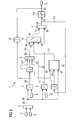
In Figur 1 ist ein Blockschaltbild eines Regel-Schaltkreises
dargestellt. In einem Subtrahier-Baustein 3 wird ein Wert für
eine Regelabweichung 25 aus einem Sollwert 2 und einem
Istwert 4 als Ausgangssignal 80 gebildet und zum weiteren
Baustein 5 geführt. Bei inversem Wirksinn des Reglers müssen
die Vorzeichen getauscht werden. Das Ausgangsignal 80 des
Subtrahier-Bausteins 3 wird an einen Eingang des weiteren
Bausteins 5 weitergeleitet. Der weitere Baustein 5 weist
einen weiteren Eingang auf, der mit einem Ausgang eines
Speicher-Bausteins 6 verbunden ist. Im Speicher-Baustein 6
ist ein Wert gespeichert, der als Ausgangsignal an den
weiteren Baustein 5 weitergeleitet wird. Der im Speicher-Baustein
6 gespeicherte Wert wird auch als Konstante KP
bezeichnet. Der weitere Baustein 5 ist derart ausgebildet,
dass der Wert der Regelabweichung 25 mit dem im Speicher-Baustein
6 gespeicherten Wert multipliziert wird und als
Ausgangsignal 59 an einen ersten Eingang 61 eines Umschalt-Additions-Bausteins
60 weitergeleitet wird.FIG. 1 shows a block diagram of a control circuit. In a
Das Ausgangssignal 80 wird auch an ein Integral-Inkrement-Baustein
9 weitergeleitet und dort mit einem Wert 10
multipliziert und als Ausgangsignal 71 zum Umschalt-Additions-Baustein
60 weitergeleitet. Der Wert 10 wird
gebildet aus dem Quotienten mit einer Zykluszeit ΔT und einer
Nachstellzeit TN eines Integrators.The
Der Umschalt-Additions-Baustein 60 weist vier Eingänge auf:
Den ersten Eingang 61 für das Ausgangssignal 59 des weiteren
Bausteins 5, einen zweiten Eingang 62 für ein Ausgangssignal
71 des Intergral-Inkrement-Bausteins 9, einen dritten Eingang
63 für ein Schaltsignal 21 aus einem Schalt-Baustein 12 und
einen vierten Eingang 64 für ein an einem Ausgang 82 eines
Minimum-Maximum-Begrenzers 14 anliegendem Stellgrößen-Signals
15. Der Schalt-Baustein 12 weist drei Eingänge 65, 66, 67
auf. An dem Eingang 67 liegt das Ausgangssignal 80 des
Subtrahier-Bausteins 3 an, am Eingang 65 liegt ein
Reglerausgangsignal 23 an und am Eingang 66 liegt das
Stellgrößensignal 15 an. Die Wirkungsweise des Schalt-Bausteins
12 ist in der Figur 4 beschrieben.The
Ein Ausgangssignal 68 des Umschalt-Additions-Bausteins 60
liegt an einem Eingang 81 des Minimum-Maximum-Begrenzers 14
an. Der Umschalt-Additions-Baustein 60 ist derart
ausgebildet, dass er zwischen einem ersten Zustand bei dem
das Ausgangssignal 59 des weiteren Bausteins 5 zur Berechnung
des Stellgrößensignals 15 addiert wird und einem zweiten
Zustand, bei dem Änderungen des Ausgangssignals 59 des
weiteren Bausteins 5 geblockt werden, umschaltbar ist.An
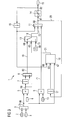
In der Figur 2 ist ein Blockschaltbild eines Regel-Schaltkreises
mit Darstellung eines Proportional- und
Integralanteils dargestellt. Der Umschalt-Additions-Baustein
60 umfasst in dieser Ausführungsform einen Umschalt-Baustein
13 und einen Additions-Baustein 11. Der Umschalt-Baustein 13
weist den dritten Eingang 63 und den vierten Eingang 64 auf.
Der Additions-Baustein 11 weist den zweiten Eingang 62 und
einen fünften Eingang 72 auf, der mit einem Ausgangssignal 18
des Umschalt-Bausteins 13 verbunden ist. Der erste Eingang 61
und der vierte Eingang 64 sind an einem Addier-Baustein 8
vorgesehen, der ein Ausgangsignal 83 liefert, das an einem
sechsten Eingang 69 des Umschalt-Bausteins 13 anliegt.FIG. 2 is a block diagram of a control circuit
with representation of a proportional and
Integral component shown. The
Im weiteren Baustein 5 wird das Ausgangssignal 59 gebildet,
das als weiterer Anteil bezeichnet wird, der zur Berechnung
des Stellgrößensignals 15 eingesetzt wird. Dieser weitere
Anteil ist in diesem Fall ein Proportionalanteil.In the
Das Stellgrößensignal 15 wird über einen ersten
Zwischenspeicher-Baustein 16 an den Addier-Baustein 8
weitergeleitet und wird auch als rückgemeldetes Signal YRück
bezeichnet.The manipulated
Das Reglerausgangssignal 23, das an dem Eingang 81 des
Minimum-Maximum-Begrenzer 14 anliegt wird über einen zweiten
Zwischenspeicher-Baustein 17 zum Schalt-Baustein 12
weitergeleitet.The
Es werden Veränderungen des weiteren Anteils aus dem weiteren
Baustein 5 gegenüber einem vorherigen Bearbeitungsschritt
weiterverarbeitet. Dazu gelangt das Ausgangssignal 59 aus dem
weiteren Baustein 5 zu einem dritten Zwischenspeicher-Baustein
7 und gelangt von dort zu dem Addier-Baustein 8. Der
dritte Zwischenspeicher-Baustein 7 kann als Halteglied 1.
Ordnung ausgebildet sein. Dies ist z.B. durch eine
entsprechende Abarbeitungsreihenfolge der Programmbausteine
darstellbar. Das Ausgangssignal 59 aus dem weiteren Baustein
5 wird ebenso direkt zum Addier-Baustein 8 geführt. Dies
verschafft die Möglichkeit, lediglich Änderungen des
Ausgangsignals 59 über eine Zykluszeit im Addier-Baustein 8
zu verarbeiten.There will be changes in the further share from the
Das Ausgangssignal 80 des Subtrahier-Bausteins 3 liegt an
dem Eingang 67 des Schalt-Bausteins 12 an. Der Schalt-Baustein
12 ist in Figur 4 näher beschrieben. Das
Ausgangsignal 18 liegt an dem fünften Eingang 72 des Addier-Bausteins
11 an und wird dort mit dem Ausgangsignal 71 des
Integral-Inkrement-Bausteins 9 multipliziert. An einem
Ausgang des Addier-Bausteins 11 liegt das
Reglerausgangssignal 23 an. Das Reglerausgangssignal 23 wird
mittels des Minimum-Maximum-Begrenzer 14 begrenzt und liegt
anschließend als Stellgrößensignal 15 vor.The
Ein Ausgang des Schalt-Bauteils 12 liegt am dritten Eingang
63 des Umschalt-Bausteins 13 an. Das aus dem ersten
Zwischenspeicher-Baustein 16 kommende Signal liegt am vierten
Eingang 64 des Umschalt-Bausteins 13 und am Eingang 66 des
Schalt-Bausteins 12 an. Die Funktion des Umschalt-Bausteins
13 hängt von dem Ausgang des Schalt-Bausteins 12 ab. In einem
unbegrenzten Betrieb hat der Umschalt-Baustein 13 die in der
Figur 2 beschriebene Stellung. Liefert der Schalt-Baustein 12
ein Schaltsignal 21 mit einem logischen Wert 1, ändert sich
die Funktion des Umschalt-Bausteins 13 wie folgt: das
Ausgangssignal 18 wird nicht mehr über eine Leitung 19 am
sechsten Eingang 69, sondern über eine Leitung 20 am vierten
Eingang 64 gebildet.An output of the
Zusätzlich wird das in einem vorherigen Zyklus berechnete und
anliegende Stellgrößensignal 15 nach dem ersten
Zwischenspeicher-Baustein 16 als Arbeitspunkt hinzuaddiert.
Mit den in Figur 2 dargestellten Zwischenspeicher-Bausteinen
7, 16 und 17 soll verdeutlicht werden, dass mit Rechenwerten
eines letzten Zyklusses gearbeitet wird.In addition, that calculated in a previous cycle and
adjacent manipulated
Liefert der Schalt-Baustein 12 ein Schaltsignal 21 mit einem
logischen Wert 1, so wird die Änderung des weiteren Anteils,
die als Ausgangssignal 59 am weiteren Baustein 5 anliegt,
vernachlässigt. Das neue Reglerausgangssignal 23 entsteht im
Addier-Baustein 11 durch die Addition des Ausgangssignals 71
des Integral-Inkrement-Bausteins 9 mit dem Signal YRück aus
dem ersten Zwischenspeicher-Baustein 16. Das
Reglerausgangssignal 23 wird durch ein Reglerunterprogramm
oder extern z. B. durch eine Minimum- oder Maximum-Auswahl
mit Ausgangssignalen anderer Regler begrenzt.If the
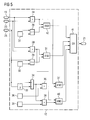
In der Figur 3 ist eine weitere Ausführungsform des Regel-Schaltkreises
dargestellt. Im Unterschied zur Figur 2 wird
hierbei ein Signal nach dem ersten Zwischenspeicher-Baustein
16 direkt an den Additions-Baustein 11 weitergeleitet. Im
Unterschied zur der in Figur 2 dargestellten Ausführungsform
weist der Additions-Baustein 11 nun einen weiteren Eingang
auf, der mit dem ersten Zwischenspeicher-Baustein 16
verbunden ist. Der in Figur 3 dargestellte Addier-Baustein 8
weist nun im Gegensatz zu der Ausführungsform des in Figur 2
dargestellten Addier-Bausteins 8 lediglich zwei Eingänge auf.
Dies führt zu dem Vorteil, dass das Stellgrößensignal 15
gemäß Figur 3 über dem ersten Zwischenspeicher-Baustein 16
direkt am Additions-Baustein 11 anliegt und das
Stellgrößensignal 15 unabhängig vom Umschalt-Baustein 13 am
Additions-Baustein 11 anliegt. Der Umschalt-Baustein 13 weist
einen siebten Eingang 73 auf, an dem ein Signal anliegt, das
dem Wert Null entspricht.
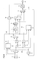
In der Figur 4 ist der Schalt-Baustein 12 näher dargestellt.
Kerngedanke ist hierbei, in Abhängigkeit von der
Regelabweichung 25 die Struktur des Reglers bei aktiver
Begrenzung umzuschalten. Das Schaltsignal 21 des Schalt-Bausteins
12 kann einen Wert annehmen, der einem logischen
Wert eins oder Null entspricht. Das Stellgrößensignal 15
wird mit dem Reglerausgangssignal 23 im Baustein 24
verglichen. Der Wert der Regelabweichung 25 wird im Baustein
26 mit einem vorgebbaren positiven Regelgrenzwert Xw,positiv 27
verglichen. Ist das Stellgrößensignal 15 kleiner als das
Reglerausgangssignal 23 und ist der Wert der Regelabweichung
25 größer oder gleich dem positiven Regelgrenzwert Xw,positiv
27, so entspricht das Schaltsignal 21 einem logischen Wert 1.
Das Stellgrößensignal 15 wird auch an den Baustein 28, in dem
eine negative Begrenzung berücksichtigt wird, weitergeleitet.
Ebenfalls zum Baustein 28 wird das Reglerausgangssignal 23
geleitet. Der Wert der Regelabweichung 25 wird im Baustein 29
mit einem vorgebbaren negativen Grenzwert Xw,negativ 30
verglichen. Ist das Stellgrößensignal 15 größer als das
Reglerausgangssignal 23 und ist der Wert der Regelabweichung
25 kleiner oder gleich dem negativen Regelgrenzwert Xw,negativ
30, so wird über einen Und-Baustein 31 und einem Oder-Baustein
32 ein Schaltsignal 21 gebildet, das einem logischen
Wert eins entspricht.FIG. 3 shows a further embodiment of the control circuit. In contrast to FIG. 2, in this case a signal is forwarded directly to the
In the figure 4, the switching
Treten diese Bedingungen nicht mehr auf, so liefert der Schalt-Baustein 12 einen Wert, der einem logischen Wert Null entspricht und der Regelalgorithmus wird umgeschaltet.If these conditions no longer occur, then the delivers Switching block 12 a value that is a logical value zero corresponds and the control algorithm is switched.
In einer alternativen Ausführungsform kann der RegelSchaltkreis
derart ausgebildet sein, dass ein inverser
Wirksinn möglich ist. Dabei fällt das Ausgangssignal bei
steigendem Sollwert. Dies wird erreicht durch Vertauschen der
Eingänge an dem Subtrahier-Baustein 3 und dem Addier-Baustein
46.In an alternative embodiment, the control circuit
be formed such that an inverse
Impact is possible. The output signal is included
increasing setpoint. This is achieved by swapping the
Inputs to the
In einer alternativen Ausführungsform wird der erste
Zwischenspeicher-Baustein 16 mit einem externen Signalgeber
verbunden. Über den externen Signalgeber werden über Minimumund
Maximum-Auswahlen noch andere Regler oder sonstige
Signale mit berücksichtigt. In an alternative embodiment, the
In der Figur 5 ist eine weitere Ausführungsform des Schalt-Bausteins
12 dargestellt. Im Vergleich zu der in Figur 4
dargestellten Ausführungsform des Schalt-Bausteins 12 sind in
der Figur 5 weitere Bausteine enthalten, die die Möglichkeit
schaffen, ein Rauschen der Regelabweichung 25 zu
berücksichtigen. Der Wert der Regelabweichung 25 liegt über
einen weiteren Zwischenspeicher-Baustein 33 und einem
Baustein 34 an einem Baustein 35 an. Im Baustein 35 wird eine
Änderung des Wertes der Regelabweichung 25 mit einem
vorgebbaren Grenzwert Δ Xw,positiv 36 verglichen. Tritt die
Bedingung ein, dass die Änderung des Wertes der
Regelabweichung 25 größer als der Grenzwert Δ Xw,positiv 36 ist,
wird ein logisches Signal an den Baustein 37 weitergeleitet.
Der Baustein 37 ist ein Und-Baustein. Ein zweites Signal, das
im Baustein 37 verarbeitet wird, kommt aus dem Baustein 24
und liefert ein Signal für eine obere Begrenzung. Die
Änderung des Wertes der Regelabweichung 25 wird ebenfalls an
den Baustein 38 weitergeleitet. Im Baustein 38 wird die
Änderung des Wertes der Regelabweichung 25 mit einem
vorgebbaren negativen Grenzwert Δ Xw,negativ 39 verglichen. Ist
die Änderung des Wertes der Regelabweichung 25 kleiner als
der Grenzwert Δ Xw,negativ 39, so wird ein Wert, der einem
logischen Wert 1 entspricht an den Baustein 40
weitergeleitet. Der Baustein 40 ist ein Und-Baustein. Zu
diesem Baustein 40 wird das Signal weitergeleitet, das aus
dem Baustein 28 kommt. Sind beide Signale mit einem Wert, der
einem logischen Wert 1 entspricht zum Baustein 40 angekommen,
so wird ein Wert, der einem logischen Wert 1 entspricht zum
Baustein 41 weitergeleitet. Der Baustein 41 ist ein Oder-Baustein,
der mit dem Baustein 32 aus der Figur 3
vergleichbar ist. Der Oder-Baustein 41 hat nun 4 Eingänge,
die von den Bausteinen 42, 31, 37 und 40 herrühren. Mit
anderen Worten wird hierbei in den Blöcken 33, 34 und 35
zusätzlich noch überwacht, ob sich der Wert der
Regelabweichung 25 im Betrieb an der Begrenzung nur minimal,
z. B. durch Signalrauschen von einem Regelzyklus zum nächsten
verändert hat. In einem solchen Fall wird ebenfalls eine
Änderung des weiteren Anteils vernachlässigt. Der
dargestellte Zwischenspeicher 33 kann auch ein Halteglied
höherer Ordnung oder ein beliebiger diskreter Filter, ein
Verzögerungselement oder ein Totzeitglied sein.FIG. 5 shows a further embodiment of the
In der in den Figuren 1, 2 und 3 dargestellten
Ausführungsformen des Regelschaltkreises weist der weitere
Anteil einen Proportional-Anteil auf. In der Figur 6 ist eine
weitere vorteilhafte Ausführungsform des Regel-Schaltkreises
dargestellt, wobei der weitere Anteil nun den
Proportionalanteil und einen Differentialanteil aufweist. In
einem Differenzialanteil-Baustein 42 wird ein Wert für den
Differenzialanteil aus dem Sollwert 2, dem Istwert 4, dem
Stellgrößensignal 15 und dem Reglerausgangssignal 23 gebildet
und an einen Addier-Baustein 43 als Ausgangssignal 19
weitergeleitet. Die Berechnung des Differenzialanteils
erfolgt nach den im Stand der Technik beschriebenen
Vorgehensweisen.In the illustrated in Figures 1, 2 and 3
Embodiments of the control circuit has the further
Share a proportional share. In the figure 6 is a
further advantageous embodiment of the control circuit
represented, with the remaining share now the
Proportional and a differential component has. In
a
In dem Addier-Baustein 43 wird das Ausgangssignal 19 des
Differentialanteil-Bausteins 42 und des weiteren Bausteins 5
zu einem Ausgangsignal 44 addiert und über den dritten
Zwischenspeicher-Baustein 7 an den Addier-Baustein 8
weitergeleitet und von dort über den Umschalt-Baustein 13 an
den Addier-Baustein 11 weitergeführt. Im Unterschied zu den
in den Figuren 1, 2 und 3 dargestellten Ausführungsformen
weist der weitere Anteil nun einen Differentialanteil und
einen Proportionalanteil auf.In the
Die Figur 7 zeigt eine Ausführungsform des
Differenzialanteil-Bausteins 42. Der Sollwert 2 und der
Istwert 4 werden zu einem Addier-Baustein 46 weitergeleitet.
Nach dem Addier-Baustein 46 gelangt ein Signal zu einem
Umschalt-Baustein 47. Der Istwert 4 wird ebenfalls direkt zum
Umschalt-Baustein 47 weitergeleitet. In einer alternativen
Ausführungsform kann der Istwert 4 mit einem Faktor -1
multipliziert, bevor das damit entstandene invertierte Signal
in den Umschalt-Baustein 47 gelangt. Über den Umschalt-Baustein
47 ist es möglich, Änderungen des Sollwertes 2 zur
Berechnung des Differential-Anteils zu berücksichtigen.FIG. 7 shows an embodiment of the
Mit dem Baustein 58 wird mit einem Ausgangssignal 74 des
Umschalt-Bausteins 47 ein Wert an einen Eingang 75 eines
Multiplikations-Bausteins 50 weitergeleitet. Der Baustein 58
ist kein Verzögerungsbaustein, sondern ein sogenanntes DT1-Element.
Es filtert und differenziert gewissermassen
gleichzeitig. Der Multiplikations-Baustein 50 weist einen
zweiten Eingang 76 auf.With the
Das Stellgrößensignal 15 und das Reglerausgangssignal 23 wird
im Vergleichs-Baustein 52 verglichen. Der Vergleichs-Baustein
52 liefert ein Ausgangssignal 77, das an einen Umschalt-Baustein
53 weitergeleitet wird. Wenn die Werte des
Reglerausgangssignal 23 und des Stellgrößensignals 15 gleich
sind, liefert der Vergleichs-Baustein 52 einen logischen Wert
1 als Ausgangssignal 77 und ansonsten einen logischen Wert
Null. Der Umschalt-Baustein 53 weist einen mit einem dem Wert
Null enthaltenen Speicher-Baustein 57 verbundenen ersten
Eingang 78 und einen mit einem Wert für eine Vorhaltezeit 84
enthaltenen zweiten Speicher-Baustein 56 verbundenen zweiten
Eingang 79 auf. Ein Ausgangssignal 54 liegt an einem Eingang
85 eines Steigungsbegrenzungs-Baustein 55 an.The manipulated
Liegt an dem Umschalt-Baustein 53 das Ausgangssignal 77 mit
einem logischen Wert eins an, dann wird der Wert des
Speicher-Bausteins 56 an den Steigungsbegrenzungs-Baustein 55
weitergeleitet. Ansonsten wird der Wert Null des Speicher-Bausteins
57 an den Steigungsbegrenzungs-Baustein 55
weitergeleitet. Ein Ausgangssignal 51 des
Steigungsbegrenzungs-Bausteins 55 liegt an dem zweiten
Eingang 76 des Multiplikations-Bausteins 50 an. If the
Im Multiplikations-Baustein 50 werden die an den Eingängen 75
und 76 anliegenden Signale zu dem Ausgangssignal 19
multipliziert. Auf diese Weise wird der differenzierende
Anteil an den Stellbereichsgrenzen herausgenommen.
Signalrauschen führt nicht mehr zum verlassen der Begrenzung.
Ein stoßfreies Wiedereinsetzen des differenzierenden Anteils
ist dadurch gewährleistet.In the
Claims (25)
dadurch gekennzeichnet,dass der Wert des Stellgrößensignals (15) zuerst mit dem Regelalgorithmus berechnet wird und nach einem Minimum-Maximum-Begrenzer (14) begrenzt und an den Regelalgorithmus zurückgemeldet wird,
wobei eine Änderung des weiteren Anteils vernachlässigt wird, wenn folgende Bedingungen eintreten:
oder
characterized in that the value of the manipulated variable signal (15) is first calculated with the control algorithm and limited to a minimum-maximum limiter (14) and fed back to the control algorithm,
a change of the remaining share is neglected if the following conditions occur:
or
dadurch gekennzeichnet,dass
der weitere Anteil ein Proportionalanteil ist.Method according to claim 1,
characterized in that
the further part is a proportional part.
dadurch gekennzeichnet, dass
der Regelalgorithmus einen Differenzialanteil aufweist.Method according to claim 1 or 2,
characterized in that
the control algorithm has a derivative component.
dadurch gekennzeichnet, dass
der Differenzialanteil zum weiteren Anteil addiert wird.Method according to one of claims 1 to 3,
characterized in that
the differential share is added to the further share.
dadurch gekennzeichnet, dass
der weitere Anteil vernachlässigt wird, wenn folgende Bedingung zusätzlich eintritt:
oder
characterized in that
the additional share is neglected if the following additional condition occurs:
or
dadurch gekennzeichnet, dass
Änderungen des Sollwertes (2) zur Berechnung des Differentialanteils berücksichtigt werden können. Method according to one of claims 3 to 5,
characterized in that
Changes in the setpoint (2) for calculating the differential component can be taken into account.
dadurch gekennzeichnet, dass
der Differentialanteil mit einer einstellbaren Zeitkonstanten gefiltert wird.Method according to one of claims 3 to 6,
characterized in that
the differential component is filtered with an adjustable time constant.
einem Integral-Inkrement-Baustein (9) zum Berechnen eines Integral-Inkrement-Anteils für das Stellgrößensignal (15) als Ausgangssignal aufgrund der Regelabweichung (25),
einem weiteren Baustein (5) zum Berechnen eines weiteren Anteils für das Stellgrößensignal (15) als Ausgangssignal aufgrund der Regelabweichung (25),
gekennzeichnet durch
einen Umschalt-Additions-Baustein (60),
der einen ersten Eingang (61) für das Ausgangssignal (70) des weiteren Bausteins (5),
einen zweiten Eingang (62) für das Ausgangssignal (71) des Integral-Inkrement-Bausteins (9),
einen dritten Eingang (63) für ein Schaltsignal (21) und einen vierten Eingang (64) für ein Signal aus einem Minimum-Maximum-Begrenzer (14), der zur Begrenzung des Wertes für das Stellgrößensignal (15) auf einen voreingestellten Wert ausgebildet ist, aufweist und
zum Berechnen eines Wertes für die Stellgröße (15) als Ausgangssignal aufgrund des weiteren Bausteins (5), dem Ausgangssignal des Integral-Inkrement-Baustein (9) und des Signals (22) aus dem Minimum-Maximum-Begrenzers (14) ausgebildet ist,
wobei der Umschalt-Additions-Baustein (60) zwischen einem ersten Zustand, bei dem das Ausgangssignal (70) des weiteren Bausteins (5) zur Berechnung des Stellgrößensignals (15) addiert wird und einem zweiten Zustand, bei dem das Ausgangssignal (70) des weiteren Bausteins (5) geblockt wird, umschaltbar ist,
und
einen Schalt-Baustein (12) zum Erzeugen des Schaltsignals (21) für den Umschalt-Additions-Baustein (60), wobei der Schalt-Baustein (12) derart ausgebildet ist,
dass ein Schaltsignal (21) zum Umschalten in den zweiten Zustand an den Umschalt-Additions-Baustein (60) gesendet wird, wenn der Wert des Stellgrößensignals (15) größer als der nach dem Minimum-Maximum-Begrenzer (14) voreingestellte Wert ist und die Regelabweichung (25) größer oder gleich einem vorgebbaren Grenzwert Xw,positiv ist
oder
wenn der Wert des Stellgrößensignals (15) kleiner als der nach dem Minimum-Maximum-Begrenzer (14) voreingestellte Wert ist und die Regelabweichung (25) kleiner oder gleich einem vorgebbaren Grenzwert Xw,negativ ist. Device for controlling a controlled variable, which can be changed via an actuating variable signal (15), with a subtracting module (3) for calculating a control deviation (25) by subtracting a nominal value (2) of the controlled variable from an actual value (4) of the controlled variable,
an integral increment module (9) for calculating an integral increment component for the manipulated variable signal (15) as an output signal due to the control deviation (25),
a further component (5) for calculating a further component for the manipulated variable signal (15) as output signal on the basis of the control deviation (25),
marked by
a shift addition module (60),
a first input (61) for the output signal (70) of the further module (5),
a second input (62) for the output signal (71) of the integral increment module (9),
a third input (63) for a switching signal (21) and a fourth input (64) for a signal from a minimum-maximum limiter (14), which is designed to limit the value for the manipulated variable signal (15) to a preset value , and
for calculating a value for the manipulated variable (15) as an output signal on the basis of the further block (5), the output signal of the integral increment block (9) and the signal (22) from the minimum-maximum limiter (14),
wherein the switching-addition-block (60) between a first state in which the output signal (70) of the further block (5) for calculating the manipulated variable signal (15) is added and a second state in which the output signal (70) of the further block (5) is blocked, is switchable,
and
a switching component (12) for generating the switching signal (21) for the switching-addition component (60), wherein the switching component (12) is designed in such a way that
that a switching signal (21) for switching to the second state is sent to the switching-addition block (60) if the value of the manipulated variable signal (15) is greater than the value preset after the minimum-maximum limiter (14), and the control deviation (25) is greater than or equal to a predefinable limit value X w, positive
or
if the value of the manipulated variable signal (15) is smaller than the value preset after the minimum-maximum limiter (14) and the control deviation (25) is less than or equal to a predefinable limit value X w, is negative .
dadurch gekennzeichnet, dass
der Schall-Baustein (12) derart ausgebildet ist, dass ein Schaltsignal (21) vom Schall-Baustein (12) an den Umschalt-Additions-Baustein (60) gesendet wird, wenn der Wert des Stellgrößensignals (15) größer als der nach dem Minimum-Maximum-Begrenzer (14) eingestellte Wert ist
und
eine Änderung der Regelabweichung (25) größer einem vorgebbaren Grenzwert Δ Xw,positiv ist
oder
der Wert des Stellgrößensignals (15) kleiner als der nach dem Minimum-Maximum-Begrenzer (14) eingestellte Wert ist
und
eine Änderung der Regelabweichung (25) kleiner einem vorgebbaren Grenzwert Δ Xw,negativ ist.Device according to claim 9,
characterized in that
the sound module (12) is designed such that a switching signal (21) from the sound module (12) to the switching-addition module (60) is sent when the value of the manipulated variable signal (15) greater than that after the Minimum-maximum limiter (14) is set value
and
a change in the control deviation (25) greater than a predefinable limit value ΔX w, is positive
or
the value of the manipulated variable signal (15) is smaller than the value set after the minimum-maximum limiter (14)
and
a change in the control deviation (25) smaller than a predefinable limit value ΔX w, is negative .
dadurch gekennzeichnet, dass
der Umschalt-Additions-Baustein (60) einen Umschalt-Baustein (13) mit dem ersten (61), dritten (63) und vierten (64) Eingang und einen Additions-Baustein (11) mit dem zweiten Eingang (62) und einen fünften Eingang (72) für ein Ausgangssignal (18) des Umschalt-Bausteins (13) umfasst.Device according to claim 9 or 10,
characterized in that
the toggle addition device (60) comprises a switching device (13) having the first (61), third (63) and fourth (64) inputs and an addition device (11) having the second input (62) and a fifth input (72) for an output signal (18) of the switching block (13).
dadurch gekennzeichnet, dass
der Umschalt-Baustein (13),
der erste (61) und vierte Eingang (64) zu einem sechsten Eingang (69) für ein Signal zusammengefasst ist, das aus der Summe des Ausgangssignals des weiteren Bausteins (5) und des Signals aus dem Minimum-Maximum-Begrenzer (14) gebildet ist,
den für den vierten Eingang (64) für das Signal aus dem Minimum-Maximum-Begrenzer (14) und den dritten Eingang (63) für das Schaltsignal (21) aufweist,
sowie
zwischen einem ersten Zustand, bei dem nur das Signal am sechsten Eingang (69) als Ausgangssignal (18) durchgeleitet wird und einem zweiten Zustand, bei dem nur das Signal am vierten Eingang (64) als Ausgangssignal (18) durchgeleitet wird, umschaltbar ist.Device according to claim 11,
characterized in that
the switching module (13),
the first (61) and fourth input (64) are combined to form a sixth input (69) for a signal which is formed from the sum of the output signal of the further module (5) and the signal from the minimum-maximum limiter (14) is
for the fourth input (64) for the signal from the minimum-maximum limiter (14) and the third input (63) for the switching signal (21),
such as
between a first state in which only the signal at the sixth input (69) as an output signal (18) is passed through and a second state in which only the signal at the fourth input (64) as an output signal (18) is passed, switchable.
dadurch gekennzeichnet, dass
der Additions-Baustein (11) ausgebildet ist zum Addieren des Ausgangssignals (18) des Umschalt-Bausteins (13) und des Ausgangssignals (71) des Integral-Inkrement-Bausteins (9) zu einem Ausgangssignal.Device according to claim 12,
characterized in that
the addition component (11) is designed to add the output signal (18) of the switching component (13) and the output signal (71) of the integral increment component (9) to an output signal.
dadurch gekennzeichnet, dass
der Umschalt-Additions-Baustein (60) einen Umschalt-Baustein (13) mit dem ersten (61) und dritten (63) Eingang und einen Additions-Baustein (11) mit dem zweiten (62), vierten (64) Eingang und den fünften Eingang (72) für das Ausgangssignal (18) des Umschalt-Bausteins (13) umfasst. Device according to claim 9 or 10,
characterized in that
the toggle addition device (60) comprises a switching device (13) having the first (61) and third (63) inputs and an addition device (11) having the second (62), fourth (64) inputs and the fifth input (72) for the output signal (18) of the switching module (13).
dadurch gekennzeichnet, dass
der Umschalt-Baustein (13)
einen siebten Eingang (73) für ein den Wert 0 aufweisendes Signal aufweist
sowie
zwischen einem ersten Zustand, bei dem das Ausgangssignal (59) des weiteren Bausteins als Ausgangssignal (18) durchgeleitet wird und
einem zweiten Zustand, bei dem das den Wert 0 aufweisende Signal durchgeleitet wird, umschaltbar ist.Device according to claim 14,
characterized in that
the switching module (13)
a seventh input (73) for a signal having the value 0 has
such as
between a first state, in which the output signal (59) of the further block as an output signal (18) is passed through and
a second state in which the signal having the value 0 is passed, can be switched.
dadurch gekennzeichnet, dass
der Additions-Baustein (11) ausgebildet ist zum Addieren des Ausgangssignals (18) des Umschalt-Bausteins (13), des Ausgangssignals (71) des Integral-Inkrement-Bausteins (9) und des Signals aus dem Minimum-Maximum-Begrenzers (14) zu einem Ausgangssignal (68).Device according to claim 15,
characterized in that
the addition component (11) is designed to add the output signal (18) of the switching component (13), the output signal (71) of the integral increment component (9) and the signal from the minimum-maximum limiter (14 ) to an output signal (68).
dadurch gekennzeichnet, dass
der weitere Baustein (5) einen Proportional-Anteil-Baustein und einen Differentialanteil-Baustein (42) umfasst.Device according to one of claims 9 to 16,
characterized in that
the further component (5) comprises a proportional component component and a differential component component (42).
dadurch gekennzeichnet, dass
der Differenzialanteil-Baustein (42) zum Berechnen eines Differenzialanteils für das Stellgrößensignal (15) als Ausgangssignal aufgrund
der Regelabweichung (25),
des Signals (22) aus dem Minimum-Maximum-Begrenzer (14) und
eines Ausgangsignals (23) des Additions-Bausteines (11) vorgesehen ist.Device according to claim 17,
characterized in that
the differential component (42) for calculating a differential component for the manipulated variable signal (15) as an output signal
the control deviation (25),
the signal (22) from the minimum-maximum limiter (14) and
an output signal (23) of the addition module (11) is provided.
dadurch gekennzeichnet, dass
der Proportionalanteil-Baustein (5) zum Berechnen eines Proportionalanteils für das Stellgrößensignal (15) als Ausgangssignal aufgrund der Regelabweichung (25) vorgesehen ist.Device according to claim 17 or 18,
characterized in that
the proportional component (5) is provided for calculating a proportional component for the manipulated variable signal (15) as an output signal due to the control deviation (25).
dadurch gekennzeichnet, dass
ein Additionsbaustein (11) zum Addieren des Ausgangssignals des Differentialanteil-Bausteins (42) und des Ausgangssignals des Proportionalanteil-Bausteins (5) als Ausgangssignal für den weiteren Anteil vorgesehen ist.Device according to one of claims 16 to 19,
characterized in that
an addition block (11) is provided for adding the output signal of the differential component block (42) and the output signal of the proportional component block (5) as an output signal for the further portion.
dadurch gekennzeichnet, dass
der Differenzialanteil-Baustein (42) einen Umschalt-Baustein (13) aufweist, der
einen ersten Eingang für den Wert der Regelgröße und
einen zweiten Eingang für den Wert der Regelabweichung (25) aufweist
sowie
zwischen einem ersten Zustand, bei dem die Änderung des Sollwertes (2) durchgeleitet wird und einem zweiten Zustand, bei dem nur die Regelabweichung (25) weitergeleitet wird, umschaltbar ist.Device according to one of claims 16 or 20,
characterized in that
the differential component component (42) has a switching component (13) which
a first input for the value of the controlled variable and
has a second input for the value of the control deviation (25)
such as
between a first state, in which the change of the setpoint value (2) is passed through and a second state, in which only the control deviation (25) is forwarded, can be switched over.
dadurch gekennzeichnet, dass
der Differenzialanteil-Baustein (42) einen Verzögerungs-Baustein (48) zum Berechnen des Differentialanteils aufweist.Device according to one of claims 9 to 21,
characterized in that
the differential component component (42) has a delay component (48) for calculating the differential component.
dadurch gekennzeichnet, dass
ein erster Zwischenspeicher-Baustein (16) zum Zwischenspeichern eines Signals als Ausgangssignal vorgesehen ist,
der mit dem nach dem Minimum-Maximum-Begrenzer (14) vorhandenen Signal verbunden ist und
das Ausgangssignal des ersten Zwischenspeicher-Bausteins (16) mit dem Umschalt-Addier-Baustein (60) oder mit dem Addier-Baustein (11) verbunden ist.Device according to one of claims 9 to 22,
characterized in that
a first buffer block (16) is provided for buffering a signal as an output signal,
which is connected to the signal present after the minimum-maximum limiter (14) and
the output signal of the first buffer memory block (16) is connected to the switchover adder block (60) or to the adder block (11).
dadurch gekennzeichnet, dass
ein zweiter Zwischenspeicher-Baustein (17) zum Zwischenspeichern eines Signals als Ausgangssignal vorgesehen ist,
der mit dem Ausgangsignals des Additions-Bausteins (11) verbunden ist und
das Ausgangssignal des Zwischenspeicher-Bausteins (17) mit dem Schalt-Baustein (12) verbunden ist. Device according to one of claims 9 to 23
characterized in that
a second buffer memory unit (17) is provided for latching a signal as an output signal,
which is connected to the output signal of the addition module (11) and
the output signal of the intermediate memory module (17) is connected to the switching component (12).
dadurch gekennzeichnet, dass
ein dritter Zwischenspeicher-Baustein (7) zum Zwischenspeichern eines Signals als Ausgangssignal vorgesehen ist,
der mit dem Ausgangssignal des weiteren Bausteins (5) verbunden ist und
das Ausgangssignal des weiteren Zwischenspeicher-Bausteins mit dem ersten Eingang (61) des Umschalt-Additions-Bausteins (60) verbunden ist.Device according to one of claims 9 to 24,
characterized in that
a third buffer memory device (7) is provided for latching a signal as an output signal,
which is connected to the output signal of the further module (5) and
the output signal of the further buffer block is connected to the first input (61) of the switching-addition module (60).
Priority Applications (1)
| Application Number | Priority Date | Filing Date | Title |
|---|---|---|---|
| EP03020210.5A EP1513033B1 (en) | 2003-09-05 | 2003-09-05 | Method and device for controlling a controlled variable |
Applications Claiming Priority (1)
| Application Number | Priority Date | Filing Date | Title |
|---|---|---|---|
| EP03020210.5A EP1513033B1 (en) | 2003-09-05 | 2003-09-05 | Method and device for controlling a controlled variable |
Publications (2)
| Publication Number | Publication Date |
|---|---|
| EP1513033A1 true EP1513033A1 (en) | 2005-03-09 |
| EP1513033B1 EP1513033B1 (en) | 2016-08-31 |
Family
ID=34130156
Family Applications (1)
| Application Number | Title | Priority Date | Filing Date |
|---|---|---|---|
| EP03020210.5A Expired - Lifetime EP1513033B1 (en) | 2003-09-05 | 2003-09-05 | Method and device for controlling a controlled variable |
Country Status (1)
| Country | Link |
|---|---|
| EP (1) | EP1513033B1 (en) |
Citations (4)
| Publication number | Priority date | Publication date | Assignee | Title |
|---|---|---|---|---|
| EP0533148A1 (en) * | 1991-09-18 | 1993-03-24 | Samsung Electronics Co., Ltd. | Limiter circuit of servo motor control apparatus |
| US5270916A (en) * | 1990-02-27 | 1993-12-14 | Ge Fanuc Automation North America, Inc. | Apparatus and method for preventing runaway of the integral term of a proportional plus integral controller |
| US5298845A (en) * | 1991-10-31 | 1994-03-29 | Johnson Service Company | Anti-windup proportional plus integral controller |
| US5303142A (en) * | 1989-10-06 | 1994-04-12 | United Technologies Corporation | Control system for gas turbine helicopter engines and the like |
-
2003
- 2003-09-05 EP EP03020210.5A patent/EP1513033B1/en not_active Expired - Lifetime
Patent Citations (4)
| Publication number | Priority date | Publication date | Assignee | Title |
|---|---|---|---|---|
| US5303142A (en) * | 1989-10-06 | 1994-04-12 | United Technologies Corporation | Control system for gas turbine helicopter engines and the like |
| US5270916A (en) * | 1990-02-27 | 1993-12-14 | Ge Fanuc Automation North America, Inc. | Apparatus and method for preventing runaway of the integral term of a proportional plus integral controller |
| EP0533148A1 (en) * | 1991-09-18 | 1993-03-24 | Samsung Electronics Co., Ltd. | Limiter circuit of servo motor control apparatus |
| US5298845A (en) * | 1991-10-31 | 1994-03-29 | Johnson Service Company | Anti-windup proportional plus integral controller |
Non-Patent Citations (1)
| Title |
|---|
| LEHRBUCH: "Regelungstechnik-ein praxisorientiertes Lehrbuch", VERLAG HARRI DEUTSCH |
Also Published As
| Publication number | Publication date |
|---|---|
| EP1513033B1 (en) | 2016-08-31 |
Similar Documents
| Publication | Publication Date | Title |
|---|---|---|
| EP0132487B1 (en) | Process for controlling at least two turbo compressors mounted in parallel | |
| DE4104642C2 (en) | PID or PI controller | |
| DE2347741A1 (en) | PROCESS REGULATION ORGANIZATION WITH AUTOMATIC ADAPTATION TO UNKNOWN OR CHANGEABLE PARAMETERS | |
| WO2000022487A1 (en) | Controlling system for regulating a system with several coupled controlled variables | |
| DE102018206114A1 (en) | Method for driving a valve and corresponding device | |
| EP0752630B1 (en) | Controlling device and method for the self-adjustment of this device | |
| EP3507656B1 (en) | Control device with adjustable control behavior | |
| EP1490735B1 (en) | Method and controller for the adaptive control of at least one component of a technical plant | |
| DE4418997C2 (en) | Field-oriented control for a three-phase motor fed via a voltage pulse inverter | |
| EP3438773A1 (en) | Processing of workpieces with model-supported error compensation | |
| EP3652597B1 (en) | Automated assessment of machine behaviour | |
| EP1513033B1 (en) | Method and device for controlling a controlled variable | |
| EP0473914A2 (en) | Control system for an actuator in an internal combustion engine | |
| EP1229411B1 (en) | Control process and structure of regulation for the motion control, feed forward and fine interpolation of objects in a rotation speed regulator cycle which is faster than the position regulator cycle | |
| DE2343511C2 (en) | Control device with automatic adaptation of the control parameters | |
| DE4120000A1 (en) | Limiting control action particularly for vehicle engine speed - having error signal integrated to generate signal that limits output if signal exceeds current error signal level | |
| EP2482147B1 (en) | Method for adjusting the clock frequency of a microprocessor of an industrial automation component and automation component with a microprocessor with adjustable clock frequency | |
| DE2638456C3 (en) | Procedure for starting control loops | |
| EP0700536B1 (en) | Regulating device | |
| DE10055166C5 (en) | Method for controlling the power and speed of a turbine | |
| EP0724748B1 (en) | Control device | |
| DE19635981C2 (en) | Process for direct control of the speed of an electric drive | |
| DE102007062173A1 (en) | Internal-combustion engine operating method for motor vehicle, involves determining maximum and momentary moments and pre-determining reference values of idle speed in dependent of maximum and momentary moments of engine | |
| DE4333804C2 (en) | Control device | |
| DE2943354A1 (en) | Start=up control for process regulator - has facility for correction of command if preset limits are exceeded |
Legal Events
| Date | Code | Title | Description |
|---|---|---|---|
| PUAI | Public reference made under article 153(3) epc to a published international application that has entered the european phase |
Free format text: ORIGINAL CODE: 0009012 |
|
| AK | Designated contracting states |
Kind code of ref document: A1 Designated state(s): AT BE BG CH CY CZ DE DK EE ES FI FR GB GR HU IE IT LI LU MC NL PT RO SE SI SK TR |
|
| AX | Request for extension of the european patent |
Extension state: AL LT LV MK |
|
| 17P | Request for examination filed |
Effective date: 20050404 |
|
| AKX | Designation fees paid |
Designated state(s): AT BE BG CH CY CZ DE DK EE ES FI FR GB GR HU IE IT LI LU MC NL PT RO SE SI SK TR |
|
| 17Q | First examination report despatched |
Effective date: 20110131 |
|
| RAP1 | Party data changed (applicant data changed or rights of an application transferred) |
Owner name: SIEMENS AKTIENGESELLSCHAFT |
|
| RAP1 | Party data changed (applicant data changed or rights of an application transferred) |
Owner name: SIEMENS AKTIENGESELLSCHAFT |
|
| GRAP | Despatch of communication of intention to grant a patent |
Free format text: ORIGINAL CODE: EPIDOSNIGR1 |
|
| INTG | Intention to grant announced |
Effective date: 20160323 |
|
| GRAS | Grant fee paid |
Free format text: ORIGINAL CODE: EPIDOSNIGR3 |
|
| GRAA | (expected) grant |
Free format text: ORIGINAL CODE: 0009210 |
|
| AK | Designated contracting states |
Kind code of ref document: B1 Designated state(s): AT BE BG CH CY CZ DE DK EE ES FI FR GB GR HU IE IT LI LU MC NL PT RO SE SI SK TR |
|
| REG | Reference to a national code |
Ref country code: CH Ref legal event code: EP Ref country code: CH Ref legal event code: NV Representative=s name: SIEMENS SCHWEIZ AG, CH Ref country code: GB Ref legal event code: FG4D Free format text: NOT ENGLISH |
|
| REG | Reference to a national code |
Ref country code: IE Ref legal event code: FG4D Free format text: LANGUAGE OF EP DOCUMENT: GERMAN |
|
| REG | Reference to a national code |
Ref country code: DE Ref legal event code: R096 Ref document number: 50315530 Country of ref document: DE |
|
| REG | Reference to a national code |
Ref country code: AT Ref legal event code: REF Ref document number: 825493 Country of ref document: AT Kind code of ref document: T Effective date: 20161015 |
|
| REG | Reference to a national code |
Ref country code: NL Ref legal event code: FP |
|
| PG25 | Lapsed in a contracting state [announced via postgrant information from national office to epo] |
Ref country code: FI Free format text: LAPSE BECAUSE OF FAILURE TO SUBMIT A TRANSLATION OF THE DESCRIPTION OR TO PAY THE FEE WITHIN THE PRESCRIBED TIME-LIMIT Effective date: 20160831 |
|
| PG25 | Lapsed in a contracting state [announced via postgrant information from national office to epo] |
Ref country code: GR Free format text: LAPSE BECAUSE OF FAILURE TO SUBMIT A TRANSLATION OF THE DESCRIPTION OR TO PAY THE FEE WITHIN THE PRESCRIBED TIME-LIMIT Effective date: 20161201 Ref country code: BE Free format text: LAPSE BECAUSE OF NON-PAYMENT OF DUE FEES Effective date: 20160930 Ref country code: ES Free format text: LAPSE BECAUSE OF FAILURE TO SUBMIT A TRANSLATION OF THE DESCRIPTION OR TO PAY THE FEE WITHIN THE PRESCRIBED TIME-LIMIT Effective date: 20160831 Ref country code: SE Free format text: LAPSE BECAUSE OF FAILURE TO SUBMIT A TRANSLATION OF THE DESCRIPTION OR TO PAY THE FEE WITHIN THE PRESCRIBED TIME-LIMIT Effective date: 20160831 |
|
| PG25 | Lapsed in a contracting state [announced via postgrant information from national office to epo] |
Ref country code: EE Free format text: LAPSE BECAUSE OF FAILURE TO SUBMIT A TRANSLATION OF THE DESCRIPTION OR TO PAY THE FEE WITHIN THE PRESCRIBED TIME-LIMIT Effective date: 20160831 Ref country code: RO Free format text: LAPSE BECAUSE OF FAILURE TO SUBMIT A TRANSLATION OF THE DESCRIPTION OR TO PAY THE FEE WITHIN THE PRESCRIBED TIME-LIMIT Effective date: 20160831 |
|
| PG25 | Lapsed in a contracting state [announced via postgrant information from national office to epo] |
Ref country code: DK Free format text: LAPSE BECAUSE OF FAILURE TO SUBMIT A TRANSLATION OF THE DESCRIPTION OR TO PAY THE FEE WITHIN THE PRESCRIBED TIME-LIMIT Effective date: 20160831 Ref country code: CZ Free format text: LAPSE BECAUSE OF FAILURE TO SUBMIT A TRANSLATION OF THE DESCRIPTION OR TO PAY THE FEE WITHIN THE PRESCRIBED TIME-LIMIT Effective date: 20160831 Ref country code: SK Free format text: LAPSE BECAUSE OF FAILURE TO SUBMIT A TRANSLATION OF THE DESCRIPTION OR TO PAY THE FEE WITHIN THE PRESCRIBED TIME-LIMIT Effective date: 20160831 Ref country code: PT Free format text: LAPSE BECAUSE OF FAILURE TO SUBMIT A TRANSLATION OF THE DESCRIPTION OR TO PAY THE FEE WITHIN THE PRESCRIBED TIME-LIMIT Effective date: 20170102 Ref country code: BG Free format text: LAPSE BECAUSE OF FAILURE TO SUBMIT A TRANSLATION OF THE DESCRIPTION OR TO PAY THE FEE WITHIN THE PRESCRIBED TIME-LIMIT Effective date: 20161130 |
|
| REG | Reference to a national code |
Ref country code: DE Ref legal event code: R097 Ref document number: 50315530 Country of ref document: DE |
|
| REG | Reference to a national code |
Ref country code: IE Ref legal event code: MM4A |
|
| PLBE | No opposition filed within time limit |
Free format text: ORIGINAL CODE: 0009261 |
|
| STAA | Information on the status of an ep patent application or granted ep patent |
Free format text: STATUS: NO OPPOSITION FILED WITHIN TIME LIMIT |
|
| GBPC | Gb: european patent ceased through non-payment of renewal fee |
Effective date: 20161130 |
|
| PG25 | Lapsed in a contracting state [announced via postgrant information from national office to epo] |
Ref country code: IE Free format text: LAPSE BECAUSE OF NON-PAYMENT OF DUE FEES Effective date: 20160905 |
|
| 26N | No opposition filed |
Effective date: 20170601 |
|
| REG | Reference to a national code |
Ref country code: FR Ref legal event code: ST Effective date: 20170713 |
|
| PG25 | Lapsed in a contracting state [announced via postgrant information from national office to epo] |
Ref country code: LU Free format text: LAPSE BECAUSE OF NON-PAYMENT OF DUE FEES Effective date: 20160905 Ref country code: SI Free format text: LAPSE BECAUSE OF FAILURE TO SUBMIT A TRANSLATION OF THE DESCRIPTION OR TO PAY THE FEE WITHIN THE PRESCRIBED TIME-LIMIT Effective date: 20160831 |
|
| REG | Reference to a national code |
Ref country code: CH Ref legal event code: PCOW Free format text: NEW ADDRESS: WERNER-VON-SIEMENS-STRASSE 1, 80333 MUENCHEN (DE) |
|
| PG25 | Lapsed in a contracting state [announced via postgrant information from national office to epo] |
Ref country code: FR Free format text: LAPSE BECAUSE OF NON-PAYMENT OF DUE FEES Effective date: 20161102 |
|
| REG | Reference to a national code |
Ref country code: AT Ref legal event code: MM01 Ref document number: 825493 Country of ref document: AT Kind code of ref document: T Effective date: 20160905 |
|
| REG | Reference to a national code |
Ref country code: BE Ref legal event code: MM Effective date: 20160930 |
|
| PG25 | Lapsed in a contracting state [announced via postgrant information from national office to epo] |
Ref country code: GB Free format text: LAPSE BECAUSE OF NON-PAYMENT OF DUE FEES Effective date: 20161130 |
|
| PG25 | Lapsed in a contracting state [announced via postgrant information from national office to epo] |
Ref country code: AT Free format text: LAPSE BECAUSE OF NON-PAYMENT OF DUE FEES Effective date: 20160905 |
|
| PG25 | Lapsed in a contracting state [announced via postgrant information from national office to epo] |
Ref country code: CY Free format text: LAPSE BECAUSE OF FAILURE TO SUBMIT A TRANSLATION OF THE DESCRIPTION OR TO PAY THE FEE WITHIN THE PRESCRIBED TIME-LIMIT Effective date: 20160831 Ref country code: HU Free format text: LAPSE BECAUSE OF FAILURE TO SUBMIT A TRANSLATION OF THE DESCRIPTION OR TO PAY THE FEE WITHIN THE PRESCRIBED TIME-LIMIT; INVALID AB INITIO Effective date: 20030905 |
|
| PG25 | Lapsed in a contracting state [announced via postgrant information from national office to epo] |
Ref country code: MC Free format text: LAPSE BECAUSE OF FAILURE TO SUBMIT A TRANSLATION OF THE DESCRIPTION OR TO PAY THE FEE WITHIN THE PRESCRIBED TIME-LIMIT Effective date: 20160831 Ref country code: TR Free format text: LAPSE BECAUSE OF FAILURE TO SUBMIT A TRANSLATION OF THE DESCRIPTION OR TO PAY THE FEE WITHIN THE PRESCRIBED TIME-LIMIT Effective date: 20160831 |
|
| REG | Reference to a national code |
Ref country code: DE Ref legal event code: R081 Ref document number: 50315530 Country of ref document: DE Owner name: SIEMENS ENERGY GLOBAL GMBH & CO. KG, DE Free format text: FORMER OWNER: SIEMENS AKTIENGESELLSCHAFT, 80333 MUENCHEN, DE |
|
| PGFP | Annual fee paid to national office [announced via postgrant information from national office to epo] |
Ref country code: NL Payment date: 20220908 Year of fee payment: 20 Ref country code: DE Payment date: 20220617 Year of fee payment: 20 |
|
| REG | Reference to a national code |
Ref country code: NL Ref legal event code: PD Owner name: SIEMENS ENERGY GLOBAL GMBH & CO. KG; DE Free format text: DETAILS ASSIGNMENT: CHANGE OF OWNER(S), ASSIGNMENT; FORMER OWNER NAME: SIEMENS AKTIENGESELLSCHAFT Effective date: 20221220 |
|
| PGFP | Annual fee paid to national office [announced via postgrant information from national office to epo] |
Ref country code: IT Payment date: 20220926 Year of fee payment: 20 |
|
| PGFP | Annual fee paid to national office [announced via postgrant information from national office to epo] |
Ref country code: CH Payment date: 20221207 Year of fee payment: 20 |
|
| REG | Reference to a national code |
Ref country code: DE Ref legal event code: R071 Ref document number: 50315530 Country of ref document: DE |
|
| REG | Reference to a national code |
Ref country code: NL Ref legal event code: MK Effective date: 20230904 |
|
| REG | Reference to a national code |
Ref country code: CH Ref legal event code: PL |