EP1463178A2 - Power generating device - Google Patents
Power generating device Download PDFInfo
- Publication number
- EP1463178A2 EP1463178A2 EP04005655A EP04005655A EP1463178A2 EP 1463178 A2 EP1463178 A2 EP 1463178A2 EP 04005655 A EP04005655 A EP 04005655A EP 04005655 A EP04005655 A EP 04005655A EP 1463178 A2 EP1463178 A2 EP 1463178A2
- Authority
- EP
- European Patent Office
- Prior art keywords
- voltage side
- output
- battery
- rectifier circuit
- way
- Prior art date
- Legal status (The legal status is an assumption and is not a legal conclusion. Google has not performed a legal analysis and makes no representation as to the accuracy of the status listed.)
- Granted
Links
Images

Classifications
-
- H—ELECTRICITY
- H02—GENERATION; CONVERSION OR DISTRIBUTION OF ELECTRIC POWER
- H02J—CIRCUIT ARRANGEMENTS OR SYSTEMS FOR SUPPLYING OR DISTRIBUTING ELECTRIC POWER; SYSTEMS FOR STORING ELECTRIC ENERGY
- H02J9/00—Circuit arrangements for emergency or stand-by power supply, e.g. for emergency lighting
- H02J9/04—Circuit arrangements for emergency or stand-by power supply, e.g. for emergency lighting in which the distribution system is disconnected from the normal source and connected to a standby source
- H02J9/06—Circuit arrangements for emergency or stand-by power supply, e.g. for emergency lighting in which the distribution system is disconnected from the normal source and connected to a standby source with automatic change-over, e.g. UPS systems
- H02J9/062—Circuit arrangements for emergency or stand-by power supply, e.g. for emergency lighting in which the distribution system is disconnected from the normal source and connected to a standby source with automatic change-over, e.g. UPS systems for AC powered loads
-
- E—FIXED CONSTRUCTIONS
- E06—DOORS, WINDOWS, SHUTTERS, OR ROLLER BLINDS IN GENERAL; LADDERS
- E06B—FIXED OR MOVABLE CLOSURES FOR OPENINGS IN BUILDINGS, VEHICLES, FENCES OR LIKE ENCLOSURES IN GENERAL, e.g. DOORS, WINDOWS, BLINDS, GATES
- E06B7/00—Special arrangements or measures in connection with doors or windows
- E06B7/28—Other arrangements on doors or windows, e.g. door-plates, windows adapted to carry plants, hooks for window cleaners
- E06B7/36—Finger guards or other measures preventing harmful access between the door and the door frame
-
- G—PHYSICS
- G08—SIGNALLING
- G08B—SIGNALLING OR CALLING SYSTEMS; ORDER TELEGRAPHS; ALARM SYSTEMS
- G08B3/00—Audible signalling systems; Audible personal calling systems
- G08B3/10—Audible signalling systems; Audible personal calling systems using electric transmission; using electromagnetic transmission
- G08B3/1008—Personal calling arrangements or devices, i.e. paging systems
- G08B3/1016—Personal calling arrangements or devices, i.e. paging systems using wireless transmission
- G08B3/1025—Paging receivers with audible signalling details
- G08B3/1033—Paging receivers with audible signalling details with voice message alert
-
- G—PHYSICS
- G08—SIGNALLING
- G08B—SIGNALLING OR CALLING SYSTEMS; ORDER TELEGRAPHS; ALARM SYSTEMS
- G08B5/00—Visible signalling systems, e.g. personal calling systems, remote indication of seats occupied
- G08B5/22—Visible signalling systems, e.g. personal calling systems, remote indication of seats occupied using electric transmission; using electromagnetic transmission
- G08B5/36—Visible signalling systems, e.g. personal calling systems, remote indication of seats occupied using electric transmission; using electromagnetic transmission using visible light sources
- G08B5/38—Visible signalling systems, e.g. personal calling systems, remote indication of seats occupied using electric transmission; using electromagnetic transmission using visible light sources using flashing light
-
- G—PHYSICS
- G08—SIGNALLING
- G08B—SIGNALLING OR CALLING SYSTEMS; ORDER TELEGRAPHS; ALARM SYSTEMS
- G08B6/00—Tactile signalling systems, e.g. personal calling systems
-
- H—ELECTRICITY
- H02—GENERATION; CONVERSION OR DISTRIBUTION OF ELECTRIC POWER
- H02J—CIRCUIT ARRANGEMENTS OR SYSTEMS FOR SUPPLYING OR DISTRIBUTING ELECTRIC POWER; SYSTEMS FOR STORING ELECTRIC ENERGY
- H02J9/00—Circuit arrangements for emergency or stand-by power supply, e.g. for emergency lighting
- H02J9/04—Circuit arrangements for emergency or stand-by power supply, e.g. for emergency lighting in which the distribution system is disconnected from the normal source and connected to a standby source
- H02J9/06—Circuit arrangements for emergency or stand-by power supply, e.g. for emergency lighting in which the distribution system is disconnected from the normal source and connected to a standby source with automatic change-over, e.g. UPS systems
- H02J9/061—Circuit arrangements for emergency or stand-by power supply, e.g. for emergency lighting in which the distribution system is disconnected from the normal source and connected to a standby source with automatic change-over, e.g. UPS systems for DC powered loads
-
- H—ELECTRICITY
- H02—GENERATION; CONVERSION OR DISTRIBUTION OF ELECTRIC POWER
- H02M—APPARATUS FOR CONVERSION BETWEEN AC AND AC, BETWEEN AC AND DC, OR BETWEEN DC AND DC, AND FOR USE WITH MAINS OR SIMILAR POWER SUPPLY SYSTEMS; CONVERSION OF DC OR AC INPUT POWER INTO SURGE OUTPUT POWER; CONTROL OR REGULATION THEREOF
- H02M3/00—Conversion of dc power input into dc power output
- H02M3/22—Conversion of dc power input into dc power output with intermediate conversion into ac
- H02M3/24—Conversion of dc power input into dc power output with intermediate conversion into ac by static converters
- H02M3/28—Conversion of dc power input into dc power output with intermediate conversion into ac by static converters using discharge tubes with control electrode or semiconductor devices with control electrode to produce the intermediate ac
- H02M3/325—Conversion of dc power input into dc power output with intermediate conversion into ac by static converters using discharge tubes with control electrode or semiconductor devices with control electrode to produce the intermediate ac using devices of a triode or a transistor type requiring continuous application of a control signal
- H02M3/335—Conversion of dc power input into dc power output with intermediate conversion into ac by static converters using discharge tubes with control electrode or semiconductor devices with control electrode to produce the intermediate ac using devices of a triode or a transistor type requiring continuous application of a control signal using semiconductor devices only
- H02M3/33569—Conversion of dc power input into dc power output with intermediate conversion into ac by static converters using discharge tubes with control electrode or semiconductor devices with control electrode to produce the intermediate ac using devices of a triode or a transistor type requiring continuous application of a control signal using semiconductor devices only having several active switching elements
- H02M3/33576—Conversion of dc power input into dc power output with intermediate conversion into ac by static converters using discharge tubes with control electrode or semiconductor devices with control electrode to produce the intermediate ac using devices of a triode or a transistor type requiring continuous application of a control signal using semiconductor devices only having several active switching elements having at least one active switching element at the secondary side of an isolation transformer
- H02M3/33584—Bidirectional converters
-
- E—FIXED CONSTRUCTIONS
- E05—LOCKS; KEYS; WINDOW OR DOOR FITTINGS; SAFES
- E05Y—INDEXING SCHEME RELATING TO HINGES OR OTHER SUSPENSION DEVICES FOR DOORS, WINDOWS OR WINGS AND DEVICES FOR MOVING WINGS INTO OPEN OR CLOSED POSITION, CHECKS FOR WINGS AND WING FITTINGS NOT OTHERWISE PROVIDED FOR, CONCERNED WITH THE FUNCTIONING OF THE WING
- E05Y2800/00—Details, accessories and auxiliary operations not otherwise provided for
- E05Y2800/40—Protection
- E05Y2800/41—Protection against finger injury
-
- H—ELECTRICITY
- H02—GENERATION; CONVERSION OR DISTRIBUTION OF ELECTRIC POWER
- H02M—APPARATUS FOR CONVERSION BETWEEN AC AND AC, BETWEEN AC AND DC, OR BETWEEN DC AND DC, AND FOR USE WITH MAINS OR SIMILAR POWER SUPPLY SYSTEMS; CONVERSION OF DC OR AC INPUT POWER INTO SURGE OUTPUT POWER; CONTROL OR REGULATION THEREOF
- H02M1/00—Details of apparatus for conversion
- H02M1/0003—Details of control, feedback or regulation circuits
- H02M1/0009—Devices or circuits for detecting current in a converter
-
- H—ELECTRICITY
- H02—GENERATION; CONVERSION OR DISTRIBUTION OF ELECTRIC POWER
- H02M—APPARATUS FOR CONVERSION BETWEEN AC AND AC, BETWEEN AC AND DC, OR BETWEEN DC AND DC, AND FOR USE WITH MAINS OR SIMILAR POWER SUPPLY SYSTEMS; CONVERSION OF DC OR AC INPUT POWER INTO SURGE OUTPUT POWER; CONTROL OR REGULATION THEREOF
- H02M1/00—Details of apparatus for conversion
- H02M1/0048—Circuits or arrangements for reducing losses
- H02M1/0054—Transistor switching losses
- H02M1/0058—Transistor switching losses by employing soft switching techniques, i.e. commutation of transistors when applied voltage is zero or when current flow is zero
-
- Y—GENERAL TAGGING OF NEW TECHNOLOGICAL DEVELOPMENTS; GENERAL TAGGING OF CROSS-SECTIONAL TECHNOLOGIES SPANNING OVER SEVERAL SECTIONS OF THE IPC; TECHNICAL SUBJECTS COVERED BY FORMER USPC CROSS-REFERENCE ART COLLECTIONS [XRACs] AND DIGESTS
- Y02—TECHNOLOGIES OR APPLICATIONS FOR MITIGATION OR ADAPTATION AGAINST CLIMATE CHANGE
- Y02B—CLIMATE CHANGE MITIGATION TECHNOLOGIES RELATED TO BUILDINGS, e.g. HOUSING, HOUSE APPLIANCES OR RELATED END-USER APPLICATIONS
- Y02B70/00—Technologies for an efficient end-user side electric power management and consumption
- Y02B70/10—Technologies improving the efficiency by using switched-mode power supplies [SMPS], i.e. efficient power electronics conversion e.g. power factor correction or reduction of losses in power supplies or efficient standby modes
Definitions
- the present invention relates to a power generating device, and more particularly, to a power generating device in which it is possible to replenish the deficiency by electric power from a battery when the output of the power generating device such as an engine generator becomes insufficient.
- a power generating device such as an engine generator has diffused intowidespreadpractice as a power supply device for various kinds of uses such as portable use and emergency one.
- a load by which a large electric current temporarily flows when a load of a mercury lamp, that of an electric motor, and the like are started is connected to a relatively small power generating device such as an engine generator, an overloaded state is temporarily occurred and the engine speed and the rotation speed of the generator are reduced to cause a stall (engine stall), in some cases. That is, when the overloaded state is temporarily occurred, the engine speed is reduced to cause reduction in the output of the power generating device by the reduction to cause a further overloaded state. Then, the vicious cycle causes a stall.
- the object of the present invention is to provide a power generating device which can meet the demand for output shortage even when an overloaded state is temporarily occurred.
- a first aspect of the present invention is a power generating device comprising a generator, a rectifier circuit which rectifies the output of the generator, and an inverter which converts the output of the rectifier circuit into AC power of a predetermined frequency for output, wherein a two-way DC-DC converter is provided between the output side of the rectifier circuit and the output terminal of a battery.
- a second aspect of the present invention is the power generating device, wherein a regulator is provided between the rectifier circuit and the inverter, and the two-wayDC-DC converter is connectedbetween a node between the rectifier circuit and the regulator, and the output terminal of the battery.
- a third aspect of the present invention is the power generating device, wherein the two-way DC-DC converter comprises: a terminal for a low-voltage side; a terminal for a high-voltage side; a transformer including a winding wire for the low-voltage side and a winding wire for the high-voltage side; a switching element for the low-voltage side inserted between the terminal for the low-voltage side and the winding wire for the low-voltage side; a switching element for the high-voltage side inserted between the terminal for the high-voltage side and the winding wire for the high-voltage side; a rectifying element for the low-voltage side connected in parallel with the switching element for the low-voltage side; a rectifying element for the high-voltage side connected in parallel with the switching element for the high-voltage side, and a control circuit which controls the switching element for the low-voltage side and the switching element for the high-voltage side, and two-way exchange of electric power between the output of the battery and that of the rectif
- a fourth aspect of the present invention is the power generating device, wherein the device has a configuration in which, while monitoring the charged state of the battery, driving of the switching element for the higher voltage side is stopped when it is determined that the battery is in an overloaded state.
- a fifth aspect of the present invention is the power generating device, wherein the device has a configuration in which, while monitoring the output voltage of the rectifier circuit, driving of the switching element for the lower voltage side is started when it is determined that the output voltage is reduced to a value smaller than a predetermined value.
- two-way exchange of electric power between the output of a rectifier circuit and that of a battery through a two-way DC-DC converter is executed, depending on the voltage on the output side of the rectifier circuit. That is, it is possible to supply deficiency by electric power from the battery when the output of the rectifier circuit is reduced in an overloaded state, and it is possible to charge the battery when the output of the rectifier circuit is enough.
- the reliability of the device can be improved, and it is possible to prolong the life of the battery, because the battery can be kept in a preferable state by preventing an overloaded or an over-discharged state of the battery.
- supply of electric power from the battery can be started when the output of the generator cannot meet the demand for the load.
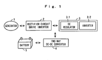
- Fig. 1 is a block diagram showing a concept of a power generating device according to the present invention.
- a generator 1 comprises, for example, a three-phase multipolar magnet generator.
- the generator 1 is connected to an engine, is an engine generator driven by the engine, and is a dual-purpose generator both for a generator function and for an electric motor function, which can be also operated as an engine starting electric motor.
- a rectifier circuit 2 comprising a bridged rectifying element rectifies the output of the generator 1. Moreover, switching elements such as field effect transistors (FETs) are connected in parallel with each rectifying element in the rectifier circuit 2. These switching elements form a drive inverter by which a DC voltage is converted into a three-phase AC voltage by ON - OFF control of the switching elements for application to the generator 1.
- the rectifying elements forming the rectifier circuit 2 may be a parasitic diode of the switching elements such as FET, or a joint diode which is separately connected.
- An electronic power inverter section 3 comprises a DC regulator 3-1 and an inverter 3-2, and converts the output of the rectifier circuit 2 into AC power of a predetermined frequency for output.
- the regulator 3-1 in the electronic power inverter section 3 is not necessarily required, it is possible not to exert effects of fluctuations in the output of a two-way DC-DC converter 4 to an inverter 3-2.
- the voltage of a battery 5 is step upped, and the step-upped voltage is output to the output side of the rectifier circuit 2. Moreover, when the output of the rectifier circuit 2 is enough and a remaining quantity of the battery 5 is small, the battery 5 is charged by supplying the output of the rectifier circuit 2 to the battery 5.
- the side of the battery 5 and that of a rectifier circuit 2 in the DC-DC converter 4 will be called as a primary side, and a secondary side, respectively.
- the battery 5 is, for example, a 12 V battery which has been generally used for a self starter.
- the DC voltage of the battery 5 which has been step-upped in the two-way DC-DC converter 4 according to relative difference in the voltage between the primary side and the secondary side caused by the turns ratio of the transformer of the two-way DC-DC converter 4, is applied to the drive inverter (rectifier circuit) 2.
- TheDC voltage is converted into a three-phase AC voltage by switching driving of the drive inverter 2, based on a starting command, and is applied to the generator 1.
- the generator 1 is started as an engine starting electric motor.
- the generator 1 When the engine is started, the generator 1 is driven by the engine to stop the switching operation of the drive inverter 2.
- the output of the generator 1 is rectified through the rectifier circuit (as a drive inverter) 2, is regulated through the DC regulator 3-1 in the electronic power inverter section 3, and is converted into AC power of a predetermined frequency in the inverter 3-2 for output.
- the battery 5 Since the two-way converter 4 is connected to the output side of the rectifier circuit 2, the battery 5 is automatically charged by the output of the rectifier circuit 2 through the two-way DC-DC converter 4, if the remaining quantity of the battery 5 is small at this time. That is, if the conversion output voltage of the battery is lower than the output voltage of the rectifier circuit 2, power conversion is executed in such a way that the battery 5 is charged with the output of the rectifier circuit 2, based on relative difference in the voltage between the primary side and the secondary side caused by the turns ratio of the transformer of the two-way DC-DC converter 4.
- Fig. 2 is a circuit diagram showing a circuit realizing one embodiment of the power generating device according to the present invention, and the same parts as or parts similar to those previously described with reference to Fig. 1 are denoted by the same reference numbers as those in Fig. 1.
- the three-phase generator 1 is connected to an engine (not shown).
- the output side of the generator 1 is connected to the drive inverter.
- the drive inverter has a configuration in which, for example, six switching elements (hereinafter, called as FETs), such as FETs, 2-1 through 2-6 are bridged.
- Rectifying elements such as a diode are connected in parallel with each FET 2-1 through 2-6.
- the rectifying elements may be a parasitic diode of FETs, or a joint diode which is separately connected, and the rectifier circuit 2 comprises the rectifying elements.
- the output side of the rectifier circuit 2 is connected to the electronic power inverter section 3 comprising the DC regulator 3-1 and the inverter 3-2.
- the DC regulator 3-1 includes, for example, a FET, a choke coil, a capacitor, a diode, and the like, and the inverter 3-2 has a configuration in which, for example, four FETs 3-2-1 through 3-2-4 are bridged.
- a node between the rectifier circuit 2 and the electronic power inverter section 3 is connected to the secondary side of the two-way DC-DC converter 4 and the primary side of the DC-DC converter 4 is connected to the battery 5 comprising, for example, a battery (12 V).
- the two-way DC-DC converter 4 is provided for two-way exchange of electric power between the output of the battery 5 and that of the rectifier circuit 2, and comprises a transformer 4-1 provided with a winding wire 4-1-1 for the low-voltage side as the primary side and a winding wire 4-1-2 for the high-voltage side as the secondary side.
- the step-up voltage ratio of the two-way DC-DC converter 4 is defined by the turns ratio between the winding wire 4-1-1 for the low-voltage side and the winding wire 4-1-2 for the high-voltage side.
- a switching section 4-2 for the lower voltage side and a switching section 4-3 for the higher voltage side are provided on the side of the winding wire 4-1-1 for the low-voltage side and the side of the winding wire 4-1-2 for the high-voltage side, respectively.
- the switching section 4-2 for the lower voltage side has a configuration in which, for example, four FETs 4-2-1 through 4-2-4 are bridged, and, similarly, the switching section 4-3 for the higher voltage side comprises four FETs 4-3-1 through 4-3-4.
- Rectifying elements such as a diode are connected in parallel with each FET 4-2-1 through 4-2-4, and 4-3-1 through 4-3-4 in the switching section 4-2 for the lower voltage side and the switching section 4-3 for the higher voltage side, respectively.
- the rectifying elements may be a parasitic diode of FETs, or a joint diode which is separately connected. Assuming that the rectifying elements which have been connected in parallel could be treated as one unit, the switching section 4-2 for the lower voltage side and the switching section 4-3 for the higher voltage side could be considered to be a switching and rectifying section, respectively.
- An LC resonant circuit 4-4 is provided on the side of the winding wire 4-1-2 for the high-voltage side of the transformer 4-1.
- An LC resonant circuit 4-4 has a function by which a current which flows when at least one of the switching section 4-2 for the lower voltage side and the switching section 4-3 for the higher voltage side is driven is changed to a sinusoidal current, and switching losses are reduced, and destruction of FETs by a large current are prevented. The reason is that ON - OFF control of FETs can be executed approximately at a point crossing the zero level of the sinusoidal current.
- the LC resonant circuit 4-4 may be provided not on the secondary side, but on the primary side.
- Switching control of FETs 4-2-1 through 4-2-4 in the switching section 4-2 for the lower voltage side and FETs 4-3-1 through 4-3-4 in the switching section 4-3 for the higher voltage side is executed by a control circuit (not shown) comprising a CPU and the like.
- capacitors 6, 7 connected to the primary side and the secondary side, respectively, are a capacitor for output smoothing.
- the switching section 4-2 for the lower voltage side and the switching section 4-3 for the higher voltage side are driven in full synchronization with each other, that is, by the same drive signal.
- this driving is executed by alternate ON - OFF control between a pair of FET 4-2-1 and FET 4-2-4, and a pair of FET 4-2-2 and FET 4-2-3 in the switching section 4-2 for the lower voltage side, and by alternate ON - OFF control between a pair of FET 4-3-1 and FET 4-3-4, and a pair of FET 4-3-2 and FET 4-3-3 in the switching section 4-3 for the higher voltage side.
- the generator 1 When the engine is started, the generator 1 is driven by the engine to generate the output.
- the output of the generator 1 is rectified in the rectifier circuit (the drive inverter) 2.
- FETs 2-1 through 2-6 which form the drive inverter, are not driven, and full-wave rectification of the output of the generator 1 is executed with the rectifying elements in the rectifier circuit 2.
- the output of the rectifier circuit 2 is rectified and smoothed by the DC regulator 3-1, and is converted into AC power of a predetermined frequency in the inverter 3-2 for output.
- Driving of the DC regulator for is executed by PWM driving of, for example, FETs.
- the two-way DC-DC converter 4 is driven, when the engine is started, for example, in such a way that one-way power conversion from the primary side to the secondary side is executed.
- the battery 5 can be kept in a preferable state.
- the remaining quantity of the battery 5 can be judged by a value of internal resistance estimated from the temperature and the current of the battery 5, or by an electromotive voltage estimated from fluctuations in the current and the voltage.
- two-way power conversion from the primary side to the secondary side, or from the secondary side to the primary side can be suitably configured to be executed not by driving the switching section 4-2 for the lower voltage side and the switching section 4-3 for the higher voltage side in full synchronization with each other, but by selective driving of the sections.
- electric power can be supplied from the battery 5 to the load for assisting the generator when the overloaded state is caused and the output of the generator 1 cannot meet the demand for the load in the state.
- the present invention is not limited to the engine generator, and is also applied to a common generator in which the output of the common generator is assisted by a battery to meet the demand for overloaded conditions.
- the switching elements are not required to be connected in parallel with the rectifying elements in the rectifier circuit 2, and the rectifier circuit 2 is required only to rectify the output of the generator 1.
- two-way exchange of the electric power between the output of a rectifier circuit and that of a battery through a two-way DC-DC converter is executed, depending on the voltage on the output side of the rectifier circuit. That is, it is possible automatically to replenish deficiency by electric power from the battery when the output of the rectifier circuit is reduced in an overloaded state, and it is possible automatically to charge the battery when the output of the rectifier circuit is enough.
Abstract
Description
- The present invention relates to a power generating device, and more particularly, to a power generating device in which it is possible to replenish the deficiency by electric power from a battery when the output of the power generating device such as an engine generator becomes insufficient.
- A power generating device such as an engine generator has diffused intowidespreadpractice as a power supply device for various kinds of uses such as portable use and emergency one. When a load by which a large electric current temporarily flows when a load of a mercury lamp, that of an electric motor, and the like are started is connected to a relatively small power generating device such as an engine generator, an overloaded state is temporarily occurred and the engine speed and the rotation speed of the generator are reduced to cause a stall (engine stall), in some cases. That is, when the overloaded state is temporarily occurred, the engine speed is reduced to cause reduction in the output of the power generating device by the reduction to cause a further overloaded state. Then, the vicious cycle causes a stall.
- In order to solve the above problem, there has been made an proposal by which the load is limited within a range, in which the engine can be kept at an operation state at the maximum output, to eliminate the overloaded state as soon as possible. There has been disclosed, for example, in the Japanese Patent Publication No. 2740567, an engine speed control device, in which an engine is controlled by reduction in a load to be kept at an operation state at, approximately, the maximum output, when it is not determined that the engine speed is not increased at a rate of a predetermined value or more though it is determined that a feed rate of fuel to the engine is approximately the maximum.
- As described in the above-described patent publication, effective use of the maximum output of the engine can be realized by limiting the load within a range in which the engine can be kept at an operation state at the maximum output. However, since this results in that the output is temporarily limited, shortage of electric power temporarily occurs from a viewpoint of the load side, which is not preferable for the load.
- The object of the present invention is to provide a power generating device which can meet the demand for output shortage even when an overloaded state is temporarily occurred.
- In order to accomplish the object, a first aspect of the present invention is a power generating device comprising a generator, a rectifier circuit which rectifies the output of the generator, and an inverter which converts the output of the rectifier circuit into AC power of a predetermined frequency for output, wherein a two-way DC-DC converter is provided between the output side of the rectifier circuit and the output terminal of a battery.
- A second aspect of the present invention is the power generating device, wherein a regulator is provided between the rectifier circuit and the inverter, and the two-wayDC-DC converter is connectedbetween a node between the rectifier circuit and the regulator, and the output terminal of the battery.
- A third aspect of the present invention is the power generating device, wherein the two-way DC-DC converter comprises: a terminal for a low-voltage side; a terminal for a high-voltage side; a transformer including a winding wire for the low-voltage side and a winding wire for the high-voltage side; a switching element for the low-voltage side inserted between the terminal for the low-voltage side and the winding wire for the low-voltage side; a switching element for the high-voltage side inserted between the terminal for the high-voltage side and the winding wire for the high-voltage side; a rectifying element for the low-voltage side connected in parallel with the switching element for the low-voltage side; a rectifying element for the high-voltage side connected in parallel with the switching element for the high-voltage side, and a control circuit which controls the switching element for the low-voltage side and the switching element for the high-voltage side, and two-way exchange of electric power between the output of the battery and that of the rectifier circuit by simultaneous driving of the switching element for the low-voltage side and the switching element for the high-voltage side.
- A fourth aspect of the present invention is the power generating device, wherein the device has a configuration in which, while monitoring the charged state of the battery, driving of the switching element for the higher voltage side is stopped when it is determined that the battery is in an overloaded state.
- A fifth aspect of the present invention is the power generating device, wherein the device has a configuration in which, while monitoring the output voltage of the rectifier circuit, driving of the switching element for the lower voltage side is started when it is determined that the output voltage is reduced to a value smaller than a predetermined value.
- According to the first aspect of the present invention, two-way exchange of electric power between the output of a rectifier circuit and that of a battery through a two-way DC-DC converter is executed, depending on the voltage on the output side of the rectifier circuit. That is, it is possible to supply deficiency by electric power from the battery when the output of the rectifier circuit is reduced in an overloaded state, and it is possible to charge the battery when the output of the rectifier circuit is enough.
- Moreover, according to a second aspect of the present invention, it is possible to realize stable operation of an inverter, because fluctuations in the output of the two-way DC-DC converter is absorbed by a regulator between the rectifier and the inverter, and it is possible not to exert effects of the fluctuations in the output to the inverter.
- Furthermore, according to a third aspect of the present invention, a simple configuration of the two-way DC-DC converter can be realized.
- Moreover, according to a fourth aspect of the present invention, the reliability of the device can be improved, and it is possible to prolong the life of the battery, because the battery can be kept in a preferable state by preventing an overloaded or an over-discharged state of the battery.
- In addition, according to a fifth aspect of the present invention, supply of electric power from the battery can be started when the output of the generator cannot meet the demand for the load.
-
- Fig. 1 is a block diagram showing a concept of a power generating device according to the present invention.
- Fig. 2 is a circuit diagram showing a circuit realizing one embodiment of the power generating device according to the present invention.
-
- Hereinafter, the present invention will be explained in detail referring to drawings. Fig. 1 is a block diagram showing a concept of a power generating device according to the present invention. In the drawing, a generator 1 comprises, for example, a three-phase multipolar magnet generator. In the following embodiments, explanation will be made on the assumption that the generator 1 is connected to an engine, is an engine generator driven by the engine, and is a dual-purpose generator both for a generator function and for an electric motor function, which can be also operated as an engine starting electric motor.
- A
rectifier circuit 2 comprising a bridged rectifying element rectifies the output of the generator 1. Moreover, switching elements such as field effect transistors (FETs) are connected in parallel with each rectifying element in therectifier circuit 2. These switching elements form a drive inverter by which a DC voltage is converted into a three-phase AC voltage by ON - OFF control of the switching elements for application to the generator 1. Here, the rectifying elements forming therectifier circuit 2 may be a parasitic diode of the switching elements such as FET, or a joint diode which is separately connected. - An electronic
power inverter section 3 comprises a DC regulator 3-1 and an inverter 3-2, and converts the output of therectifier circuit 2 into AC power of a predetermined frequency for output. Here, though the regulator 3-1 in the electronicpower inverter section 3 is not necessarily required, it is possible not to exert effects of fluctuations in the output of a two-way DC-DC converter 4 to an inverter 3-2. - In the two-
way converter 4, the voltage of abattery 5 is step upped, and the step-upped voltage is output to the output side of therectifier circuit 2. Moreover, when the output of therectifier circuit 2 is enough and a remaining quantity of thebattery 5 is small, thebattery 5 is charged by supplying the output of therectifier circuit 2 to thebattery 5. Hereinafter, the side of thebattery 5 and that of arectifier circuit 2 in the DC-DC converter 4 will be called as a primary side, and a secondary side, respectively. Thebattery 5 is, for example, a 12 V battery which has been generally used for a self starter. - Then, operations in Fig. 1 will be explained. The primary side and the secondary side of the two-way DC-
DC converter 4 are driven in full synchronization with each other, that is, by the same drive signal. By this driving mode, automatic two-way power conversion is executed as described below in the two-way DC-DC converter 4. - When the engine is started, the DC voltage of the
battery 5, which has been step-upped in the two-way DC-DC converter 4 according to relative difference in the voltage between the primary side and the secondary side caused by the turns ratio of the transformer of the two-way DC-DC converter 4, is applied to the drive inverter (rectifier circuit) 2. TheDC voltage is converted into a three-phase AC voltage by switching driving of thedrive inverter 2, based on a starting command, and is applied to the generator 1. Thereby, the generator 1 is started as an engine starting electric motor. - When the engine is started, the generator 1 is driven by the engine to stop the switching operation of the
drive inverter 2. The output of the generator 1 is rectified through the rectifier circuit (as a drive inverter) 2, is regulated through the DC regulator 3-1 in the electronicpower inverter section 3, and is converted into AC power of a predetermined frequency in the inverter 3-2 for output. - In the case of no overloaded state, enough output is obtained from the
rectifier circuit 2, and electric power is supplied to the load only by the generator 1. At this time electric power is not supplied from thebattery 5 through the two-way DC-DC converter 4. - Since the two-
way converter 4 is connected to the output side of therectifier circuit 2, thebattery 5 is automatically charged by the output of therectifier circuit 2 through the two-way DC-DC converter 4, if the remaining quantity of thebattery 5 is small at this time. That is, if the conversion output voltage of the battery is lower than the output voltage of therectifier circuit 2, power conversion is executed in such a way that thebattery 5 is charged with the output of therectifier circuit 2, based on relative difference in the voltage between the primary side and the secondary side caused by the turns ratio of the transformer of the two-way DC-DC converter 4. - When the overloaded state is caused and the output of the generator 1 cannot meet the demand for the load in the state, the output of the
rectifier circuit 2 is reduced. Along with the reduction in the output, automatic power conversion from the primary side to the secondary side of the two-wayDC-DC converter 4 is executed to cause a state in which electric power is supplied to the load from thebattery 5. Accordingly, the conversion output of thebattery 5 is superimposed onto that of the generator 1. That is, electric power is supplied to the load in the mode in which the generator 1 is assisted by thebattery 5. Moreover, when the generator 1 is stopped for any reason, electric power is automatically supplied to the load only from thebattery 5 through the two-way DC-DC converter 4 and the electronicpower inverter section 3. - Fig. 2 is a circuit diagram showing a circuit realizing one embodiment of the power generating device according to the present invention, and the same parts as or parts similar to those previously described with reference to Fig. 1 are denoted by the same reference numbers as those in Fig. 1. The three-phase generator 1 is connected to an engine (not shown). The output side of the generator 1 is connected to the drive inverter. The drive inverter has a configuration in which, for example, six switching elements (hereinafter, called as FETs), such as FETs, 2-1 through 2-6 are bridged.
- Rectifying elements such as a diode are connected in parallel with each FET 2-1 through 2-6. The rectifying elements may be a parasitic diode of FETs, or a joint diode which is separately connected, and the
rectifier circuit 2 comprises the rectifying elements. - The output side of the
rectifier circuit 2 is connected to the electronicpower inverter section 3 comprising the DC regulator 3-1 and the inverter 3-2. The DC regulator 3-1 includes, for example, a FET, a choke coil, a capacitor, a diode, and the like, and the inverter 3-2 has a configuration in which, for example, four FETs 3-2-1 through 3-2-4 are bridged. - A node between the
rectifier circuit 2 and the electronicpower inverter section 3 is connected to the secondary side of the two-way DC-DC converter 4 and the primary side of the DC-DC converter 4 is connected to thebattery 5 comprising, for example, a battery (12 V). - The two-way DC-
DC converter 4 is provided for two-way exchange of electric power between the output of thebattery 5 and that of therectifier circuit 2, and comprises a transformer 4-1 provided with a winding wire 4-1-1 for the low-voltage side as the primary side and a winding wire 4-1-2 for the high-voltage side as the secondary side. The step-up voltage ratio of the two-way DC-DC converter 4 is defined by the turns ratio between the winding wire 4-1-1 for the low-voltage side and the winding wire 4-1-2 for the high-voltage side. - A switching section 4-2 for the lower voltage side and a switching section 4-3 for the higher voltage side are provided on the side of the winding wire 4-1-1 for the low-voltage side and the side of the winding wire 4-1-2 for the high-voltage side, respectively. The switching section 4-2 for the lower voltage side has a configuration in which, for example, four FETs 4-2-1 through 4-2-4 are bridged, and, similarly, the switching section 4-3 for the higher voltage side comprises four FETs 4-3-1 through 4-3-4.
- Rectifying elements such as a diode are connected in parallel with each FET 4-2-1 through 4-2-4, and 4-3-1 through 4-3-4 in the switching section 4-2 for the lower voltage side and the switching section 4-3 for the higher voltage side, respectively. The rectifying elements may be a parasitic diode of FETs, or a joint diode which is separately connected. Assuming that the rectifying elements which have been connected in parallel could be treated as one unit, the switching section 4-2 for the lower voltage side and the switching section 4-3 for the higher voltage side could be considered to be a switching and rectifying section, respectively.
- An LC resonant circuit 4-4 is provided on the side of the winding wire 4-1-2 for the high-voltage side of the transformer 4-1. An LC resonant circuit 4-4 has a function by which a current which flows when at least one of the switching section 4-2 for the lower voltage side and the switching section 4-3 for the higher voltage side is driven is changed to a sinusoidal current, and switching losses are reduced, and destruction of FETs by a large current are prevented. The reason is that ON - OFF control of FETs can be executed approximately at a point crossing the zero level of the sinusoidal current. Here, the LC resonant circuit 4-4 may be provided not on the secondary side, but on the primary side.
- Switching control of FETs 4-2-1 through 4-2-4 in the switching section 4-2 for the lower voltage side and FETs 4-3-1 through 4-3-4 in the switching section 4-3 for the higher voltage side is executed by a control circuit (not shown) comprising a CPU and the like. Here, capacitors 6, 7 connected to the primary side and the secondary side, respectively, are a capacitor for output smoothing.
- Then, operations in Fig. 2 will be explained. In order to execute automatic two-way power conversion in the two-way DC-
DC converter 4, the switching section 4-2 for the lower voltage side and the switching section 4-3 for the higher voltage side are driven in full synchronization with each other, that is, by the same drive signal. As is commonly known, this driving is executed by alternate ON - OFF control between a pair of FET 4-2-1 and FET 4-2-4, and a pair of FET 4-2-2 and FET 4-2-3 in the switching section 4-2 for the lower voltage side, and by alternate ON - OFF control between a pair of FET 4-3-1 and FET 4-3-4, and a pair of FET 4-3-2 and FET 4-3-3 in the switching section 4-3 for the higher voltage side. - When the engine is started, power conversion from the primary side to the secondary side of the two-way DC-
DC converter 4 is executed, and the DC voltage of thebattery 5, which has been step-upped by the above conversion is applied to the drive inverter (rectifier circuit) 2. By thedrive inverter 2, the DC voltage is converted into a three-phase AC voltage, and is applied to the generator 1. Thereby, the generator 1 is started as an engine starting electric motor. This driving is executed by pulse-width-modulation (PWM) driving of FETs 2-1 through 2-6 in the drive inverter. At this time, phase discrimination is executed by using changes in the current distribution caused by a counter-electromotive voltage according to the operation of the generator (electric motor) 1 to execute sensor-less synchronous driving. - When the engine is started, the generator 1 is driven by the engine to generate the output. The output of the generator 1 is rectified in the rectifier circuit (the drive inverter) 2. At this time, FETs 2-1 through 2-6, which form the drive inverter, are not driven, and full-wave rectification of the output of the generator 1 is executed with the rectifying elements in the
rectifier circuit 2. The output of therectifier circuit 2 is rectified and smoothed by the DC regulator 3-1, and is converted into AC power of a predetermined frequency in the inverter 3-2 for output. Driving of the DC regulator for is executed by PWM driving of, for example, FETs. - If the remaining quantity of the
battery 5 is small at this time, power conversion from the secondary side to the primary side is executed in the two-way DC-DC converter 4, and thebattery 5 is charged by the reduced output of therectifier circuit 3. Moreover, when the overloaded state is caused and the output of the generator 1 cannot meet the demand for the load in the state, power conversion is executed in such a way that electric power is also supplied from thebattery 5 through the two-way DC-DC converter 4. - Thus, automatic power exchange between the primary side and the secondary side is executed in the two-way DC-
DC converter 4 according to relative difference in the voltage between the primary side and the secondary side caused by the turns ratio of the transformer 4-1, and two-way exchange of the electric power between both the sides is executed. - Though the embodiments have been explained as described above, various kinds of changes and modifications could be made.
Sufficiently, the two-way DC-DC converter 4 is driven, when the engine is started, for example, in such a way that one-way power conversion from the primary side to the secondary side is executed. - Moreover, according to one configuration, while monitoring the charged state of the
battery 5 based on the battery voltage and the battery current, driving of the switching section 4-3 for the higher voltage side is stopped when it is determined that the battery is in an overloaded state, and driving of the switching section 4-2 for the lower voltage side is stopped when it is determined that the battery is in an over-discharged state. Thereby, thebattery 5 can be kept in a preferable state. Here, the remaining quantity of thebattery 5 can be judged by a value of internal resistance estimated from the temperature and the current of thebattery 5, or by an electromotive voltage estimated from fluctuations in the current and the voltage. - Moreover, two-way power conversion from the primary side to the secondary side, or from the secondary side to the primary side can be suitably configured to be executed not by driving the switching section 4-2 for the lower voltage side and the switching section 4-3 for the higher voltage side in full synchronization with each other, but by selective driving of the sections.
- There can be a configuration, for example, in which, while monitoring the output voltage of the
rectifier circuit 2, driving of the switching section 4-2 for the lower voltage side is started when it is determined that the output voltage is reduced to a value smaller than a predetermined value. According to the above configuration, electric power can be supplied from thebattery 5 to the load for assisting the generator when the overloaded state is caused and the output of the generator 1 cannot meet the demand for the load in the state. - Furthermore, the present invention is not limited to the engine generator, and is also applied to a common generator in which the output of the common generator is assisted by a battery to meet the demand for overloaded conditions. In this case, the switching elements are not required to be connected in parallel with the rectifying elements in the
rectifier circuit 2, and therectifier circuit 2 is required only to rectify the output of the generator 1. - As explained in detail above, according to the present invention, two-way exchange of the electric power between the output of a rectifier circuit and that of a battery through a two-way DC-DC converter is executed, depending on the voltage on the output side of the rectifier circuit. That is, it is possible automatically to replenish deficiency by electric power from the battery when the output of the rectifier circuit is reduced in an overloaded state, and it is possible automatically to charge the battery when the output of the rectifier circuit is enough.
- Moreover, according to a configuration in which, while monitoring the output of the rectifier circuit and that of thebattery, driving control of the two-way DC-DC converter is executed, depending on the monitoring results, it is possible to meet the demand for overloaded conditions, and, also, the battery can be kept in a preferable state by preventing an overloaded or an over-discharged state of the battery.
Claims (5)
- A power generating device comprising a generator (1), a rectifier circuit (2) which rectifies the output of the generator (1), and an inverter (3-2) which converts the output of the rectifier circuit (2) into AC power of a predetermined frequency for output, wherein
a two-way DC-DC converter (4) is provided between the output side of the rectifier circuit (2) and the output terminal of a battery (5). - The power generating device according to claim 1, wherein a regulator (3-1) is provided between the rectifier circuit (2) and the inverter (3-2), and
the two-way DC-DC converter (4) is connected between a node between the rectifier circuit (2) and the regulator (3-1), and the output terminal of the battery (5). - The power generating device according to claim 2, wherein
the two-way DC-DC converter (4) comprises: a terminal for a low-voltage side; a terminal for a high-voltage side; a transformer (4-1) including a winding wire (4-1-1) for the low-voltage side and a winding wire (4-1-2) for the high-voltage side; a switching element (4-2-1 through 4-2-4) for the low-voltage side inserted between the terminal for the low-voltage side and the winding wire (4-1-1) for the low-voltage side; a switching element (4-3-1 through 4-3-4) for the high-voltage side inserted between the terminal for the high-voltage side and the winding wire (4-1-2) for the high-voltage side; a rectifying element for the low-voltage side connected in parallel with the switching element (4-2-1 through 4-2-4) for the low-voltage side; a rectifying element for the high-voltage side connected in parallel with the switching element (4-3-1 through 4-3-4) for the high-voltage side, and a control circuit which controls the switching element (4-2-1 through 4-2-4) for the low-voltage side and the switching element (4-3-1 through 4-3-4) for the high-voltage side, and
two-way exchange of electric power between the output of the battery (5) and that of the rectifier circuit (2) by simultaneous driving of the switching element (4-2-1 through 4-2-4) for the low-voltage side and the switching element (4-3-1 through 4-3-4) for the high-voltage side. - The power generating device according to claim 3, wherein the device has a configuration in which, while monitoring the charged state of the battery (5), driving of the switching element (4-3-1 through 4-3-4) for the higher voltage side is stopped when it is determined that the battery (5) is in an overloaded state.
- The power generating device according to claim 3, wherein the device has a configuration in which, while monitoring the output voltage of the rectifier circuit, driving of the switching element (4-2-1 through 4-2-4) for the lower voltage side is started when it is determined that the output voltage is reduced to a value smaller than a predetermined value.
Applications Claiming Priority (2)
| Application Number | Priority Date | Filing Date | Title |
|---|---|---|---|
| JP2003067966A JP2004282827A (en) | 2003-03-13 | 2003-03-13 | Generator |
| JP2003067966 | 2003-03-13 |
Publications (3)
| Publication Number | Publication Date |
|---|---|
| EP1463178A2 true EP1463178A2 (en) | 2004-09-29 |
| EP1463178A3 EP1463178A3 (en) | 2005-05-25 |
| EP1463178B1 EP1463178B1 (en) | 2008-06-25 |
Family
ID=32821262
Family Applications (1)
| Application Number | Title | Priority Date | Filing Date |
|---|---|---|---|
| EP04005655A Expired - Fee Related EP1463178B1 (en) | 2003-03-13 | 2004-03-10 | Power generating device |
Country Status (7)
| Country | Link |
|---|---|
| US (1) | US20040178773A1 (en) |
| EP (1) | EP1463178B1 (en) |
| JP (1) | JP2004282827A (en) |
| KR (1) | KR20040081376A (en) |
| CN (1) | CN1531189A (en) |
| DE (1) | DE602004014551D1 (en) |
| TW (1) | TW200507439A (en) |
Cited By (2)
| Publication number | Priority date | Publication date | Assignee | Title |
|---|---|---|---|---|
| EP1976092A1 (en) * | 2007-03-30 | 2008-10-01 | ABB Technology Ltd | A power supply device |
| GB2508098A (en) * | 2012-11-16 | 2014-05-21 | Torch Solar Technologies Ltd | Power management system with increased generator efficiency |
Families Citing this family (29)
| Publication number | Priority date | Publication date | Assignee | Title |
|---|---|---|---|---|
| CA2470934C (en) * | 2002-01-16 | 2008-04-22 | Toyota Jidosha Kabushiki Kaisha | An apparatus and method for controlling a voltage converter |
| US20110121653A1 (en) * | 2005-02-18 | 2011-05-26 | O2Micro International Limited | Parallel powering of portable electrical devices |
| US7719236B2 (en) * | 2005-02-18 | 2010-05-18 | O2Micro International Limited | Parallel powering of portable electrical devices |
| EP2348626A3 (en) * | 2005-07-29 | 2017-04-19 | TDK Corporation | Switching power supply with surge voltage suppression |
| CN100450813C (en) * | 2005-11-30 | 2009-01-14 | 上海大郡自动化系统工程有限公司 | Symmetrically arranged power source for electric vehicles and its motor driving system |
| US7508086B2 (en) * | 2006-03-24 | 2009-03-24 | General Electric Company | Aircraft engine starter/generator and controller |
| US7439715B2 (en) * | 2006-05-22 | 2008-10-21 | Hamilton Sundstrand Corporation | Dual source power generating system |
| CN100563086C (en) * | 2006-10-16 | 2009-11-25 | 盈正豫顺电子股份有限公司 | Active bi-directional electric power adjuster |
| DE112008000378T5 (en) * | 2007-02-16 | 2009-12-31 | Komatsu Ltd. | A generator drive apparatus, hybrid vehicle and control method for the generator drive apparatus |
| JP2009027886A (en) * | 2007-07-23 | 2009-02-05 | Sanken Electric Co Ltd | Ac-dc converter |
| JP5381005B2 (en) * | 2008-10-16 | 2014-01-08 | 富士電機株式会社 | Power conversion system |
| JP2010124549A (en) * | 2008-11-17 | 2010-06-03 | Toshiba Corp | Movable body |
| JP2011200095A (en) * | 2010-02-26 | 2011-10-06 | Sanyo Electric Co Ltd | Battery system |
| JP5449014B2 (en) * | 2010-05-07 | 2014-03-19 | 本田技研工業株式会社 | Automatic start / stop device for generator |
| CN102655351A (en) * | 2011-03-02 | 2012-09-05 | 江苏嘉钰新能源技术有限公司 | Direct-current high-pressure two-way DC/DC (direct current) convertor energy storage device |
| JP5778445B2 (en) | 2011-03-11 | 2015-09-16 | 東芝機械株式会社 | Inverter power generator |
| JP5488505B2 (en) * | 2011-03-16 | 2014-05-14 | 株式会社ダイフク | Contactless power supply equipment |
| US8994214B2 (en) * | 2011-08-09 | 2015-03-31 | Bae Systems Controls Inc. | Hybrid electric generator set |
| CN103161640A (en) * | 2011-12-16 | 2013-06-19 | 哈米尔顿森德斯特兰德公司 | System and method relating to electric start and power generation |
| CN102536482B (en) * | 2012-03-02 | 2013-12-18 | 北京理工大学 | Generating system |
| CN103312025A (en) * | 2012-03-12 | 2013-09-18 | 北京倍肯恒业科技发展有限责任公司 | Intelligent power supply control system |
| JP5959289B2 (en) | 2012-04-23 | 2016-08-02 | 株式会社東芝 | Battery system |
| DE102012207809A1 (en) * | 2012-05-10 | 2013-11-14 | Robert Bosch Gmbh | Range extender, drive and motor vehicle |
| CN102710006B (en) * | 2012-05-18 | 2014-12-24 | 深圳市健网科技有限公司 | Double-power supply system with balance bridge arm |
| US9859752B2 (en) * | 2015-06-05 | 2018-01-02 | General Electric Company | Uninterruptible power supply and method of use |
| CN108092371B (en) * | 2016-11-15 | 2020-04-03 | 华为技术有限公司 | Charging and discharging device |
| CN106870238B (en) * | 2017-04-18 | 2019-03-29 | 苏州半唐电子有限公司 | A kind of digital electricity generating system |
| CN106870236B (en) * | 2017-04-18 | 2018-10-30 | 苏州半唐电子有限公司 | A kind of digital electricity generating system unit starting accumulator plant |
| CN112042074A (en) * | 2018-03-29 | 2020-12-04 | 本田技研工业株式会社 | Output control device for hybrid engine generator |
Citations (2)
| Publication number | Priority date | Publication date | Assignee | Title |
|---|---|---|---|---|
| US4709318A (en) * | 1986-10-22 | 1987-11-24 | Liebert Corporation | UPS apparatus with control protocols |
| EP1289113A2 (en) * | 2001-08-31 | 2003-03-05 | Denso Corporation | Automotive alternator having detector for detecting initiation of rotation |
Family Cites Families (5)
| Publication number | Priority date | Publication date | Assignee | Title |
|---|---|---|---|---|
| US5602462A (en) * | 1995-02-21 | 1997-02-11 | Best Power Technology, Incorporated | Uninterruptible power system |
| US6184593B1 (en) * | 1999-07-29 | 2001-02-06 | Abb Power T&D Company Inc. | Uninterruptible power supply |
| US6624533B1 (en) * | 1999-08-04 | 2003-09-23 | Westerbeke Corporation | Controlling generator power |
| DE10149827A1 (en) * | 2001-10-09 | 2003-04-30 | Siemens Ag | Stabilizing circuit has one switched mode supply stage output connected to one supply voltage pole, load coupled to other switched mode supply stage output and to other supply pole |
| JP2003259508A (en) * | 2002-02-26 | 2003-09-12 | Sanyo Electric Co Ltd | Power unit for electric vehicle |
-
2003
- 2003-03-13 JP JP2003067966A patent/JP2004282827A/en active Pending
-
2004
- 2004-02-26 US US10/785,962 patent/US20040178773A1/en not_active Abandoned
- 2004-03-02 TW TW093105335A patent/TW200507439A/en unknown
- 2004-03-10 EP EP04005655A patent/EP1463178B1/en not_active Expired - Fee Related
- 2004-03-10 DE DE602004014551T patent/DE602004014551D1/en not_active Expired - Lifetime
- 2004-03-12 CN CNA2004100086085A patent/CN1531189A/en active Pending
- 2004-03-12 KR KR1020040016787A patent/KR20040081376A/en not_active Application Discontinuation
Patent Citations (2)
| Publication number | Priority date | Publication date | Assignee | Title |
|---|---|---|---|---|
| US4709318A (en) * | 1986-10-22 | 1987-11-24 | Liebert Corporation | UPS apparatus with control protocols |
| EP1289113A2 (en) * | 2001-08-31 | 2003-03-05 | Denso Corporation | Automotive alternator having detector for detecting initiation of rotation |
Cited By (2)
| Publication number | Priority date | Publication date | Assignee | Title |
|---|---|---|---|---|
| EP1976092A1 (en) * | 2007-03-30 | 2008-10-01 | ABB Technology Ltd | A power supply device |
| GB2508098A (en) * | 2012-11-16 | 2014-05-21 | Torch Solar Technologies Ltd | Power management system with increased generator efficiency |
Also Published As
| Publication number | Publication date |
|---|---|
| JP2004282827A (en) | 2004-10-07 |
| TW200507439A (en) | 2005-02-16 |
| DE602004014551D1 (en) | 2008-08-07 |
| US20040178773A1 (en) | 2004-09-16 |
| EP1463178A3 (en) | 2005-05-25 |
| EP1463178B1 (en) | 2008-06-25 |
| KR20040081376A (en) | 2004-09-21 |
| CN1531189A (en) | 2004-09-22 |
Similar Documents
| Publication | Publication Date | Title |
|---|---|---|
| EP1463178B1 (en) | Power generating device | |
| EP1562273A2 (en) | Power supply apparatus | |
| US6989655B2 (en) | Engine generator | |
| EP1667309A1 (en) | Power supply device | |
| US7830680B2 (en) | Power unit | |
| JP4318174B2 (en) | DC-DC converter | |
| US6456514B1 (en) | Alternator jump charging system | |
| US6151222A (en) | Dual voltage automotive electrical system with sub-resonant DC-DC converter | |
| JP5553677B2 (en) | Output controller for hybrid generator | |
| US8890492B2 (en) | Automatic start/stop device for engine-driven power generator | |
| EP1458084A2 (en) | Two-way DC-DC converter | |
| WO2006027917A1 (en) | Power supply | |
| JP2002165448A (en) | Two-way dc-dc converter | |
| JP2009261186A (en) | Bidirectional dc/dc converter and power conditioner | |
| JPH118910A (en) | Power supply equipment for hybrid electric vehicle | |
| JP2000050402A (en) | Power source unit for hybrid electric automobile | |
| JP4553292B2 (en) | Power supply | |
| JP4191874B2 (en) | Uninterruptible power system | |
| JP2006101636A (en) | Power supply | |
| JP2000050404A (en) | Power source unit for hybrid electric automobile | |
| JP2010252604A (en) | Controller of load driving system | |
| JP2004208389A (en) | Dc-dc converter improved in power factor and electronic apparatus using the same |
Legal Events
| Date | Code | Title | Description |
|---|---|---|---|
| PUAI | Public reference made under article 153(3) epc to a published international application that has entered the european phase |
Free format text: ORIGINAL CODE: 0009012 |
|
| AK | Designated contracting states |
Kind code of ref document: A2 Designated state(s): AT BE BG CH CY CZ DE DK EE ES FI FR GB GR HU IE IT LI LU MC NL PL PT RO SE SI SK TR |
|
| AX | Request for extension of the european patent |
Extension state: AL LT LV MK |
|
| PUAL | Search report despatched |
Free format text: ORIGINAL CODE: 0009013 |
|
| AK | Designated contracting states |
Kind code of ref document: A3 Designated state(s): AT BE BG CH CY CZ DE DK EE ES FI FR GB GR HU IE IT LI LU MC NL PL PT RO SE SI SK TR |
|
| AX | Request for extension of the european patent |
Extension state: AL LT LV MK |
|
| RIC1 | Information provided on ipc code assigned before grant |
Ipc: 7H 02J 9/00 A |
|
| 17P | Request for examination filed |
Effective date: 20050524 |
|
| AKX | Designation fees paid |
Designated state(s): DE FR GB IT |
|
| GRAP | Despatch of communication of intention to grant a patent |
Free format text: ORIGINAL CODE: EPIDOSNIGR1 |
|
| GRAS | Grant fee paid |
Free format text: ORIGINAL CODE: EPIDOSNIGR3 |
|
| GRAA | (expected) grant |
Free format text: ORIGINAL CODE: 0009210 |
|
| AK | Designated contracting states |
Kind code of ref document: B1 Designated state(s): DE FR GB IT |
|
| REG | Reference to a national code |
Ref country code: GB Ref legal event code: FG4D |
|
| REF | Corresponds to: |
Ref document number: 602004014551 Country of ref document: DE Date of ref document: 20080807 Kind code of ref document: P |
|
| PLBE | No opposition filed within time limit |
Free format text: ORIGINAL CODE: 0009261 |
|
| STAA | Information on the status of an ep patent application or granted ep patent |
Free format text: STATUS: NO OPPOSITION FILED WITHIN TIME LIMIT |
|
| 26N | No opposition filed |
Effective date: 20090326 |
|
| PGFP | Annual fee paid to national office [announced via postgrant information from national office to epo] |
Ref country code: IT Payment date: 20110321 Year of fee payment: 8 Ref country code: FR Payment date: 20110317 Year of fee payment: 8 |
|
| PGFP | Annual fee paid to national office [announced via postgrant information from national office to epo] |
Ref country code: GB Payment date: 20110309 Year of fee payment: 8 Ref country code: DE Payment date: 20110302 Year of fee payment: 8 |
|
| GBPC | Gb: european patent ceased through non-payment of renewal fee |
Effective date: 20120310 |
|
| REG | Reference to a national code |
Ref country code: FR Ref legal event code: ST Effective date: 20121130 |
|
| PG25 | Lapsed in a contracting state [announced via postgrant information from national office to epo] |
Ref country code: GB Free format text: LAPSE BECAUSE OF NON-PAYMENT OF DUE FEES Effective date: 20120310 Ref country code: FR Free format text: LAPSE BECAUSE OF NON-PAYMENT OF DUE FEES Effective date: 20120402 |
|
| REG | Reference to a national code |
Ref country code: DE Ref legal event code: R119 Ref document number: 602004014551 Country of ref document: DE Effective date: 20121002 |
|
| PG25 | Lapsed in a contracting state [announced via postgrant information from national office to epo] |
Ref country code: IT Free format text: LAPSE BECAUSE OF NON-PAYMENT OF DUE FEES Effective date: 20120310 |
|
| PG25 | Lapsed in a contracting state [announced via postgrant information from national office to epo] |
Ref country code: DE Free format text: LAPSE BECAUSE OF NON-PAYMENT OF DUE FEES Effective date: 20121002 |