EP1179671A2 - Method for checking a fuel injection system - Google Patents
Method for checking a fuel injection system Download PDFInfo
- Publication number
- EP1179671A2 EP1179671A2 EP01117710A EP01117710A EP1179671A2 EP 1179671 A2 EP1179671 A2 EP 1179671A2 EP 01117710 A EP01117710 A EP 01117710A EP 01117710 A EP01117710 A EP 01117710A EP 1179671 A2 EP1179671 A2 EP 1179671A2
- Authority
- EP
- European Patent Office
- Prior art keywords
- intake manifold
- manifold pressure
- diagnosis
- valve
- internal combustion
- Prior art date
- Legal status (The legal status is an assumption and is not a legal conclusion. Google has not performed a legal analysis and makes no representation as to the accuracy of the status listed.)
- Granted
Links
Images


Classifications
-
- F—MECHANICAL ENGINEERING; LIGHTING; HEATING; WEAPONS; BLASTING
- F02—COMBUSTION ENGINES; HOT-GAS OR COMBUSTION-PRODUCT ENGINE PLANTS
- F02D—CONTROLLING COMBUSTION ENGINES
- F02D41/00—Electrical control of supply of combustible mixture or its constituents
- F02D41/22—Safety or indicating devices for abnormal conditions
- F02D41/222—Safety or indicating devices for abnormal conditions relating to the failure of sensors or parameter detection devices
-
- F—MECHANICAL ENGINEERING; LIGHTING; HEATING; WEAPONS; BLASTING
- F02—COMBUSTION ENGINES; HOT-GAS OR COMBUSTION-PRODUCT ENGINE PLANTS
- F02D—CONTROLLING COMBUSTION ENGINES
- F02D41/00—Electrical control of supply of combustible mixture or its constituents
- F02D41/0025—Controlling engines characterised by use of non-liquid fuels, pluralities of fuels, or non-fuel substances added to the combustible mixtures
- F02D41/003—Adding fuel vapours, e.g. drawn from engine fuel reservoir
- F02D41/0032—Controlling the purging of the canister as a function of the engine operating conditions
- F02D41/0035—Controlling the purging of the canister as a function of the engine operating conditions to achieve a special effect, e.g. to warm up the catalyst
- F02D41/0037—Controlling the purging of the canister as a function of the engine operating conditions to achieve a special effect, e.g. to warm up the catalyst for diagnosing the engine
-
- F—MECHANICAL ENGINEERING; LIGHTING; HEATING; WEAPONS; BLASTING
- F02—COMBUSTION ENGINES; HOT-GAS OR COMBUSTION-PRODUCT ENGINE PLANTS
- F02D—CONTROLLING COMBUSTION ENGINES
- F02D41/00—Electrical control of supply of combustible mixture or its constituents
- F02D41/0025—Controlling engines characterised by use of non-liquid fuels, pluralities of fuels, or non-fuel substances added to the combustible mixtures
- F02D41/0047—Controlling exhaust gas recirculation [EGR]
- F02D41/005—Controlling exhaust gas recirculation [EGR] according to engine operating conditions
- F02D41/0055—Special engine operating conditions, e.g. for regeneration of exhaust gas treatment apparatus
-
- F—MECHANICAL ENGINEERING; LIGHTING; HEATING; WEAPONS; BLASTING
- F02—COMBUSTION ENGINES; HOT-GAS OR COMBUSTION-PRODUCT ENGINE PLANTS
- F02D—CONTROLLING COMBUSTION ENGINES
- F02D41/00—Electrical control of supply of combustible mixture or its constituents
- F02D41/02—Circuit arrangements for generating control signals
- F02D41/14—Introducing closed-loop corrections
- F02D41/1401—Introducing closed-loop corrections characterised by the control or regulation method
- F02D2041/1413—Controller structures or design
- F02D2041/1432—Controller structures or design the system including a filter, e.g. a low pass or high pass filter
-
- F—MECHANICAL ENGINEERING; LIGHTING; HEATING; WEAPONS; BLASTING
- F02—COMBUSTION ENGINES; HOT-GAS OR COMBUSTION-PRODUCT ENGINE PLANTS
- F02D—CONTROLLING COMBUSTION ENGINES
- F02D2200/00—Input parameters for engine control
- F02D2200/02—Input parameters for engine control the parameters being related to the engine
- F02D2200/04—Engine intake system parameters
- F02D2200/0406—Intake manifold pressure
-
- Y—GENERAL TAGGING OF NEW TECHNOLOGICAL DEVELOPMENTS; GENERAL TAGGING OF CROSS-SECTIONAL TECHNOLOGIES SPANNING OVER SEVERAL SECTIONS OF THE IPC; TECHNICAL SUBJECTS COVERED BY FORMER USPC CROSS-REFERENCE ART COLLECTIONS [XRACs] AND DIGESTS
- Y02—TECHNOLOGIES OR APPLICATIONS FOR MITIGATION OR ADAPTATION AGAINST CLIMATE CHANGE
- Y02T—CLIMATE CHANGE MITIGATION TECHNOLOGIES RELATED TO TRANSPORTATION
- Y02T10/00—Road transport of goods or passengers
- Y02T10/10—Internal combustion engine [ICE] based vehicles
- Y02T10/40—Engine management systems
Definitions
- the invention relates to a method for checking a fuel injection system the features mentioned in the preamble of claim 1.
- the use of fuel injection systems to form mixtures is known by means of which the fuel is fed into combustion air.
- Systems for external mixture formation and systems for internal mixture formation distinguished, with fuel injection centrally in an intake manifold for all cylinders the internal combustion engine or decentrally for each of the cylinders of the Internal combustion engine can be done.
- the fuel injection systems use one Pressure difference between a fuel pressure and an intake manifold pressure. According to a release of a fuel injection valve and a defined one The pressure difference between the fuel and the combustion air results in the amount of fuel injected. It becomes clear that to set this defined Pressure difference and thus to define a defined control of a Injector knowledge of the current intake manifold pressure is required. This directly affects mixture formation.
- Is known in an intake manifold To arrange internal combustion engine at least one intake manifold pressure sensor, whose sensor output signal to an engine control unit for further processing Is made available.
- DE 32 26 849 A1 describes a device for monitoring a pressure sensor known in which a signal comparison of a measurement signal of the pressure sensor to a known physical state of the suction system is carried out. This can a physically impossible pressure signal can be detected.
- the disadvantage here is that only a rough statement about the function or non-function of the pressure sensor can be hit.
- the invention has for its object to a method of the generic type create a review of a fuel injection system in a simple and safe manner is possible.
- this object is achieved by a method with the method described in claim 1 mentioned features solved.
- a sensor signal Intake manifold pressure sensor with a control signal of the intake manifold pressure influencing adjusting means is cross-correlated and a correlation coefficient as Diagnostic signal of the intake manifold pressure sensor is evaluated, is a very advantageous get accurate and safe diagnostic result, in addition to the general Function monitoring also a qualitative statement about that from The intake manifold pressure sensor allows the measurement signal supplied.
- Correlation procedure for the determination the similarity of two curves, here the sensor signal from Intake manifold pressure sensor and the control signal of the intake manifold pressure influencing actuators are considered reliable and easy to use Process known. These procedures have no relevant influence on the correlated measurement variables, so that an influence on the operation of the fuel injection system and thus not given to the entire internal combustion engine is. An additional outlay on equipment for carrying out the invention Procedure is also not required.
- control signal a control signal influencing the intake manifold pressure
- a control signal for a Throttle valve a control signal of an exhaust gas recirculation valve and / or a Control signal of a tank ventilation valve
- These control signals are known to be provided by the engine control unit and are therefore available usual equipment of motor vehicles for the invention Correlation calculation available. Especially when the cross correlation is through a Engine control unit of the motor vehicle is carried out, the control signals in be tapped easily.
- Figure 1 shows schematically an internal combustion engine 10. Der Internal combustion engine 10 is an intake system 12 and an exhaust system 14 assigned.
- the exhaust system 14 includes at least one exhaust duct 16 that leads to leads to an exhaust outlet 18. At least one, not here, can be in the exhaust duct 16 catalyst device shown may be integrated.
- the suction system 12 comprises a suction pipe 20, by means of which a source 22 Vacuum combustion air of the internal combustion engine can be supplied.
- the Combustion air supply can be regulated with a throttle valve 24.
- the exhaust duct 16 is connected to the intake manifold 20 via a connecting line 26, in which an exhaust gas recirculation valve 28 is integrated. In the exhaust duct 16 is also a Lambda probe 30 integrated. Suction system 12 includes an air mass sensor 32 and an intake manifold pressure sensor 34.
- the internal combustion engine 10 is also assigned a tank ventilation system 36.
- the tank ventilation system 36 comprises a connecting line 38 that connects a tank 40 connects to the suction system 12.
- the connecting line 38 opens into the Intake pipe 20.
- a tank ventilation valve 42 is integrated in the connecting line 38.
- the filter device 46 is, for example, an activated carbon container 48 within which a bed of activated carbon 50 is arranged. From one of the activated carbon 50 downstream collecting space 52 leads a connection 54 to the outside.
- the tank ventilation valve 42, the intake manifold pressure sensor 34, the air mass sensor 32, the throttle valve 24, the exhaust gas recirculation valve 28 and the lambda probe 30 via measurement lines or control lines indicated here with a Engine control unit 56 connected.
- the internal combustion engine 10 is also a fuel injection system 58 assigned four injection valves 60 according to the exemplary embodiment shown here comprises, in the connecting lines 62 of the suction pipe 20 to the individual Cylinders 64 of the internal combustion engine 10 open.
- the injection valves 60 are included a fuel supply 66 and also connected via the engine control unit 56 in controllable in a known manner.
- a combustion air is supplied through the suction system 12, which is under a certain pressure p1.
- the amount of combustion air supplied can be determined by the throttle valve 24 built into the intake system 12 can be integrated.
- the Fuel in the fuel supply 66 at a pressure p2, which is activated by driving Fuel pressure control systems (not shown in FIG. 1) can be set.
- This Pressure p2 of the fuel is set so that a defined pressure difference between the pressure p2 of the fuel and the pressure p1 of the combustion air given is.
- the injection valves 60 are open, there is therefore a pressure difference between the pressure p2 and the pressure p1, which over the opening time of the Injectors 60 the amount of fuel supplied to the combustion process certainly.
- This fuel-air mixture is generated within the Internal combustion engine 10 burned.
- the exhaust gas generated during the combustion process is via the Exhaust system 14 cleaned and removed. Should the combustion air be a subset of the Exhaust gas are supplied, the exhaust gas recirculation valve 28 via the Engine control unit 56 controlled.
- the exhaust gas recirculation valve 28 is, for example, a electromagnetic proportional valve.
- About the control of the Exhaust gas recirculation valve 28 may be the amount of that supplied to the combustion air Exhaust gas can be adjusted.
- the amount of exhaust gas returned over time To be able to set, is a pressure difference between the pressure p1 Combustion air in the intake manifold 20 and a pressure p3 of the exhaust gas, respectively the resulting pressure difference is important.
- a pressure p4 in tank 40 and generally an ambient pressure Internal combustion engine p5. If the pressure p4 in the tank 40 rises above the Ambient pressure p5 occurs via the connecting line 38 and the connection 44 and the filter device 46 a venting of the tank 40. Should a cleaning of the Filter device 46 take place, the tank ventilation valve 42 is opened. Hereby lies the intake manifold pressure p1 at the tank 40 and the filter device 46. Since the Intake manifold pressure p1 is lower than the pressure p4 and the pressure p5 results in Pressure drop through which the fuel vapors from the tank 40 and those in the Activated carbon 50 stored fuel vapors over the open Tank ventilation valve 42 sucked and the combustion air Internal combustion engine 10 are supplied.
- the method according to the invention for checking the Intake manifold pressure sensor 34 explained.
- the test procedure initialized (field 72).
- a query 74 is then used to check whether Release conditions 76 for the examination procedure are given.
- the Release conditions 76 include, for example, those running in parallel Control processes or parallel diagnostic procedures of other facilities of the motor vehicle, which could be influenced by the test procedure.
- the signal 78 is stimulated Test procedure in which an adjusting means influencing the intake manifold pressure p1 for example, the tank vent valve 42, the throttle valve 24, the Exhaust gas recirculation valve 28 is stimulated by the current control signal this positioning means is superimposed as a test pattern.
- the test pattern consists of individual Impulses, their sequence, duration and / or amplitude the properties of the Internal combustion engine 10 or the intake manifold 20 is adapted.
- Test patterns 80 so-called pseudorandom pulse trains are used. The The amplitude of the test pattern 80 is chosen so small that there is an impairment the operation of the internal combustion engine 10 can be avoided.
- test pattern 80 becomes the sensor signal 68 of the intake manifold pressure sensor 34 recorded.
- the test pattern 80 and the sensor signal 68 become one Cross correlation 82 supplied. Before the cross-correlation 82 is carried out, as in FIG. 3 shows that the test pattern 80 is preprocessed.
- a signal 84 results in a Repetition test 86 triggered.
- the number of carried out Measuring cycles compared with a predefinable number. Is the number of performed Measuring cycles smaller than the predetermined number, the signal 88 Repeat test triggered.
- the cross correlation 82 is thus quasi new stimulated. Is the number of measurement cycles carried out equal to the specified one? Number, a diagnosis 92 is carried out via a signal 90.
- diagnosis 92 checks a correlation coefficient of the correlation calculation 82 carried out. has this correlation coefficient has a value close to 1, the test patterns are 80 and the sensor signal 68 is identical in the sense of the correlation calculation.
- Correlation coefficient on the other hand, has a value close to 0, there is none Relationship between the test pattern 80 and the sensor signal 68, so that on an error 94 is detected.
- the number of Retry Checks 86 determine an average correlation factor associated with a Error threshold is compared. If the error threshold is exceeded, this means that the test pattern 80 is in the intake manifold pressure p1, that is to say the sensor signal 68, finds. This means that the function of the intake manifold pressure sensor 34 is flawless. If the error falls below the error threshold, error message 94 is ejected. at A driver can recognize the fault 94, for example, by means of an optical one Signal is given information that the intake manifold pressure sensor 34 is faulty is. Furthermore, the fault 94 can be stored in the engine control unit 56, so that A corresponding note is issued when the next maintenance diagnosis is made.
- a termination 96 of the examination procedure takes place, for example, when the examination of the Release conditions 76 via a signal 98 has shown that the necessary defined release conditions 76 are not given. Furthermore, during the Stimulation of the cross correlation 82 a signal 100 are generated, which is also used for Abort 96 leads.
- the signal 100 may, for example, be an error signal that is at missing or implausible measured variable 68 (sensor signal 68), expiry of an intended Total service life of the intake manifold pressure sensor 34 and / or when the predetermined number of measurement cycles to be carried out during the Repeat check 86 is generated.
- a timer can be started that runs through the exam process Reinitialization 72 starts again. If necessary, it can be provided that the Test procedure expires with each restart of the internal combustion engine 10.
- the cross correlation can be carried out passively or - as explained - actively.
- the passive cross-correlation is the signals to be evaluated, here the Control signal of the exhaust gas recirculation valve 28, the throttle valve 24 or the Tank vent valve 42 and the measurement size 68, processed unaffected.
- the Active cross-correlation described are those that enter the cross-correlation Control signals excited with stimulation signals, so that a sensitivity of the Examination procedure can be increased.
- This stimulation consists in the described overlay with the test pattern 80, which consists of individual pulses exists, the sequence, duration and amplitude of which correspond to the properties of the Internal combustion engine 10 or the intake manifold 20 are adapted.
- the amplitudes of the Test pattern 80 due to the high sensitivity of the cross-correlation calculation 82 be kept as small as possible with a relevant influence on speed and / or torque of the internal combustion engine 10 is not to be expected.
- FIG Release conditions 76 clarifies.
- the release conditions 76 are in one Query 102 linked to blocks of release conditions.
- Figure 3 are schematic two blocks 104 and 106 of release conditions respectively defined Operating conditions of different internal combustion engines 10 shown.
- Block 104 is an internal combustion engine with intake manifold injection and the Block 106 of an internal combustion engine with direct fuel injection assigned.
- Boundary conditions are different release conditions respectively Defined operating parameters during the implementation of the on the basis of Figure 2 explained diagnostic procedure required. Compliance with the release conditions or the achievement of the defined operating parameters is indicated by a Signal 108 to the release condition check 76 acknowledged. Only when this Acknowledgment signal 108 is present, the actual diagnosis of the intake manifold pressure sensor 34 in released as explained.
- additional release conditions are also defined.
- Operating conditions of the internal combustion engine 10 in direct fuel injectors are defined. This is necessary because there are a number of other direct fuel injection systems Actuators are present that can influence intake manifold pressure.
- Actuators are present that can influence intake manifold pressure.
- Direct fuel injection in different operating modes, especially one Shift operation or homogeneous operation, which can also be operated by a clearly different level of the intake manifold pressure, especially by one clearly differing regulation of the intake manifold pressure.
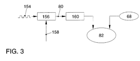
- FIG. 3 illustrates the implementation of the cross correlation 82 in a block diagram between the test pattern 80 and the measurement variable 68.
- the control signal 154 of the Actuator (tank ventilation valve 42, throttle valve 24, exhaust gas recirculation valve 28), a signal module 156 that is to be overlaid with the test pattern fed.
- the signal 154 is superimposed with a pseudorandom signal 158, see above that the test pattern 80 is obtained.
- the test pattern 80 is over a Low pass filter 160 performed, which comprises a PT1 element. This ensures that the Ideally, the signal curve of the test pattern 80 is the signal curve of the measured variable 68 (at the assumption that no faults occur) is identical.
- the slope of the signal 154 is adapted to the slope of the measured variable 68.
- the edges of the measurement variable 68 point first for the so-called delay elements Order typical waveforms of an e-function.
- This e-function is supported by the Low-pass filter 160 modeled for the test pattern 80, so that the subsequent Cross correlation 82 leads to large correlation coefficients (against 1). This will the accuracy of cross correlation increases.
Abstract
Description
Die Erfindung betrifft ein Verfahren zum Überprüfen eines Kraftstoff-Einspritzsystems mit den im Oberbegriff des Anspruchs 1 genannten Merkmalen.The invention relates to a method for checking a fuel injection system the features mentioned in the preamble of claim 1.
Es ist bekannt, dass eine Verbrennungskraftmaschine (Otto-Motor) zu ihrem Betrieb ein Kraftstoff-Luft-Gemisch benötigt. Von einem Kraftstoff-Luft-Verhältnis innerhalb dieses Gemisches ist der Betrieb der Verbrennungskraftmaschine im Wesentlichen abhängig. Hierdurch ergibt sich beispielsweise ein Kraftstoffverbrauch, eine Leistungsbereitstellung (Drehmoment) und/oder eine Abgasnachbehandlungsmöglichkeit der Verbrennungskraftmaschine. Entsprechend gewünschter Betriebsmodi der Verbrennungskraftmaschine erfolgt bekannterweise eine Veränderung des Mischungsverhältnisses innerhalb des Kraftstoff-Luft-Gemisches.It is known that an internal combustion engine (Otto engine) is used to operate it Air-fuel mixture required. A fuel-air ratio within this Mixture, the operation of the internal combustion engine is essentially dependent. This results in, for example, fuel consumption and provision of power (Torque) and / or an exhaust gas aftertreatment option Internal combustion engine. According to the desired operating modes Internal combustion engine is known to change the Mixing ratio within the fuel-air mixture.
Zur Gemischbildung ist der Einsatz von Kraftstoff-Einspritzsystemen bekannt, mittels denen der Kraftstoff in eine Verbrennungsluft zugeführt wird. Hier wird zwischen Systemen zur äußeren Gemischbildung und Systemen zur inneren Gemischbildung unterschieden, wobei die Kraftstoffeinspritzung zentral in ein Saugrohr für alle Zylinder der Verbrennungskraftmaschine oder dezentral für jeden der Zylinder der Verbrennungskraftmaschine erfolgen kann. Die Kraftstoff-Einspritzsysteme nutzen eine Druckdifferenz zwischen einem Kraftstoffdruck und einem Saugrohrdruck aus. Entsprechend einer Freigabe eines Kraftstoff-Einspritzventils und einer definierten Druckdifferenz zwischen dem Kraftstoff und der Verbrennungsluft ergibt sich die eingespritzte Kraftstoffmenge. Es wird deutlich, dass zum Einstellen dieser definierten Druckdifferenz und somit zum Festlegen einer definierten Ansteuerung eines Einspritzventils Kenntnisse über den aktuellen Saugrohrdruck erforderlich sind. Dieser beeinflusst unmittelbar die Gemischbildung. Bekannt ist, in einem Saugrohr der Verbrennungskraftmaschine wenigstens einen Saugrohrdrucksensor anzuordnen, dessen Sensorausgangssignal einem Motorsteuergerät zur weiteren Verarbeitung zur Verfügung gestellt wird. The use of fuel injection systems to form mixtures is known by means of which the fuel is fed into combustion air. Here is between Systems for external mixture formation and systems for internal mixture formation distinguished, with fuel injection centrally in an intake manifold for all cylinders the internal combustion engine or decentrally for each of the cylinders of the Internal combustion engine can be done. The fuel injection systems use one Pressure difference between a fuel pressure and an intake manifold pressure. According to a release of a fuel injection valve and a defined one The pressure difference between the fuel and the combustion air results in the amount of fuel injected. It becomes clear that to set this defined Pressure difference and thus to define a defined control of a Injector knowledge of the current intake manifold pressure is required. This directly affects mixture formation. Is known in an intake manifold To arrange internal combustion engine at least one intake manifold pressure sensor, whose sensor output signal to an engine control unit for further processing Is made available.
Es wird deutlich, dass schon geringe Saugrohrdruckänderungen zu einer veränderten Gemischbildung beitragen können. Derartige Saugrohrdruckänderungen können auch ungewollt und/oder nur scheinbar sein. Beispielsweise bei einer alterungsbedingten Änderung einer Sensorkennlinie des Saugrohrdrucksensors ergeben sich Abweichungen im Sensorausgangssignal von dem tatsächlichen Ist-Saugrohrdruck. Durch diesen entsprechenden Fehler ergibt sich eine fehlerbehaftete Auswertung im Motorsteuergerät, so dass negative Auswirkungen auf die Gemischbildung nicht auszuschließen sind.It becomes clear that even small changes in the intake manifold pressure have changed Mixture formation can contribute. Such changes in intake manifold pressure can also to be unwanted and / or only apparent. For example, with an age-related one Changes to a sensor characteristic of the intake manifold pressure sensor result in deviations in the sensor output signal from the actual intake manifold pressure. Through this corresponding errors, there is a faulty evaluation in the engine control unit, so that negative effects on mixture formation cannot be ruled out.
Aus der DE 32 26 849 A1 ist eine Vorrichtung zum Überwachen eines Drucksensors bekannt, bei der ein Signalvergleich eines Messsignals des Drucksensors zu einem bekannten physikalischen Zustand der Sauganlage durchgeführt wird. Hierdurch kann ein physikalisch unmögliches Drucksignal erkannt werden. Nachteilig hierbei ist, dass nur eine grobe Aussage über die Funktion beziehungsweise Nichtfunktion des Drucksensors getroffen werden kann.DE 32 26 849 A1 describes a device for monitoring a pressure sensor known in which a signal comparison of a measurement signal of the pressure sensor to a known physical state of the suction system is carried out. This can a physically impossible pressure signal can be detected. The disadvantage here is that only a rough statement about the function or non-function of the pressure sensor can be hit.
Aus der DE 198 44 086 A1 ist eine Einrichtung zum Steuern einer Brennkraftmaschine bekannt, mittels der zum genauen Ermitteln eines Saugrohrdrucks ein dynamisches Modell der Sauganlage verwendet wird. Dies erfordert einen erheblichen Aufwand und lässt Fehler der an der Modellrechnung beteiligten Ausgangsinformationen, beispielsweise Messgrößen einer Drehzahl beziehungsweise Öffnungsgrad einer Drosselklappe, unberücksichtigt.DE 198 44 086 A1 describes a device for controlling an internal combustion engine known, by means of which for the precise determination of an intake manifold pressure a dynamic Model of the suction system is used. This requires considerable effort and leaves errors in the initial information involved in the model calculation, For example, measured variables of a speed or degree of opening of one Throttle valve, disregarded.
Der Erfindung liegt die Aufgabe zugrunde, ein Verfahren der gattungsgemäßen Art zu schaffen, mit dem in einfacher und sicherer Weise eine Überprüfung eines Kraftstoff-Einspritzsystems möglich ist.The invention has for its object to a method of the generic type create a review of a fuel injection system in a simple and safe manner is possible.
Erfindungsgemäß wird diese Aufgabe durch ein Verfahren mit den im Anspruch 1 genannten Merkmalen gelöst. Dadurch, dass ein Sensorsignal eines Saugrohrdrucksensors mit einem Ansteuersignal eines den Saugrohrdruck beeinflussenden Stellmittels kreuzkorreliert wird und ein Korrelationskoeffizient als Diagnosesignal des Saugrohrdrucksensors ausgewertet wird, wird vorteilhaft ein sehr genaues und sicheres Diagnoseergebnis erhalten, das neben der allgemeinen Funktionsüberwachung auch eine qualitative Aussage über das vom Saugrohrdrucksensor gelieferte Messsignal zulässt. Korrelationsverfahren zur Ermittlung der Ähnlichkeit zweier Kurvenverläufe, hier des Sensorsignals des Saugrohrdrucksensors und des Ansteuersignals eines den Saugrohrdruck beeinflussenden Stellmittels, sind als zuverlässige und einfach zu handhabende Verfahren bekannt. Diese Verfahren üben keinen relevanten Einfluss auf die zu korrelierenden Messgrößen aus, so dass ein Einfluss auf den Betrieb des Kraftstoff-Einspritzsystems und somit auf die gesamte Verbrennungskraftmaschine nicht gegeben ist. Ein zusätzlicher apparativer Aufwand zur Durchführung des erfindungsgemäßen Verfahren ist ferner nicht erforderlich.According to the invention, this object is achieved by a method with the method described in claim 1 mentioned features solved. The fact that a sensor signal Intake manifold pressure sensor with a control signal of the intake manifold pressure influencing adjusting means is cross-correlated and a correlation coefficient as Diagnostic signal of the intake manifold pressure sensor is evaluated, is a very advantageous get accurate and safe diagnostic result, in addition to the general Function monitoring also a qualitative statement about that from The intake manifold pressure sensor allows the measurement signal supplied. Correlation procedure for the determination the similarity of two curves, here the sensor signal from Intake manifold pressure sensor and the control signal of the intake manifold pressure influencing actuators are considered reliable and easy to use Process known. These procedures have no relevant influence on the correlated measurement variables, so that an influence on the operation of the fuel injection system and thus not given to the entire internal combustion engine is. An additional outlay on equipment for carrying out the invention Procedure is also not required.
In bevorzugter Ausgestaltung der Erfindung ist vorgesehen, dass als Ansteuersignal eines den Saugrohrdruck beeinflussenden Stellmittels ein Ansteuersignal für eine Drosselklappe, ein Ansteuersignal eines Abgasrückführungsventils und/oder ein Ansteuersignal eines Tankentlüftungsventils verwendet wird. Diese Ansteuersignale werden vom Motorsteuergerät bekanntermaßen bereitgestellt und stehen somit bei üblichen Ausstattungen von Kraftfahrzeugen für die erfindungsgemäße Korrelationsrechnung zur Verfügung. Insbesondere, wenn die Kreuzkorrelation durch ein Motorsteuergerät des Kraftfahrzeuges durchgeführt wird, können die Ansteuersignale in einfacher Weise abgegriffen werden.In a preferred embodiment of the invention it is provided that as a control signal a control signal influencing the intake manifold pressure, a control signal for a Throttle valve, a control signal of an exhaust gas recirculation valve and / or a Control signal of a tank ventilation valve is used. These control signals are known to be provided by the engine control unit and are therefore available usual equipment of motor vehicles for the invention Correlation calculation available. Especially when the cross correlation is through a Engine control unit of the motor vehicle is carried out, the control signals in be tapped easily.
In weiterer bevorzugter Ausgestaltung der Erfindung ist vorgesehen, dass vor Durchführung der Kreuzkorrelation Freigabebedingungen für das Prüfverfahren überprüft werden. Hierdurch wird eine Zuverlässigkeit der Überprüfung des Saugrohrdrucksensors weiter erhöht. Insbesondere wird hierdurch sichergestellt, dass für die Kreuzkorrelation mit dem Sensorsignal herangezogene Ansteuersignale von den Saugrohrdruck beeinflussenden Stellmitteln nicht durch eine zum Zeitpunkt der Kreuzkorrelation gerade vorgenommene Änderung der Ansteuersignale beeinflusst sind. Hierdurch werden ungewollte Einflüsse auf ein Betriebsmanagement der Verbrennungskraftmaschine durch die Kreuzkorrelation verhindert. Ferner wird hierdurch die Genauigkeit und Zuverlässigkeit des Diagnoseverfahrens insgesamt wesentlich erhöht.In a further preferred embodiment of the invention, it is provided that Carrying out the cross-correlation. Approval conditions for the test procedure checked become. This will make the intake manifold pressure sensor reliable further increased. In particular, this ensures that for the cross-correlation with the sensor signal used control signals from the intake manifold pressure influencing adjusting means not by a straight at the time of cross-correlation changes made to the control signals are influenced. This will unwanted influences on the operational management of the internal combustion engine prevents cross correlation. Furthermore, the accuracy and Overall, the reliability of the diagnostic procedure increased significantly.
Weitere bevorzugte Ausgestaltungen der Erfindung ergeben sich aus den übrigen, in den Unteransprüchen genannten Merkmalen.Further preferred refinements of the invention result from the others in the Characteristics mentioned subclaims.
Die Erfindung wird nachfolgend in einem Ausführungsbeispiel anhand der zugehörigen Zeichnungen näher erläutert. Es zeigen:
- Figur 1
- eine schematische Ansicht einer Verbrennungskraftmaschine;
- Figur 2
- ein Blockschaltbild für die Durchführung eines Verfahrens zum Prüfen eines Messsignales eines Saugrohrdrucksensors;
- Figur 2a
- ein Blockschaltbild für die Festlegung von Freigabebedingungen für das Prüfverfahren und
- Figur 3
- ein Blockschaltbild für die Durchführung der Kreuzkorrelation zwischen einem Testmuster und dem Sensorsignal.
- Figure 1
- a schematic view of an internal combustion engine;
- Figure 2
- a block diagram for performing a method for testing a measurement signal of an intake manifold pressure sensor;
- Figure 2a
- a block diagram for the definition of release conditions for the test method and
- Figure 3
- a block diagram for performing the cross-correlation between a test pattern and the sensor signal.
Figur 1 zeigt schematisch eine Verbrennungskraftmaschine 10. Der
Verbrennungskraftmaschine 10 ist eine Sauganlage 12 und eine Abgasanlage 14
zugeordnet. Die Abgasanlage 14 umfasst wenigstens einen Abgaskanal 16, der zu
einem Abgasauslass 18 führt. In dem Abgaskanal 16 kann wenigstens eine, hier nicht
dargestellte Katalysatoreinrichtung integriert sein.Figure 1 shows schematically an
Die Sauganlage 12 umfasst ein Saugrohr 20, über das von einer Quelle 22 mittels
Unterdruck eine Verbrennungsluft der Verbrennungskraftmaschine zuführbar ist. Die
Verbrennungsluftzufuhr ist mit einer Drosselklappe 24 regelbar.The
Der Abgaskanal 16 ist mit dem Saugrohr 20 über eine Verbindungsleitung 26 verbunden,
in die ein Abgasrückführungsventil 28 integriert ist. In den Abgaskanal 16 ist ferner eine
Lambdasonde 30 integriert. Die Sauganlage 12 umfasst einen Luftmassensensor 32
sowie einen Saugrohrdrucksensor 34.The
Der Verbrennungskraftmaschine 10 ist ferner ein Tankentlüftungssystem 36 zugeordnet.
Das Tankentlüftungssystem 36 umfasst eine Verbindungsleitung 38, die einen Tank 40
mit der Sauganlage 12 verbindet. Die Verbindungsleitung 38 mündet hierbei in das
Saugrohr 20. In die Verbindungsleitung 38 ist ein Tankentlüftungsventil 42 integriert. Von
der Verbindungsleitung 26 zweigt ferner eine Verbindung 44 zu einer Filtereinrichtung 46
ab. Die Filtereinrichtung 46 ist beispielsweise ein Aktivkohlebehälter 48, innerhalb dem
eine Schüttung von Aktivkohle 50 angeordnet ist. Von einem der Aktivkohle 50
nachgeordneten Sammelraum 52 führt eine Verbindung 54 ins Freie. The
Das Tankentlüftungsventil 42, der Saugrohrdrucksensor 34, der Luftmassensensor 32,
die Drosselklappe 24, das Abgasrückführungsventil 28 und die Lambdasonde 30 sind
über hier angedeutete Messleitungen beziehungsweise Steuerleitungen mit einem
Motorsteuergerät 56 verbunden.The
Der Verbrennungskraftmaschine 10 ist ferner ein Kraftstoff-Einspritzsystem 58
zugeordnet, das gemäß dem hier gezeigten Ausführungsbeispiel vier Einspritzventile 60
umfasst, die in Verbindungsleitungen 62 des Saugrohres 20 zu den einzelnen
Zylindern 64 der Verbrennungskraftmaschine 10 münden. Die Einspritzventile 60 sind mit
einer Kraftstoffzuführung 66 verbunden und ebenfalls über das Motorsteuergerät 56 in
bekannter Weise ansteuerbar.The
Aufbau und Wirkungsweise der in Figur 1 gezeigten Verbrennungskraftmaschine 10 sind
allgemein bekannt, so dass hier nur auf die allgemeine Funktion eingegangen werden
soll.The structure and mode of operation of the
Durch die Sauganlage 12 wird eine Verbrennungsluft zugeführt, die unter einem
bestimmten Druck p1 steht. Die Menge der zugeführten Verbrennungsluft kann durch die
in die Sauganlage 12 eingebaute Drosselklappe 24 integriert werden. Ferner steht der
Kraftstoff in der Kraftstoffzuführung 66 unter einem Druck p2, der durch Ansteuerung von
in Figur 1 nicht gezeigten Kraftstoff-Druckregelsystemen eingestellt werden kann. Dieser
Druck p2 des Kraftstoffes wird so eingestellt, dass eine definierte Druckdifferenz
zwischen dem Druck p2 des Kraftstoffes und dem Druck p1 der Verbrennungsluft
gegeben ist. Bei geöffneten Einspritzventilen 60 ergibt sich daher eine Druckdifferenz
zwischen dem Druck p2 und dem Druck p1, die über die Öffnungszeit der
Einspritzventile 60 die den Verbrennungsprozess zugeführte Menge an Kraftstoff
bestimmt. Dieses so erzeugte Kraftstoff-Luft-Gemisch wird innerhalb der
Verbrennungskraftmaschine 10 verbrannt.A combustion air is supplied through the
Das während des Verbrennungsprozesses entstehende Abgas wird über die
Abgasanlage 14 gereinigt und abgeführt. Soll der Verbrennungsluft eine Teilmenge des
Abgases zugeführt werden, wird das Abgasrückführungsventil 28 über das
Motorsteuergerät 56 angesteuert. Das Abgasrückführungsventil 28 ist beispielsweise ein
elektromagnetisches Proportionalventil. Über die Ansteuerung des
Abgasrückführungsventils 28 kann die Menge des der Verbrennungsluft zugeführten
Abgases eingestellt werden. Um die Menge des rückgeführten Abgases über der Zeit
einstellen zu können, ist eine Druckdifferenz zwischen dem Druck p1 der
Verbrennungsluft im Saugrohr 20 und einem Druck p3 des Abgases beziehungsweise
die sich hieraus ergebene Druckdifferenz wichtig.The exhaust gas generated during the combustion process is via the
Ferner herrscht im Tank 40 ein Druck p4 sowie allgemein ein Umgebungsdruck der
Verbrennungskraftmaschine p5. Steigt der Druck p4 im Tank 40 über den
Umgebungsdruck p5 an, erfolgt über die Verbindungsleitung 38 sowie die Verbindung 44
und die Filtereinrichtung 46 eine Entlüftung des Tankes 40. Soll eine Reinigung der
Filtereinrichtung 46 erfolgen, wird das Tankentlüftungsventil 42 geöffnet. Hierdurch liegt
der Saugrohrdruck p1 am Tank 40 und der Filtereinrichtung 46 an. Da der
Saugrohrdruck p1 geringer ist als der Druck p4 und der Druck p5, ergibt sich ein
Druckgefälle, durch das die Kraftstoffdämpfe aus dem Tank 40 und die in der
Aktivkohle 50 gespeicherten Kraftstoffdämpfe über das geöffnete
Tankentlüftungsventil 42 angesaugt und der Verbrennungsluft der
Verbrennungskraftmaschine 10 zugeführt werden.Furthermore, there is a pressure p4 in
Anhand der Erläuterungen wird deutlich, dass dem im Saugrohr 20 herrschenden
Saugrohrdruck p1 für die Einstellung von Betriebsmodi der
Verbrennungskraftmaschine 10 eine erhebliche Bedeutung zukommt. Damit das
Motorsteuergerät 56 sowohl das Kraftstoff-Einspritzsystem 58, die Abgasrückführung
und/oder die Tankentlüftung entsprechend externer Vorgaben, beispielsweise von einem
Kraftfahrzeugführer, und/oder Betriebsbedingungen der Verbrennungskraftmaschine und
einem im Saugrohr 20 herrschenden Saugrohrdruck p1 steuern beziehungsweise regeln
kann, muss eine Genauigkeit des vom Saugrohrdrucksensor 34 gelieferten
Sensorsignales 68 überprüft werden. Mögliche Fehler liegen beispielsweise in
Alterungserscheinungen des Saugrohrdrucksensors 34, die zu Messfehlern - und damit
zu Fehlern des Signales 68 - führen könnten. Ferner können Verunreinigungen der
Verbrennungsluft zu Funktionsbeeinträchtigungen des Saugrohrdrucksensors 34 führen.From the explanations it is clear that the prevailing in the
Anhand der Erläuterung der Funktion der Verbrennungskraftmaschine 10 wird deutlich,
dass Ansteuerungen des Tankentlüftungsventils 42, des Abgasrückführungsventils 28,
der Drosselklappe 24 und/oder Einspritzventile 60 zu einer Beeinflussung des
Saugrohrdruckes p1 führen, da hierdurch Verbindungen zu unter abweichenden
Drücken p2, p3, p4 beziehungsweise p5 stehenden Medien freigegeben werden. The explanation of the function of the
Anhand von Figur 2 wird das erfindungsgemäße Verfahren zum Überprüfen des
Saugrohrdrucksensors 34 erläutert. Bei einem Start 70 des Kraftfahrzeuges,
beispielsweise durch Betätigen des Zündschlosses, wird das Prüfungsverfahren
initialisiert (Feld 72). Anschließend wird über eine Abfrage 74 geprüft, ob
Freigabebedingungen 76 für das Prüfungsverfahren gegeben sind. Auf die
Freigabebedingungen 76 wird anhand von Figur 2a noch näher eingegangen. Die
Freigabebedingungen 76 beinhalten beispielsweise parallel ablaufende
Steuerungsvorgänge oder parallel ablaufende Diagnoseverfahren anderer Einrichtungen
des Kraftfahrzeuges, die durch das Prüfungsverfahren beeinflusst werden könnten.The method according to the invention for checking the
Intake
Sind die Freigabebedingungen 76 erfüllt, erfolgt über ein Signal 78 eine Stimulation des
Prüfungsverfahrens, in dem ein den Saugrohrdruck p1 beeinflussendes Stellmittel,
beispielsweise das Tankentlüftungsventil 42, die Drosselklappe 24, das
Abgasrückführungsventil 28 stimuliert wird, indem dem aktuellen Ansteuersignal eines
dieser Stellmittel als Testmuster überlagert wird. Das Testmuster besteht aus einzelnen
Impulsen, deren Folge, Dauer und/oder Amplitude den Eigenschaften der
Verbrennungskraftmaschine 10 beziehungsweise dem Saugrohr 20 angepasst ist. Als
Testmuster 80 werden sogenannte Pseudorandom-Impulsfolgen verwendet. Die
Amplitude des Testmusters 80 ist hierbei so klein gewählt, dass eine Beeinträchtigung
des Betriebes der Verbrennungskraftmaschine 10 vermieden werden. Während der
Stimulation des Testmusters 80 wird das Sensorsignal 68 des Saugrohrdrucksensors 34
aufgezeichnet. Das Testmuster 80 und das Sensorsignal 68 werden einer
Kreuzkorrelation 82 zugeführt. Vor Durchführung der Kreuzkorrelation 82 kann -wie
Figur 3 zeigt - eine Vorverarbeitung des Testmusters 80 erfolgen.If the
Nach Durchführung der Kreuzkorrelation 82 wird mittels eines Signals 84 eine
Wiederholungsprüfung 86 ausgelöst. Hierbei wird die Anzahl der durchgeführten
Messzyklen mit einer vorgebbaren Anzahl verglichen. Ist die Anzahl der durchgeführten
Messzyklen kleiner als die vorgegebene Zahl, wird über ein Signal 88 die
Wiederholungsprüfung ausgelöst. Die Kreuzkorrelation 82 wird somit quasi neu
stimuliert. Ist die Anzahl der durchgeführten Messzyklen gleich der vorgegebenen
Anzahl, wird über ein Signal 90 eine Diagnose 92 durchgeführt. Bei der Diagnose 92 wird
ein Korrelationskoeffizient der durchgeführten Korrelationsrechnung 82 überprüft. Weist
dieser Korrelationskoeffizient einen Wert von nahe 1 auf, sind das Testmuster 80 und
das Sensorsignal 68 im Sinne der Korrelationsrechnung identisch. Weist der
Korrelationskoeffizient hingegen einen Wert von nahe 0 auf, besteht kein
Zusammenhang zwischen dem Testmuster 80 und dem Sensorsignal 68, so dass auf
einen Fehler 94 erkannt wird. Nach der erreichten Anzahl der
Wiederholungsprüfungen 86 wird ein mittlerer Korrelationsfaktor bestimmt, der mit einem
Fehlerschwellwert vergleichen wird. Wird der Fehlerschwellwert überschritten, heißt dies,
dass das Testmuster 80 sich in dem Saugrohrdruck p1, also dem Sensorsignal 68,
wiederfindet. Dies bedeutet, die Funktion des Saugrohrdrucksensors 34 ist einwandfrei.
Wird der Fehlerschwellwert unterschritten, wird die Fehlermeldung 94 ausgeworfen. Bei
Erkennen des Fehlers 94 kann beispielsweise einem Fahrzeugführer durch ein optisches
Signal eine Information gegeben werden, dass der Saugrohrdrucksensor 34 fehlerhaft
ist. Ferner kann der Fehler 94 im Motorsteuergerät 56 eingespeichert werden, so dass
bei einer nächsten Wartungsdiagnose ein entsprechender Hinweis ergeht.After the
Ein Abbruch 96 des Prüfungsverfahrens findet beispielsweise statt, wenn die Prüfung der
Freigabebedingungen 76 über ein Signal 98 ergeben hat, dass die notwendigen
definierten Freigabebedingungen 76 nicht gegeben sind. Ferner kann während der
Stimulation der Kreuzkorrelation 82 ein Signal 100 generiert werden, das ebenfalls zum
Abbruch 96 führt. Das Signal 100 kann beispielsweise ein Fehlersignal sein, das bei
fehlender oder unplausibler Messgröße 68 (Sensorsignal 68), Ablauf einer vorgesehenen
Gesamtstandzeit des Saugrohrdrucksensors 34 und/oder bei Erreichen der
vorgegebenen Anzahl der durchzuführenden Messzyklen während der
Wiederholungsprüfung 86 erzeugt wird. Nach Abbruch des Prüfungsverfahrens kann
beispielsweise ein Timer gestartet werden, der das Prüfungsverfahren durch
Neuinitialisierung 72 wieder startet. Gegebenenfalls kann vorgesehen sein, dass das
Prüfungsverfahren mit jedem Neustart der Verbrennungskraftmaschine 10 abläuft.A
Die Kreuzkorrelation kann passiv oder - wie erläutert - aktiv durchgeführt werden. Bei
der passiven Kreuzkorrelation werden die auszuwertenden Signale, hier das
Ansteuersignal des Abgasrückführungsventils 28, der Drosselklappe 24 oder des
Tankentlüftungsventils 42 und die Messgröße 68, unbeeinflusst verarbeitet. Bei der
beschriebenen aktiven Kreuzkorrelation werden die in die Kreuzkorrelation eingehenden
Ansteuersignale mit Stimulationssignalen angeregt, so dass eine Empfindlichkeit des
Prüfungsverfahrens gesteigert werden kann. Diese Stimulation besteht in der
beschriebenen Überlagerung mit dem Testmuster 80, das aus einzelnen Impulsen
besteht, deren Folge, Dauer und Amplitude an die Eigenschaften der
Verbrennungskraftmaschine 10 beziehungsweise des Saugrohrs 20 angepasst werden. The cross correlation can be carried out passively or - as explained - actively. at
The passive cross-correlation is the signals to be evaluated, here the
Control signal of the exhaust
Während der Stimulation des Testmusters 80 können die Amplituden des
Testmusters 80 aufgrund der hohen Empfindlichkeit der Kreuzkorrelationsrechnung 82
so klein gehalten werden, dass mit einer relevanten Beeinflussung von Drehzahl
und/oder Drehmoment der Verbrennungskraftmaschine 10 nicht zu rechnen ist.During the stimulation of the
Anhand des in Figur 2a gezeigten Blockschaltbildes wird die Überprüfung der
Freigabebedingungen 76 verdeutlicht. Die Freigabebedingungen 76 sind an eine
Abfrage 102 an Blöcke von Freigabebedingungen geknüpft. In Figur 3 sind schematisch
zwei Blöcke 104 und 106 von Freigabebedingungen beziehungsweise definierten
Betriebsbedingungen von unterschiedlichen Verbrennungskraftmaschinen 10 dargestellt.
Der Block 104 ist einer Verbrennungskraftmaschine mit Saugrohreinspritzung und der
Block 106 einer Verbrennungskraftmaschine mit Kraftstoff-Direkteinspritzung
zugeordnet. Entsprechend den hierdurch gegebenen unterschiedlichen konstruktiven
Randbedingungen sind unterschiedliche Freigabebedingungen beziehungsweise
definierte Betriebsparameter während der Durchführung des anhand von Figur 2
erläuterten Diagnoseverfahrens erforderlich. Die Einhaltung der Freigabebedingungen
beziehungsweise die Erreichung der definierten Betriebsparameter wird durch ein
Signal 108 an die Freigabebedingungsüberprüfung 76 quittiert. Erst wenn dieses
Quittiersignal 108 anliegt, wird die eigentliche Diagnose des Saugrohrdrucksensors 34 in
erläuterter Weise frei gegeben.The block diagram shown in
Für eine Verbrennungskraftmaschine mit Saugrohreinspritzung (Block 104) sind als Freigabebedingungen definiert;
- 110
Verbrennungskraftmaschine 10 ist im Leerlauf oder es liegt ein Teillastbereich vor, der durch einen Saugrohrdruck und eine Motordrehzahl definiert ist;- 112
- ein Saugrohrdruck ist stabil, das heißt, eine Differenz zwischen einem maximalen und einem minimalen Saugrohrdruck innerhalb einer Zeitspanne vor der Diagnose und während der Diagnose befindet sich unterhalb eines vorgegebenen Schwellenwertes;
- 114
wird das Testmuster 80dem Abgasrückführungsventil 28 überlagert, muss dieses vor Beginn der Diagnose geöffnet sein und die Ventilposition des Abgasrückführungsventils 28 liegt oberhalb eines vorgegebenen Schwellwertes;- 116
wird das Testmuster 80dem Tankentlüftungsventil 42 überlagert, muss dieses vor Beginn der Diagnose geöffnet sein und die Ventilposition des Tankentlüftungsventils 42 muss oberhalb eines vorgegebenen Schwellwertes sein.Wird das Testmuster 80 einer anderen Stellgröße überlagert,ist das Tankentlüftungssystem 36 geschlossen;- 118
vom Motorsteuergerät 56 werden keine Fehler an den beteiligten Sensoren und/oder Stellgliedern erkannt;- 120
- ein Bremsschalter ist für eine festlegbare Zeit vor der Diagnose des Saugrohrdrucksensors 34 nicht geschlossen gewesen, die festlegbare Zeit ist aus einer Fahrzeuggeschwindigkeit ableitbar, da bei einem Bremsvorgang bei höherer Geschwindigkeit der Saugrohrdruck stärker zur Betätigung der Bremsanlage beansprucht wird;
- 122
- eine Betriebstemperatur der Verbrennungskraftmaschine liegt oberhalb eines vorgebbaren Schwellwertes (erfassbar über eine Kühlmitteltemperatur (Kühlwassertemperatur));
- 124
- eine Motordrehzahl ist größer als ein vorgebbarer Schwellwert, insbesondere ist eine Startendedrehzahl erreicht;
- 126
- ein Diagnosemanager gibt die Diagnose des Saugrohrdrucksensors frei;
- 128
- eine elektrische Laständerung im Kraftfahrzeug ist kleiner als ein vorgebbarer Schwellwert;
- 130
- es findet keine Katalysator-Heizmaßnahme, wie beispielsweise eine Beeinflussung des Zündwinkels oder eine Aktivierung der Einspritzung, statt, die Einfluss auf den Saugrohrdruck haben können;
- 131
- es findet keine Nockenwellenverstellung statt;
- 134
- es findet keine Saugrohrumschaltung statt.
- 110
-
Internal combustion engine 10 is idling or there is a partial load range defined by intake manifold pressure and engine speed; - 112
- an intake manifold pressure is stable, that is, a difference between a maximum and a minimum intake manifold pressure within a period before the diagnosis and during the diagnosis is below a predetermined threshold value;
- 114
- If the
test pattern 80 is superimposed on the exhaustgas recirculation valve 28, it must be open before the diagnosis begins and the valve position of the exhaustgas recirculation valve 28 is above a predetermined threshold value; - 116
- If the
test pattern 80 is superimposed on thetank ventilation valve 42, it must be open before the diagnosis begins and the valve position of thetank ventilation valve 42 must be above a predetermined threshold value. If thetest pattern 80 is superimposed on another manipulated variable, thetank ventilation system 36 is closed; - 118
- The
engine control unit 56 does not detect any errors in the sensors and / or actuators involved; - 120
- a brake switch has not been closed for a definable time before the diagnosis of the intake
manifold pressure sensor 34, the determinable time can be derived from a vehicle speed, since the intake manifold pressure is more strongly used to actuate the brake system when braking at a higher speed; - 122
- an operating temperature of the internal combustion engine is above a predefinable threshold value (detectable via a coolant temperature (cooling water temperature));
- 124
- an engine speed is greater than a predefinable threshold value, in particular a starting end speed has been reached;
- 126
- a diagnosis manager releases the diagnosis of the intake manifold pressure sensor;
- 128
- an electrical load change in the motor vehicle is less than a predefinable threshold value;
- 130
- there is no catalyst heating measure, such as influencing the ignition angle or activating the injection, which can influence the intake manifold pressure;
- 131
- there is no camshaft adjustment;
- 134
- there is no intake manifold changeover.
Ferner sind vor Auslösung des Quittiersignals 108 folgende Betriebsparameter der Verbrennungskraftmaschine 10 definiert:
- 135
- während der Diagnose wird die Position desjenigen Ventils,
dem das Testmuster 80 überlagert wird, beibehalten (bis auf die Änderungdurch das Testmuster 80 selber); - 138
- der nunmehr festen Ventilposition wird
das Testmuster 80 überlagert; - 140
- eine Leerlaufregelung der Verbrennungskraftmaschine 10 wird eingefroren;
- 142
wenn das Testmuster 80nicht dem Tankentlüftungsventil 42 überlagert wird, wird dieses vor Beginn der Diagnose geschlossen;- 144
wenn das Testmuster 80nicht dem Abgasrückführungsventil 28 überlagert wird, wird dessen Ventilstellung während der Diagnose eingefroren.
- 135
- during the diagnosis the position of the valve on which the
test pattern 80 is superimposed is maintained (except for the change by thetest pattern 80 itself); - 138
- the
test pattern 80 is superimposed on the now fixed valve position; - 140
- an idle control of the
internal combustion engine 10 is frozen; - 142
- if the
test pattern 80 is not superimposed on thetank vent valve 42, this is closed before the diagnosis begins; - 144
- if the
test pattern 80 is not superimposed on the exhaustgas recirculation valve 28, its valve position is frozen during the diagnosis.
Im Block 106 sind zusätzlich weitere Freigabebedingungen beziehungsweise definierte
Betriebsbedingungen der Verbrennungskraftmaschine 10 bei Kraftstoff-Direkteinspritzern
definiert. Dies ist erforderlich, da bei Kraftstoff-Direkteinspritzern eine Reihe weiterer
Stellglieder vorhanden sind, die einen Saugrohrdruck beeinflussen können. Ferner sind
Kraftstoff-Direkteinspritzer in unterschiedlichen Betriebsarten, insbesondere einem
Schichtbetrieb oder Homogenbetrieb, betreibbar, die sich unter anderem auch durch ein
deutlich unterschiedliches Niveau des Saugrohrdruckes, insbesondere auch durch eine
deutlich abweichende Regelung des Saugrohrdruckes, unterscheiden.In
Zusätzlich zu den bereits vorhergehend benannten Freigabebedingungen beziehungsweise definierten Betriebsparametern sind deshalb folgende Freigabebedingungen einzuhalten:
- 146
- es findet keine Betriebsartenumschaltung, beispielsweise zwischen Schichtbetrieb und Homogenbetrieb, statt und es ist eine Mindestzeit seit der letzten Betriebsartenumschaltung vergangen;
- 148
- es findet keine Änderung der Ladungsbewegungsklappe statt.
- 146
- there is no mode changeover, for example between shift operation and homogeneous operation, and a minimum time has passed since the last mode changeover;
- 148
- there is no change in the charge movement flap.
Ferner sind vor Auslösung des Freigabesignals 108 folgende Betriebsparameter der Verbrennungskraftmaschine (bei Kraftstoff-Direkteinspritzern) definiert:
- 150
- eine Prioritätensteuerung der Betriebsarten (Schichtbetrieb oder Homogenbetrieb) ist so verändert, dass dann, wenn die Diagnose des Saugrohrdrucksensors 34 gestartet wurde, eine Betriebsartenumschaltung nicht stattfindet;
- 152
- eine Saugrohrdruckregelung im Schichtbetrieb wird während der Diagnose des Saugrohrdrucksensors 34 ausgesetzt.
- 150
- a priority control of the operating modes (stratified operation or homogeneous operation) is changed such that when the diagnosis of the intake
manifold pressure sensor 34 has been started, an operating mode switchover does not take place; - 152
- intake manifold pressure control in shift operation is suspended during the diagnosis of intake
manifold pressure sensor 34.
Figur 3 verdeutlicht in einem Blockschaltbild die Durchführung der Kreuzkorrelation 82
zwischen dem Testmuster 80 und der Messgröße 68. Das Ansteuersignal 154 des
Stellgliedes (Tankentlüftungsventil 42, Drosselklappe 24, Abgasrückführungsventil 28),
das mit dem Testmuster überlagert werden soll, wird einem Signalbaustein 156
zugeführt. Dort wird das Signal 154 mit einem Pseudorandomsignal 158 überlagert, so
dass das Testmuster 80 erhalten wird. Das Testmuster 80 wird über einen
Tiefpassfilter 160 geführt, das ein PT1-Glied umfasst. Hierdurch wird erreicht, dass der
Signalverlauf des Testmusters 80 dem Signalverlauf der Messgröße 68 im Idealfall (bei
der Annahme, dass keine Störungen auftreten) identisch ist. Insbesondere wird hierdurch
die Flankensteilheit des Signals 154 dem Flankenanstieg der Messgröße 68 angepasst.
Die Flanken der Messgröße 68 weisen für die sogenannten Verzögerungsglieder erster
Ordnung typische Signalformen einer e-Funktion auf. Diese e-Funktion wird durch das
Tiefpassfilter 160 für das Testmuster 80 nachgebildet, so dass die anschließende
Kreuzkorrelation 82 zu großen Korrelationskoeffizienten (gegen 1) führt. Hierdurch wird
die Genauigkeit der Kreuzkorrelation erhöht. FIG. 3 illustrates the implementation of the
- 1010
- VerbrennungskraftmaschineInternal combustion engine
- 1212
- Sauganlagesuction
- 1414
- Abgasanlageexhaust system
- 1616
- Abgaskanalexhaust duct
- 1818
- Abgasauslassexhaust outlet
- 2020
- Saugrohrsuction tube
- 2222
- Quellesource
- 2424
- Drosselklappethrottle
- 2626
- Verbindungsleitungconnecting line
- 2828
- AbgasrückführungsventilExhaust gas recirculation valve
- 3030
- Lambdasondelambda probe
- 3232
- LuftmassensensorAir mass sensor
- 3434
- Saugrohrdrucksensorintake manifold pressure sensor
- 3636
- TankentlüftungssystemTank ventilation system
- 3838
- Verbindungsleitungconnecting line
- 4040
- Tanktank
- 4242
- TankentlüftungsventilTank ventilation valve
- 4444
- Verbindungconnection
- 4646
- Filtereinrichtungfiltering device
- 4848
- AktivkohlebehälterActivated charcoal
- 5050
- Aktivkohleactivated carbon
- 5252
- Sammelraumplenum
- 5454
- Verbindungconnection
- 5656
- MotorsteuergerätEngine control unit
- 5858
- Kraftstoff-EinspritzsystemA fuel injection system
- 6060
- EinspritzventileInjectors
- 6262
- Verbindungsleitungeninterconnectors
- 6464
- Zylindercylinder
- 6666
- KraftstoffzuführungFuel supply
- 6868
- Sensorsignal (Messgröße)Sensor signal (measured variable)
- 7070
- Start des KraftfahrzeugesStart of the motor vehicle
- 7272
- Feld (Initialisierung des Prüfungsverfahrens)Field (initialization of the Examination procedure)
- 7474
- Abfragequery
- 7676
- Freigabebedingungenrelease conditions
- 7878
- Signalsignal
- 8080
- Testmustertest pattern
- 8282
- Kreuzkorrelationcross correlation
- 8484
- Signalsignal
- 8686
- Wiederholungsprüfungresit
- 8888
- Signalsignal
- 9090
- Signalsignal
- 9292
- Diagnosediagnosis
- 9494
- Fehlererror
- 9696
- Abbruchcancellation
- 9898
- Signalsignal
- 100100
- Signalsignal
- 102102
- Abfragequery
- 104104
- Blockblock
- 106106
- Blockblock
- 108108
- Signalsignal
- 110110
- Freigabebedingungenrelease conditions
- 152152
- Freigabebedingungenrelease conditions
- 156156
- Signalbausteinsignal block
- 158158
- PseudorandomsignalPseudo Random Signal
- 160160
- TiefpassfilterLow Pass Filter
- p1p1
- Druck der Verbrennungsluft / SaugrohrdruckCombustion air pressure / Intake manifold pressure
- p2p2
- Druck des KraftstoffesFuel pressure
- p3p3
- Druck des AbgasesExhaust gas pressure
- p4p4
- Druck im TankPressure in the tank
Claims (31)
Applications Claiming Priority (2)
| Application Number | Priority Date | Filing Date | Title |
|---|---|---|---|
| DE1038444 | 2000-08-07 | ||
| DE10038444.7A DE10038444B4 (en) | 2000-08-07 | 2000-08-07 | Method for checking a fuel injection system |
Publications (3)
| Publication Number | Publication Date |
|---|---|
| EP1179671A2 true EP1179671A2 (en) | 2002-02-13 |
| EP1179671A3 EP1179671A3 (en) | 2005-06-01 |
| EP1179671B1 EP1179671B1 (en) | 2015-09-09 |
Family
ID=7651562
Family Applications (1)
| Application Number | Title | Priority Date | Filing Date |
|---|---|---|---|
| EP01117710.2A Expired - Lifetime EP1179671B1 (en) | 2000-08-07 | 2001-07-27 | Method for checking a fuel injection system |
Country Status (2)
| Country | Link |
|---|---|
| EP (1) | EP1179671B1 (en) |
| DE (1) | DE10038444B4 (en) |
Cited By (2)
| Publication number | Priority date | Publication date | Assignee | Title |
|---|---|---|---|---|
| US7107108B2 (en) | 2001-06-05 | 2006-09-12 | Florentin Woergoetter | Controller and method of controlling an apparatus using predictive filters |
| WO2018055748A1 (en) * | 2016-09-26 | 2018-03-29 | 三菱電機株式会社 | Signal processing device, signal processing method, and signal processing program |
Families Citing this family (2)
| Publication number | Priority date | Publication date | Assignee | Title |
|---|---|---|---|---|
| DE102008063758B4 (en) * | 2008-12-19 | 2018-02-15 | Volkswagen Ag | Method for testing a tank ventilation system |
| DE102021133885A1 (en) | 2021-12-20 | 2023-06-22 | Bayerische Motoren Werke Aktiengesellschaft | Plausibility check of a function of a sensor in an air supply of an internal combustion engine |
Citations (3)
| Publication number | Priority date | Publication date | Assignee | Title |
|---|---|---|---|---|
| DE3226849A1 (en) | 1982-07-17 | 1984-03-22 | Robert Bosch Gmbh, 7000 Stuttgart | DEVICE FOR MONITORING A PRESSURE SENSOR |
| DE19844086A1 (en) | 1998-09-25 | 1999-11-18 | Siemens Ag | Combustion engine control apparatus |
| EP1013917A2 (en) | 1998-12-23 | 2000-06-28 | Volkswagen Aktiengesellschaft | Method for testing a tank purge system |
Family Cites Families (7)
| Publication number | Priority date | Publication date | Assignee | Title |
|---|---|---|---|---|
| DE3112122A1 (en) * | 1981-03-27 | 1982-10-07 | Robert Bosch Gmbh, 7000 Stuttgart | Method and device for vehicle diagnosis |
| US5140961A (en) * | 1990-01-12 | 1992-08-25 | Nissan Motor Co., Ltd. | System and method for self diagnosing an engine control system |
| JP3303981B2 (en) * | 1991-12-20 | 2002-07-22 | 株式会社日立製作所 | Diagnosis device for engine exhaust gas purification device |
| JP3169298B2 (en) * | 1993-09-08 | 2001-05-21 | 株式会社日立製作所 | Internal combustion engine failure diagnosis device |
| GB9426394D0 (en) * | 1994-12-30 | 1995-03-01 | Lucas Ind Plc | Fuel system |
| JP3380366B2 (en) * | 1995-05-22 | 2003-02-24 | 株式会社日立製作所 | Diagnosis device for engine exhaust gas purification device |
| US5727533A (en) * | 1996-10-18 | 1998-03-17 | Ford Global Technologies, Inc. | Method and apparatus for monitoring EGR system flow |
-
2000
- 2000-08-07 DE DE10038444.7A patent/DE10038444B4/en not_active Expired - Fee Related
-
2001
- 2001-07-27 EP EP01117710.2A patent/EP1179671B1/en not_active Expired - Lifetime
Patent Citations (3)
| Publication number | Priority date | Publication date | Assignee | Title |
|---|---|---|---|---|
| DE3226849A1 (en) | 1982-07-17 | 1984-03-22 | Robert Bosch Gmbh, 7000 Stuttgart | DEVICE FOR MONITORING A PRESSURE SENSOR |
| DE19844086A1 (en) | 1998-09-25 | 1999-11-18 | Siemens Ag | Combustion engine control apparatus |
| EP1013917A2 (en) | 1998-12-23 | 2000-06-28 | Volkswagen Aktiengesellschaft | Method for testing a tank purge system |
Cited By (8)
| Publication number | Priority date | Publication date | Assignee | Title |
|---|---|---|---|---|
| US7107108B2 (en) | 2001-06-05 | 2006-09-12 | Florentin Woergoetter | Controller and method of controlling an apparatus using predictive filters |
| US7558634B2 (en) | 2001-06-05 | 2009-07-07 | Florentin Woergoetter | Controller and method of controlling an apparatus using predictive filters |
| US8032237B2 (en) | 2001-06-05 | 2011-10-04 | Elverson Hopewell Llc | Correction signal capable of diminishing a future change to an output signal |
| WO2018055748A1 (en) * | 2016-09-26 | 2018-03-29 | 三菱電機株式会社 | Signal processing device, signal processing method, and signal processing program |
| JP6448878B2 (en) * | 2016-09-26 | 2019-01-09 | 三菱電機株式会社 | Signal processing apparatus, signal processing method, and signal processing program |
| CN109716708A (en) * | 2016-09-26 | 2019-05-03 | 三菱电机株式会社 | Signal processing apparatus, signal processing method and signal handler |
| CN109716708B (en) * | 2016-09-26 | 2021-09-24 | 三菱电机株式会社 | Signal processing apparatus and signal processing method |
| US11132434B2 (en) | 2016-09-26 | 2021-09-28 | Mitsubishi Electric Corporation | Signal processing device, signal processing method and computer readable medium |
Also Published As
| Publication number | Publication date |
|---|---|
| DE10038444A1 (en) | 2002-02-21 |
| EP1179671A3 (en) | 2005-06-01 |
| EP1179671B1 (en) | 2015-09-09 |
| DE10038444B4 (en) | 2014-07-31 |
Similar Documents
| Publication | Publication Date | Title |
|---|---|---|
| EP0795077B1 (en) | Process and device for monitoring a fuel metering system | |
| DE102005043017B4 (en) | Common-rail fuel injection system | |
| DE102016210579A1 (en) | METHOD FOR DIAGNOSIS OF LEAKAGE AFTER BLEEDING FLOW CONTROL PANEL | |
| DE60025636T2 (en) | DIAGNOSTIC PROCEDURE OF THE EXHAUST SYSTEM OF AN INTERNAL COMBUSTION ENGINE | |
| DE10138280A1 (en) | Method and device for controlling the pressure in a fuel tank | |
| DE102016219781A1 (en) | Method and control unit for balancing and diagnosing an exhaust gas recirculation mass flow meter | |
| DE19515382C2 (en) | Diagnostic device and method for an evaporative purge system | |
| EP1305514A1 (en) | Method for the functional diagnosis of an exhaust recycling system on an internal combustion engine | |
| DE102022104858A1 (en) | METHODS AND SYSTEMS FOR AN EGR SYSTEM | |
| DE102011081634B4 (en) | Method and device for diagnosing a fault in an exhaust gas recirculation system | |
| DE19923475A1 (en) | Engine control and diagnosis system for motor vehicle internal combustion engine with exhaust gas recirculation | |
| DE10037511C1 (en) | Diagnosing twisting flap displacement device involves actuating twisting flap by defined distance under defined conditions, diagnosing defect if no defined step pressure change | |
| DE102010041119B4 (en) | Function check of a arranged in a gas channel of an internal combustion engine valve by means of bandpass filtering | |
| DE102009033451B4 (en) | Method for checking the operability of a valve in a gas channel of an internal combustion engine and control device | |
| EP1179671B1 (en) | Method for checking a fuel injection system | |
| WO2008040605A1 (en) | Method and device for monitoring a fuel injection system | |
| DE102007057311B3 (en) | Method and device for fault detection in emission-relevant control devices in a vehicle | |
| DE19713180C1 (en) | Method for monitoring the secondary air mass flow of an exhaust gas cleaning system | |
| DE102005042690A1 (en) | Plausibility checking method for internal-combustion engine, involves recording of air mass flow and comparing with reference value whereby malfunctioning is recognized, if recorded values largely deviate from assigned reference values | |
| DE3828477C2 (en) | ||
| DE10025133B4 (en) | Method for checking an exhaust gas recirculation system | |
| DE10003223B4 (en) | Method for testing a tank ventilation system | |
| DE10118675C1 (en) | Function testing method for engine exhaust bypass line element uses analysis of exhaust gas temperature data obtained upon opening bypass element | |
| DE10036154B4 (en) | Method for checking a fuel pressure control system | |
| EP1013917B1 (en) | Method for testing a tank purge system |
Legal Events
| Date | Code | Title | Description |
|---|---|---|---|
| PUAI | Public reference made under article 153(3) epc to a published international application that has entered the european phase |
Free format text: ORIGINAL CODE: 0009012 |
|
| AK | Designated contracting states |
Kind code of ref document: A2 Designated state(s): AT BE CH CY DE DK ES FI FR GB GR IE IT LI LU MC NL PT SE TR |
|
| AX | Request for extension of the european patent |
Free format text: AL;LT;LV;MK;RO;SI |
|
| PUAL | Search report despatched |
Free format text: ORIGINAL CODE: 0009013 |
|
| AK | Designated contracting states |
Kind code of ref document: A3 Designated state(s): AT BE CH CY DE DK ES FI FR GB GR IE IT LI LU MC NL PT SE TR |
|
| AX | Request for extension of the european patent |
Extension state: AL LT LV MK RO SI |
|
| 17P | Request for examination filed |
Effective date: 20051201 |
|
| AKX | Designation fees paid |
Designated state(s): DE ES FR GB IT |
|
| 17Q | First examination report despatched |
Effective date: 20060123 |
|
| RAP1 | Party data changed (applicant data changed or rights of an application transferred) |
Owner name: VOLKSWAGEN AKTIENGESELLSCHAFT |
|
| GRAP | Despatch of communication of intention to grant a patent |
Free format text: ORIGINAL CODE: EPIDOSNIGR1 |
|
| INTG | Intention to grant announced |
Effective date: 20150317 |
|
| GRAS | Grant fee paid |
Free format text: ORIGINAL CODE: EPIDOSNIGR3 |
|
| GRAA | (expected) grant |
Free format text: ORIGINAL CODE: 0009210 |
|
| AK | Designated contracting states |
Kind code of ref document: B1 Designated state(s): DE ES FR GB IT |
|
| REG | Reference to a national code |
Ref country code: GB Ref legal event code: FG4D Free format text: NOT ENGLISH |
|
| REG | Reference to a national code |
Ref country code: DE Ref legal event code: R096 Ref document number: 50116499 Country of ref document: DE |
|
| PG25 | Lapsed in a contracting state [announced via postgrant information from national office to epo] |
Ref country code: ES Free format text: LAPSE BECAUSE OF FAILURE TO SUBMIT A TRANSLATION OF THE DESCRIPTION OR TO PAY THE FEE WITHIN THE PRESCRIBED TIME-LIMIT Effective date: 20150909 |
|
| PG25 | Lapsed in a contracting state [announced via postgrant information from national office to epo] |
Ref country code: IT Free format text: LAPSE BECAUSE OF FAILURE TO SUBMIT A TRANSLATION OF THE DESCRIPTION OR TO PAY THE FEE WITHIN THE PRESCRIBED TIME-LIMIT Effective date: 20150909 |
|
| REG | Reference to a national code |
Ref country code: DE Ref legal event code: R097 Ref document number: 50116499 Country of ref document: DE |
|
| PLBE | No opposition filed within time limit |
Free format text: ORIGINAL CODE: 0009261 |
|
| STAA | Information on the status of an ep patent application or granted ep patent |
Free format text: STATUS: NO OPPOSITION FILED WITHIN TIME LIMIT |
|
| 26N | No opposition filed |
Effective date: 20160610 |
|
| PGFP | Annual fee paid to national office [announced via postgrant information from national office to epo] |
Ref country code: DE Payment date: 20160731 Year of fee payment: 16 |
|
| GBPC | Gb: european patent ceased through non-payment of renewal fee |
Effective date: 20160727 |
|
| PG25 | Lapsed in a contracting state [announced via postgrant information from national office to epo] |
Ref country code: FR Free format text: LAPSE BECAUSE OF NON-PAYMENT OF DUE FEES Effective date: 20160801 |
|
| REG | Reference to a national code |
Ref country code: FR Ref legal event code: ST Effective date: 20170331 |
|
| PG25 | Lapsed in a contracting state [announced via postgrant information from national office to epo] |
Ref country code: GB Free format text: LAPSE BECAUSE OF NON-PAYMENT OF DUE FEES Effective date: 20160727 |
|
| REG | Reference to a national code |
Ref country code: DE Ref legal event code: R119 Ref document number: 50116499 Country of ref document: DE |
|
| PG25 | Lapsed in a contracting state [announced via postgrant information from national office to epo] |
Ref country code: DE Free format text: LAPSE BECAUSE OF NON-PAYMENT OF DUE FEES Effective date: 20180201 |