EP1068848B2 - Pouch for collecting matter excreted by the body - Google Patents
Pouch for collecting matter excreted by the body Download PDFInfo
- Publication number
- EP1068848B2 EP1068848B2 EP00114415A EP00114415A EP1068848B2 EP 1068848 B2 EP1068848 B2 EP 1068848B2 EP 00114415 A EP00114415 A EP 00114415A EP 00114415 A EP00114415 A EP 00114415A EP 1068848 B2 EP1068848 B2 EP 1068848B2
- Authority
- EP
- European Patent Office
- Prior art keywords
- pouch
- chamber
- liquid
- pouch according
- wall
- Prior art date
- Legal status (The legal status is an assumption and is not a legal conclusion. Google has not performed a legal analysis and makes no representation as to the accuracy of the status listed.)
- Expired - Lifetime
Links
Images


Classifications
-
- A—HUMAN NECESSITIES
- A61—MEDICAL OR VETERINARY SCIENCE; HYGIENE
- A61F—FILTERS IMPLANTABLE INTO BLOOD VESSELS; PROSTHESES; DEVICES PROVIDING PATENCY TO, OR PREVENTING COLLAPSING OF, TUBULAR STRUCTURES OF THE BODY, e.g. STENTS; ORTHOPAEDIC, NURSING OR CONTRACEPTIVE DEVICES; FOMENTATION; TREATMENT OR PROTECTION OF EYES OR EARS; BANDAGES, DRESSINGS OR ABSORBENT PADS; FIRST-AID KITS
- A61F5/00—Orthopaedic methods or devices for non-surgical treatment of bones or joints; Nursing devices; Anti-rape devices
- A61F5/44—Devices worn by the patient for reception of urine, faeces, catamenial or other discharge; Portable urination aids; Colostomy devices
- A61F5/441—Devices worn by the patient for reception of urine, faeces, catamenial or other discharge; Portable urination aids; Colostomy devices having venting or deodorant means, e.g. filters ; having antiseptic means, e.g. bacterial barriers
-
- A—HUMAN NECESSITIES
- A61—MEDICAL OR VETERINARY SCIENCE; HYGIENE
- A61F—FILTERS IMPLANTABLE INTO BLOOD VESSELS; PROSTHESES; DEVICES PROVIDING PATENCY TO, OR PREVENTING COLLAPSING OF, TUBULAR STRUCTURES OF THE BODY, e.g. STENTS; ORTHOPAEDIC, NURSING OR CONTRACEPTIVE DEVICES; FOMENTATION; TREATMENT OR PROTECTION OF EYES OR EARS; BANDAGES, DRESSINGS OR ABSORBENT PADS; FIRST-AID KITS
- A61F5/00—Orthopaedic methods or devices for non-surgical treatment of bones or joints; Nursing devices; Anti-rape devices
- A61F5/44—Devices worn by the patient for reception of urine, faeces, catamenial or other discharge; Portable urination aids; Colostomy devices
- A61F5/451—Genital or anal receptacles
Landscapes
- Health & Medical Sciences (AREA)
- Life Sciences & Earth Sciences (AREA)
- Biomedical Technology (AREA)
- Animal Behavior & Ethology (AREA)
- Engineering & Computer Science (AREA)
- General Health & Medical Sciences (AREA)
- Heart & Thoracic Surgery (AREA)
- Vascular Medicine (AREA)
- Public Health (AREA)
- Orthopedic Medicine & Surgery (AREA)
- Nursing (AREA)
- Epidemiology (AREA)
- Veterinary Medicine (AREA)
- Orthopedics, Nursing, And Contraception (AREA)
- Sampling And Sample Adjustment (AREA)
- External Artificial Organs (AREA)
- Refuse Receptacles (AREA)
- Packages (AREA)
Abstract
Description
- This invention relates to a urostomy pouch. In one form, the pouch is a so-called ventless pouch (i.e. without any dedicated vent for venting gas, such as flatus gas).
- Many different designs of urostomy pouch are known.
Fig. 1 illustrates schematically an example of a known design ofurostomy pouch 10 in common use. The pouch comprises material defining afront wall 11 andrear wall 12 welded together around at least a portion of their common periphery. Anentrance aperture 13 is formed in therear wall 12 towards the upper region of thepouch 10, and a bag-side coupling member 14 is welded around theaperture 13 for releasable fastening to a body-side pad or wafer (not shown) worn on the body. - A urostomy pouch typically does not require any gas vent because the matter entering the pouch is purely liquid (i.e. urine), rather than a mixture of slurry and gas (flatus). Such pouches are therefore "filterless" and "ventless" and do not require the added complexity and expense of a flatus filter and vent, or a liquid/gas separator member.
- In use, urine enters the pouch through the
aperture 13, and collects in the bottom of the pouch. As more urine is collected, the liquid level in the pouch rises until it approaches the lower edge orpoint 15 of theentrance aperture 13. The theoretical capacity of the pouch is defined by the level of the edge orpoint 15; once the liquid exceeds that level, it will tend to overflow back out of theaperture 13 against the wearer's stoma. In practice, anon-return valve 16 is normally used just below the aperture 13 (for example as described inGB-A-2 145 334 aperture 13 as the wearer moves about, or sits or lies in a reclined position. The usable capacity of the pouch is then further restricted to thelevel 16a of thenon-return valve 16. - Such a pouch (and also a method of inserting a superabsorbent sheet through the entrance aperture and non return valve) are also described for example in
GB-A-2268882 - Reference is also made to
US Patent No. 5 549 587 which describes an ostomy bag with a flatus filter and having a liquid-gas separation devices disposed within the bag. The separator is made of an absorbent material to collect liquids and separate these components from any gas entering the bag through the stomal aperture. The separator is spaced from the bag's filter to further enhance the gas-liquid separation. The separator may be disposed within the bag in an attached or unattached configuration. A perforated wall may be included within the bag to minimize clogging of the separator by solids so as to improve gas-liquid separation. The essence of this patent is to use an absorbent member in a pouch having a gas vent/filter in order to separate the gas and liquid components of the bag contents, and to provide some protection for the filter. However, this teaching is irrelevant for a pouch such as urostomy pouch which does not require a gas filter and vent; the sole motivation for the separator design is to address the problem of the liquid-gas separation for the vent (whether or not a filter is provided). - Reference may also be made to
US 5531724 relative to which the present invention is characterised. - It would be desirable, in one aspect, to increase the usable capacity of the pouch relative to the interior volume of the pouch, especially for a liquid collection pouch.
- Aspects of the invention are defined in the claims.
- In contrast to the above prior art design, the present invention is characterised by gelling material extending above the lower level of the entrance aperture for collecting liquid in at least a portion of an upper region of the pouch above a lower level of the entrance aperture.
- The invention can therefore enable the urine capacity of the pouch to be increased, by making use of the hitherto unavailable upper volume of the pouch (above the lower level of the entrance aperture)
- Preferably, the gelling material extending above the lower level of the entrance aperture acts as a wicking member capable of drawing liquid upwardly by a wicking effect.
- Preferably, the gelling material is a so-called super absorbent material. A suitable super absorbent material is or comprises sodium polyacrylate. In a preferred embodiment, the superabsorbent material is in the form of a laminate, the superabsorbent powder being compressed or bonded between 2 papers, for example tissue paper and/or weldable paper. Such a laminate holds the superabsorbent powder together, enabling it to be handled and cut during manufacture. It also prevents the superabsorbent from disintegrating inside the pouch in use. This is particularly important if a thin pad is used in the pouch. A further advantage is that, if a weldable paper sheet is used as one of the webs of the laminate, the laminate can be welded to the pouch wall to secure the laminate in position.
- Preferably, the super-absorbent laminate material comprises, or is part of a composition which also comprises glycerol. The glycerol can act as a humectant, to improve the wicking effect in the material, and avoid gel-locking. The composition is preferably as described in
GB-A-2301350 GB-A-2325432 - Preferably, the absorbent material is arranged in the form of one or more pads or other members which retain substantially their integrity when wetted by urine. This can prevent the superabsorbent laminate, or the gel produced when wet, from tending to fall to the bottom of the pouch, which might otherwise reduce the advantage of being able to use the upper region of the pouch as a collection volume. If desired the pad can be attached to a wall of the pouch, for example, by adhesive or welding. This also prevents the pad from tending to drop down in the pouch, and also serves to positively locate the pad during manufacture.
- The entrance aperture may be in a face of the pouch.
- The third wall can serve to screen the aperture from direct communication with the gelling material. Therefore, the wearer's sensitive stoma can be protected from direct contact with, for example, the superabsorbent laminate material, which can otherwise cause irritation of the stoma from prolonged contact. The wall may extend part-way down the length of the pouch.
- Preferably, a non-return system is employed to allow liquid to pass from the entrance aperture towards the absorbent material, but do obstruct matter passing back towards the entrance aperture. The non-return system may, if desired, comprise material with directional flow characteristics, and/or it may rely on liquid being gellified.
- The third wall may act as a non-return system to allow liquid in the first chamber to enter the second chamber, but to obstruct matter in the second chamber from passing into the first chamber. Preferably, the non-return system is effective to prevent liquid in the second chamber from passing back to the first chamber.
- Preferably, the one or more walls are made of material which is liquid permeable in one direction, but which obstructs the passage of liquid in the opposite direction. Such material may, for example, include directional pores.
- In a preferred embodiment, the pouch has an outer profile consisting substantially of a first upper curved arcuate portion and a second lower arcuate portion, at least one of the arcuate portions having a maximum transverse dimension greater than the transverse dimension at the point where the first and second portions meet.
- Such a pouch profile thus defines a form of figure-of-eight shape. The transverse dimensions of the upper and lower portions may be similar, or one of the portions (for example, the lower portion) may have a greater transverse dimension than the other portion.
- Such a pouch profile can assist in controlling the extent to which the pouch, in use, will tend to bulge outwardly as the pouch fills. In the prior art, such control has hitherto only been possible by incorporating one or more spot welds to define a quilted arrangement. However, such spot welds result in high stresses in the pouch material surrounding the weld, and in the weld itself; such spot welds have, sometimes, been known to fail.
- The region in which one arcuate region joins the other can also act as a form of marker or indicator, to indicate to the user in a highly unambiguous manner, when the pouch is nearly full and will soon require replacement or emptying.
- Preferably, the profile has a waist region at the point where the upper and lower arcuate portions meet. Depending on the design of the pouch, the waist may be used to form a non-return valve within the ouch, by virtue of two closely spaced sheets constricted which allow liquid to dribble therebetween, but which tend to prevent splashing back of the liquid.
- Preferably, at least one of the upper and lower portions corresponds to an arc of a circle.
- Preferably, the pouch comprises an entrance aperture having a centre located generally in register with a centre of curvature of the upper portion.
- Preferably, the pouch carries a coupling member welded to the pouch wall in register with the aperture.
- Embodiments of the invention are now described, by way of example only, with reference to the accompanying further drawings, in which:
- (
Fig. 1 is a schematic representation of a prior art pouch); -
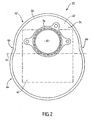
Fig. 2 is a rear view of a urostomy pouch; -
Fig. 3 is a cross section through the pouch showing how urine enters the pouch; -
Fig. 4 is a cross-section similar toFig. 3 showing how urine is collected; -
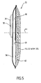
Fig. 5 is a cross section similar toFig. 4 showing the pouch when almost full. - Referring to
Figs. 2 to 5 of the drawings, aurostomy pouch 20 consists generally of afront wall 22 and arear wall 24 welded together around their commonperipheral seam 26 to define a pouch envelope. Thewalls front comfort layer 28 and arear comfort layer 30 of soft material are positioned outside thefront wall 22 andrear wall 24, and sealed thereto along the common seam 26 (to avoid cluttering the drawings the comfort layers are shown only inFigure 3 ). - An
entrance aperture 32 is provided in the upper region of therear wall 24, and acoupling member 34 is welded to the pouch in register with theaperture 32. In the present embodiment, thecoupling member 34 is intended to form a mechanical interlock with a complementary coupling member (not shown) worn on the body. However, in other embodiments, the coupling member may comprise an adhesive wafer for adhesive attachment directly to the body or to a body-side coupling member. - The interior of the
pouch 20 is divided by apartition 36 into anentrance chamber 38 which communicates with theentrance aperture 32 and acollection chamber 40. Apad 42 of or containing superabsorbent material is received in thecollection chamber 40, and extends above the lowermost level or point (indicated at 44) of theentrance aperture 32; as illustrated, thepad 42 is of approximately the same height as the interior of the pouch. - A currently preferred composition for the
pad 42 is that described inGB-A-2301350 superabsorbent 100 pbw. water 0.6 to 6 pbw. glycerol 5 to 30 pbw. - The glycerol provides significant advantages by acting as a humectant to increase the wicking effect and to avoid gel-locking when the urine contacts the superabsorbent. It also enables the composition to be formed into a self-supporting laminate pad by simply compressing the material between the upper and lower sheets, for example, paper sheets to amalgamate it structurally. The sheets may for example be of tissue paper. One of the sheets might be of plastics weldable paper, to enable the laminate to be secured in position in the pouch during manufacture by welding.
- As described in
GB 2301350 - In the present embodiment, the
partition 36 comprises a firstintermediate wall 46 of liquid impermeable plastics film, and a secondintermediate wall 48 of liquid permeable material. The first and second intermediate walls are positioned one behind the other, and are joined to the front and rear walls of the pouch at thecommon weld seam 26. The firstintermediate wall 46 extends only part-way down the length of the pouch, and serves, in use of the pouch, to direct incoming urine downwardly in the pouch, rather than allowing urine to pass directly to thesuperabsorbent containing pad 42. The secondintermediate wall 48 extends substantially the full length of the pouch. The intermediate walls together prevent thesuperabsorbent pad 42 from contacting directly the wearer's sensitive stoma. This can provide a degree of security and protection in case the superabsorbent material might irritate the wearer's stoma if in prolonged contact. - It will be appreciated that the intermediate walls thus define a
partition 36 with an upper liquidimpermeable protection region 50, and a lower liquidpermeable region 52. The use of twointermediate walls walls - In use, urine entering the pouch follows the path indicated by
arrow 60 inFig. 2 . The urine does not pass through the impermeable firstintermediate wall 46, but instead runs down towards the bottom of the pouch in theentrance chamber 38. Once the urine has passed below the firstintermediate wall 46, it is able to pass through the secondintermediate wall 48 into thecollection chamber 40 where it is soaked up by the superabsorbent pad 42 (Fig. 3 ). The nature of the superabsorbent material is such that, provided that thepad 42 is in contact with thepartition 36, the superabsorbent tends to draw any urine in theentrance chamber 38 through thepermeable wall 48 into thepad 42. The urine tends to wick up thepad 42 as it is absorbed, and the superabsorbent material interacts with the urine to form a gel. The superabsorbent material expands as it forms the gel. - By directing the urine downwardly in the
entrance chamber 38 before it passes into the collection chamber, there is less chance of excess urine splashing back against the stoma before all the urine is able to pass through thepartition 36. Also, the urine gels in thepad 42 from the bottom upwardly, thereby preventing unwanted initial bulging of thepad 42 in the region of theentrance aperture 32. It will be appreciated that such bulging of thepad 42 immediately opposite the entrance aperture might tend to obstruct the aperture. - The pores in the liquid permeable second
intermediate wall 48 are such that, although liquid may pass therethrough, the gellified urine is unable to pass back; the gellified urine thus remains trapped in thecollection chamber 40. In the present embodiment, the secondintermediate wall 48 is made of material having directional pores which permit liquid to flow therethrough in one direction, but obstruct the flow of liquid in the return direction. This is preferred because the superabsorbent laminate material can take a few seconds to absorb the urine, particularly if the urine is discharged into the pouch in relatively large quantities. - The result is that, even if the pouch is subjected to shaking by the wearer's physical movements, or is turned on its side if the wearer sits or reclines, the gellified urine will not tend to leak back into the
entrance chamber 38 and escape through theentrance aperture 32. Thepouch 20 can therefore provide optimum protection for the wearer. - As more urine is collected and absorbed by the pad 42 (
Figs 3 and 4 ), the urine will wick upwardly towards the top of the pad. Since thepad 42 extends above the lowermost point (44) of theaperture 32, this embodiment enables the full height of the pouch to be used for liquid collection. In other words, the region above thelevel 44 which is unused and wasted volume in previous designs of urostomy pouches, is able to be used as available volume for liquid collection. - In the present embodiment, the amount of superabsorbent in the
collection chamber 40 is greater than the amount of superabsorbent required to completely fill the volume of the collection chamber with gel. Therefore, even when the pouch becomes full, the material in thecollection chamber 40 remains as gel completely filling the chamber. - It will be appreciated that, for the sake of clarity, the drawings show the pouch walls separated from each other (almost inflated) so that the pouch structure is clear. However, during use of the pouch, the pouch will initially be maintained in a flat configuration. As urine is collected in the collection chamber (40), this chamber will tend to occupy the majority of the volume of the pouch. The
entrance chamber 38 will tend to remain generally flat. Therefore, the provision of theentrance chamber 38 does not reduce the effective capacity of themain collection chamber 40. - As best seen in
Fig. 2 , the pouch is has a figure-of-eight shape, defined by an upperarcuate profile region 62, and a lowerarcuate profile region 64 meeting at aslight waist 66. In use, thewaist 66 serves to control the extent to which the pouch can bulge, and helps maintain a relatively low (flat) pouch profile, even when thecollection chamber 40 is completely filled by gel. The waist therefore assists in holding thepad 42 flat against thepartition 36 so that urine will be drawn from theentrance chamber 38 into thecollection chamber 40 efficiently. - The upper and lower arcuate profile regions are generally arcs of a circle, and the
lower region 64 has a slightly greater lateral dimension (diameter) than theupper region 62. Theentrance aperture 32 is positioned generally in register with the centre of curvature of theupper region 62. - It has not been found necessary to fit a separate non-return valve in the present embodiment, because the one-way characteristic of the second
intermediate wall 48 and the gellification of the urine in thecollection chamber 40 is sufficient to prevent urine from splashing or leaking back through theentrance aperture 32. However, if desired, a one-way valve could be incorporated in theentrance chamber 38 just below theentrance aperture 32. It will be appreciated that the fitting of such a valve would not reduce the capacity of the pouch (a problem suffered in the prior art), because the full pouch height is still available for liquid collection in thecollection chamber 40. If desired, thewaist 66 could be extended downwardly (i.e. narrowed) to form a non-return type constriction below theentrance aperture 32. - The present embodiment is intended as a disposable, short duration urostomy pouch. The pouch is a little smaller than usual, having an overall height of about 16 cm, and an overall width of about 13 cm. Such a small size of pouch is able to be worn under sports clothing, without being embarrassingly prominent. The small size is made practicable by virtue of at least a portion of the upper region of the pouch being available as a liquid collection volume. Also, since the superabsorbent laminate material acts to gellify the urine, there is no sloshing of the urine inside the pouch; this makes the pouch suitable for use as an activity or sports pouch, enabling the ostomate more easily to engage in activities with much less risk of personal embarrassment.
- Although the above embodiment refers to a small urostomy pouch, the same principles may be used to improve the characteristics of larger pouches.
- The invention also provides greater freedom in the design and positioning of the urostomy pouch, in view of the wicking effect to absorb the urine. The pouch is able to collect urine in a region above the level of the inlet to the pouch. Such an effect has not been possible in any prior art designs.
- It will be appreciated that the foregoing description is merely illustrative of preferred forms of the invention, and that many modifications may be made using the above described principles. In particular, although the
partition 36 provides many advantages, this is not essential in all embodiments of the invention. - Also, although the illustrated embodiments have only two chambers, it will be appreciated that a greater number of chambers may be used if desired. For example, the inlet aperture could then communicate indirectly with the
intermediate chamber 38 via one or more additional, upstream, chambers. - The Applicant claims protection any novel feature or idea described herein and/or illustrated in the drawings whether or not emphasis has been placed thereon.
Claims (18)
- A urostomy pouch comprising:first and second walls (22,24) defining a pouch envelope;a third wall (36) for defining first and second chambers (38,40) within the envelope and arranged with a portion of one chamber (38) generally horizontally in front of the other (40) when the pouch is in an upright orientation in which it is worn;an entrance aperture (32) communicating directly with the first chamber (38); anda material (42) in the second chamber (40) for gelling liquid contents therein, for storing liquid in the second chamber (40) as a gel; characterised in that: the gelling material (42) extends above the lower level (44) of the entrance aperture (32) when the pouch is in said upright orientation in which it is worn normally, whereby the gelling material (42) is able to store liquid as a gel in an upper region of the second chamber (40) above said lower level (44) of the entrance aperture (32) and wherein
the gelling material (42) is screened from the entrance aperture by a wall or wall-portion (46) of liquid impermeable material, and
liquid entering the first chamber (38) from the entrance aperture (32) is guided downwardly and is admitted to the second chamber (40) only at a level lower than the level of the entrance aperture (32). - A pouch according to claim 1, wherein the pouch is ventless.
- A pouch according to any preceding claim, wherein the third wall (36) is configured to admit liquid from the first chamber (38) to the second chamber (40), but to obstruct the escape of gel from the second chamber (40).
- A pouch according to any preceding claim, wherein the third wall (36) comprises at least a portion (48) thereof having directional flow characteristics to admit liquid to flow from the first chamber (38) to the second chamber (40), but to obstruct the flow of liquid from the second chamber (40) to the first chamber (38).
- A pouch according to claim 3 or 4, wherein the third wall (36) comprises at least a portion (48) thereof of a material porous to liquid.
- A pouch according to any preceding claim, wherein the gelling material (42) has a wicking characteristic able to draw liquid upwardly by a wicking effect.
- A pouch according to any preceding claim, wherein the gelling material (42) comprises a superabsorbent material.
- A pouch according to claim 7, wherein the superabsorbent material comprises an alkali metal polyacrylate.
- A pouch according to claim 8, wherein the superabsorbent material comprises sodium polyacrylate.
- A pouch according to claim 7, 8 or 9 wherein the superabsorbent material forms part of a composition including glycerol.
- A pouch according to any preceding claim, wherein the third wall (36) comprises a liquid impermeable portion (46) and a liquid permeable portion (48).
- A pouch according to claim 11, wherein the third wall (36) comprises first and second layers, the first layer (46) being of liquid impermeable material, and the second layer (48) being of liquid permeable material.
- A pouch according to any preceding claim, wherein the pouch has an outer profile or a weld seam (26) consisting substantially of a first upper arcuate portion (62) and a second lower arcuate portion (64), at least one of the arcuate portions having a maximum transverse dimension greater than the transverse dimension at the point (66) where the first and second portions meet.
- A pouch according to claim 13, wherein the profile or seam (26) defines a figure-of-eight shape.
- A pouch according to claim 13 or 14, wherein one of the portions (64) has a greater maximum dimension than the other (62).
- A pouch according to claim 13, 14 or 15, wherein the profile or seam (26) includes a waist (66) at the point where the first and second portions (62,64) meet.
- A pouch according to any of claims 13 to 16, wherein at least one of the first and second portions (62,64) corresponds to an arc of a circle.
- A pouch according to any of claims 13 to 17, wherein the entrance aperture (32) is positioned generally in register with a centre of curvature of one of the portions (62).
Priority Applications (3)
| Application Number | Priority Date | Filing Date | Title |
|---|---|---|---|
| DK01125056.0T DK1177781T3 (en) | 1999-07-13 | 2000-07-05 | Bag for collecting material secreted by the body |
| ES01125056T ES2391944T3 (en) | 1999-07-13 | 2000-07-05 | Bag to collect material excreted by the body |
| EP01125056A EP1177781B1 (en) | 1999-07-13 | 2000-07-05 | Pouch for collecting matter excreted by the body |
Applications Claiming Priority (4)
| Application Number | Priority Date | Filing Date | Title |
|---|---|---|---|
| GB9916342 | 1999-07-13 | ||
| GBGB9916342.0A GB9916342D0 (en) | 1999-07-13 | 1999-07-13 | Pouch for collecting matter excreted by the body |
| GB9917019A GB2351909B (en) | 1999-07-13 | 1999-07-20 | Pouch for collecting matter excreted by the body |
| GB9917019 | 1999-07-20 |
Related Child Applications (2)
| Application Number | Title | Priority Date | Filing Date |
|---|---|---|---|
| EP01125056A Division EP1177781B1 (en) | 1999-07-13 | 2000-07-05 | Pouch for collecting matter excreted by the body |
| EP01125056.0 Division-Into | 2001-10-22 |
Publications (3)
| Publication Number | Publication Date |
|---|---|
| EP1068848A1 EP1068848A1 (en) | 2001-01-17 |
| EP1068848B1 EP1068848B1 (en) | 2004-10-13 |
| EP1068848B2 true EP1068848B2 (en) | 2010-08-25 |
Family
ID=26315760
Family Applications (2)
| Application Number | Title | Priority Date | Filing Date |
|---|---|---|---|
| EP01125056A Expired - Lifetime EP1177781B1 (en) | 1999-07-13 | 2000-07-05 | Pouch for collecting matter excreted by the body |
| EP00114415A Expired - Lifetime EP1068848B2 (en) | 1999-07-13 | 2000-07-05 | Pouch for collecting matter excreted by the body |
Family Applications Before (1)
| Application Number | Title | Priority Date | Filing Date |
|---|---|---|---|
| EP01125056A Expired - Lifetime EP1177781B1 (en) | 1999-07-13 | 2000-07-05 | Pouch for collecting matter excreted by the body |
Country Status (10)
| Country | Link |
|---|---|
| US (1) | US6685684B1 (en) |
| EP (2) | EP1177781B1 (en) |
| JP (1) | JP2001061878A (en) |
| AT (1) | ATE279167T1 (en) |
| AU (1) | AU770472B2 (en) |
| CA (1) | CA2313752C (en) |
| DE (1) | DE60014785T3 (en) |
| DK (2) | DK1177781T3 (en) |
| ES (2) | ES2229998T5 (en) |
| MX (1) | MXPA00006848A (en) |
Families Citing this family (45)
| Publication number | Priority date | Publication date | Assignee | Title |
|---|---|---|---|---|
| DE20207356U1 (en) * | 2002-05-08 | 2003-06-12 | Riesinger Birgit | Absorbent body for connection to skin and mucous membrane surfaces |
| GB0224986D0 (en) | 2002-10-28 | 2002-12-04 | Smith & Nephew | Apparatus |
| US6998871B2 (en) * | 2002-11-29 | 2006-02-14 | Sigmatel, Inc. | Configurable integrated circuit for use in a multi-function handheld device |
| GB0325129D0 (en) | 2003-10-28 | 2003-12-03 | Smith & Nephew | Apparatus in situ |
| US20050218154A1 (en) * | 2004-03-24 | 2005-10-06 | Selsby Adam B | Low Profile Fluid Container |
| US20060111682A1 (en) | 2004-06-24 | 2006-05-25 | Schena Kenneth R | Colostomy bag cleaning system |
| SE527759C2 (en) | 2004-10-12 | 2006-05-30 | Bengt-Inge Broden | Urine collection device, superabsorbent laminate board included in the device and method of manufacturing the disc |
| DE202004017052U1 (en) * | 2004-11-02 | 2005-06-09 | Riesinger, Birgit | Device for wound treatment using negative pressure |
| DE202004018245U1 (en) | 2004-11-24 | 2005-07-07 | Riesinger, Birgit | Drainage device for treating wounds using reduced pressure has absorption body with layer(s) of textile section enriched with super-absorbents enclosed by liquid transmissive sleeve; absorbed wound secretions remain in absorption body |
| JP2006255178A (en) * | 2005-03-17 | 2006-09-28 | Japan Absorbent Technology Institute | Male body fluid disposal article |
| US20080058736A1 (en) * | 2006-08-30 | 2008-03-06 | Reshamwala Piyush J | Sharps container having absorbent pad and method of making the same |
| DE102006047041A1 (en) | 2006-10-02 | 2008-04-10 | Birgit Riesinger | Areal absorbent body |
| GB201011173D0 (en) | 2010-07-02 | 2010-08-18 | Smith & Nephew | Provision of wound filler |
| GB201020005D0 (en) | 2010-11-25 | 2011-01-12 | Smith & Nephew | Composition 1-1 |
| AU2011333538C1 (en) | 2010-11-25 | 2015-07-30 | Bluestar Silicones France Sas | Composition I-II and products and uses thereof |
| USD669260S1 (en) | 2010-12-20 | 2012-10-23 | Davidson Guy P | Concealable beverage container |
| EP2750722A4 (en) * | 2011-11-15 | 2014-12-24 | Univ Emory | Extended wear devices for liquid deodorizers and containers including such devices |
| US20150159066A1 (en) | 2011-11-25 | 2015-06-11 | Smith & Nephew Plc | Composition, apparatus, kit and method and uses thereof |
| WO2013121717A1 (en) * | 2012-02-17 | 2013-08-22 | テルモ株式会社 | Container for housing biological excretion fluid |
| USD754332S1 (en) * | 2012-08-13 | 2016-04-19 | Andreas Fahl Medizintechnik—Vertrieb GmbH | Plaster for tracheostoma |
| US20160120706A1 (en) | 2013-03-15 | 2016-05-05 | Smith & Nephew Plc | Wound dressing sealant and use thereof |
| US11090183B2 (en) | 2014-11-25 | 2021-08-17 | Purewick Corporation | Container for collecting liquid for transport |
| US10952889B2 (en) | 2016-06-02 | 2021-03-23 | Purewick Corporation | Using wicking material to collect liquid for transport |
| US11376152B2 (en) | 2014-03-19 | 2022-07-05 | Purewick Corporation | Apparatus and methods for receiving discharged urine |
| US11806266B2 (en) | 2014-03-19 | 2023-11-07 | Purewick Corporation | Apparatus and methods for receiving discharged urine |
| JP6727617B2 (en) * | 2014-12-18 | 2020-07-22 | ジーイー・ヘルスケア・ユーケイ・リミテッド | Device, method and system for collecting waste from a bioreactor |
| US11571324B2 (en) * | 2016-05-04 | 2023-02-07 | Hollister Incorporated | Ostomy pouch with tortuous path |
| USD928946S1 (en) | 2016-06-02 | 2021-08-24 | Purewick Corporation | Urine receiving apparatus |
| US10973678B2 (en) | 2016-07-27 | 2021-04-13 | Purewick Corporation | Apparatus and methods for receiving discharged urine |
| US11278457B2 (en) | 2017-02-09 | 2022-03-22 | Hill-Rom Services, Inc. | Incontinence detection optimization using directional wicking |
| GB201715394D0 (en) * | 2017-09-22 | 2017-11-08 | Salts Healthcare Ltd | An ostomy appliance |
| CA3083537A1 (en) | 2017-12-15 | 2019-06-20 | Chiara Carolyn GLASROE | Improvements to incontinence assistance appliances and garments |
| CA3098570C (en) | 2018-05-01 | 2023-09-26 | Purewick Corporation | Fluid collection devices, related systems, and related methods |
| CA3098680A1 (en) | 2018-05-01 | 2019-11-07 | Purewick Corporation | Fluid collection garments |
| CN112770701A (en) | 2018-05-01 | 2021-05-07 | 普利维克公司 | Fluid collection devices, systems, and methods |
| USD929578S1 (en) | 2019-06-06 | 2021-08-31 | Purewick Corporation | Urine collection assembly |
| CN114502114A (en) | 2019-10-04 | 2022-05-13 | 康沃特克有限公司 | Ostomy appliance |
| HUE062484T2 (en) | 2019-10-04 | 2023-11-28 | Convatec Ltd | Ostomy appliance |
| GB202008258D0 (en) | 2020-06-02 | 2020-07-15 | Convatec Ltd | An ostomy pounch |
| USD967409S1 (en) | 2020-07-15 | 2022-10-18 | Purewick Corporation | Urine collection apparatus cover |
| US11801186B2 (en) | 2020-09-10 | 2023-10-31 | Purewick Corporation | Urine storage container handle and lid accessories |
| JP2023515438A (en) | 2021-01-19 | 2023-04-13 | ピュアウィック コーポレイション | Variable fluid collection device, system and method |
| JP2023553620A (en) | 2021-02-26 | 2023-12-25 | ピュアウィック コーポレイション | Fluid collection device having a drainage basin between a pipe opening and a barrier, and related systems and methods |
| US11938054B2 (en) | 2021-03-10 | 2024-03-26 | Purewick Corporation | Bodily waste and fluid collection with sacral pad |
| FR3127391B1 (en) * | 2021-09-28 | 2023-11-17 | Swiss Safe Collect Sa | Liquid collection device |
Citations (3)
| Publication number | Priority date | Publication date | Assignee | Title |
|---|---|---|---|---|
| US3613123A (en) † | 1968-12-31 | 1971-10-19 | Peanna Laangstroem & Co | Collecting receptacle for liquids,especially urine |
| DE3639171A1 (en) † | 1986-11-15 | 1988-05-26 | Sandler Helmut Helsa Werke | Colostomy bag |
| US5549587A (en) † | 1995-06-07 | 1996-08-27 | Norton; Walter L. | Ostomy bag |
Family Cites Families (17)
| Publication number | Priority date | Publication date | Assignee | Title |
|---|---|---|---|---|
| US4643726A (en) * | 1983-07-18 | 1987-02-17 | E. R. Squibb & Sons, Inc. | Incontinence insert |
| GB2145334B (en) | 1983-08-22 | 1986-08-13 | Craig Med Prod Ltd | Urostomy appliance |
| US4886509A (en) * | 1985-12-20 | 1989-12-12 | Lars Mattsson | Device for collecting and absorbing urine |
| US5531724A (en) * | 1987-01-14 | 1996-07-02 | American Innotek, Inc. | Fluid containment bag |
| GB2268882B (en) | 1992-07-22 | 1996-08-14 | Squibb & Sons Inc | Urostomy pouch & system |
| GB9416876D0 (en) * | 1994-08-19 | 1994-10-12 | Mcneil Ppc Inc | Male incontinence device |
| GB2301350B (en) * | 1995-06-22 | 1997-09-17 | Bristol Myers Squibb Co | Method & formulation for absorbing & treating waste |
| US5976118A (en) * | 1996-06-26 | 1999-11-02 | Bristol-Myers Squibb Company | Water--closet disposable pouch |
| US5695485A (en) * | 1996-07-26 | 1997-12-09 | Duperret; Ruth M. | Male continence pouch and shield |
| US6186990B1 (en) * | 1997-02-05 | 2001-02-13 | Reachgood Industrial Company | To a human bodily fluid collection device and method of collecting and absorbing the same |
| US6530909B1 (en) * | 1997-02-27 | 2003-03-11 | Uni-Charm Corporation | Urine absorbent bag |
| EP0870513A1 (en) * | 1997-04-04 | 1998-10-14 | Keiji Komine | Liquid absorbent material used in a pouch for a stoma |
| GB2325432B (en) * | 1997-05-21 | 1999-12-22 | Bristol Myers Squibb Co | Absorbing aqueous matter |
| GB2329339B (en) * | 1997-09-18 | 2000-03-29 | Bristol Myers Squibb Co | Absorbent member for ostomy use |
| GB2351238B (en) * | 1998-08-13 | 2001-10-24 | Bristol Myers Squibb Co | Adhesive wafer for ostomy pouch |
| JP3877451B2 (en) * | 1998-10-30 | 2007-02-07 | ユニ・チャーム株式会社 | Urine pad |
| JP3815932B2 (en) * | 1999-09-21 | 2006-08-30 | ユニ・チャーム株式会社 | Disposable urine collection bags for men |
-
2000
- 2000-07-05 AT AT00114415T patent/ATE279167T1/en not_active IP Right Cessation
- 2000-07-05 EP EP01125056A patent/EP1177781B1/en not_active Expired - Lifetime
- 2000-07-05 ES ES00114415T patent/ES2229998T5/en not_active Expired - Lifetime
- 2000-07-05 DE DE60014785T patent/DE60014785T3/en not_active Expired - Lifetime
- 2000-07-05 EP EP00114415A patent/EP1068848B2/en not_active Expired - Lifetime
- 2000-07-05 DK DK01125056.0T patent/DK1177781T3/en active
- 2000-07-05 ES ES01125056T patent/ES2391944T3/en not_active Expired - Lifetime
- 2000-07-05 DK DK00114415.3T patent/DK1068848T4/en active
- 2000-07-10 US US09/613,259 patent/US6685684B1/en not_active Expired - Fee Related
- 2000-07-12 AU AU47179/00A patent/AU770472B2/en not_active Ceased
- 2000-07-12 CA CA002313752A patent/CA2313752C/en not_active Expired - Fee Related
- 2000-07-12 MX MXPA00006848A patent/MXPA00006848A/en active IP Right Grant
- 2000-07-13 JP JP2000212840A patent/JP2001061878A/en active Pending
Patent Citations (3)
| Publication number | Priority date | Publication date | Assignee | Title |
|---|---|---|---|---|
| US3613123A (en) † | 1968-12-31 | 1971-10-19 | Peanna Laangstroem & Co | Collecting receptacle for liquids,especially urine |
| DE3639171A1 (en) † | 1986-11-15 | 1988-05-26 | Sandler Helmut Helsa Werke | Colostomy bag |
| US5549587A (en) † | 1995-06-07 | 1996-08-27 | Norton; Walter L. | Ostomy bag |
Also Published As
| Publication number | Publication date |
|---|---|
| DK1068848T3 (en) | 2005-02-14 |
| JP2001061878A (en) | 2001-03-13 |
| EP1177781A3 (en) | 2004-04-07 |
| EP1068848A1 (en) | 2001-01-17 |
| ES2391944T3 (en) | 2012-12-03 |
| DE60014785D1 (en) | 2004-11-18 |
| US6685684B1 (en) | 2004-02-03 |
| DK1177781T3 (en) | 2012-11-05 |
| ES2229998T5 (en) | 2011-01-27 |
| AU770472B2 (en) | 2004-02-19 |
| EP1177781B1 (en) | 2012-08-22 |
| MXPA00006848A (en) | 2002-06-04 |
| DE60014785T2 (en) | 2006-02-16 |
| AU4717900A (en) | 2001-01-18 |
| ATE279167T1 (en) | 2004-10-15 |
| EP1177781A2 (en) | 2002-02-06 |
| DE60014785T3 (en) | 2011-03-17 |
| ES2229998T3 (en) | 2005-05-01 |
| CA2313752A1 (en) | 2001-01-13 |
| DK1068848T4 (en) | 2010-11-29 |
| EP1068848B1 (en) | 2004-10-13 |
| CA2313752C (en) | 2008-09-23 |
Similar Documents
| Publication | Publication Date | Title |
|---|---|---|
| EP1068848B2 (en) | Pouch for collecting matter excreted by the body | |
| ES2362627T3 (en) | DEODORANT FILTER FOR AN OSTOMY DEVICE. | |
| US9549839B2 (en) | Ostomy bag with a filter construction | |
| US4490145A (en) | Ostomy pouch with deodorizing filter | |
| US4917692A (en) | Faecal incontinence bag | |
| US5348546A (en) | Ostomy bag with liquid-gas separation device | |
| US4372308A (en) | Ostomy bag including filter means | |
| US5549587A (en) | Ostomy bag | |
| EP2575705B1 (en) | Filter with an extension element | |
| AU2002339394A1 (en) | An ostomy appliance | |
| GB2139501A (en) | Ostomy bag, particularly for ileostomy patients | |
| JP2000126216A (en) | Filter built into artificial fistula bag and gas ventilation system | |
| US9101483B2 (en) | Ostomy bag with intermediate filter element | |
| GB2351909A (en) | Pouch for collecting matter excreted by the body | |
| GB2247172A (en) | Ileostomy bag filter protection arrangement | |
| GB2080116A (en) | Drainage bag |
Legal Events
| Date | Code | Title | Description |
|---|---|---|---|
| PUAI | Public reference made under article 153(3) epc to a published international application that has entered the european phase |
Free format text: ORIGINAL CODE: 0009012 |
|
| AK | Designated contracting states |
Kind code of ref document: A1 Designated state(s): AT BE CH CY DE DK ES FI FR GB GR IE IT LI LU MC NL PT SE |
|
| AX | Request for extension of the european patent |
Free format text: AL;LT;LV;MK;RO;SI |
|
| 17P | Request for examination filed |
Effective date: 20010712 |
|
| AKX | Designation fees paid |
Free format text: AT BE CH CY DE DK ES FI FR GB GR IE IT LI LU MC NL PT SE |
|
| 17Q | First examination report despatched |
Effective date: 20021018 |
|
| GRAP | Despatch of communication of intention to grant a patent |
Free format text: ORIGINAL CODE: EPIDOSNIGR1 |
|
| GRAS | Grant fee paid |
Free format text: ORIGINAL CODE: EPIDOSNIGR3 |
|
| GRAA | (expected) grant |
Free format text: ORIGINAL CODE: 0009210 |
|
| AK | Designated contracting states |
Kind code of ref document: B1 Designated state(s): AT BE CH CY DE DK ES FI FR GB GR IE IT LI LU MC NL PT SE |
|
| PG25 | Lapsed in a contracting state [announced via postgrant information from national office to epo] |
Ref country code: AT Free format text: LAPSE BECAUSE OF FAILURE TO SUBMIT A TRANSLATION OF THE DESCRIPTION OR TO PAY THE FEE WITHIN THE PRESCRIBED TIME-LIMIT Effective date: 20041013 Ref country code: BE Free format text: LAPSE BECAUSE OF FAILURE TO SUBMIT A TRANSLATION OF THE DESCRIPTION OR TO PAY THE FEE WITHIN THE PRESCRIBED TIME-LIMIT Effective date: 20041013 Ref country code: FI Free format text: LAPSE BECAUSE OF FAILURE TO SUBMIT A TRANSLATION OF THE DESCRIPTION OR TO PAY THE FEE WITHIN THE PRESCRIBED TIME-LIMIT Effective date: 20041013 Ref country code: CH Free format text: LAPSE BECAUSE OF FAILURE TO SUBMIT A TRANSLATION OF THE DESCRIPTION OR TO PAY THE FEE WITHIN THE PRESCRIBED TIME-LIMIT Effective date: 20041013 Ref country code: LI Free format text: LAPSE BECAUSE OF FAILURE TO SUBMIT A TRANSLATION OF THE DESCRIPTION OR TO PAY THE FEE WITHIN THE PRESCRIBED TIME-LIMIT Effective date: 20041013 |
|
| REG | Reference to a national code |
Ref country code: GB Ref legal event code: FG4D |
|
| REG | Reference to a national code |
Ref country code: CH Ref legal event code: EP |
|
| REG | Reference to a national code |
Ref country code: IE Ref legal event code: FG4D |
|
| REF | Corresponds to: |
Ref document number: 60014785 Country of ref document: DE Date of ref document: 20041118 Kind code of ref document: P |
|
| PG25 | Lapsed in a contracting state [announced via postgrant information from national office to epo] |
Ref country code: GR Free format text: LAPSE BECAUSE OF FAILURE TO SUBMIT A TRANSLATION OF THE DESCRIPTION OR TO PAY THE FEE WITHIN THE PRESCRIBED TIME-LIMIT Effective date: 20050113 |
|
| REG | Reference to a national code |
Ref country code: SE Ref legal event code: TRGR |
|
| REG | Reference to a national code |
Ref country code: DK Ref legal event code: T3 |
|
| REG | Reference to a national code |
Ref country code: CH Ref legal event code: PL |
|
| REG | Reference to a national code |
Ref country code: ES Ref legal event code: FG2A Ref document number: 2229998 Country of ref document: ES Kind code of ref document: T3 |
|
| PG25 | Lapsed in a contracting state [announced via postgrant information from national office to epo] |
Ref country code: CY Free format text: LAPSE BECAUSE OF FAILURE TO SUBMIT A TRANSLATION OF THE DESCRIPTION OR TO PAY THE FEE WITHIN THE PRESCRIBED TIME-LIMIT Effective date: 20050705 |
|
| PLBI | Opposition filed |
Free format text: ORIGINAL CODE: 0009260 |
|
| PLBI | Opposition filed |
Free format text: ORIGINAL CODE: 0009260 |
|
| PLAX | Notice of opposition and request to file observation + time limit sent |
Free format text: ORIGINAL CODE: EPIDOSNOBS2 |
|
| 26 | Opposition filed |
Opponent name: HOLLISTER INCORPORATED Effective date: 20050711 |
|
| 26 | Opposition filed |
Opponent name: HOLLISTER INCORPORATED Effective date: 20050711 Opponent name: STUKENKEMPER, JOCHEN Effective date: 20050712 |
|
| ET | Fr: translation filed | ||
| NLR1 | Nl: opposition has been filed with the epo |
Opponent name: STUKENKEMPER, JOCHEN Opponent name: HOLLISTER INCORPORATED |
|
| PLAF | Information modified related to communication of a notice of opposition and request to file observations + time limit |
Free format text: ORIGINAL CODE: EPIDOSCOBS2 |
|
| PLBB | Reply of patent proprietor to notice(s) of opposition received |
Free format text: ORIGINAL CODE: EPIDOSNOBS3 |
|
| PLAB | Opposition data, opponent's data or that of the opponent's representative modified |
Free format text: ORIGINAL CODE: 0009299OPPO |
|
| R26 | Opposition filed (corrected) |
Opponent name: HOLLISTER INCORPORATED Effective date: 20050711 Opponent name: STUKENKEMPER, JOCHEN Effective date: 20050712 |
|
| PG25 | Lapsed in a contracting state [announced via postgrant information from national office to epo] |
Ref country code: PT Free format text: LAPSE BECAUSE OF NON-PAYMENT OF DUE FEES Effective date: 20050313 |
|
| NLR1 | Nl: opposition has been filed with the epo |
Opponent name: HOLLISTER INCORPORATED Opponent name: STUKENKEMPER, JOCHEN |
|
| REG | Reference to a national code |
Ref country code: GB Ref legal event code: 732E |
|
| APAH | Appeal reference modified |
Free format text: ORIGINAL CODE: EPIDOSCREFNO |
|
| APBM | Appeal reference recorded |
Free format text: ORIGINAL CODE: EPIDOSNREFNO |
|
| APBP | Date of receipt of notice of appeal recorded |
Free format text: ORIGINAL CODE: EPIDOSNNOA2O |
|
| APBU | Appeal procedure closed |
Free format text: ORIGINAL CODE: EPIDOSNNOA9O |
|
| REG | Reference to a national code |
Ref country code: NL Ref legal event code: SD Effective date: 20100303 |
|
| PUAH | Patent maintained in amended form |
Free format text: ORIGINAL CODE: 0009272 |
|
| STAA | Information on the status of an ep patent application or granted ep patent |
Free format text: STATUS: PATENT MAINTAINED AS AMENDED |
|
| PGFP | Annual fee paid to national office [announced via postgrant information from national office to epo] |
Ref country code: MC Payment date: 20100628 Year of fee payment: 11 |
|
| 27A | Patent maintained in amended form |
Effective date: 20100825 |
|
| AK | Designated contracting states |
Kind code of ref document: B2 Designated state(s): AT BE CH CY DE DK ES FI FR GB GR IE IT LI LU MC NL PT SE |
|
| REG | Reference to a national code |
Ref country code: FR Ref legal event code: TP |
|
| PGFP | Annual fee paid to national office [announced via postgrant information from national office to epo] |
Ref country code: IE Payment date: 20100712 Year of fee payment: 11 |
|
| REG | Reference to a national code |
Ref country code: NL Ref legal event code: T3 |
|
| REG | Reference to a national code |
Ref country code: DK Ref legal event code: T4 |
|
| PGFP | Annual fee paid to national office [announced via postgrant information from national office to epo] |
Ref country code: LU Payment date: 20100716 Year of fee payment: 11 |
|
| REG | Reference to a national code |
Ref country code: SE Ref legal event code: RPEO |
|
| REG | Reference to a national code |
Ref country code: ES Ref legal event code: DC2A Effective date: 20110117 |
|
| PGFP | Annual fee paid to national office [announced via postgrant information from national office to epo] |
Ref country code: DK Payment date: 20110712 Year of fee payment: 12 |
|
| PG25 | Lapsed in a contracting state [announced via postgrant information from national office to epo] |
Ref country code: MC Free format text: LAPSE BECAUSE OF NON-PAYMENT OF DUE FEES Effective date: 20110731 |
|
| REG | Reference to a national code |
Ref country code: IE Ref legal event code: MM4A |
|
| PG25 | Lapsed in a contracting state [announced via postgrant information from national office to epo] |
Ref country code: IE Free format text: LAPSE BECAUSE OF NON-PAYMENT OF DUE FEES Effective date: 20110705 |
|
| PGFP | Annual fee paid to national office [announced via postgrant information from national office to epo] |
Ref country code: GB Payment date: 20120704 Year of fee payment: 13 Ref country code: SE Payment date: 20120711 Year of fee payment: 13 |
|
| PGFP | Annual fee paid to national office [announced via postgrant information from national office to epo] |
Ref country code: DE Payment date: 20120627 Year of fee payment: 13 Ref country code: FR Payment date: 20120719 Year of fee payment: 13 Ref country code: IT Payment date: 20120714 Year of fee payment: 13 Ref country code: ES Payment date: 20120824 Year of fee payment: 13 |
|
| PGFP | Annual fee paid to national office [announced via postgrant information from national office to epo] |
Ref country code: NL Payment date: 20120710 Year of fee payment: 13 |
|
| PG25 | Lapsed in a contracting state [announced via postgrant information from national office to epo] |
Ref country code: LU Free format text: LAPSE BECAUSE OF NON-PAYMENT OF DUE FEES Effective date: 20110705 |
|
| REG | Reference to a national code |
Ref country code: NL Ref legal event code: V1 Effective date: 20140201 |
|
| REG | Reference to a national code |
Ref country code: DK Ref legal event code: EBP Effective date: 20130731 |
|
| REG | Reference to a national code |
Ref country code: SE Ref legal event code: EUG |
|
| GBPC | Gb: european patent ceased through non-payment of renewal fee |
Effective date: 20130705 |
|
| REG | Reference to a national code |
Ref country code: DE Ref legal event code: R119 Ref document number: 60014785 Country of ref document: DE Effective date: 20140201 |
|
| REG | Reference to a national code |
Ref country code: FR Ref legal event code: ST Effective date: 20140331 |
|
| PG25 | Lapsed in a contracting state [announced via postgrant information from national office to epo] |
Ref country code: DE Free format text: LAPSE BECAUSE OF NON-PAYMENT OF DUE FEES Effective date: 20140201 Ref country code: SE Free format text: LAPSE BECAUSE OF NON-PAYMENT OF DUE FEES Effective date: 20130706 Ref country code: GB Free format text: LAPSE BECAUSE OF NON-PAYMENT OF DUE FEES Effective date: 20130705 Ref country code: NL Free format text: LAPSE BECAUSE OF NON-PAYMENT OF DUE FEES Effective date: 20140201 |
|
| PG25 | Lapsed in a contracting state [announced via postgrant information from national office to epo] |
Ref country code: FR Free format text: LAPSE BECAUSE OF NON-PAYMENT OF DUE FEES Effective date: 20130731 Ref country code: IT Free format text: LAPSE BECAUSE OF NON-PAYMENT OF DUE FEES Effective date: 20130705 |
|
| PG25 | Lapsed in a contracting state [announced via postgrant information from national office to epo] |
Ref country code: DK Free format text: LAPSE BECAUSE OF NON-PAYMENT OF DUE FEES Effective date: 20130731 |
|
| REG | Reference to a national code |
Ref country code: ES Ref legal event code: FD2A Effective date: 20141014 |
|
| PG25 | Lapsed in a contracting state [announced via postgrant information from national office to epo] |
Ref country code: ES Free format text: LAPSE BECAUSE OF NON-PAYMENT OF DUE FEES Effective date: 20130706 |