EP1034092B2 - Electric system for a motor vehicle - Google Patents
Electric system for a motor vehicle Download PDFInfo
- Publication number
- EP1034092B2 EP1034092B2 EP98962266A EP98962266A EP1034092B2 EP 1034092 B2 EP1034092 B2 EP 1034092B2 EP 98962266 A EP98962266 A EP 98962266A EP 98962266 A EP98962266 A EP 98962266A EP 1034092 B2 EP1034092 B2 EP 1034092B2
- Authority
- EP
- European Patent Office
- Prior art keywords
- onboard electrical
- electrical subsystem
- generator
- starter
- subsystem
- Prior art date
- Legal status (The legal status is an assumption and is not a legal conclusion. Google has not performed a legal analysis and makes no representation as to the accuracy of the status listed.)
- Expired - Lifetime
Links
Images
Classifications
-
- H—ELECTRICITY
- H02—GENERATION; CONVERSION OR DISTRIBUTION OF ELECTRIC POWER
- H02J—CIRCUIT ARRANGEMENTS OR SYSTEMS FOR SUPPLYING OR DISTRIBUTING ELECTRIC POWER; SYSTEMS FOR STORING ELECTRIC ENERGY
- H02J1/00—Circuit arrangements for dc mains or dc distribution networks
- H02J1/08—Three-wire systems; Systems having more than three wires
-
- B—PERFORMING OPERATIONS; TRANSPORTING
- B60—VEHICLES IN GENERAL
- B60R—VEHICLES, VEHICLE FITTINGS, OR VEHICLE PARTS, NOT OTHERWISE PROVIDED FOR
- B60R16/00—Electric or fluid circuits specially adapted for vehicles and not otherwise provided for; Arrangement of elements of electric or fluid circuits specially adapted for vehicles and not otherwise provided for
- B60R16/02—Electric or fluid circuits specially adapted for vehicles and not otherwise provided for; Arrangement of elements of electric or fluid circuits specially adapted for vehicles and not otherwise provided for electric constitutive elements
- B60R16/03—Electric or fluid circuits specially adapted for vehicles and not otherwise provided for; Arrangement of elements of electric or fluid circuits specially adapted for vehicles and not otherwise provided for electric constitutive elements for supply of electrical power to vehicle subsystems or for
-
- H—ELECTRICITY
- H02—GENERATION; CONVERSION OR DISTRIBUTION OF ELECTRIC POWER
- H02J—CIRCUIT ARRANGEMENTS OR SYSTEMS FOR SUPPLYING OR DISTRIBUTING ELECTRIC POWER; SYSTEMS FOR STORING ELECTRIC ENERGY
- H02J1/00—Circuit arrangements for dc mains or dc distribution networks
- H02J1/08—Three-wire systems; Systems having more than three wires
- H02J1/082—Plural DC voltage, e.g. DC supply voltage with at least two different DC voltage levels
-
- H—ELECTRICITY
- H02—GENERATION; CONVERSION OR DISTRIBUTION OF ELECTRIC POWER
- H02J—CIRCUIT ARRANGEMENTS OR SYSTEMS FOR SUPPLYING OR DISTRIBUTING ELECTRIC POWER; SYSTEMS FOR STORING ELECTRIC ENERGY
- H02J2310/00—The network for supplying or distributing electric power characterised by its spatial reach or by the load
- H02J2310/40—The network being an on-board power network, i.e. within a vehicle
- H02J2310/46—The network being an on-board power network, i.e. within a vehicle for ICE-powered road vehicles
Definitions
- the invention relates to a vehicle electrical system for a motor vehicle according to claim 1.
- vehicle electrical systems are used in particular for connecting consumers to on-board energy storage, in particular a battery, and on-board power generator, in particular a starter generator coupled to the motor vehicle internal combustion engine; If high-current consumers are also connected to the vehicle electrical system, it is expedient for loss minimization to supply a second voltage, which is higher than a first battery-side voltage, to supply them.
- a vehicle electrical system which receives its power from a starter / generator, which is connected via pulse inverters and a 300 volt DC link and a bidirectional converter with a 24 volt ring network and a 24 volt battery, with other consumers higher voltage than 24 volts and a socket with 220 volt 50 Hz voltage from the Bornetzsystem be supplied.
- WO 97/08456 discloses a starter / generator for an internal combustion engine for a motor vehicle, comprising an inverter for generating the voltages required by the electric machine.
- the inverter is connected to a vehicle electrical system at a low voltage level (12 V) and converts this low voltage to a higher intermediate circuit level and vice versa.
- low voltage loads are connected and at the higher voltage level the starter / generator and other higher voltage loads are connected.
- a second vehicle electrical system voltage is to be made available with the least possible outlay in terms of hardware and software.
- the solution to this problem is achieved according to the invention by a built-up according to claim 1 electrical system; advantageous embodiments of the invention are the subject of the dependent claims.
- the electrical system according to the invention makes it possible to charge with the help of the switching or connecting device with only one boost converter on the one hand a starting capacitor for the starter-generator with a correspondingly high voltage or the second board power supply from the battery and on the other hand in the generator mode of Starter generator using the inverter associated with the starter-generator to supply the second on-board power supply by appropriate control of the inverter with a voltage that is increased relative to the battery voltage and compared to the voltage of the starter-generator is reduced.
- the starting capacitor is then used as a DC link capacitor in the generator mode.
- the electrical switching or connecting device consists in circuitry particularly low expenditure of a first connection from the first on-board power supply to the third on-board power supply with blocking in the opposite direction, further from a second connection from the first on-board power supply to the second on-board power supply with blocking in the opposite direction and switching only when powering the second on-board power supply from the first on-board power supply and from a third connection from the third on-board power supply to the second on-board power supply with switching only when feeding the second on-board power supply from the third on-board power supply provided;
- for blocking in the opposite direction diodes and for switching on or switching off the individual switchable connections depending on a Tyristor or transistor, in particular IGBT provided.
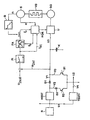
- the electrical system shown in the figure can basically be divided into a first onboard power supply U1 with a voltage level of e.g. 12 volts corresponding to the voltage of the battery B, into a second on-board power supply U2 for supplying high current consumers with a voltage level of e.g. 180 volts, into a third on-board power supply U3 with a voltage level of e.g.
- a control part is used for energy-optimal operation of the intended as a starter generator SG asynchronous machine, preferably with squirrel cage.
- an electrical switching or connecting device V1-V3 with a first connection V1 from the first on-board power supply U1 to the third on-board power supply U3 with blocking in the opposite direction and with a second connection V2 from the first on-board power supply U1 to the second on-board power supply U2 with switching on only when feeding the second on-board power supply unit U2 from the first on-board power supply unit U1 and with a third connection V3 from the third power supply unit
- the second on-board power supply unit U2 can be connected to the second vehicle electrical system voltage of, for example, by closing the switch S2 in the connection V2 by means of the step-up converter HSST. 180 volts brought and be supplied with energy from the battery B.
- the diode D1 remains in the locked state, since the starting capacitor K is usually at a relative to the voltage level of the second board power supply U2 increased voltage level.
- the internal combustion engine VB can be raised to a speed of approximately 400-700 rpm with the aid of the asynchronous motor of the starter generator SG; in the case of an electronic valve control, the valves are suitably fully opened during startup and thus provided without compression.
- the internal combustion engine VB can be ignited in normal valve position and the starter generator SG can be switched off on the drive side.
- the energy pre-stored in the starting capacitor K is insufficient, in the event that the voltage level of the third on-board power supply U3 is smaller than the voltage level of the second on-board power supply U2, additional energy from the battery B via the boost converter HSST and the connection V1 for the supplied via the inverter U starter generator SG are related.
- the starter generator SG can go into the generator mode.
- the voltage level of the third on-board power supply unit U3 as intermediate circuit voltage via the converter U and the starting capacitor K expediently used as intermediate circuit capacitor is reduced to the voltage level of the second onboard power supply unit U2, e.g. to 180 volts, regulated.
- the switch S2 is opened and thus the connection V2 is interrupted and the switch S1 is closed and thus the connection V3 is established by the on-board power supply unit U3 for the on-board power supply unit U2; the boost converter HSST is expediently put out of operation.
- the starter generator SG now operates in generator mode and supplies the regulated power supply U2 and the high-current consumers connected thereto via the regulated intermediate circuit voltage of the onboard power supply U3.
- a buck converter TSST DC-DC converter
- the electrical losses in both the inverter U and provided for the starter-generator SG asynchronous machine advantageously characterized low held that in a field-oriented control FOR the internal moment M i1 of the induction machine of the starter generator SG on the principle of loss-optimal control or regulation of the rotor flux by appropriate adaptation of the magnetizing current i ' u as a function of a corresponding to the respective required drive torque determined active current i sq is set.
- the field-oriented control of the asynchronous machine is based on the mathematical description of the dynamic machine behavior with room pointer sizes.
- Field orientation means that one connects the freely selectable reference axis of this mathematical machine model with respect to their angular position with the Rotorflußraum adapter, the Statorflußraum adapter or the Lucasspaltflußraum adapter.
- the mathematically simplest machine structure and thus also the simplest structure of a control result when the rotor flow space vector is selected as the orientation variable.
- the structure of the machine then resembles in the specification of the stator current space hand of a separately excited compensated DC machine.
- the field-oriented control of the asynchronous machine is achieved by predetermining the components of the stator current indicator of the machine, shown in the field-oriented coordinate system, as controlled variables. By means of a simple decoupling, the magnitude of the flux space vector and the internal torque are independently controllable.
- the intermediate circuit voltage according to the voltage level of the second board power supply U2 on the one hand and the desired value u 2 is to this intermediate circuit voltage is expected, and in a PI-formers of corresponding active current i sq defined.
- the corresponding magnetizing current i ⁇ ' is determined in accordance with the aforementioned formulas according to the principle of loss-optimal field-oriented regulation f S in a frequency adapter FA and via the field-oriented regulation FOR of the converter U or the asynchronous machine the starter-generator SG driven.
- the magnetizing current i ⁇ ' is additionally advantageously set as a function of a limiter B, such that the magnetizing current can be limited at a higher rotational speed, in particular to prevent thermal overload or in the sense of a field weakening operation.
Description
Die Erfindung bezieht sich auf ein Bordnetz für ein Kraftfahrzeug gemäß Patentanspruch 1. Derartige Bordnetze dienen insbesondere zum Anschluß von Verbrauchern an bordnetzseitige Energiespeicher, insbesondere eine Batterie, und bordnetzseitige Energieerzeuger, insbesondere einen mit der Kraftfahrzeug-Verbrennungsmaschine koppelbaren Starter-Generator; falls auch Hochstrom-Verbrauchern an das Bordnetz angeschlossen sind, ist es zur Verlustminimierung zweckmäßig, zu deren Versorgung eine zweite, gegenüber einer ersten batterieseitigen Spannung erhöhte Spannung vorzusehen.The invention relates to a vehicle electrical system for a motor vehicle according to
Durch die
In dem Dokument
Gemäß Aufgabe vorliegender Erfindung soll mit möglichst geringem Aufwand hinsichtlich Hardware und Software eine zweite Bordnetzspannung zur Verfügung gestellt werden. Die Lösung dieser Aufgabe gelingt erfindungsgemäß durch ein gemäß Patentanspruch 1 aufgebautes Bordnetz; vorteilhafte Ausgestaltungen der Erfindung sind jeweils Gegenstand der Unteransprüche.In accordance with the object of the present invention, a second vehicle electrical system voltage is to be made available with the least possible outlay in terms of hardware and software. The solution to this problem is achieved according to the invention by a built-up according to
Das erfindungsgemäße Bordnetz erlaubt es, mit Hilfe der Schalt- bzw. Verbindungsvorrichtung mit nur einem Hochsetzsteller sowohl einerseits einen Start-Kondensator für den Starter-Generator mit einer entsprechend hohen Spannung aufzuladen bzw. das zweite Bordnetzteil aus der Batterie zu versorgen und andererseits im Generatorbetrieb des Starter-Generators unter Verwendung des dem Starter-Generator zugeordneten Umrichters das zweite Bordnetzteil durch entsprechende Regelung des Umrichters mit einer Spannung zu versorgen, die gegenüber der Batteriespannung erhöht und gegenüber der Spannung des Starter-Generators herabgesetzt ist.The electrical system according to the invention makes it possible to charge with the help of the switching or connecting device with only one boost converter on the one hand a starting capacitor for the starter-generator with a correspondingly high voltage or the second board power supply from the battery and on the other hand in the generator mode of Starter generator using the inverter associated with the starter-generator to supply the second on-board power supply by appropriate control of the inverter with a voltage that is increased relative to the battery voltage and compared to the voltage of the starter-generator is reduced.
Zweckmäßigerweise wird im Generatorbetrieb der Start-Kondensator dann als Zwischenkreiskondensator eingesetzt.Conveniently, the starting capacitor is then used as a DC link capacitor in the generator mode.
Die elektrische Schalt- bzw. Verbindungsvorrichtung besteht in schaltungstechnisch besonders aufwandsarmer Weise aus einer ersten Verbindung von dem ersten Bordnetzteil zu dem dritten Bordnetzteil mit Sperrung in Gegenrichtung, weiterhin aus einer zweiten Verbindung von dem ersten Bordnetzteil zu dem zweiten Bordnetzteil mit Sperrung in Gegenrichtung und Einschaltung nur bei Speisung des zweiten Bordnetzteils aus dem ersten Bordnetzteil sowie aus einer dritten Verbindung von dem dritten Bordnetzteil zu dem zweiten Bordnetzteil mit Einschaltung nur bei Speisung des zweiten Bordnetzteils aus dem dritten Bordnetzteil vorgesehen; zweckmäßigerweise werden zur Sperrung in Gegenrichtung Dioden und zur Ein- bzw. Abschaltung der einzelnen schaltbaren Verbindungen je ein Tyristor bzw. Transistor, insbesondere IGBT, vorgesehen.The electrical switching or connecting device consists in circuitry particularly low expenditure of a first connection from the first on-board power supply to the third on-board power supply with blocking in the opposite direction, further from a second connection from the first on-board power supply to the second on-board power supply with blocking in the opposite direction and switching only when powering the second on-board power supply from the first on-board power supply and from a third connection from the third on-board power supply to the second on-board power supply with switching only when feeding the second on-board power supply from the third on-board power supply provided; Expediently, for blocking in the opposite direction diodes and for switching on or switching off the individual switchable connections depending on a Tyristor or transistor, in particular IGBT provided.
Mit geringem schaltungs- und steuerungstechnischen Zusatzaufwand kann im Generatorbetrieb des Starter-Generators auch eine Nachladung der Batterie bzw. eine Versorgung des ersten Bordnetzteils aus dem Starter-Generator dadurch erreicht werden, daß der erste Bordnetzteil über einen Tiefsetzer mit dem zweiten Bordnetzteil verbunden ist; in diesem Fall erfolgt also ein Leistungsfluß vom Starter-Generator über den Umrichter mit Zwischenkreiskondensator über die Verbindung zwischen dem dritten Bordnetzteil und dem zweiten Bordnetzteil und die anschließende Verbindung von dem zweiten Bordnetzteil über den Tiefsetzer zu dem ersten Bordnetzteil. Als Zwischenkreis-Kondensator wird dabei zweckmäßigerweise der zum Starten des Starter-Generators vorgesehene Start-Kondensator benutzt.With little additional circuitry and control overhead can also be in the generator mode of the starter generator recharging the battery or a supply of the first on-board power supply from the starter generator achieved in that the first on-board power supply is connected via a buck converter to the second board power supply; In this case, therefore, there is a power flow from the starter-generator via the inverter with intermediate circuit capacitor via the connection between the third on-board power supply and the second onboard power supply and the subsequent connection from the second on-board power supply via the buck converter to the first on-board power supply. As a DC link capacitor while suitably provided for starting the starter-generator start capacitor is used.
Die Erfindung sowie weitere vorteilhafte Ausgestaltungen der Erfindung werden im folgenden anhand eines in der Figur schematisch dargestellten Bordnetzes für ein Kraftfahrzeug mit einem batterieseitigen ersten Bordnetzteil, einem zweiten Bordnetzteils zur Versorgung von Verbrauchern, insbesondere Hochstrom-Verbrauchern, mit gegenüber der Battierspannung erhöhter Spannung und einem dritten Bordnetzteil mit Anschluß an einen mit dem Verbrennungsmotor des Kraftfahrzeuges koppelbaren Starter-Generator näher erläutert.The invention and further advantageous embodiments of the invention are described below with reference to a vehicle electrical system shown schematically in the figure for a motor vehicle with a battery-side first on-board power supply, a second on-board power supply for supplying consumers, especially high-current consumers, with respect to the Battierspannung increased voltage and a third On-board power supply with connection to a coupled with the internal combustion engine of the motor vehicle starter generator explained in more detail.
Das in der Figur dargestellte Bordnetz kann grundsätzlich aufgeteilt werden in einen ersten Bordnetzteil U1 mit einem Spannungsniveau von z.B. 12 Volt entsprechend der Spannung der Batterie B, in einen zweiten Bordnetzteil U2 zur Versorgung von Hochstrom-Verbrauchern mit einem Spannungsniveau von z.B. 180 Volt, in einen dritten Bordnetzteil U3 mit einem Spannungsniveau von z.B. 400 Volt zur Ladung eines Start-Kondensators K zum Starten eines Verbrennungsmotors VB mittels eines über einen Umrichter U speisbaren Starter-Generators SG; der dritte Bordnetzteil U3 dient im Generatorbetrieb des Starter-Generators SG weiterhin dazu, dessen Ausgangsspannung mit einem über den Umrichter U eingeregelten Spannungsniveau von ca. 180 Volt an das Spannungsniveau des zweiten Bordnetzteils U2 anzupassen. Ein Regelungsteil dient zum energieoptimalen Betrieb der als Starter-Generator SG vorgesehenen Asynchronmaschine, vorzugsweise mit Käfigläufer.The electrical system shown in the figure can basically be divided into a first onboard power supply U1 with a voltage level of e.g. 12 volts corresponding to the voltage of the battery B, into a second on-board power supply U2 for supplying high current consumers with a voltage level of e.g. 180 volts, into a third on-board power supply U3 with a voltage level of e.g. 400 volts for charging a starting capacitor K for starting an internal combustion engine VB by means of a starter generator SG which can be fed via a converter U; the third on-board power supply unit U3 continues to be used in generator operation of the starter generator SG to adapt its output voltage to the voltage level of the second on-board power supply unit U2 with a voltage level of about 180 volts regulated by the converter U. A control part is used for energy-optimal operation of the intended as a starter generator SG asynchronous machine, preferably with squirrel cage.
Es besteht eine elektrische Schalt- bzw. Verbindungsvorrichtung V1-V3 mit einer ersten Verbindung V1 von dem ersten Bordnetzteil U1 zu dem dritten Bordnetzteil U3 mit Sperrung in Gegenrichtung sowie mit einer zweiten Verbindung V2 von dem ersten Bordnetzteil U1 zu dem zweiten Bordnetzteil U2 mit Einschaltung nur bei Speisung des zweiten Bordnetzteils U2 aus dem ersten Bordnetzteil U1 und mit einer dritten Verbindung V3 von dem dritten Bordnetzteil U3 zu dem zweiten Bordnetzteil U2 mit Einschaltung nur bei Speisung des zweiten Bordnetzteils U2 aus dem dritten Bordnetzteil U3.There is an electrical switching or connecting device V1-V3 with a first connection V1 from the first on-board power supply U1 to the third on-board power supply U3 with blocking in the opposite direction and with a second connection V2 from the first on-board power supply U1 to the second on-board power supply U2 with switching on only when feeding the second on-board power supply unit U2 from the first on-board power supply unit U1 and with a third connection V3 from the third power supply unit On-board power supply unit U3 to the second on-board power supply unit U2 with activation only when powering the second on-board power supply unit U2 from the third on-board power supply unit U3.
Im Zuge der Startvorbereitung des Verbrennungsmotors VB über den dann als Asynchronmotor arbeitenden Starter-Generator SG wird, z.B. nach Betätigung des Zündschlüssels, mit Hilfe eines Hochsetzstellers HSST (DC-DC-Wandler) über die Verbindung V1 ein Start-Kondensator K im dritten Bordnetzteil U3 aus der Batterie B auf eine Spannung von ca. 400 Volt aufgeladen. Schalter S1 bzw.S2 in der Verbindung V2 bzw.V3 sind während dieser Ladephase des Start-Kondensators K geöffnet. Durch eine Diode D1 in der Verbindung V1 ist diese in Gegenrichtung zur Batterie B gesperrt.In the course of the start preparation of the internal combustion engine VB via the then acting as an asynchronous starter generator SG is, for. after actuation of the ignition key, using a Hochsetzstellers HSST (DC-DC converter) via the connection V1, a starting capacitor K in the third on-board power supply unit U3 from the battery B to a voltage of about 400 volts charged. Switches S1 and S2 in the connection V2 and V3 are open during this charging phase of the starting capacitor K. By a diode D1 in the connection V1 this is locked in the opposite direction to the battery B.
Nach dem zuvor beschriebenen Aufladevorgang des Start-Kondensators K kann der zweite Bordnetzteil U2 durch Schließen des Schalters S2 in der Verbindung V2 mittels des Hochsetzstellers HSST auf die zweite Bordnetzspannung von z.B. 180 Volt gebracht und mit Energie aus der Batterie B versorgt werden. Die Diode D1 verbleibt dabei im gesperrten Zustand, da der Start-Kondensator K im Regelfall auf einem gegenüber dem Spannungsniveau des zweiten Bordnetzteils U2 erhöhten Spannungsniveau liegt.After the previously described charging process of the starting capacitor K, the second on-board power supply unit U2 can be connected to the second vehicle electrical system voltage of, for example, by closing the switch S2 in the connection V2 by means of the step-up converter HSST. 180 volts brought and be supplied with energy from the battery B. The diode D1 remains in the locked state, since the starting capacitor K is usually at a relative to the voltage level of the second board power supply U2 increased voltage level.
Beim eigentlichen Startvorgang kann der Verbrennungsmotor VB mit Hilfe des Asynchronmotors des Starter-Generators SG auf eine Drehzahl von ca. 400-700 U/min hochgefahren werden; im Falle einer elektronischen Ventilsteuerung sind die Ventile zweckmäßigerweise während des Hochfahrens voll geöffnet und damit kompressionslos gestellt. Sobald der Verbrennungsmotor VB eine vorgesehene Drehzahl bzw. den erforderlichen Drehwinkel seiner Kurbelwelle erreicht hat, kann der Verbrennungsmotor VB bei normaler Ventilstellung gezündet und der Starter-Generator SG antriebsseitig abgeschaltet werden. Falls beim Startvorgang die im Start-Kondensator K vorgespeicherte Energie nicht ausreicht, kann für den Fall, daß das Spannungsniveau des dritten Bordnetzteils U3 kleiner ist als das Spannungsniveau des zweiten Bordnetzteils U2, zusätzlich Energie aus der Batterie B über den Hochsetzsteller HSST und die Verbindung V1 für den über den Umrichter U gespeisten Starter-Generator SG bezogen werden.During the actual starting process, the internal combustion engine VB can be raised to a speed of approximately 400-700 rpm with the aid of the asynchronous motor of the starter generator SG; in the case of an electronic valve control, the valves are suitably fully opened during startup and thus provided without compression. As soon as the internal combustion engine VB has reached an intended rotational speed or the required rotational angle of its crankshaft, the internal combustion engine VB can be ignited in normal valve position and the starter generator SG can be switched off on the drive side. If, during the starting process, the energy pre-stored in the starting capacitor K is insufficient, in the event that the voltage level of the third on-board power supply U3 is smaller than the voltage level of the second on-board power supply U2, additional energy from the battery B via the boost converter HSST and the connection V1 for the supplied via the inverter U starter generator SG are related.
Nach dem Zündvorgang des Verbrennungsmotors VB kann der Starter-Generator SG in den Generatorbetrieb übergehen. Dabei wird das Spannungsniveau des dritten Bordnetzteils U3 als Zwischenkreisspannung über den Umrichter U und den zweckmäßigerweise als Zwischenkreiskondensator benutzten Start-Kondensator K auf das Spannungsniveau des zweiten Bordnetzteils U2, von z.B. auf 180 Volt, geregelt. Nach Erreichen des Spannungsniveaus des Bordnetzteils U2 wird der Schalter S2 geöffnet und somit die Verbindung V2 unterbrochen und der Schalter S1 geschlossen und somit die Verbindung V3 vom Bordnetzteil U3 zum Bordnetzteil U2 hergestellt; der Hochsetzsteller HSST wird zweckmäßigerweise außer Betrieb gesetzt. Der Starter-Generator SG arbeitet nunmehr im Generatorbetrieb und versorgt über die geregelte Zwischenkreisspannung des Bordnetzteils U3 das Bordnetzteil U2 und die daran angeschlossenen Hochstrom-Verbraucher.After the ignition of the internal combustion engine VB, the starter generator SG can go into the generator mode. In this case, the voltage level of the third on-board power supply unit U3 as intermediate circuit voltage via the converter U and the starting capacitor K expediently used as intermediate circuit capacitor is reduced to the voltage level of the second onboard power supply unit U2, e.g. to 180 volts, regulated. After reaching the voltage level of the on-board power supply unit U2, the switch S2 is opened and thus the connection V2 is interrupted and the switch S1 is closed and thus the connection V3 is established by the on-board power supply unit U3 for the on-board power supply unit U2; the boost converter HSST is expediently put out of operation. The starter generator SG now operates in generator mode and supplies the regulated power supply U2 and the high-current consumers connected thereto via the regulated intermediate circuit voltage of the onboard power supply U3.
Über eine nach einer Ausgestaltung der Erfindung vorgesehene weitere vierte Verbindung V4 ist der zweite Bordnetzteil U2 über einen Tiefsetzsteller TSST (DC-DC-Wandler) mit dem ersten Bordnetzteil U1 derart verbindbar, daß im Generatorbetrieb des Starter-Generators SG die Batterie B mit einer über den Tiefsetzsteller TSST auf ihr Spannungsniveau herabgesetzten Spannung nachgeladen und die Verbraucher dieses Spannungsniveaus versorgt werden können.About a provided according to an embodiment of the invention further fourth connection V4 of the second on-board power supply U2 via a buck converter TSST (DC-DC converter) with the first on-board power supply U1 connected such that in the generator mode of the starter-generator SG, the battery B with a via the step-down converter TSST can be recharged to its voltage level and the consumers of this voltage level can be supplied.
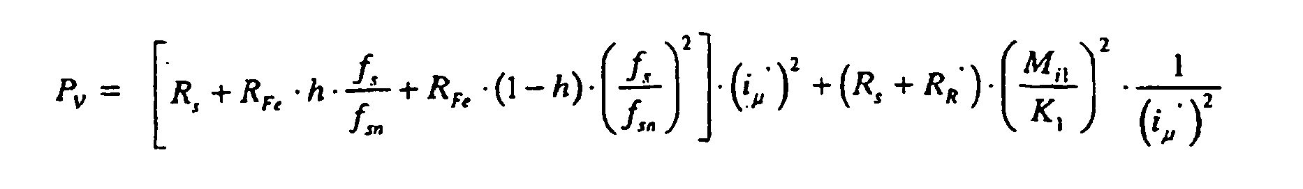
Um im Generatorbetrieb des Spannungsgenerators SG mit möglichst großem Wirkunggrad und somit mit möglichst geringer Belastung der Energiespeicher bzw. Energieversorger arbeiten zu können, sind die elektrischen Verluste sowohl im Umrichter U als auch in der für den Starter-Generator SG vorgesehenen Asynchronmaschine in vorteilhafter Weise dadurch gering gehalten, daß in einer feldorientierten Regelung FOR das innere Moment Mi1 der Asynchronmaschine des Starter-Generators SG nach dem Prinzip der verlustoptimalen Steuerung bzw. Regelung des Rotorflußes durch entsprechende Adaptierung des Magnetisierungsstromes i'u in Abhängigkeit von einem entsprechend dem jeweils geforderten Antriebsdrehmoment ermittelten Wirkstrom isq eingestellt wird.In order to work in the generator mode of the voltage generator SG with the greatest possible degree of effect and thus with the least possible burden of energy storage or energy suppliers, the electrical losses in both the inverter U and provided for the starter-generator SG asynchronous machine advantageously characterized low held that in a field-oriented control FOR the internal moment M i1 of the induction machine of the starter generator SG on the principle of loss-optimal control or regulation of the rotor flux by appropriate adaptation of the magnetizing current i ' u as a function of a corresponding to the respective required drive torque determined active current i sq is set.
Die feldorientierte bzw. rotorflußorientierte Vektorstromregelung einer Asynchronmaschine ist an sich, z.B. durch das Buch "Steuerverfahren für Drehstrommaschinen" von H. Späth, Springer-Verlag, 1983, bekannt.The field-oriented or rotor-flow-oriented vector current control of an asynchronous machine is intrinsically, e.g. by the book "control method for three-phase machines" by H. Späth, Springer-Verlag, 1983, known.
Die feldorientierte Steuerung der Asynchronmaschine geht von der mathematischen Beschreibung des dynamischen Maschinenverhaltens mit Raumzeigergrößen aus. Feldorientierung bedeutet, daß man die frei wählbare Bezugsachse dieses mathematischen Maschinenmodells bezüglich ihrer Winkellage fest mit dem Rotorflußraumzeiger, dem Statorflußraumzeiger oder dem Luftspaltflußraumzeiger verbindet. Die mathematisch einfachste Maschinenstruktur und damit auch die einfachste Struktur einer Steuerung ergeben sich dann, wenn der Rotorflußraumzeiger als Orientierungsgröße gewählt wird. Die Struktur der Maschine gleicht dann bei Vorgabe des Ständerstromraumzeigers der einer fremderregten kompensierten Gleichstrommaschine. Die feldorientierte Steuerung der Asynchronmaschine wird dadurch erreicht, daß man die im feldorientierten Koordinatensystem dargestellten Komponenten des Statorstromzeigers der Maschine als Steuer- bzw. Regelgrößen vorgibt. Mittels einer einfachen Entkopplung werden der Betrag des Flußraumzeigers und das innere Drehmoment unabhängig voneinander steuerbar.The field-oriented control of the asynchronous machine is based on the mathematical description of the dynamic machine behavior with room pointer sizes. Field orientation means that one connects the freely selectable reference axis of this mathematical machine model with respect to their angular position with the Rotorflußraumzeiger, the Statorflußraumzeiger or the Luftspaltflußraumzeiger. The mathematically simplest machine structure and thus also the simplest structure of a control result when the rotor flow space vector is selected as the orientation variable. The structure of the machine then resembles in the specification of the stator current space hand of a separately excited compensated DC machine. The field-oriented control of the asynchronous machine is achieved by predetermining the components of the stator current indicator of the machine, shown in the field-oriented coordinate system, as controlled variables. By means of a simple decoupling, the magnitude of the flux space vector and the internal torque are independently controllable.
Das innere Drehmoment Mi1 ist dann ähnlich wie bei der Regelung einer Gleichstrommaschine bestimmt aus dem Produkt von Wirkstrom isq und adaptiertem Magnetisierungsstrom i'µ ![]()
![]()
Die Verluste einer Asynchronmaschine können wie folgt angegegen werden:![]()
- RS =
- Statorwiderstand
- RR' =
- Auf den Stator umgerechneter Rotorwiderstand
- Rfe =
- Eisenverlustwiderstand
- h =
- Faktor für Hystereseverluste
- l-h =
- Faktor für Wirbelstromverluste
- fs =
- Statorfrequenz
- fSn =
- Statornennfrequenz
- RS =
- stator
- R R '=
- Rotor resistance converted to the stator
- R fe =
- Iron loss resistance
- h =
- Factor for hysteresis losses
- lh =
- Factor for eddy current losses
- fs =
- stator
- f Sn =
- Statornennfrequenz
Der im Sinne eines geringsten Verlustes optimale Magnetisierungsstrom ergibt sich daraus nach folgenden Beziehungen: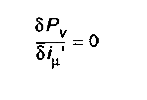
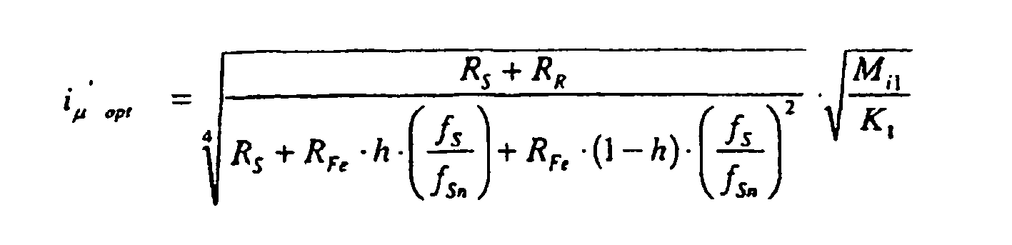

Zur Definition eines für das jeweilige innere Moment Mil maßgeblichen Wirkstrom isq wird von der Differenz zwischen dem Istwertes u2 ist der Zwischenkreisspannung gemäß dem Spannungsniveau des zweiten Bordnetzteiles U2 einerseits und dem Sollwert u2 soll dieser Zwischenkreisspannung ausgegangen und in einem PI-Bildner der entsprechende Wirkstrom isq definiert. Entsprechend dem jeweils geforderten Wirkstrom isq wird gemäß den vorgenanntem Formeln nach dem Prinzip der verlustoptimalen feldorientierten Regelung unter Berücksichtigung der jweiligen Statorfrequenz fS in einem Frequenzadapter FA der entsprechende Magnetisierungsstrom iµ' bestimmt und über die felderorientierte Regelung FOR der Umrichter U bzw. die Asynchronmaschine des Starter-Generators SG angesteuert.For defining a relevant for the respective internal torque M il active current i sq of the difference between the actual value u 2, the intermediate circuit voltage according to the voltage level of the second board power supply U2 on the one hand and the desired value u 2 is to this intermediate circuit voltage is expected, and in a PI-formers of corresponding active current i sq defined. In accordance with the respective required active current i sq , the corresponding magnetizing current i μ 'is determined in accordance with the aforementioned formulas according to the principle of loss-optimal field-oriented regulation f S in a frequency adapter FA and via the field-oriented regulation FOR of the converter U or the asynchronous machine the starter-generator SG driven.
Nach einer weiteren Ausgestaltung der Erfindung wird der Magnetisierungsstrom iµ' in vorteilhafter Weise zusätzlich in Abhängigkeit von einen Begrenzer B gestellt, derart daß der Magnetisierungsstrom bei höherer Drehzahl, insbesondere zur Verhinderung einer thermischen Überlastung bzw. im Sinne eines Feldschwächbetriebes, begrenzbar ist.According to a further embodiment of the invention, the magnetizing current i μ 'is additionally advantageously set as a function of a limiter B, such that the magnetizing current can be limited at a higher rotational speed, in particular to prevent thermal overload or in the sense of a field weakening operation.
Claims (9)
- Onboard electrical system for a motor vehicle- with a first onboard electrical subsystem (U1), in particular one that can be powered from a vehicle battery (B), for supplying power consuming components with a first low voltage,- with a second onboard electrical subsystem (U2) for supplying power consuming components with a second higher voltage, and- with a third onboard electrical subsystem (U3) for the starter mode and/or generator mode of a starter generator (SG) that can be coupled to an internal combustion engine (VB), with a third voltage in starter mode, a switching or connecting device (V1-V3),- with a first connection (V1) from the first onboard electrical subsystem (U1) to the third onboard electrical subsystem (U3), having a device for blocking (D1) in the return direction, via which the first onboard electrical subsystem (U1) can be brought into supply connection across a step-up switching regulator (HSST) to the third onboard electrical subsystem (U3) for the starter mode of the starter-generator (SG);- with a second connection (V2) from the first onboard electrical subsystem (U1) to the second onboard electrical subsystem (U2), with a device for enabling (S2) only during supply of power from the first onboard electrical subsystem (U1) to the second onboard electrical subsystem (U2), via which the first onboard electrical subsystem (U1) can be brought into supply connection across a step-up switching regulator (HSST) to the second onboard electrical subsystem (U2);characterised by- a third connection (V3) from the third onboard electrical subsystem (U3) to the second onboard electrical subsystem (U2), with a device for enabling (S1) only during supply of power from the third onboard electrical subsystem (U3) to the second onboard electrical subsystem (U2) in generator mode, via which the third onboard electrical subsystem (U3) can be brought into supply connection in generator mode of the starter generator (SG) to the second onboard electrical subsystem (U2.
- Onboard electrical system according to claim 1,- wherein the starter-generator (SG) supplies the first onboard electrical subsystem (U1) across the second onboard electrical subsystem (U2) in the generator mode.
- Onboard electrical system according to claim 2,- having a fourth connection (V4) from the second onboard electrical subsystem (U2) to the first onboard electrical subsystem (U1) across a step-down switching regulator (TSST).
- Onboard electrical system according to one of the preceding claims 1-3,- having a converter (U) assigned to the starter-generator (SG) as part of the third onboard electrical subsystem (U3).
- Onboard electrical system according to one of the preceding claims 1 - 4,- having a start capacitor (K) assigned to the starter-generator (SG) as part of the third onboard electrical subsystem (U3).
- Onboard electrical system according to one of the preceding claims 4 or 5,- with the start capacitor (K) also being used as an intermediate circuit capacitor of the converter (U) in generator mode of the starter-generator (SG).
- Onboard electrical system according to at least one of the preceding claims,- with a rotor-flux-oriented, regulated asynchronous motor as the starter-generator (SG).
- Onboard electrical system according to the preceding claim,- with regulation of the internal moment

of the asynchronous machine according to the principle of loss-optimized adaptation of the magnetizing current (i'µ), as a function of a target value effective current (iw) determined according to the respectively required drive torque and the stator frequency (fs). - Onboard electrical system according to at least one of the preceding claims 7 or 8,- having a limiter for limiting the magnetizing current (i'µ) as a function of the rotational speed (n) of the asynchronous machine.
Applications Claiming Priority (3)
| Application Number | Priority Date | Filing Date | Title |
|---|---|---|---|
| DE19752661 | 1997-11-27 | ||
| DE1997152661 DE19752661C2 (en) | 1997-11-27 | 1997-11-27 | Vehicle electrical system for a motor vehicle |
| PCT/DE1998/003354 WO1999028157A1 (en) | 1997-11-27 | 1998-11-16 | Electric system for a motor vehicle |
Publications (3)
| Publication Number | Publication Date |
|---|---|
| EP1034092A1 EP1034092A1 (en) | 2000-09-13 |
| EP1034092B1 EP1034092B1 (en) | 2004-08-18 |
| EP1034092B2 true EP1034092B2 (en) | 2007-12-12 |
Family
ID=7850021
Family Applications (1)
| Application Number | Title | Priority Date | Filing Date |
|---|---|---|---|
| EP98962266A Expired - Lifetime EP1034092B2 (en) | 1997-11-27 | 1998-11-16 | Electric system for a motor vehicle |
Country Status (4)
| Country | Link |
|---|---|
| US (1) | US6320274B1 (en) |
| EP (1) | EP1034092B2 (en) |
| DE (2) | DE19752661C2 (en) |
| WO (1) | WO1999028157A1 (en) |
Families Citing this family (23)
| Publication number | Priority date | Publication date | Assignee | Title |
|---|---|---|---|---|
| DE19953373B4 (en) * | 1999-11-06 | 2004-07-15 | Audi Ag | Device for power supply in a motor vehicle |
| DE19958098C2 (en) * | 1999-12-02 | 2003-04-10 | Trw Automotive Electron & Comp | Power supply for vehicles |
| US6629044B1 (en) * | 2000-03-17 | 2003-09-30 | General Electric Company | Electrical distribution analysis method and apparatus |
| DE10027182C1 (en) * | 2000-05-31 | 2001-10-31 | Siemens Ag | Energy supply device for igniters of restraint device, has master switch supplied via selector switch for at least two energy stores are supplied |
| JP2002036980A (en) * | 2000-07-21 | 2002-02-06 | Toshiba Corp | Car motor driving method and system |
| EP1186463A1 (en) | 2000-08-28 | 2002-03-13 | Siemens Aktiengesellschaft | Method for operating a drive using an internal combustion engine and an electric machine |
| EP1245452A1 (en) | 2001-03-30 | 2002-10-02 | Siemens Aktiengesellschaft | Vehicle on-board network, particularly for a truck |
| US20030197991A1 (en) * | 2002-04-08 | 2003-10-23 | Visteon Global Technologies, Inc. | System for providing power to an electrical system in a vehicle |
| EP1363379A3 (en) * | 2002-05-13 | 2004-01-02 | Luxon Energy Devices Corporation | Power module for generating impulses of various levels |
| EP1424494A1 (en) * | 2002-11-27 | 2004-06-02 | Continental ISAD Electronic Systems GmbH & Co. oHG | Hybrid propulsion system and method for conjoint application of propulsion torque |
| JP4709847B2 (en) * | 2004-11-11 | 2011-06-29 | インターナショナル・ビジネス・マシーンズ・コーポレーション | Parallel flushing of processing units by network reconfiguration |
| FR2878088B1 (en) * | 2004-11-18 | 2007-03-30 | Renault Sas | MULTI-VOLTAGE POWER SUPPLY SYSTEM FOR A DRIVING NETWORK OF A MOTOR VEHICLE |
| DE102004062939B4 (en) * | 2004-12-28 | 2019-02-21 | Volkswagen Ag | Method and device for optimized starting of an internal combustion engine |
| DE102005015658A1 (en) * | 2005-04-06 | 2007-01-11 | Bayerische Motoren Werke Ag | Switching device for linking different electrical voltage levels in a motor vehicle |
| US20080288132A1 (en) | 2007-05-16 | 2008-11-20 | General Electric Company | Method of operating vehicle and associated system |
| US7889524B2 (en) | 2007-10-19 | 2011-02-15 | Illinois Institute Of Technology | Integrated bi-directional converter for plug-in hybrid electric vehicles |
| WO2009062227A1 (en) * | 2007-11-14 | 2009-05-22 | Renergyx Pty Limited | Electrical energy and distribution system |
| FR2945996B1 (en) | 2009-05-29 | 2012-10-12 | Peugeot Citroen Automobiles Sa | ELECTRIC POWER SUPPLY SYSTEM OF A THERMAL MOTOR VEHICLE PROVIDED WITH AN AUTOMATIC STOP AND RESTART DEVICE |
| JP5297953B2 (en) | 2009-09-08 | 2013-09-25 | トヨタ自動車株式会社 | Electric motor drive system for electric vehicle |
| DE102010047017A1 (en) * | 2010-09-30 | 2012-04-05 | Voith Patent Gmbh | Method for controlling converter-fed asynchronous machine for hybrid system used in hybrid vehicle, involves determining end of rotation torque request for machine, and reducing magnetic flux of machine after certain period |
| DE102013009801A1 (en) * | 2013-06-12 | 2014-12-18 | Audi Ag | Motor vehicle with two electrical systems with different vehicle electrical system voltages |
| US10479218B2 (en) | 2017-02-14 | 2019-11-19 | Toyota Motor Engineering & Manufacturing North America, Inc. | Electric vehicle power system with shared converter |
| JP6989539B2 (en) * | 2019-01-21 | 2022-01-05 | 本田技研工業株式会社 | vehicle |
Citations (2)
| Publication number | Priority date | Publication date | Assignee | Title |
|---|---|---|---|---|
| DE3812577A1 (en) † | 1988-04-15 | 1989-10-26 | Bosch Gmbh Robert | ON-BOARD NETWORK FOR A MOTOR VEHICLE |
| WO1997008456A1 (en) † | 1995-08-31 | 1997-03-06 | Isad Electronic Systems Gmbh & Co. Kg | Starter/generator for an internal combustion engine, in particular a vehicle engine |
Family Cites Families (8)
| Publication number | Priority date | Publication date | Assignee | Title |
|---|---|---|---|---|
| US4672294A (en) * | 1986-01-24 | 1987-06-09 | Peter Norton | Dual battery system with improved overvoltage protection |
| US4723079A (en) * | 1986-03-27 | 1988-02-02 | Peter Norton | Vehicle power supply with regulated voltage and adjustable voltage outputs |
| DE3743317A1 (en) * | 1987-12-21 | 1989-06-29 | Bosch Gmbh Robert | VEHICLE WIRE NETWORK SYSTEM |
| DE3743316A1 (en) * | 1987-12-21 | 1989-06-29 | Bosch Gmbh Robert | VEHICLE WIRE NETWORK SYSTEM |
| US5175439A (en) * | 1987-12-21 | 1992-12-29 | Robert Bosch Gmbh | Power supply circuit for motor vehicles |
| JP3039119B2 (en) * | 1992-03-31 | 2000-05-08 | 日産自動車株式会社 | Power supply for vehicles |
| JP3516361B2 (en) * | 1995-01-17 | 2004-04-05 | 富士重工業株式会社 | Power supply for vehicles |
| DE19646043A1 (en) * | 1996-11-08 | 1998-05-14 | Bosch Gmbh Robert | Power supply device |
-
1997
- 1997-11-27 DE DE1997152661 patent/DE19752661C2/en not_active Revoked
-
1998
- 1998-11-16 DE DE59811843T patent/DE59811843D1/en not_active Expired - Lifetime
- 1998-11-16 WO PCT/DE1998/003354 patent/WO1999028157A1/en active IP Right Grant
- 1998-11-16 EP EP98962266A patent/EP1034092B2/en not_active Expired - Lifetime
-
2000
- 2000-05-30 US US09/580,550 patent/US6320274B1/en not_active Expired - Fee Related
Patent Citations (2)
| Publication number | Priority date | Publication date | Assignee | Title |
|---|---|---|---|---|
| DE3812577A1 (en) † | 1988-04-15 | 1989-10-26 | Bosch Gmbh Robert | ON-BOARD NETWORK FOR A MOTOR VEHICLE |
| WO1997008456A1 (en) † | 1995-08-31 | 1997-03-06 | Isad Electronic Systems Gmbh & Co. Kg | Starter/generator for an internal combustion engine, in particular a vehicle engine |
Also Published As
| Publication number | Publication date |
|---|---|
| US6320274B1 (en) | 2001-11-20 |
| EP1034092B1 (en) | 2004-08-18 |
| WO1999028157A1 (en) | 1999-06-10 |
| DE59811843D1 (en) | 2004-09-23 |
| DE19752661C2 (en) | 2001-09-13 |
| DE19752661A1 (en) | 1999-06-10 |
| EP1034092A1 (en) | 2000-09-13 |
Similar Documents
| Publication | Publication Date | Title |
|---|---|---|
| EP1034092B2 (en) | Electric system for a motor vehicle | |
| DE60319570T2 (en) | HYBRID MOTOR VEHICLE WITH CONTROL DEVICE FOR CHARGING THE BATTERY | |
| DE60119419T2 (en) | Device for controlling a permanent magnet motor, either as a starter or as a generator in a motor vehicle | |
| EP2541755B1 (en) | Drive device for a vehicle | |
| DE102010001250B4 (en) | On-board electrical system and method for operating an on-board electrical system | |
| DE10231379B3 (en) | Drive system for a motor vehicle with an internal combustion engine and an electric machine | |
| DE102004057693B4 (en) | Device for rapid discharge of a capacitor | |
| EP2365919A1 (en) | Operating arrangement for an electrically operated vehicle | |
| EP0875089A1 (en) | Power supply system | |
| EP1386389A1 (en) | Device for power supply in a multi-voltage electric system of a motor vehicle | |
| EP0929927B1 (en) | Method for regulating a generator | |
| EP2707245B1 (en) | Power electronics apparatus and control method for an electric machine and for electrical energy stores | |
| DE102010017417A1 (en) | Electric supply and starting system for a motor vehicle and method for operating the electrical supply and starting system | |
| DE19838296B4 (en) | Electrical power supply system | |
| WO2016041711A1 (en) | Electrical system for a vehicle which can be electrically driven | |
| WO2004006422A1 (en) | Automotive on-board supply system | |
| EP2157313A2 (en) | Device and method for starter support in a motor vehicle | |
| EP1410482B1 (en) | Drive for a motor vehicle | |
| EP1313628B1 (en) | Method for operating a drive with an internal combustion engine and an electric machine | |
| DE102013206296A1 (en) | Method for operating a power supply unit for a motor vehicle electrical system | |
| DE102010025266A1 (en) | Transport vehicle with a plurality of electrical machines | |
| DE102010019151B4 (en) | Method and device for energy transmission in a motor vehicle | |
| DE102004040228B4 (en) | Electric vehicle | |
| WO2003099605A1 (en) | Drive system for a motor vehicle comprising an internal combustion engine and an electric motor | |
| DE102011086734B4 (en) | Method for operating an energy supply unit for an on-board electrical system of a motor vehicle |
Legal Events
| Date | Code | Title | Description |
|---|---|---|---|
| PUAI | Public reference made under article 153(3) epc to a published international application that has entered the european phase |
Free format text: ORIGINAL CODE: 0009012 |
|
| 17P | Request for examination filed |
Effective date: 20000417 |
|
| AK | Designated contracting states |
Kind code of ref document: A1 Designated state(s): DE FR GB IT |
|
| 17Q | First examination report despatched |
Effective date: 20030919 |
|
| GRAP | Despatch of communication of intention to grant a patent |
Free format text: ORIGINAL CODE: EPIDOSNIGR1 |
|
| GRAA | (expected) grant |
Free format text: ORIGINAL CODE: 0009210 |
|
| GRAS | Grant fee paid |
Free format text: ORIGINAL CODE: EPIDOSNIGR3 |
|
| AK | Designated contracting states |
Kind code of ref document: B1 Designated state(s): DE FR GB IT |
|
| REG | Reference to a national code |
Ref country code: GB Ref legal event code: FG4D Free format text: NOT ENGLISH |
|
| GBT | Gb: translation of ep patent filed (gb section 77(6)(a)/1977) |
Effective date: 20040818 |
|
| REF | Corresponds to: |
Ref document number: 59811843 Country of ref document: DE Date of ref document: 20040923 Kind code of ref document: P |
|
| PLAQ | Examination of admissibility of opposition: information related to despatch of communication + time limit deleted |
Free format text: ORIGINAL CODE: EPIDOSDOPE2 |
|
| PLBQ | Unpublished change to opponent data |
Free format text: ORIGINAL CODE: EPIDOS OPPO |
|
| PLBI | Opposition filed |
Free format text: ORIGINAL CODE: 0009260 |
|
| ET | Fr: translation filed | ||
| PLAX | Notice of opposition and request to file observation + time limit sent |
Free format text: ORIGINAL CODE: EPIDOSNOBS2 |
|
| 26 | Opposition filed |
Opponent name: CONTI TEMIC MICROELECTRONIC GMBH Effective date: 20050510 |
|
| PLAF | Information modified related to communication of a notice of opposition and request to file observations + time limit |
Free format text: ORIGINAL CODE: EPIDOSCOBS2 |
|
| PLBB | Reply of patent proprietor to notice(s) of opposition received |
Free format text: ORIGINAL CODE: EPIDOSNOBS3 |
|
| PUAH | Patent maintained in amended form |
Free format text: ORIGINAL CODE: 0009272 |
|
| STAA | Information on the status of an ep patent application or granted ep patent |
Free format text: STATUS: PATENT MAINTAINED AS AMENDED |
|
| 27A | Patent maintained in amended form |
Effective date: 20071212 |
|
| AK | Designated contracting states |
Kind code of ref document: B2 Designated state(s): DE FR GB IT |
|
| RAP2 | Party data changed (patent owner data changed or rights of a patent transferred) |
Owner name: SIEMENS VDO AUTOMOTIVE AG |
|
| GBTA | Gb: translation of amended ep patent filed (gb section 77(6)(b)/1977) | ||
| REG | Reference to a national code |
Ref country code: GB Ref legal event code: 732E |
|
| REG | Reference to a national code |
Ref country code: FR Ref legal event code: TP |
|
| ET3 | Fr: translation filed ** decision concerning opposition | ||
| PGFP | Annual fee paid to national office [announced via postgrant information from national office to epo] |
Ref country code: IT Payment date: 20081122 Year of fee payment: 11 |
|
| PGFP | Annual fee paid to national office [announced via postgrant information from national office to epo] |
Ref country code: FR Payment date: 20081113 Year of fee payment: 11 |
|
| PGFP | Annual fee paid to national office [announced via postgrant information from national office to epo] |
Ref country code: GB Payment date: 20081117 Year of fee payment: 11 |
|
| GBPC | Gb: european patent ceased through non-payment of renewal fee |
Effective date: 20091116 |
|
| REG | Reference to a national code |
Ref country code: FR Ref legal event code: ST Effective date: 20100730 |
|
| PG25 | Lapsed in a contracting state [announced via postgrant information from national office to epo] |
Ref country code: FR Free format text: LAPSE BECAUSE OF NON-PAYMENT OF DUE FEES Effective date: 20091130 |
|
| PG25 | Lapsed in a contracting state [announced via postgrant information from national office to epo] |
Ref country code: GB Free format text: LAPSE BECAUSE OF NON-PAYMENT OF DUE FEES Effective date: 20091116 |
|
| PG25 | Lapsed in a contracting state [announced via postgrant information from national office to epo] |
Ref country code: IT Free format text: LAPSE BECAUSE OF NON-PAYMENT OF DUE FEES Effective date: 20091116 |
|
| PGFP | Annual fee paid to national office [announced via postgrant information from national office to epo] |
Ref country code: DE Payment date: 20121130 Year of fee payment: 15 |
|
| REG | Reference to a national code |
Ref country code: DE Ref legal event code: R119 Ref document number: 59811843 Country of ref document: DE Effective date: 20140603 |
|
| PG25 | Lapsed in a contracting state [announced via postgrant information from national office to epo] |
Ref country code: DE Free format text: LAPSE BECAUSE OF NON-PAYMENT OF DUE FEES Effective date: 20140603 |