EP0899353B1 - Method of sintering an iron-based high-hardness glassy alloy - Google Patents
Method of sintering an iron-based high-hardness glassy alloy Download PDFInfo
- Publication number
- EP0899353B1 EP0899353B1 EP98306496A EP98306496A EP0899353B1 EP 0899353 B1 EP0899353 B1 EP 0899353B1 EP 98306496 A EP98306496 A EP 98306496A EP 98306496 A EP98306496 A EP 98306496A EP 0899353 B1 EP0899353 B1 EP 0899353B1
- Authority
- EP
- European Patent Office
- Prior art keywords
- alloy
- sintering
- temperature
- glassy alloy
- glassy
- Prior art date
- Legal status (The legal status is an assumption and is not a legal conclusion. Google has not performed a legal analysis and makes no representation as to the accuracy of the status listed.)
- Expired - Lifetime
Links
Images


Classifications
-
- C—CHEMISTRY; METALLURGY
- C22—METALLURGY; FERROUS OR NON-FERROUS ALLOYS; TREATMENT OF ALLOYS OR NON-FERROUS METALS
- C22C—ALLOYS
- C22C33/00—Making ferrous alloys
- C22C33/02—Making ferrous alloys by powder metallurgy
- C22C33/0257—Making ferrous alloys by powder metallurgy characterised by the range of the alloying elements
-
- A—HUMAN NECESSITIES
- A63—SPORTS; GAMES; AMUSEMENTS
- A63B—APPARATUS FOR PHYSICAL TRAINING, GYMNASTICS, SWIMMING, CLIMBING, OR FENCING; BALL GAMES; TRAINING EQUIPMENT
- A63B53/00—Golf clubs
- A63B53/04—Heads
-
- A—HUMAN NECESSITIES
- A63—SPORTS; GAMES; AMUSEMENTS
- A63B—APPARATUS FOR PHYSICAL TRAINING, GYMNASTICS, SWIMMING, CLIMBING, OR FENCING; BALL GAMES; TRAINING EQUIPMENT
- A63B53/00—Golf clubs
- A63B53/04—Heads
- A63B53/0466—Heads wood-type
-
- A—HUMAN NECESSITIES
- A63—SPORTS; GAMES; AMUSEMENTS
- A63B—APPARATUS FOR PHYSICAL TRAINING, GYMNASTICS, SWIMMING, CLIMBING, OR FENCING; BALL GAMES; TRAINING EQUIPMENT
- A63B53/00—Golf clubs
- A63B53/04—Heads
- A63B53/047—Heads iron-type
-
- A—HUMAN NECESSITIES
- A63—SPORTS; GAMES; AMUSEMENTS
- A63B—APPARATUS FOR PHYSICAL TRAINING, GYMNASTICS, SWIMMING, CLIMBING, OR FENCING; BALL GAMES; TRAINING EQUIPMENT
- A63B53/00—Golf clubs
- A63B53/10—Non-metallic shafts
-
- A—HUMAN NECESSITIES
- A63—SPORTS; GAMES; AMUSEMENTS
- A63B—APPARATUS FOR PHYSICAL TRAINING, GYMNASTICS, SWIMMING, CLIMBING, OR FENCING; BALL GAMES; TRAINING EQUIPMENT
- A63B60/00—Details or accessories of golf clubs, bats, rackets or the like
-
- C—CHEMISTRY; METALLURGY
- C22—METALLURGY; FERROUS OR NON-FERROUS ALLOYS; TREATMENT OF ALLOYS OR NON-FERROUS METALS
- C22C—ALLOYS
- C22C45/00—Amorphous alloys
- C22C45/02—Amorphous alloys with iron as the major constituent
-
- C—CHEMISTRY; METALLURGY
- C22—METALLURGY; FERROUS OR NON-FERROUS ALLOYS; TREATMENT OF ALLOYS OR NON-FERROUS METALS
- C22C—ALLOYS
- C22C47/00—Making alloys containing metallic or non-metallic fibres or filaments
- C22C47/14—Making alloys containing metallic or non-metallic fibres or filaments by powder metallurgy, i.e. by processing mixtures of metal powder and fibres or filaments
-
- A—HUMAN NECESSITIES
- A63—SPORTS; GAMES; AMUSEMENTS
- A63B—APPARATUS FOR PHYSICAL TRAINING, GYMNASTICS, SWIMMING, CLIMBING, OR FENCING; BALL GAMES; TRAINING EQUIPMENT
- A63B2209/00—Characteristics of used materials
-
- A—HUMAN NECESSITIES
- A63—SPORTS; GAMES; AMUSEMENTS
- A63B—APPARATUS FOR PHYSICAL TRAINING, GYMNASTICS, SWIMMING, CLIMBING, OR FENCING; BALL GAMES; TRAINING EQUIPMENT
- A63B53/00—Golf clubs
- A63B53/04—Heads
- A63B53/0416—Heads having an impact surface provided by a face insert
-
- A—HUMAN NECESSITIES
- A63—SPORTS; GAMES; AMUSEMENTS
- A63B—APPARATUS FOR PHYSICAL TRAINING, GYMNASTICS, SWIMMING, CLIMBING, OR FENCING; BALL GAMES; TRAINING EQUIPMENT
- A63B53/00—Golf clubs
- A63B53/04—Heads
- A63B53/0487—Heads for putters
-
- A—HUMAN NECESSITIES
- A63—SPORTS; GAMES; AMUSEMENTS
- A63B—APPARATUS FOR PHYSICAL TRAINING, GYMNASTICS, SWIMMING, CLIMBING, OR FENCING; BALL GAMES; TRAINING EQUIPMENT
- A63B53/00—Golf clubs
- A63B53/12—Metallic shafts
-
- A—HUMAN NECESSITIES
- A63—SPORTS; GAMES; AMUSEMENTS
- A63B—APPARATUS FOR PHYSICAL TRAINING, GYMNASTICS, SWIMMING, CLIMBING, OR FENCING; BALL GAMES; TRAINING EQUIPMENT
- A63B60/00—Details or accessories of golf clubs, bats, rackets or the like
- A63B60/48—Details or accessories of golf clubs, bats, rackets or the like with corrugated cross-section
-
- B—PERFORMING OPERATIONS; TRANSPORTING
- B22—CASTING; POWDER METALLURGY
- B22F—WORKING METALLIC POWDER; MANUFACTURE OF ARTICLES FROM METALLIC POWDER; MAKING METALLIC POWDER; APPARATUS OR DEVICES SPECIALLY ADAPTED FOR METALLIC POWDER
- B22F2998/00—Supplementary information concerning processes or compositions relating to powder metallurgy
-
- B—PERFORMING OPERATIONS; TRANSPORTING
- B22—CASTING; POWDER METALLURGY
- B22F—WORKING METALLIC POWDER; MANUFACTURE OF ARTICLES FROM METALLIC POWDER; MAKING METALLIC POWDER; APPARATUS OR DEVICES SPECIALLY ADAPTED FOR METALLIC POWDER
- B22F3/00—Manufacture of workpieces or articles from metallic powder characterised by the manner of compacting or sintering; Apparatus specially adapted therefor ; Presses and furnaces
- B22F3/10—Sintering only
Definitions
- the present invention relates to a method of producing a sintered bulk glassy alloy using spark plasma sintering.
- Some kinds of multi-element alloy have a property of not crystallizing when a composition is quenched from a molten state, and transferring to a vitreous solid via a supercooled liquid state having a certain temperature range.
- a non-crystalline alloy falling under this category is known as a glassy alloy.
- amorphous alloys include an Fe-P-C-system non-crystalline alloy manufactured for the first time in the 1960s, an (Fe, Co, Ni)-P-B-system and an (Fe, Co, Ni)-Si-B-system non-crystalline alloys manufactured in the 1970s, and an (Fe, Co, Ni)-M(Zr, Hf, Nb)- system non-crystalline alloy and an (Fe, Co, Ni)-M(Zr, Hf, Nb)-B-system non-crystalline alloy manufactured in the 1980s. These alloys, having magnetism, were expected to be applied as non-crystalline magnetic materials.
- any of the conventional amorphous alloys has a tight temperature range in the supercooled liquid state, a non-crystalline product cannot be formed unless it is quenched at a high cooling rate on a level of 10 5 °C/s by the application of a method known as the single roll process.
- the product manufactured by quenching by the single roll process took a shape of a thin strip having a thickness of up to about 50 ⁇ m, and a bulk-shaped non-crystalline solid was unavailable.
- a sinter is obtained by crushing the thin strip resulting from the application of the liquid quenching process, and sintering the crushed strip under pressure in a sealed space.
- the sinter produced from the conventional amorphous alloy is porous and brittle, and is not applicable as a part subjected to stress such as a gear, a milling head, a golf club head or a golf club shaft.
- Glassy alloys known as having a relatively wide temperature range in the supercooled liquid state, and giving a non-crystalline solid through slower cooling include Ln-Al-TM, Mg-Ln-TM, ZR-Ln-TM (where, Ln is a rare-earth element, and TM is a transition metal)-based alloys developed during the period of 1988 through 1991.
- Non-crystalline solids having a thickness of several mm available from these glassy alloys have special compositions in all cases and contain rare-earth elements, resulting in a high cost, and no sufficient study is made regarding applications.
- the head portion of a wood-type golf club is usually manufactured with a metal such as stainless steel, an aluminum alloy or a titanium alloy as a material, and the resultant metal wood forms the main current in the market.
- a metal such as stainless steel, an aluminum alloy or a titanium alloy as a material
- the resultant metal wood forms the main current in the market.
- the metal would provide an advantage of a very high degree of freedom in designing the head.
- iron-type golf club also iron (soft iron), stainless steel, carbon, titanium alloy and various other materials are used for the head.
- iron soft iron
- stainless steel titanium alloy
- duralumin various other materials are applicable.
- the carbon shaft excellent in lightness and easiness to handle forms the main current in place of the conventional steel shaft.
- the carbon shaft have advantage of a high degree of freedom in design, and various kinds of shaft are now commercially available, including those for frail women and for professional golfers.
- An aluminum alloy used for a golf clubhead is generally believed manufacturable into a large head because of a high specific gravity, but inferior to a stainless steel or titanium alloy head in yardage.
- a titanium alloy which is suitable as a material for a golf club because of a high strength and an excellent repellent force, must be fabricated in a vacuum or in an inert gas and the yield is low, resulting in a very high unit cost of a head.
- the head made of soft iron has defects of a relatively large specific gravity and easy susceptibility to flaws.
- a stainless steel head which is excellent in durability, does not permit adjustment if the lie angle or the loft angle, and is kept at arm's length by senior golfers.
- a head made of a titanium alloy is defective in that fabrication requires much time and labor, leading to a very high unit cost as described above.
- a carbon head is far more susceptible to flaws and handling must be careful.
- a putter-type golf club should preferably be provided simultaneously with appropriate bounce and weight, but a material satisfying these requirements has not as yet been existent.
- a carbon shaft for a golf club has generally a configuration in which it comprises an inner layer obtained by aligning carbon fiber groups in a direction, impregnating the same with a thermosetting synthetic resin and forming the same into a tubular shape, and an outer layer available by aligning fine line or filament-shaped alloy groups in a direction, impregnating the same with a thermosetting synthetic resin, and forming the same.
- the alloy used for the outer layer has an important effect on properties of the carbon shaft. In order to manufacture a shaft light in weight, it is necessary to make the alloy of the outer layer finer, but this results in a lower strength. In order to increase strength, it suffices to use larger alloy lines, but this leads to a larger weight.
- EP-A-0747498 discloses a bulk ferrous metal glassy alloy.
- a high-hardness material having excellent properties as parts having surface fine irregularities such as a gear, a milling head, a golf club head and a golf club shaft
- the present inventors found that a certain glassy alloy had a relatively wide temperature range in the supercooled state, was capable of being manufactured into a bulk-shape non-crystalline solid product, and gave a very high-hardness non-crystalline solid product. Further, possibly was found to manufacture a high-hardness parts having fine surface irregularities by sintering powder of this glassy alloy at a sintering temperature near the crystallization temperature or casting the same in a mold, thus arriving at development of the present invention.
- the present invention was developed in a view of the above-mentioned circumstances, and has an object to provide a high-hardness sinter or casting having fine surface irregularities manufactured from a glassy alloy permitting formation of a high-hardness bulk-shaped non-crystalline form.
- the sinter of the present invention is produced according to the claim.
- a method of producing a sintered bulk glassy alloy comprising spark plasma sintering a high-hardness glassy alloy at a temperature of at least 300°C, the alloy composition in atomic % being:
- the manufacturing method may preferrably comprise the steps of applying a heat treatment to the same so that at least a part thereof is crystallized.
- a crystalline phase precipitated through a crystallization treatment shall also be called a glassy alloy.
- An alloy having ⁇ Tx is called a glassy alloy and one not having ⁇ Tx is called an amorphous for discrimination.
- a glassy alloy having a temperature interval ⁇ Tx of the supercooled liquid as expressed by the formula ⁇ Tx Tx - Tg (where, Tx is a crystallization temperature, and Tg is the glass transition temperature) is employed in the invention.
- Applicable glassy alloys include metal-metalloid glassy alloys and metal-metal glassy alloys, as given in the claim.
- the above-mentioned metal-metalloid glassy alloy has a temperature interval ⁇ Tx of the supercooled liquid of at least 35°C, or in some compositions, a remarkable temperature interval of 40 to 50°C. This has never been foreseen from the Fe-based alloys known from the conventional findings.
- the present invention gives a bulk-shaped one which is far more excellent in practical merits.
- the metal-metalloid glassy alloy used in the invention is given in the claim.
- the Si content should preferably be up to 15% since a higher Si content causes disappearance of ⁇ Tx in the supercooled liquid region.
- composition of the metal-metalloid glassy alloy claimed comprises, in atomic %, from 1 to 10% Al, 0.5 to 4% Ga, from 0 to 15% P, from 2 to 7% C, from 2 to 10% B, from 0 to 15% Si and the balance Fe, and may contain incidental impurities.
- the composition should preferably include from 6 to 15% P and from 2 to 7% C, and this gives a value of ⁇ Tx in the supercooled liquid region of at least 35°C.
- Fig. 1 is a perspective view illustrating a gear manufactured by a manufacturing method of a part having fine surface irregularities.
- the gear 1 is manufactured by sintering the powder of the above-mentioned glassy alloy.
- the gear 1 has teeth (fine irregularities) 2 on the outer periphery thereof.
- Fig. 2 illustrates main portions of a typical spark plasma sintering machine suitably used for manufacturing the gear 1.
- the spark plasma sintering machine of this example mainly comprises a cylindrical forming mold 41, an upper punch 42 and a lower punch 43 for pressing a raw material powder (powder particles) charged in this forming mold 41, a punch electrode 44 supporting the lower punch 43 and serving as an electrode on one side when feeding pulse current as described later, another punch electrode 45 pressing down the upper punch 42 and serving as another electrode for feeding pulse current, and a thermocouple 47 for measuring temperature of the powder raw material held between the upper and the lower punches 42 and 43.
- Fine surface irregularities 41a are formed on the inner surface of the forming mold 41 as shown in Fig.
- a cavity formed by the upper and the lower punches 42 and 43 and the forming mold 41 in the interior of this spark plasma sintering machine has a shape substantially in agreement with the shape of the target formed product (shape of the gear 1 in this embodiment).
- reference numeral 41b represents a core rod.
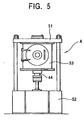
- Fig. 5 illustrates an overall configuration of the above-mentioned spark plasma sintering machine.
- the spark plasma sintering machine A is a kind of spark plasma sintering machine called Model SPS-2050 manufactured by Sumitomo Cool Mining Co., Ltd., and has the main portions of which the structure is shown in Fig. 2.
- the machine shown in Fig. 5 has an upper base 51 and a lower base 52, a chamber 53 provided in contact with the upper base 51, and most of the structure shown in Fig. 2 are housed in this chamber 53.
- the chamber 53 is connected to a vacuum evacuation unit and an atmospheric gas feeding unit not shown, and a raw metal powder (powder particles) 46 to be charged between the upper and the lower punches 42 and 43 can be held in a desired atmosphere such as an inert gas atmosphere.
- a raw metal powder (powder particles) 46 to be charged between the upper and the lower punches 42 and 43 can be held in a desired atmosphere such as an inert gas atmosphere.
- an energizing unit is omitted in Figs. 2 and 5
- another energizing unit separately provided is connected to the upper and the lower punches 42 and 43 and the punch electrodes 44 and 45 so that pulse current as shown in Fig. 5 can be fed from this energizing unit via the punches 42 and 43 and the punch electrodes
- a raw material powder for forming 46 should be prepared.
- a manufacturing process of the raw material powder 46 comprises the step, for example, of preparing a single-element powder or single-element lumps for each of the components of the glassy alloy (may be partially alloyed in advance), mixing these single-element powder and single-element lumps, the melting the resultant mixed powder in an inert gas atmosphere such as Ar gas in a melting unit such as a crucible to obtain an alloy melt having a prescribed composition, forming a bulk-shaped, ribbon-shaped, linear or powdery shape by the casting, process of pouring the alloy melt into a mold and slowly cooling the same, by the quenching process of using a single roll or dual rolls, by the wet spinning process, by the solution extracting process, or by high-pressure gas spraying process, and the pulverizing the resultant product other than powder.
- an inert gas atmosphere such as Ar gas
- a melting unit such as a crucible
- the subsequent steps comprise charging the powder into a forming mold 41 provided between the upper and the lower punches 42 and 43 of the spark plasma sintering machine, vacuum-evacuating the interior of the chamber 53, conducting forming by applying a pressure from above and below with the punches 42 and 43, impressing a pulse current as shown, for example, in Fig. 4 to the raw material powder 46 for heating and forming.
- a pulse current as shown, for example, in Fig. 4
- this spark plasma sintering it is possible to heat the raw material powder 46 rapidly at a prescribed heating rate with the supplied current, and to strictly control temperature of the raw material powder 46 in response to the value of supplied current. It is therefore possible to perform temperature control far more accurately than in heating with a heater, thus permitting sintering under conditions close to ideal ones as preciously designed.
- a sintering temperature of at least 300°C is required for ensuring solidification and forming of the raw material powder. Since the glassy alloy used as the raw material powder has a large value of temperature interval ⁇ Tx(Tx-Tg) of the supercooled liquid, a high-density sinter is suitably available by conducting sintering under pressure by the utilization of viscous flow generated at a temperature within a range of from Tg to Tx.
- the monitored sintering temperature is the temperature of the thermocouple provided in the die, resulting in a temperature lower than that to which the powder sample is exposed.
- the heating rate for sintering should preferably be at least 10°/minute.
- the pressure in sintering should preferably be at least 3 tons/cm 2 because a sinter cannot be formed under a lower pressure.
- a heat treatment for annealing or partial crystallization may be applied to the resultant sinter.
- the heat treatment temperature in this case when heat-treating a metal-metalloid glassy alloy, should preferably be within a range of from 300 to 500°, or more preferably, from 300 to 450°C.
- temperature should preferably within a range of from 427°C (700 K) to 627°C (900 K), or more preferably, from 477°C (750 K) to 523°C (800 K).
- a suitable cooling rate is determined, depending upon the alloy composition, means for manufacture thereof, the size of the product and the shape thereof.
- a gear 1 comprising a bulk-shaped sinter is available by filling a forming mold 41 having fine irregularities 41a with the powder (raw material powder) 46 of the above-mentioned glassy alloy, and sintering the powder 46 of the glassy alloy at a sintering temperature near the crystallization-temperature.
- the above-mentioned glassy alloy has a very broad temperature interval ⁇ Tx of the supercooled liquid region, permits manufacture of a bulk-shaped sinter having a thickness sufficient to apply to a gear, and manufacture of a high-hardness sinter.
- the gear 1 comprising the sinter obtained by the foregoing method has the same chemical composition as the glassy alloy used as the raw material powder, exhibits a high hardness, and can have a further improved hardness through a heat treatment.
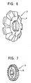
- Fig. 6 is a perspective view illustrating a gear cutter manufactured by the manufacturing method of a part having fine surface irregularities.
- This gear cutter 3 is manufactured by sintering the powder of the above-mentioned glassy alloy.
- the gear cutter 3 has a cutting edge (fine irregularities) on the outer periphery.
- This gear cutter 3 can be manufactured in the same manner as in the above-mentioned manufacturing method of a gear except for the use of a forming mold having fine irregularities formed on the inner surface in response to the shape of the gear cutter, of the spark plasma sintering machine.
- the gear cutter 3 thus obtained has the same composition as the glassy alloy used as the raw material powder, exhibits a high hardness, and can have a further improved hardness through a heat treatment.
- the cutting edge 4 of the gear cutter 3 should preferably be polished for finding.
- Fig. 7 is a perspective view illustrating a side milling cutter manufactured by the manufacturing method of a part having fine irregularities.
- This side milling cutter 5 is manufactured by sintering the powder of the above-mentioned glassy alloy.
- the side milling cutter 5 has a cutting edge (fine irregularities) on the outer periphery.
- the side milling cutter 5 can be manufactured in the same manner as in the above-mentioned manufacturing method of a gear except for the use of a forming mold having fine irregularities formed on the inner surface in response to the shape of the side milling cutter, of the spark plasma sintering machine.
- the side milling cutter 5 thus obtained has the same composition as the glassy alloy used as the raw material powder, exhibits a high hardness, and can have a further improved hardness through a heat treatment.
- the cutting edge 6 of the side milling cutter 5 should preferably be polished for finishing.
- the product can be formed by clog-forging by the heating it to a temperature within a range of from Tg to Tx.
- Fig. 8 a perspective view illustrating a first golf club head.
- the entire head is composed of a high-hardness glassy alloy. This gives an improved bounce sufficient to ensure a longer yardage. Even when the sole portion rubs the ground upon swinging, the head is hardly damaged. Since even contact with other club or the like does not easily cause flaws, a good exterior view can be kept for a longer period of time.
- Fig. 9 is an exploded view illustrating a second golf clubhead. This has a configuration in which a face portion 13 is fitted to, and fixed to, an opening 12 provided in the wood-type golf clubhead main body 11.
- a golf clubhead of the invention is available by making this wood-type golf clubhead main body 11 with a conventional material such as stainless steel, and making only the face portion 13 with a glassy alloy.
- Fig. 10 is a perspective view illustrating a third golf clubhead.
- the entire head is made of the above-mentioned glassy alloy.
- the entire head is composed of a high-hardness glassy alloy. This gives an improved bounce sufficient to ensure a longer yardage. Even when the sole portion rubs the ground upon swinging, the head is hardly damaged. Since even contact with the other club or the like does not easily cause flaws, a good exterior view can be kept for a longer period of time.
- FIG. 11 is an exploded view illustrating a fourth golf clubhead has a configuration in which a face portion 17 is fitted to, and fixed to, an opening 16 provided in the iron-type golf clubhead main body 15.
- a golf clubhead is available by making this iron-type golf clubhead main body 15 with a conventional material such as stainless steel, and making only the face portion 17 with a glassy alloy.
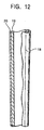
- Fig. 12 is a partial sectional view illustrating a golf club shaft of the invention.
- This golf club shaft 18 comprises an inner layer 19 formed into a tubular shape by impregnating carbon fiber groups aligned in a direction with a thermosetting synthetic resin, and an outer layer 20 formed by impregnating fine line or filament-shaped alloy groups aligned in a direction with a thermosetting synthetic resin.
- Shaft strength can be improved by composing the fine line or filament-shaped alloy groups with a high-hardness glassy alloy, and further, because strength is not improved by increasing fine line thickness, an increase in the shaft weight is inhibited.
- a method of manufacturing a sheet-shaped glassy alloy is the spark plasma sintering process described above.
- the glassy alloy used for the above-mentioned gear, gear cutter, golf clubhead, and golf club shaft can be used by sintering by the foregoing spark plasma sintering process, or in the form of a casting formed by the casting process by means of a casting mold. Such applications will now be described with reference to the drawings.
- An ingot having an atomic component ratio of Fe 73 A 15 Ga 2 P 11 C 5 B 4 was prepared by weighing Fe, Al and Ga, an Fe-C alloy, an Fe-P alloy and B as raw materials in prescribed amounts, respectively, and melting these raw , materials in an Ar atmosphere under a reduced pressure in a high frequency induction heater.
- the thus prepared ingot was melted in a crucible, and a quenched thin strip comprising an amorphous single-phase-structure having a thickness of from 35 to 135 ⁇ m was obtained in an Ar atmosphere under a reduced pressure by the single roll process of quenching the melt by spraying the same form a nozzle of the crucible onto a rotating roll.
- the thus obtained quenched thin strip was analyzed by differential scanning calorimeter (DSC) measurement: the result suggested that ⁇ Tx was within a very broad range as at least 46.9°C.
- the quenched thin strip was pulverized by crushing the same in the open air by means of a rotor mill. Particles having particle sizes within a range of from 53 to 105 ⁇ m were selected for the resultant powder particles, and used as the raw material powder for subsequent steps.
- the above-mentioned raw material powder in an amount of about 2g was charged into a die made by WC by means of a hard press, and then charged into a forming mold 41 shown in Fig. 2.
- the interior of the chamber was pressed with the upper and the lower punches 42 and 43 in an atmosphere under a pressure of 3 ⁇ 10 -5 torr, and pulse waves were fed from the current feeding unit to the raw material powder for heating.
- the pulse waveform comprised stoppage for two pulses after 12 pulses as shown in Fig. 4, and the raw material powder was heated with current of up to 4,700 to 4,800 A.
- Sintering was carried out by heating the sample from the room temperature to the sintering temperature under a pressure of 6.5 tons/cm 2 applied on the sample, and holding for about five minutes. The heating rate was 100°C/min.
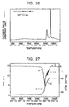
- Fig. 16 illustrates a DSC (a curve based on measurement by a differential scanning calorimeter) for a raw material powder obtained by pulverizing a quenched non-crystalline alloy thin strip having a composition Fe 73 Al 5 Ga 2 P 11 C 5 B 4 ; and Fig. 17 illustrates a DSC curve for a sinter obtained by spark-plasma-sintering the aforesaid powder at a sintering temperature of 430°C.
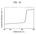
- Fig. 18 illustrates a TMA (thermomechanical analysis curve) for a quenched non-crystalline alloy thin strip before pulverization.
- Tx 512°C
- Tg 465°C
- Tx 512°C
- Tg 465°C
- Tx, Tg and ⁇ Tx are the same between the non-crystalline alloy pulverized powder and the sinter.
- the TMA (thermomechanical analysis) curve shown in Fig. 18 reveals that the sample is sharply elongated with the increase in temperature within a temperature region of from 440 to 480°C. This suggests that softening of the alloy occurs in the supercooled liquid temperature region. Solidification and forming by the utilization of this softening phenomenon of the non-crystalline alloy are favorable for increasing density.
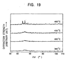
- Fig. 19 illustrates the results of an X-ray diffraction analysis of a sinter in an as-sintered state when the raw material powder is spark-plasma-sintered at sintering temperatures 380°C, 400°C, 430°C and 460°C, respectively.
- the results demonstrate harrowed patterns, suggesting the presence of an amorphous single phase structure.
- the diffraction curve shows sharp peaks suggesting the presence of a crystalline phase.
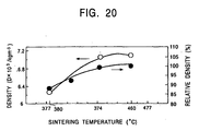
- Fig. 20 illustrates the sintering temperatures in cases of sintering by the spark plasma sintering process, and the resultant densities of the sinters.
- density of the sinter increases with the increase in the sintering temperature, and a sinter having a high density as represented by a relative density of at least 99.7% is obtained by sintering at a sintering temperature of at least 430°C.
- a sinter having a high density as represented by a relative density of at least 99.7% is obtained by sintering at a sintering temperature of at least 430°C.
- Vichers hardness was measured: a result of 1,250 Hv was shown, suggesting the possibility to provide a very hard product. Sintering in this case was accomplished by heating the powder under a pressure of 6.5 tons/cm 2 from the room temperature to the sintering temperature of 430°C at a heating rate of 100°C/min.
- a glassy alloy thin strip sample manufactured in the same manner as in the above-mentioned Examples 1 to 3 was pulverized in the open air by means of a rotor mill into powder. From among the resultant powder particles, those having particle szes within a range of from 53 to 105 ⁇ m were selected and used as a raw material powder for the subsequent steps.
- the above-mentioned powder in an amount of about 2 g was charged into a die made of WC (tungsten carbide) by the use of a hand press, and then charged into a forming mold 41 shown in Fig. 2.
- the interior of the chamber was pressed by the upper and the lower punches 42 and 43 in an atmosphere of 3 x 10 -5 torr, and a bulk-shaped sinter was obtained by sintering the raw material powder by feeding pulse waves from the energizing unit.
- the pulse waveform comprised a stoppage for two pulses after flow of 12 pulses as shown in Fig. 4, and the raw material powder was heated with current of up to 4,700 to 4,800 A.
- Sintering in this case was accomplished by heating the raw material powder under a pressure of 6.5 tons/cm 2 from the room temperature to the sintering temperature, and then holding for five minutes.
- the heating rate in sintering was 100°C/minute.
- the glass transition temperature (Tg), crystallization temperature (Tx), temperature range ( ⁇ Tx) of the supercooled liquid region, Vickers hardness (Hv) and compression strength ( ⁇ c, f) were measured for the resultant bulk-shaped sinter.
- Vickers hardness was measured, for a glassy alloy of each composition, by preparing a pin-shaped sample having a diameter of from 1 to 10 mm and a length of from 50 to 100 mm, and applying a load of 500 g by means of a Vickers micro-hardness meter.
- the glassy alloy samples gave a Vickers hardness within a range of from 1,250 to 1,370, and a very large value of compression strength within a range of from 3,400 to 3,800 Mpa.
Landscapes
- Chemical & Material Sciences (AREA)
- Health & Medical Sciences (AREA)
- Physical Education & Sports Medicine (AREA)
- General Health & Medical Sciences (AREA)
- Engineering & Computer Science (AREA)
- Mechanical Engineering (AREA)
- Organic Chemistry (AREA)
- Metallurgy (AREA)
- Materials Engineering (AREA)
- Life Sciences & Earth Sciences (AREA)
- Wood Science & Technology (AREA)
- Powder Metallurgy (AREA)
- Golf Clubs (AREA)
- Continuous Casting (AREA)
Description
- The present invention relates to a method of producing a sintered bulk glassy alloy using spark plasma sintering.
- Some kinds of multi-element alloy have a property of not crystallizing when a composition is quenched from a molten state, and transferring to a vitreous solid via a supercooled liquid state having a certain temperature range. A non-crystalline alloy falling under this category is known as a glassy alloy. Conventionally known amorphous alloys include an Fe-P-C-system non-crystalline alloy manufactured for the first time in the 1960s, an (Fe, Co, Ni)-P-B-system and an (Fe, Co, Ni)-Si-B-system non-crystalline alloys manufactured in the 1970s, and an (Fe, Co, Ni)-M(Zr, Hf, Nb)- system non-crystalline alloy and an (Fe, Co, Ni)-M(Zr, Hf, Nb)-B-system non-crystalline alloy manufactured in the 1980s. These alloys, having magnetism, were expected to be applied as non-crystalline magnetic materials.
- Since any of the conventional amorphous alloys has a tight temperature range in the supercooled liquid state, a non-crystalline product cannot be formed unless it is quenched at a high cooling rate on a level of 105°C/s by the application of a method known as the single roll process. The product manufactured by quenching by the single roll process took a shape of a thin strip having a thickness of up to about 50 µm, and a bulk-shaped non-crystalline solid was unavailable. When a bulk-shaped formed product is to be obtained from this thin strip, a sinter is obtained by crushing the thin strip resulting from the application of the liquid quenching process, and sintering the crushed strip under pressure in a sealed space. The sinter produced from the conventional amorphous alloy is porous and brittle, and is not applicable as a part subjected to stress such as a gear, a milling head, a golf club head or a golf club shaft.
- Glassy alloys known as having a relatively wide temperature range in the supercooled liquid state, and giving a non-crystalline solid through slower cooling include Ln-Al-TM, Mg-Ln-TM, ZR-Ln-TM (where, Ln is a rare-earth element, and TM is a transition metal)-based alloys developed during the period of 1988 through 1991. Non-crystalline solids having a thickness of several mm available from these glassy alloys have special compositions in all cases and contain rare-earth elements, resulting in a high cost, and no sufficient study is made regarding applications.
- The head portion of a wood-type golf club is usually manufactured with a metal such as stainless steel, an aluminum alloy or a titanium alloy as a material, and the resultant metal wood forms the main current in the market. As compared with the conventional persimmon wood, the metal would provide an advantage of a very high degree of freedom in designing the head.
- In an iron-type golf club also iron (soft iron), stainless steel, carbon, titanium alloy and various other materials are used for the head.
- In a putter-type golf club as well, iron (soft iron), stainless steel, titanium alloy, duralumin and various other materials are applicable.
- For the shaft for a golf club, the carbon shaft excellent in lightness and easiness to handle forms the main current in place of the conventional steel shaft. The carbon shaft have advantage of a high degree of freedom in design, and various kinds of shaft are now commercially available, including those for frail women and for professional golfers.
- For a wood-type golf club having a head made of stainless steel, it is believed that only a head having a relatively large thickness and a small volume (up to about 220 cc) is manufacturable because of a strength not so-high of the material and a high specific gravity.
- An aluminum alloy used for a golf clubhead is generally believed manufacturable into a large head because of a high specific gravity, but inferior to a stainless steel or titanium alloy head in yardage.
- A titanium alloy, which is suitable as a material for a golf club because of a high strength and an excellent repellent force, must be fabricated in a vacuum or in an inert gas and the yield is low, resulting in a very high unit cost of a head.
- For the iron-type golf club, the head made of soft iron has defects of a relatively large specific gravity and easy susceptibility to flaws.
- A stainless steel head, which is excellent in durability, does not permit adjustment if the lie angle or the loft angle, and is kept at arm's length by senior golfers.
- A head made of a titanium alloy is defective in that fabrication requires much time and labor, leading to a very high unit cost as described above.
- As compared with the above-mentioned metal heads, a carbon head is far more susceptible to flaws and handling must be careful.
- A putter-type golf club should preferably be provided simultaneously with appropriate bounce and weight, but a material satisfying these requirements has not as yet been existent.
- A carbon shaft for a golf club has generally a configuration in which it comprises an inner layer obtained by aligning carbon fiber groups in a direction, impregnating the same with a thermosetting synthetic resin and forming the same into a tubular shape, and an outer layer available by aligning fine line or filament-shaped alloy groups in a direction, impregnating the same with a thermosetting synthetic resin, and forming the same. The alloy used for the outer layer has an important effect on properties of the carbon shaft. In order to manufacture a shaft light in weight, it is necessary to make the alloy of the outer layer finer, but this results in a lower strength. In order to increase strength, it suffices to use larger alloy lines, but this leads to a larger weight.
- EP-A-0747498 discloses a bulk ferrous metal glassy alloy.
- During search for a high-hardness material having excellent properties as parts having surface fine irregularities such as a gear, a milling head, a golf club head and a golf club shaft, the present inventors found that a certain glassy alloy had a relatively wide temperature range in the supercooled state, was capable of being manufactured into a bulk-shape non-crystalline solid product, and gave a very high-hardness non-crystalline solid product. Further, possibly was found to manufacture a high-hardness parts having fine surface irregularities by sintering powder of this glassy alloy at a sintering temperature near the crystallization temperature or casting the same in a mold, thus arriving at development of the present invention. The present invention was developed in a view of the above-mentioned circumstances, and has an object to provide a high-hardness sinter or casting having fine surface irregularities manufactured from a glassy alloy permitting formation of a high-hardness bulk-shaped non-crystalline form.
- The sinter of the present invention is produced according to the claim.
- According to the present invention there is provided a method of producing a sintered bulk glassy alloy, comprising spark plasma sintering a high-hardness glassy alloy at a temperature of at least 300°C, the alloy composition in atomic % being:
- Al : from 1 to 10%,
- Ga : from 0.5 to 4%,
- P : from 0 to 15%,
- C : from 2 to 7%,
- B : from 2 to 10%,
- Si : from 0 to 15%, and
- the balance Fe; and the alloy temperature interval ΔTx in the supercooled liquid region as expressed by ΔTx = Tx - Tg (where, Tx is a crystallization temperature and Tg is a glass transition temperature) is at least 20°C.
-
- The manufacturing method may preferrably comprise the steps of applying a heat treatment to the same so that at least a part thereof is crystallized.
- In the invention, a crystalline phase precipitated through a crystallization treatment shall also be called a glassy alloy. An alloy having ΔTx is called a glassy alloy and one not having ΔTx is called an amorphous for discrimination.
-
- Fig. 1 is a perspective view illustrating an embodiment of the gear of the present invention;
- Fig. 2 is a sectional view illustrating the structure of a main part of an embodiment of the spark plasma sintering machine for manufacturing the sinter of the invention;
- Fig. 3 is a perspective view illustrating a forming mold of the spark plasma sintering machine shown in Fig. 2;
- Fig. 4 is a diagram illustrating an example of pulse current waveform impressed on a raw material powder in the spark plasma sintering machine shown in Fig. 2;
- Fig. 5 is a front view illustrating the overall configuration of the example of the spark plasma sintering machine for manufacturing the sinter of the invention;
- Fig. 6 is a perspective view illustrating an embodiment of the gear cutter of the invention;
- Fig. 7 is a perspective view illustrating an embodiment of the side milling cutter of the invention;
- Fig. 8 is a perspective view illustrating a first embodiment of the golf clubhead which is an embodiment of the invention;
- Fig. 9 is an exploded view illustrating a second embodiment of the golf clubhead which is an embodiment of the invention;
- Fig. 10 is a front view illustrating a third embodiment of the golf clubhead which is an embodiment of the invention;
- Fig. 11 is an exploded view illustrating a fourth embodiment of the golf clubhead which is an embodiment of the invention;
- Fig. 12 is a partial sectional view illustrating of the golf club shaft which is an embodiment of the invention;
- Fig. 13 is a schematic view illustrating a typical casting machine used for manufacturing the casting;
- Fig. 14 is a schematic view illustrating a pattern of use of the casting machine shown in Fig. 13;
- Fig. 15 a schematic view illustrating another typical casting machine;
- Fig. 16 is a graph illustrating a DSC curve of a raw material powder in an example;
- Fig. 17 is a graph illustrating a DSC curve of a sinter in an example;
- Fig. 18 is a graph illustrating a TMA curve of a quenched non-crystalline alloy thin strip in an example;
- Fig. 19 is a graph illustrating an X-ray diffraction figure of a sinter obtained by sintering at a temperature of 380 to 460°C in an example;
- Fig. 20 is a graph illustrating sintering temperature dependency of sinter density obtained in an example;
- Fig. 26 is a graph illustrating a DSC curve of a glassy alloy thin strip sample of a composition Fe63Co7Nb5Zr4B20; and
- Fig. 27 is a graph illustrating a TMA curve and a DTMA curve of a glassy alloy thin strip sample of a composition Fe63Co7Nb6Zr4B20.
-
- Embodiments of the invention and other examples of alloys and related products will now be described.
- First, the glassy alloy used in the invention will be described.
- A glassy alloy having a temperature interval ΔTx of the supercooled liquid as expressed by the formula ΔTx = Tx - Tg (where, Tx is a crystallization temperature, and Tg is the glass transition temperature) is employed in the invention. Applicable glassy alloys include metal-metalloid glassy alloys and metal-metal glassy alloys, as given in the claim.
- The above-mentioned metal-metalloid glassy alloy has a temperature interval ΔTx of the supercooled liquid of at least 35°C, or in some compositions, a remarkable temperature interval of 40 to 50°C. This has never been foreseen from the Fe-based alloys known from the conventional findings. In addition, while a non-crystalline alloy has so far been achieved only in the form of a thin strip, the present invention gives a bulk-shaped one which is far more excellent in practical merits.
- The metal-metalloid glassy alloy used in the invention is given in the claim.
- By further adding Si, it is possible to improve the temperature interval ΔTx of the supercooled liquid and increase the critical thickness of becoming an amorphous single phase. As a result, it is possible to increase thickness of the metal-metalloid glassy alloy. The Si content should preferably be up to 15% since a higher Si content causes disappearance of ΔTx in the supercooled liquid region.
- The composition of the metal-metalloid glassy alloy claimed comprises, in atomic %, from 1 to 10% Al, 0.5 to 4% Ga, from 0 to 15% P, from 2 to 7% C, from 2 to 10% B, from 0 to 15% Si and the balance Fe, and may contain incidental impurities.
- Further, in order to obtain a larger ΔTx in the supercooled liquid region, the composition should preferably include from 6 to 15% P and from 2 to 7% C, and this gives a value of ΔTx in the supercooled liquid region of at least 35°C.
- With any of these compositions, there is available a value of temperature interval ΔTx of the supercooled liquid of at least 35°C, or in certain Compositions, at least 40 to 50°C.
- Fig. 1 is a perspective view illustrating a gear manufactured by a manufacturing method of a part having fine surface irregularities.
- The
gear 1 is manufactured by sintering the powder of the above-mentioned glassy alloy. Thegear 1 has teeth (fine irregularities) 2 on the outer periphery thereof. - Examples of manufacture of the
gear 1 will now be described in detail. - Fig. 2 illustrates main portions of a typical spark plasma sintering machine suitably used for manufacturing the
gear 1. The spark plasma sintering machine of this example mainly comprises a cylindrical formingmold 41, anupper punch 42 and alower punch 43 for pressing a raw material powder (powder particles) charged in this formingmold 41, apunch electrode 44 supporting thelower punch 43 and serving as an electrode on one side when feeding pulse current as described later, anotherpunch electrode 45 pressing down theupper punch 42 and serving as another electrode for feeding pulse current, and athermocouple 47 for measuring temperature of the powder raw material held between the upper and thelower punches Fine surface irregularities 41a are formed on the inner surface of the formingmold 41 as shown in Fig. 3 in response to the shape of a target form (shape of a gear in this embodiment). A cavity formed by the upper and thelower punches mold 41 in the interior of this spark plasma sintering machine has a shape substantially in agreement with the shape of the target formed product (shape of thegear 1 in this embodiment). In Fig. 2,reference numeral 41b represents a core rod. - Fig. 5 illustrates an overall configuration of the above-mentioned spark plasma sintering machine. The spark plasma sintering machine A is a kind of spark plasma sintering machine called Model SPS-2050 manufactured by Sumitomo Cool Mining Co., Ltd., and has the main portions of which the structure is shown in Fig. 2.
- The machine shown in Fig. 5 has an
upper base 51 and alower base 52, achamber 53 provided in contact with theupper base 51, and most of the structure shown in Fig. 2 are housed in thischamber 53. Thechamber 53 is connected to a vacuum evacuation unit and an atmospheric gas feeding unit not shown, and a raw metal powder (powder particles) 46 to be charged between the upper and thelower punches lower punches punch electrodes punches punch electrodes - In order to manufacture a
gear 1 from a glassy alloy by means of the spark plasma sintering machine having the above-mentioned configuration, a raw material powder for forming 46 should be prepared. - A manufacturing process of the
raw material powder 46 comprises the step, for example, of preparing a single-element powder or single-element lumps for each of the components of the glassy alloy (may be partially alloyed in advance), mixing these single-element powder and single-element lumps, the melting the resultant mixed powder in an inert gas atmosphere such as Ar gas in a melting unit such as a crucible to obtain an alloy melt having a prescribed composition, forming a bulk-shaped, ribbon-shaped, linear or powdery shape by the casting, process of pouring the alloy melt into a mold and slowly cooling the same, by the quenching process of using a single roll or dual rolls, by the wet spinning process, by the solution extracting process, or by high-pressure gas spraying process, and the pulverizing the resultant product other than powder. - After preparation of the
raw material powder 46 as described above, the subsequent steps comprise charging the powder into a formingmold 41 provided between the upper and thelower punches chamber 53, conducting forming by applying a pressure from above and below with thepunches raw material powder 46 for heating and forming. In this spark plasma sintering, it is possible to heat theraw material powder 46 rapidly at a prescribed heating rate with the supplied current, and to strictly control temperature of theraw material powder 46 in response to the value of supplied current. It is therefore possible to perform temperature control far more accurately than in heating with a heater, thus permitting sintering under conditions close to ideal ones as preciously designed. - In the invention, a sintering temperature of at least 300°C is required for ensuring solidification and forming of the raw material powder. Since the glassy alloy used as the raw material powder has a large value of temperature interval ΔTx(Tx-Tg) of the supercooled liquid, a high-density sinter is suitably available by conducting sintering under pressure by the utilization of viscous flow generated at a temperature within a range of from Tg to Tx.
- Because of the special configuration of the spark plasma sintering machine, the monitored sintering temperature is the temperature of the thermocouple provided in the die, resulting in a temperature lower than that to which the powder sample is exposed.
- Particularly, when Si is added to a metal-metalloid glassy alloy, there occurs an increase in the crystallization temperature, leading to a larger temperature interval ΔTx of the supercooled liquid. A thermally more stable amorphous material is therefore available. It is therefore possible to obtain a bulk-shaped sinter having a higher density as compared with the case using a raw material powder not containing Si, by pulverizing the glassy alloy, and conducting sintering under pressure.
- In the invention, the heating rate for sintering should preferably be at least 10°/minute.
- The pressure in sintering should preferably be at least 3 tons/cm2 because a sinter cannot be formed under a lower pressure.
- A heat treatment for annealing or partial crystallization may be applied to the resultant sinter. The heat treatment temperature in this case, when heat-treating a metal-metalloid glassy alloy, should preferably be within a range of from 300 to 500°, or more preferably, from 300 to 450°C. When heat-treating a metal-metal glassy alloy, temperature should preferably within a range of from 427°C (700 K) to 627°C (900 K), or more preferably, from 477°C (750 K) to 523°C (800 K).
- Among the manufacturing conditions, a suitable cooling rate is determined, depending upon the alloy composition, means for manufacture thereof, the size of the product and the shape thereof.
- In the manufacturing method of a gear, a
gear 1 comprising a bulk-shaped sinter is available by filling a formingmold 41 havingfine irregularities 41a with the powder (raw material powder) 46 of the above-mentioned glassy alloy, and sintering thepowder 46 of the glassy alloy at a sintering temperature near the crystallization-temperature. The above-mentioned glassy alloy has a very broad temperature interval ΔTx of the supercooled liquid region, permits manufacture of a bulk-shaped sinter having a thickness sufficient to apply to a gear, and manufacture of a high-hardness sinter. Thegear 1 comprising the sinter obtained by the foregoing method has the same chemical composition as the glassy alloy used as the raw material powder, exhibits a high hardness, and can have a further improved hardness through a heat treatment. - It is therefore possible to obtain a gear of a very high performance by manufacturing the same in accordance with the above.
- Fig. 6 is a perspective view illustrating a gear cutter manufactured by the manufacturing method of a part having fine surface irregularities.
- This
gear cutter 3 is manufactured by sintering the powder of the above-mentioned glassy alloy. Thegear cutter 3 has a cutting edge (fine irregularities) on the outer periphery. - This
gear cutter 3 can be manufactured in the same manner as in the above-mentioned manufacturing method of a gear except for the use of a forming mold having fine irregularities formed on the inner surface in response to the shape of the gear cutter, of the spark plasma sintering machine. - The
gear cutter 3 thus obtained has the same composition as the glassy alloy used as the raw material powder, exhibits a high hardness, and can have a further improved hardness through a heat treatment. The cutting edge 4 of thegear cutter 3 should preferably be polished for finding. - Fig. 7 is a perspective view illustrating a side milling cutter manufactured by the manufacturing method of a part having fine irregularities.
- This
side milling cutter 5 is manufactured by sintering the powder of the above-mentioned glassy alloy. Theside milling cutter 5 has a cutting edge (fine irregularities) on the outer periphery. - The
side milling cutter 5 can be manufactured in the same manner as in the above-mentioned manufacturing method of a gear except for the use of a forming mold having fine irregularities formed on the inner surface in response to the shape of the side milling cutter, of the spark plasma sintering machine. - The
side milling cutter 5 thus obtained has the same composition as the glassy alloy used as the raw material powder, exhibits a high hardness, and can have a further improved hardness through a heat treatment. Thecutting edge 6 of theside milling cutter 5 should preferably be polished for finishing. - In the case of manufacturing the bulk-shaped sinter comprising the glassy alloy from the powder of the glassy alloy by the spark plasma sintering process has been described.
- Because the material exhibits a remarkable viscous flow within a range of from Tg to Tx, the product can be formed by clog-forging by the heating it to a temperature within a range of from Tg to Tx.
- Fig. 8 a perspective view illustrating a first golf club head. In this wood-type
golf club head 10, the entire head is composed of a high-hardness glassy alloy. This gives an improved bounce sufficient to ensure a longer yardage. Even when the sole portion rubs the ground upon swinging, the head is hardly damaged. Since even contact with other club or the like does not easily cause flaws, a good exterior view can be kept for a longer period of time. - The glassy alloy may be used only for a part of the golf clubhead. Fig. 9 is an exploded view illustrating a second golf clubhead. This has a configuration in which a
face portion 13 is fitted to, and fixed to, anopening 12 provided in the wood-type golf clubheadmain body 11. A golf clubhead of the invention is available by making this wood-type golf clubheadmain body 11 with a conventional material such as stainless steel, and making only theface portion 13 with a glassy alloy. - By adopting this configuration, it suffices to compose only the face portion with the glassy alloy. It is thus easier to fabricate the head and possible to provide the head at a lower cost.
- Fig. 10 is a perspective view illustrating a third golf clubhead. In this iron-
type golf clubhead 14, the entire head is made of the above-mentioned glassy alloy. In this iron-type golf clubhead 14, the entire head is composed of a high-hardness glassy alloy. This gives an improved bounce sufficient to ensure a longer yardage. Even when the sole portion rubs the ground upon swinging, the head is hardly damaged. Since even contact with the other club or the like does not easily cause flaws, a good exterior view can be kept for a longer period of time. - The glassy alloy may be used only for a part of the golf clubhead Fig. 11 is an exploded view illustrating a fourth golf clubhead has a configuration in which a
face portion 17 is fitted to, and fixed to, anopening 16 provided in the iron-type golf clubheadmain body 15. A golf clubhead is available by making this iron-type golf clubheadmain body 15 with a conventional material such as stainless steel, and making only theface portion 17 with a glassy alloy. - By adopting this configuration, it suffices to compose only the face portion with the glassy alloy. It is thus easier to fabricate the head and possible to provide the head at a lower cost.
- Fig. 12 is a partial sectional view illustrating a golf club shaft of the invention. This
golf club shaft 18 comprises aninner layer 19 formed into a tubular shape by impregnating carbon fiber groups aligned in a direction with a thermosetting synthetic resin, and anouter layer 20 formed by impregnating fine line or filament-shaped alloy groups aligned in a direction with a thermosetting synthetic resin. Shaft strength can be improved by composing the fine line or filament-shaped alloy groups with a high-hardness glassy alloy, and further, because strength is not improved by increasing fine line thickness, an increase in the shaft weight is inhibited. - In order to manufacture the golf clubhead it is necessary to manufacture a sheet-shaped glassy alloy. A method of manufacturing a sheet-shaped glassy alloy is the spark plasma sintering process described above.
- The glassy alloy used for the above-mentioned gear, gear cutter, golf clubhead, and golf club shaft can be used by sintering by the foregoing spark plasma sintering process, or in the form of a casting formed by the casting process by means of a casting mold. Such applications will now be described with reference to the drawings.
- An ingot having an atomic component ratio of Fe73A15Ga2P11 C5B4 was prepared by weighing Fe, Al and Ga, an Fe-C alloy, an Fe-P alloy and B as raw materials in prescribed amounts, respectively, and melting these raw , materials in an Ar atmosphere under a reduced pressure in a high frequency induction heater. The thus prepared ingot was melted in a crucible, and a quenched thin strip comprising an amorphous single-phase-structure having a thickness of from 35 to 135 µm was obtained in an Ar atmosphere under a reduced pressure by the single roll process of quenching the melt by spraying the same form a nozzle of the crucible onto a rotating roll. The thus obtained quenched thin strip was analyzed by differential scanning calorimeter (DSC) measurement: the result suggested that ΔTx was within a very broad range as at least 46.9°C.
- The quenched thin strip was pulverized by crushing the same in the open air by means of a rotor mill. Particles having particle sizes within a range of from 53 to 105 µm were selected for the resultant powder particles, and used as the raw material powder for subsequent steps.
- The above-mentioned raw material powder in an amount of about 2g was charged into a die made by WC by means of a hard press, and then charged into a forming
mold 41 shown in Fig. 2. The interior of the chamber was pressed with the upper and thelower punches - The pulse waveform comprised stoppage for two pulses after 12 pulses as shown in Fig. 4, and the raw material powder was heated with current of up to 4,700 to 4,800 A.
- Sintering was carried out by heating the sample from the room temperature to the sintering temperature under a pressure of 6.5 tons/cm2 applied on the sample, and holding for about five minutes. The heating rate was 100°C/min.
- Fig. 16 illustrates a DSC (a curve based on measurement by a differential scanning calorimeter) for a raw material powder obtained by pulverizing a quenched non-crystalline alloy thin strip having a composition Fe73Al5Ga2P11C5B4; and Fig. 17 illustrates a DSC curve for a sinter obtained by spark-plasma-sintering the aforesaid powder at a sintering temperature of 430°C.
- Fig. 18 illustrates a TMA (thermomechanical analysis curve) for a quenched non-crystalline alloy thin strip before pulverization.
- From the DSC curve shown in Fig. 16, Tx = 512°C, Tg = 465°C and ΔTx = 47°C for the raw material powder are derived. A supercooled liquid region is existent over a wide temperature region of up to the crystallization temperature, with a large value of ΔTx = Tx - Tg, thus suggesting a high amorphous phase forming ability of the alloy of this composition.
- From the DSC curve shown in Fig. 17, Tx = 512°C, Tg = 465°C and ΔTx = 47°C for the sinter are determined. The results shown in Figs. 16 and 17, Tx, Tg and ΔTx are the same between the non-crystalline alloy pulverized powder and the sinter.
- Further, the TMA (thermomechanical analysis) curve shown in Fig. 18 reveals that the sample is sharply elongated with the increase in temperature within a temperature region of from 440 to 480°C. This suggests that softening of the alloy occurs in the supercooled liquid temperature region. Solidification and forming by the utilization of this softening phenomenon of the non-crystalline alloy are favorable for increasing density.
- Fig. 19 illustrates the results of an X-ray diffraction analysis of a sinter in an as-sintered state when the raw material powder is spark-plasma-sintered at sintering
temperatures 380°C, 400°C, 430°C and 460°C, respectively. In the samples sintered at 380°C, 400°C and 430°C, the results demonstrate harrowed patterns, suggesting the presence of an amorphous single phase structure. In the sample sintered at 460°C, on the other hand, the diffraction curve shows sharp peaks suggesting the presence of a crystalline phase. - Fig. 20 illustrates the sintering temperatures in cases of sintering by the spark plasma sintering process, and the resultant densities of the sinters.
- As shown in Fig. 20, density of the sinter increases with the increase in the sintering temperature, and a sinter having a high density as represented by a relative density of at least 99.7% is obtained by sintering at a sintering temperature of at least 430°C. By increasing the pressure during sintering, it is possible to obtain a high density sinter even at a lower temperature.
- These results suggest that, when preparing a formed product by the use of a glassy alloy having a composition Fe73Al5Ga2P11C5B4, it is possible to obtain a product having an amorphous single-phase structure in as-sintered state with a high density by selecting a sintering temperature of up to 430°C (in other words, when the crystallization temperature is Tx and the sintering temperature is T1, within a range T1 ≤ Tx).
- For a sinter sample resulting from sintering of a glassy alloy powder having a composition Fe73Al5Ga2P11C5B4 by the spark plasma sintering process, Vichers hardness was measured: a result of 1,250 Hv was shown, suggesting the possibility to provide a very hard product. Sintering in this case was accomplished by heating the powder under a pressure of 6.5 tons/cm2 from the room temperature to the sintering temperature of 430°C at a heating rate of 100°C/min.
- A glassy alloy thin strip sample manufactured in the same manner as in the above-mentioned Examples 1 to 3 was pulverized in the open air by means of a rotor mill into powder. From among the resultant powder particles, those having particle szes within a range of from 53 to 105 µm were selected and used as a raw material powder for the subsequent steps.
- The above-mentioned powder in an amount of about 2 g was charged into a die made of WC (tungsten carbide) by the use of a hand press, and then charged into a forming
mold 41 shown in Fig. 2. the interior of the chamber was pressed by the upper and thelower punches - The glass transition temperature (Tg), crystallization temperature (Tx), temperature range (ΔTx) of the supercooled liquid region, Vickers hardness (Hv) and compression strength (σc, f) were measured for the resultant bulk-shaped sinter. Vickers hardness was measured, for a glassy alloy of each composition, by preparing a pin-shaped sample having a diameter of from 1 to 10 mm and a length of from 50 to 100 mm, and applying a load of 500 g by means of a Vickers micro-hardness meter. Compression strength was measured, for a glassy alloy of each composition, by preparing a sample having a diameter of 2.5 mm and a length of 60 mm, and using a compression strength meter (Model 4204 made by Instron Co., Ltd.). The results are shown in Table 1.
Alloy Composition Tg °C Tx °C ΔTx °C Hv σc, f MPa Fe72Al5Ga2P10C6B4Si1 490 541 51 1250 - - As is clear from the results shown in Table 1, the glassy alloy samples gave a Vickers hardness within a range of from 1,250 to 1,370, and a very large value of compression strength within a range of from 3,400 to 3,800 Mpa.
Claims (1)
- A method of producing a sintered bulk glassy alloy, comprising spark plasma sintering a high-hardness glassy alloy at a temperature of at least 300°C, the alloy composition in atomic % being:and wherein the alloy temperature interval ATx in the supercooled liquid region as expressed by ΔTx = Tx - Tg (where, Tx is a crystallization temperature and Tg is a glass transition temperature) is at least 20°C.Al : from 1 to 10%,Ga : from 0.5 to 4%,P : from 0 to 15%,C : from 2 to 7%,B : from 2 to 10%,Si : from 0 to 15%, andthe balance Fe;
Applications Claiming Priority (6)
| Application Number | Priority Date | Filing Date | Title |
|---|---|---|---|
| JP23306997 | 1997-08-28 | ||
| JP9233069A JPH1157080A (en) | 1997-08-28 | 1997-08-28 | Golf club head and shaft for golf club |
| JP233069/97 | 1997-08-28 | ||
| JP24993297A JPH1171602A (en) | 1997-08-29 | 1997-08-29 | Manufacture of parts having fine rugged part |
| JP24993297 | 1997-08-29 | ||
| JP249932/97 | 1997-08-29 |
Publications (3)
| Publication Number | Publication Date |
|---|---|
| EP0899353A2 EP0899353A2 (en) | 1999-03-03 |
| EP0899353A3 EP0899353A3 (en) | 1999-05-19 |
| EP0899353B1 true EP0899353B1 (en) | 2004-05-12 |
Family
ID=26530819
Family Applications (1)
| Application Number | Title | Priority Date | Filing Date |
|---|---|---|---|
| EP98306496A Expired - Lifetime EP0899353B1 (en) | 1997-08-28 | 1998-08-14 | Method of sintering an iron-based high-hardness glassy alloy |
Country Status (5)
| Country | Link |
|---|---|
| US (4) | US6086651A (en) |
| EP (1) | EP0899353B1 (en) |
| KR (1) | KR19990023946A (en) |
| DE (1) | DE69823756T2 (en) |
| TW (1) | TW422887B (en) |
Families Citing this family (33)
| Publication number | Priority date | Publication date | Assignee | Title |
|---|---|---|---|---|
| EP0899353B1 (en) * | 1997-08-28 | 2004-05-12 | Alps Electric Co., Ltd. | Method of sintering an iron-based high-hardness glassy alloy |
| US6594157B2 (en) * | 2000-03-21 | 2003-07-15 | Alps Electric Co., Ltd. | Low-loss magnetic powder core, and switching power supply, active filter, filter, and amplifying device using the same |
| US6475427B1 (en) * | 2000-05-31 | 2002-11-05 | Callaway Golf Company | Golf club with multiple material weighting member |
| US6508978B1 (en) * | 2000-05-31 | 2003-01-21 | Callaway, Golf Company | Golf club head with weighting member and method of manufacturing the same |
| JP3546002B2 (en) * | 2000-08-29 | 2004-07-21 | 株式会社日立ユニシアオートモティブ | Manufacturing method of valve timing control device |
| JP4170753B2 (en) * | 2000-10-17 | 2008-10-22 | ファルマシア・アンド・アップジョン・カンパニー・エルエルシー | Method for producing oxazolidinone compound |
| US6689234B2 (en) | 2000-11-09 | 2004-02-10 | Bechtel Bwxt Idaho, Llc | Method of producing metallic materials |
| JP4452008B2 (en) * | 2000-12-08 | 2010-04-21 | 住友金属工業株式会社 | Method of manufacturing curved metal plate and golf club head |
| FR2826285B1 (en) * | 2001-06-25 | 2003-08-22 | Roger Cleveland Golf Co Inc | GOLF CLUB HEAD |
| JP3560591B2 (en) * | 2002-04-10 | 2004-09-02 | 独立行政法人 科学技術振興機構 | Soft magnetic Co-based metallic glass alloy |
| JP3913167B2 (en) * | 2002-12-25 | 2007-05-09 | 独立行政法人科学技術振興機構 | Bulk Fe-based sintered alloy soft magnetic material made of metallic glass and manufacturing method thereof |
| USRE47863E1 (en) * | 2003-06-02 | 2020-02-18 | University Of Virginia Patent Foundation | Non-ferromagnetic amorphous steel alloys containing large-atom metals |
| US7052561B2 (en) * | 2003-08-12 | 2006-05-30 | Ut-Battelle, Llc | Bulk amorphous steels based on Fe alloys |
| CN101709773B (en) * | 2003-09-02 | 2012-07-18 | 并木精密宝石株式会社 | Precision gear and production method of precision gear |
| KR100933849B1 (en) * | 2004-09-27 | 2009-12-24 | 더 리젠츠 오브 더 유니버시티 오브 캘리포니아 | Composite material and its manufacturing method |
| KR100701027B1 (en) * | 2005-04-19 | 2007-03-29 | 연세대학교 산학협력단 | Monolithic Metallic Glasses With Enhanced Ductility |
| US7892210B2 (en) * | 2005-10-03 | 2011-02-22 | Baxa Corporation | Apparatus, method and system for administration of IV liquid medication and IV flush solutions |
| TWI337203B (en) | 2005-12-30 | 2011-02-11 | Ind Tech Res Inst | Multi metal base thermal resistance alloy and a mold with the multi metal base thermal resistance alloy layer |
| US20080188321A1 (en) * | 2007-02-01 | 2008-08-07 | Feighery John J | Golf putter heads and methods of making them |
| WO2009062196A2 (en) | 2007-11-09 | 2009-05-14 | The Regents Of The University Of California | Amorphous alloy materials |
| WO2009069716A1 (en) * | 2007-11-27 | 2009-06-04 | Tohoku University | Production method of internal gear and internal gear made of metallic glass |
| KR101376074B1 (en) | 2011-12-06 | 2014-03-21 | 한국생산기술연구원 | Polycrystalline alloy having glass forming ability, method of fabricating the same, alloy target for sputtering and method of fabricating the same |
| KR102110462B1 (en) * | 2013-01-28 | 2020-05-14 | 한국생산기술연구원 | Method for corrosion resistance alloy thin film with amorphous phase |
| KR101452879B1 (en) * | 2013-03-29 | 2014-10-23 | 한국생산기술연구원 | Polycrystalline alloy having glass forming ability, method of fabricating the same, alloy target for sputtering and method of fabricating the same |
| KR101501067B1 (en) * | 2013-06-07 | 2015-03-17 | 한국생산기술연구원 | Polycrystalline alloy having glass forming ability, method of fabricating the same, alloy target for sputtering and method of fabricating the same |
| US9790580B1 (en) | 2013-11-18 | 2017-10-17 | Materion Corporation | Methods for making bulk metallic glasses containing metalloids |
| US9970079B2 (en) * | 2014-04-18 | 2018-05-15 | Apple Inc. | Methods for constructing parts using metallic glass alloys, and metallic glass alloy materials for use therewith |
| US10056541B2 (en) | 2014-04-30 | 2018-08-21 | Apple Inc. | Metallic glass meshes, actuators, sensors, and methods for constructing the same |
| US10161025B2 (en) | 2014-04-30 | 2018-12-25 | Apple Inc. | Methods for constructing parts with improved properties using metallic glass alloys |
| US9849504B2 (en) | 2014-04-30 | 2017-12-26 | Apple Inc. | Metallic glass parts including core and shell |
| US10000837B2 (en) | 2014-07-28 | 2018-06-19 | Apple Inc. | Methods and apparatus for forming bulk metallic glass parts using an amorphous coated mold to reduce crystallization |
| WO2018035458A1 (en) * | 2016-08-18 | 2018-02-22 | Karsten Manufacturing Corporation | Localized heat treatment |
| CN114987003B (en) * | 2022-06-24 | 2023-09-08 | 武汉苏泊尔炊具有限公司 | Method for manufacturing cutter and cutter |
Family Cites Families (13)
| Publication number | Priority date | Publication date | Assignee | Title |
|---|---|---|---|---|
| US3856513A (en) * | 1972-12-26 | 1974-12-24 | Allied Chem | Novel amorphous metals and amorphous metal articles |
| US4144058A (en) * | 1974-09-12 | 1979-03-13 | Allied Chemical Corporation | Amorphous metal alloys composed of iron, nickel, phosphorus, boron and, optionally carbon |
| US4221592A (en) * | 1977-09-02 | 1980-09-09 | Allied Chemical Corporation | Glassy alloys which include iron group elements and boron |
| JPS5675542A (en) * | 1979-11-20 | 1981-06-22 | Tdk Corp | Amorphous magnetic alloy material |
| JPS57202709A (en) * | 1981-06-08 | 1982-12-11 | Hitachi Metals Ltd | Magnetic material and manufacture therefor |
| US4529458A (en) * | 1982-07-19 | 1985-07-16 | Allied Corporation | Compacted amorphous ribbon |
| US4613371A (en) * | 1983-01-24 | 1986-09-23 | Gte Products Corporation | Method for making ultrafine metal powder |
| US4594104A (en) * | 1985-04-26 | 1986-06-10 | Allied Corporation | Consolidated articles produced from heat treated amorphous bulk parts |
| US5261664A (en) * | 1989-06-12 | 1993-11-16 | Donald Anderson | Golf club head and method of forming same |
| KR950014314B1 (en) * | 1990-11-30 | 1995-11-24 | 미쓰이세끼유 가가꾸고오교오 가부시끼가이샤 | Iron-base soft magnetic alloy |
| JP3904250B2 (en) * | 1995-06-02 | 2007-04-11 | 独立行政法人科学技術振興機構 | Fe-based metallic glass alloy |
| JPH09256122A (en) | 1996-03-19 | 1997-09-30 | Unitika Ltd | Ferrous amorphous alloy |
| EP0899353B1 (en) | 1997-08-28 | 2004-05-12 | Alps Electric Co., Ltd. | Method of sintering an iron-based high-hardness glassy alloy |
-
1998
- 1998-08-14 EP EP98306496A patent/EP0899353B1/en not_active Expired - Lifetime
- 1998-08-14 DE DE69823756T patent/DE69823756T2/en not_active Expired - Fee Related
- 1998-08-26 TW TW087114081A patent/TW422887B/en not_active IP Right Cessation
- 1998-08-26 US US09/140,806 patent/US6086651A/en not_active Expired - Lifetime
- 1998-08-27 KR KR1019980034931A patent/KR19990023946A/en not_active Application Discontinuation
-
1999
- 1999-09-29 US US09/407,411 patent/US6296681B1/en not_active Expired - Fee Related
- 1999-09-29 US US09/408,765 patent/US6287514B1/en not_active Expired - Lifetime
- 1999-09-29 US US09/408,900 patent/US6227985B1/en not_active Expired - Lifetime
Also Published As
| Publication number | Publication date |
|---|---|
| US6296681B1 (en) | 2001-10-02 |
| DE69823756D1 (en) | 2004-06-17 |
| TW422887B (en) | 2001-02-21 |
| US6086651A (en) | 2000-07-11 |
| US6227985B1 (en) | 2001-05-08 |
| KR19990023946A (en) | 1999-03-25 |
| EP0899353A3 (en) | 1999-05-19 |
| EP0899353A2 (en) | 1999-03-03 |
| US6287514B1 (en) | 2001-09-11 |
| DE69823756T2 (en) | 2005-04-14 |
Similar Documents
| Publication | Publication Date | Title |
|---|---|---|
| EP0899353B1 (en) | Method of sintering an iron-based high-hardness glassy alloy | |
| US6284061B1 (en) | Soft magnetic amorphous alloy and high hardness amorphous alloy and high hardness tool using the same | |
| US7622011B2 (en) | Spherical particles of Fe base metallic glass alloy, Fe base sintered alloy soft magnetic material in bulk form produced by sintering the same, and method for their production | |
| EP1880782B1 (en) | A method for evaluating a raw alloy for a magnet | |
| EP1045402B1 (en) | Soft magnetic alloy strip, manufacturing method and use thereof | |
| US7311874B2 (en) | Sputter target and method for fabricating sputter target including a plurality of materials | |
| CA2020338C (en) | Amorphous alloys superior in mechanical strength, corrosion resistance and formability | |
| EP0215168B2 (en) | Method for making rare-earth element containing permanent magnets | |
| US20070189916A1 (en) | Sputtering targets and methods for fabricating sputtering targets having multiple materials | |
| CN106415720B (en) | Magnetic recording non-retentive alloy and sputtering target material and magnetic recording media | |
| JP2008078496A (en) | OXIDE CONTAINING Co-BASED ALLOY MAGNETIC FILM, OXIDE CONTAINING Co-BASED ALLOY TARGET, AND MANUFACTURING METHOD THEREOF | |
| US6312530B1 (en) | Magnetostrictive material | |
| EP0092091B2 (en) | Apparatus for the production of magnetic powder | |
| JP2006509908A (en) | Composite metal products and methods of manufacturing such products | |
| JP2731454B2 (en) | Force sensor | |
| JPH1171602A (en) | Manufacture of parts having fine rugged part | |
| Ray | Bulk microcrystalline alloys from metallic glasses | |
| JP2812573B2 (en) | Magnetic head | |
| JPH08337839A (en) | Soft magnetic alloy compacted body and its production | |
| JP2740692B2 (en) | Mold | |
| JPH1092619A (en) | Fe-based soft magnetic metallic glass sintered body and its manufacture | |
| JPS62214602A (en) | Manufacture of green compact permanent magnet | |
| JPH1157080A (en) | Golf club head and shaft for golf club | |
| JPH04276070A (en) | Target for magnetron sputtering | |
| JPH02250964A (en) | Sendust alloy target and production thereof |
Legal Events
| Date | Code | Title | Description |
|---|---|---|---|
| PUAI | Public reference made under article 153(3) epc to a published international application that has entered the european phase |
Free format text: ORIGINAL CODE: 0009012 |
|
| AK | Designated contracting states |
Kind code of ref document: A2 Designated state(s): DE FR GB |
|
| AX | Request for extension of the european patent |
Free format text: AL;LT;LV;MK;RO;SI |
|
| PUAL | Search report despatched |
Free format text: ORIGINAL CODE: 0009013 |
|
| AK | Designated contracting states |
Kind code of ref document: A3 Designated state(s): AT BE CH CY DE DK ES FI FR GB GR IE IT LI LU MC NL PT SE |
|
| AX | Request for extension of the european patent |
Free format text: AL;LT;LV;MK;RO;SI |
|
| 17P | Request for examination filed |
Effective date: 19990619 |
|
| AKX | Designation fees paid |
Free format text: DE FR GB |
|
| 17Q | First examination report despatched |
Effective date: 20010322 |
|
| RTI1 | Title (correction) |
Free format text: METHOD OF SINTERING AN IRON-BASED HIGH-HARDNESS GLASSY ALLOY |
|
| GRAP | Despatch of communication of intention to grant a patent |
Free format text: ORIGINAL CODE: EPIDOSNIGR1 |
|
| GRAS | Grant fee paid |
Free format text: ORIGINAL CODE: EPIDOSNIGR3 |
|
| GRAA | (expected) grant |
Free format text: ORIGINAL CODE: 0009210 |
|
| RIN1 | Information on inventor provided before grant (corrected) |
Inventor name: INOUE, AKIHISA Inventor name: MAKINO, AKIHIRO Inventor name: MIZUSHIMA, TAKAO |
|
| AK | Designated contracting states |
Kind code of ref document: B1 Designated state(s): DE FR GB |
|
| REG | Reference to a national code |
Ref country code: GB Ref legal event code: FG4D |
|
| REF | Corresponds to: |
Ref document number: 69823756 Country of ref document: DE Date of ref document: 20040617 Kind code of ref document: P |
|
| PGFP | Annual fee paid to national office [announced via postgrant information from national office to epo] |
Ref country code: GB Payment date: 20040702 Year of fee payment: 7 |
|
| PGFP | Annual fee paid to national office [announced via postgrant information from national office to epo] |
Ref country code: FR Payment date: 20040727 Year of fee payment: 7 |
|
| ET | Fr: translation filed | ||
| PLBE | No opposition filed within time limit |
Free format text: ORIGINAL CODE: 0009261 |
|
| STAA | Information on the status of an ep patent application or granted ep patent |
Free format text: STATUS: NO OPPOSITION FILED WITHIN TIME LIMIT |
|
| 26N | No opposition filed |
Effective date: 20050215 |
|
| PG25 | Lapsed in a contracting state [announced via postgrant information from national office to epo] |
Ref country code: GB Free format text: LAPSE BECAUSE OF NON-PAYMENT OF DUE FEES Effective date: 20050814 |
|
| PGFP | Annual fee paid to national office [announced via postgrant information from national office to epo] |
Ref country code: DE Payment date: 20051025 Year of fee payment: 8 |
|
| GBPC | Gb: european patent ceased through non-payment of renewal fee |
Effective date: 20050814 |
|
| PG25 | Lapsed in a contracting state [announced via postgrant information from national office to epo] |
Ref country code: DE Free format text: LAPSE BECAUSE OF NON-PAYMENT OF DUE FEES Effective date: 20070301 |
|
| PG25 | Lapsed in a contracting state [announced via postgrant information from national office to epo] |
Ref country code: FR Free format text: LAPSE BECAUSE OF NON-PAYMENT OF DUE FEES Effective date: 20050831 |
|
| REG | Reference to a national code |
Ref country code: FR Ref legal event code: ST Effective date: 20111125 |