EP0898359A2 - Inverter - Google Patents
Inverter Download PDFInfo
- Publication number
- EP0898359A2 EP0898359A2 EP98810736A EP98810736A EP0898359A2 EP 0898359 A2 EP0898359 A2 EP 0898359A2 EP 98810736 A EP98810736 A EP 98810736A EP 98810736 A EP98810736 A EP 98810736A EP 0898359 A2 EP0898359 A2 EP 0898359A2
- Authority
- EP
- European Patent Office
- Prior art keywords
- inverter
- output
- secondary windings
- transformer
- series connection
- Prior art date
- Legal status (The legal status is an assumption and is not a legal conclusion. Google has not performed a legal analysis and makes no representation as to the accuracy of the status listed.)
- Withdrawn
Links
Images


Classifications
-
- H—ELECTRICITY
- H02—GENERATION; CONVERSION OR DISTRIBUTION OF ELECTRIC POWER
- H02M—APPARATUS FOR CONVERSION BETWEEN AC AND AC, BETWEEN AC AND DC, OR BETWEEN DC AND DC, AND FOR USE WITH MAINS OR SIMILAR POWER SUPPLY SYSTEMS; CONVERSION OF DC OR AC INPUT POWER INTO SURGE OUTPUT POWER; CONTROL OR REGULATION THEREOF
- H02M7/00—Conversion of ac power input into dc power output; Conversion of dc power input into ac power output
- H02M7/42—Conversion of dc power input into ac power output without possibility of reversal
- H02M7/44—Conversion of dc power input into ac power output without possibility of reversal by static converters
- H02M7/48—Conversion of dc power input into ac power output without possibility of reversal by static converters using discharge tubes with control electrode or semiconductor devices with control electrode
- H02M7/483—Converters with outputs that each can have more than two voltages levels
- H02M7/49—Combination of the output voltage waveforms of a plurality of converters
-
- H—ELECTRICITY
- H02—GENERATION; CONVERSION OR DISTRIBUTION OF ELECTRIC POWER
- H02M—APPARATUS FOR CONVERSION BETWEEN AC AND AC, BETWEEN AC AND DC, OR BETWEEN DC AND DC, AND FOR USE WITH MAINS OR SIMILAR POWER SUPPLY SYSTEMS; CONVERSION OF DC OR AC INPUT POWER INTO SURGE OUTPUT POWER; CONTROL OR REGULATION THEREOF
- H02M7/00—Conversion of ac power input into dc power output; Conversion of dc power input into ac power output
- H02M7/42—Conversion of dc power input into ac power output without possibility of reversal
- H02M7/44—Conversion of dc power input into ac power output without possibility of reversal by static converters
- H02M7/48—Conversion of dc power input into ac power output without possibility of reversal by static converters using discharge tubes with control electrode or semiconductor devices with control electrode
- H02M7/505—Conversion of dc power input into ac power output without possibility of reversal by static converters using discharge tubes with control electrode or semiconductor devices with control electrode using devices of a thyratron or thyristor type requiring extinguishing means
- H02M7/515—Conversion of dc power input into ac power output without possibility of reversal by static converters using discharge tubes with control electrode or semiconductor devices with control electrode using devices of a thyratron or thyristor type requiring extinguishing means using semiconductor devices only
- H02M7/521—Conversion of dc power input into ac power output without possibility of reversal by static converters using discharge tubes with control electrode or semiconductor devices with control electrode using devices of a thyratron or thyristor type requiring extinguishing means using semiconductor devices only in a bridge configuration
-
- H—ELECTRICITY
- H02—GENERATION; CONVERSION OR DISTRIBUTION OF ELECTRIC POWER
- H02M—APPARATUS FOR CONVERSION BETWEEN AC AND AC, BETWEEN AC AND DC, OR BETWEEN DC AND DC, AND FOR USE WITH MAINS OR SIMILAR POWER SUPPLY SYSTEMS; CONVERSION OF DC OR AC INPUT POWER INTO SURGE OUTPUT POWER; CONTROL OR REGULATION THEREOF
- H02M7/00—Conversion of ac power input into dc power output; Conversion of dc power input into ac power output
- H02M7/42—Conversion of dc power input into ac power output without possibility of reversal
- H02M7/44—Conversion of dc power input into ac power output without possibility of reversal by static converters
- H02M7/48—Conversion of dc power input into ac power output without possibility of reversal by static converters using discharge tubes with control electrode or semiconductor devices with control electrode
Definitions
- the present invention relates to the field of Power electronics. It relates to an inverter, comprehensively a plurality of from the same DC voltage source parallel working inverter bridges, their Output voltages are summed up via a transformer, which corresponds to the number of inverter bridges Number of primary windings and associated secondary windings each inverter bridge each connected to a primary winding on the output side and the secondary windings for the summation of the output voltages are connected in series, and the inverter bridges in accordance with an auxiliary control voltage pulse duration modulated and the auxiliary control voltages of the individual inverter bridges with each other have a constant phase difference, and wherein the Transformer has a center tap, which has a Earth connection is earthed.
- traction current converter 10 for example a (thyristor-equipped) Power converter 13
- the three-phase current via a transformer 12 decreases from the three-phase network 11 and into a direct current converts a DC link 14 to Smoothing or temporary storage, and an inverter 15, which turns the direct current back into an alternating current of the desired Frequency converted and fed into the rail network 16.
- inverter 15 parallel inverter bridges with switchable Valves (e.g. GTOs) are used, which are controlled by pulse duration modulation and the desired sinusoidal output voltage through a sequence of permanently modulated rectangular pulses Approximate alternating polarity.
- switchable Valves e.g. GTOs
- pulse duration modulation usually becomes a triangular auxiliary control voltage used.
- Details of the control can, for example a special print (No. 9608-1000-0) by the applicant, "Fully static 100 MW frequency coupling Bremen", taken become. If several inverter bridges are operated in parallel, the output voltages are added up. A decrease the harmonic content is achieved by that the control of the individual inverter bridges via the auxiliary control voltages out of phase.
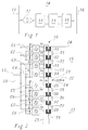
- FIG. 2 An exemplary construction of an inverter 15 is shown in FIG. 2.
- the inverter 15 of this example comprises 8 inverter bridges B1, .., B8 operating in parallel, each of which is connected to the input lines 17, 18 coming from the DC voltage intermediate circuit 14 with a parallel capacitor C1, .., C8.
- a transformer 19 is provided, which contains a pair of windings for each of the inverter bridges B1, .., B8 from a primary winding P1, .., P8 and a secondary winding S1, .., S8 .
- the outputs of the inverter bridges B1, .., B8 are each connected to the corresponding primary windings P1, .., P8, the secondary windings S1, .., S8 are connected in series.
- the summed output signal is available on the output lines 20, 21.
- the transformer 19 can additionally be equipped with tertiary windings T1, .., T8, which are connected in series and are damped by a corresponding filter circuit 25 (see, for example, EP-B1-0 149 169).
- Exemplary permanently modulated and phase-shifted pulse series for the inverter bridges B1, .., B8 are shown in FIG. 3.
- the resulting sum voltage u Bi in FIG. 4 results from the summation of the individual pulse sequences in the transformer 19.
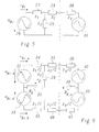
- the impedances 27 and 28 with the values z 1 and z 2 represent the transformer 19, the impedance 29 with the value z 3 represents the filter circuit 25.
- the rail network 16 can be represented in the equivalent circuit diagram by the impedance 30 (z 4 ) and the voltage source 31 describe.
- the equivalent circuit diagram of the VSC from FIG. 5 can be converted into an equivalent circuit diagram according to FIG. 6 by grounding (via the resistor 22) at the center tap 23 of the transformer 19.
- the impedances 27 and 28 of the transformer 19 are shown in FIG. 6 now divided into impedances 34 and 39 or 35 and 40, each with half the original impedance value, namely z 1/2 and z 2/2.
- the impedance 29 with the value z3 is maintained, while the impedance 30 and the voltage source 31 to the rail system 16 is also divided in the impedances 36 and 41 (in each case with the value z 4/2) or voltage sources 42 and 43.
- the grounding via the center tap 23 of the transformer 19 is represented in FIG. 6 by the resistor 37 with the value R E.
- a corresponding resistor 38 with the value R E, r describes the total remote earthing resistance of the rail network 16.
- the equivalent circuit diagram of FIG. 6 can be broken down into two superimposed subsystems, namely the common mode system and the push-pull system (differential mode system). ). The two superimposed systems can then be treated separately from one another and the resulting currents and voltages can simply be added after the end of the analysis to obtain the real physical quantities.
- the equivalent circuit diagram in the common mode system for the upper half of the VSC is shown in FIG. 7.
- resistors 45 and 46 in the circuit, which each make up twice the grounding resistors 37 and 38, respectively.
- the voltage source 44 outputs a voltage u Bi, CM which drives a current i Bi, CM through the circuit.
- the equivalent circuit diagram in the push-pull system for the upper half of the VSC is shown in FIG. 8.
- the impedance 48 is also present here, which corresponds to half the impedance 29 and is characteristic of the filter circuit 25.
- the voltage source 47 outputs a voltage u Bi, D which drives a current i Bi, D through the circuit.
- the object is achieved in an inverter of the type mentioned at the outset in that for damping or suppression of in-phase or common-mode interference currents flowing via the ground connection within the transformer, the secondary windings are each divided into a first and second similar partial-secondary winding, and that Partial secondary windings are connected to one another and to the center tap in such a way that the common mode voltages induced in the partial secondary windings cancel each other out.
- the particular advantage of the solution according to the invention is that common-mode voltage components u Bi, CM or common-mode current components are avoided without the spectral quality of the push-pull voltage u Bi, D or the push-pull currents being impaired in any way.
- a preferred embodiment of the invention stands out characterized in that the first partial secondary windings a first Series connection that form the second part-secondary windings a second parallel to the first series connection Series connection form that the top output of the first Series connection that forms an output of the inverter and the lower output of the second series connection the other Output of the inverter forms, and that the lower Output of the first series connection and the upper output of the second series connection merged at the center tap are.
- An inverter according to the invention is preferred in one Converter with DC link, especially in a traction current converter or a frequency coupling.
- FIG. 9 is a preferred embodiment for one Inverter reproduced according to the invention.
- the inverter of FIG. 9 is essentially the same in construction the inverter of FIG. 2.
- the secondary windings in the transformer 19 divided into two Similar secondary windings S11, S12; ...; S81, S82.
- the first (upper) partial secondary windings S11, .., S81 are connected in series and form a first series connection with the outputs A1 (top) and A3 (below).
- the second (lower) partial secondary windings S12, .., S82 are also connected in series and form a parallel to the first series connection second series connection with the outputs A2 (top) and A4 (below).
Abstract
Description
Die vorliegende Erfindung bezieht sich auf das Gebiet der Leistungselektronik. Sie betrifft einen Wechselrichter, umfassend eine Mehrzahl von aus der selben Gleichspannungsquelle parallel arbeitenden Wechselrichterbrücken, deren Ausgangsspannungen über einen Transformator aufsummiert werden, welcher eine der Anzahl der Wechselrichterbrücken entsprechende Anzahl von Primärwicklungen und zugehörigen Sekundärwicklungen aufweist, wobei jede Wechselrichterbrücke jeweils ausgangsseitig an eine Primärwicklung angeschlossen ist, und die Sekundärwicklungen zur Summation der Ausgangsspannungen in Serie geschaltet sind, und wobei die Wechselrichterbrücken jeweils nach Massgabe einer Hilfssteuerspannung pulsdauermoduliert angesteuert werden und die Hilfssteuerspannungen der einzelnen Wechselrichterbrücken untereinander eine konstante Phasendifferenz aufweisen, und wobei der Transformator einen Mittelabgriff aufweist, welcher über eine Erdverbindung geerdet ist. The present invention relates to the field of Power electronics. It relates to an inverter, comprehensively a plurality of from the same DC voltage source parallel working inverter bridges, their Output voltages are summed up via a transformer, which corresponds to the number of inverter bridges Number of primary windings and associated secondary windings each inverter bridge each connected to a primary winding on the output side and the secondary windings for the summation of the output voltages are connected in series, and the inverter bridges in accordance with an auxiliary control voltage pulse duration modulated and the auxiliary control voltages of the individual inverter bridges with each other have a constant phase difference, and wherein the Transformer has a center tap, which has a Earth connection is earthed.
Zur Verbindung von Stromnetzen mit unterschiedlicher Phasenzahl
und/oder Wechselspannungsfrequenz, wie z.B. zwischen einem
50Hz-Drehstromnetz und einem einphasigen 16 2/3Hz-Bahnnetz,
werden zunehmend mit Leistungshalbleitern ausgerüstete
vollstatische Kupplungen bzw. Bahnstromumrichter eingesetzt,
die häufig als Umrichter mit Gleichspannungszwischenkreis
ausgebildet sind. Gemäss Fig. 1 umfasst ein solcher Bahnstromumrichter
10 beispielsweise einen (thyristorbestückten)
Stromrichter 13, der über einen Transformator 12 den Drehstrom
aus dem Drehstromnetz 11 abnimmt und in einen Gleichstrom
umwandelt, einen Gleichspannungszwischenkreis 14 zur
Glättung bzw. Zwischenspeicherung, und einen Wechselrichter
15, der den Gleichstrom wieder in einen Wechselstrom der gewünschten
Frequenz umwandelt und in das Bahnnetz 16 einspeist.For connecting power grids with different phases
and / or AC voltage frequency, e.g. between one
50Hz three-phase network and a single-
Im Wechselrichter 15 werden üblicherweise eine oder mehrere
parallel arbeitende Wechselrichterbrücken mit schaltbaren
Ventilen (z.B. GTOs) eingesetzt, die pulsdauermoduliert angesteuert
werden und die gewünschte sinusförmige Ausgangsspannung
durch eine Abfolge von dauermodulierten Rechteckimpulsen
wechselnder Polarität approximieren. Zur Pulsdauermodulation
wird dabei üblicherweise eine dreieckförmige Hilfssteuerspannung
verwendet. Einzelheiten der Ansteuerung können beispielsweise
einem Sonderdruck (Nr. 9608-1000-0) der Anmelderin,
"Vollstatische 100-MW-Frequenzkupplung Bremen", entnommen
werden. Werden mehrere Wechselrichterbrücken parallel betrieben,
werden die Ausgangsspannungen aufsummiert. Eine Verringerung
des Oberschwingungsgehalts wird dabei dadurch erreicht,
dass die Ansteuerung der einzelnen Wechselrichterbrücken
über die Hilfssteuerspannungen phasenverschoben erfolgt.Usually one or more are in the
Ein beispielhafter Aufbau eines Wechselrichters 15 ist in
Fig. 2 wiedergegeben. Der Wechselrichter 15 dieses Beispiels
umfasst 8 parallel arbeitende Wechselrichterbrücken B1,..,B8,
die jeweils mit einem parallelen Kondensator C1,..,C8 am Eingang
an die vom Gleichspannungszwischenkreis 14 kommenden
Eingangsleitungen 17, 18 angeschlossen sind. Zur Summation
der Ausgangsspannungen der Wechselrichterbrücken B1,..,B8 ist
ein Transformator 19 vorgesehen, der für jede der Wechselrichterbrücken
B1,..,B8 ein Wicklungspaar aus einer Primärwicklung
P1,..,P8 und einer Sekundärwicklung S1,..,S8 enthält.
Die Ausgänge der Wechselrichterbrücken B1,..,B8 sind
jeweils an die entsprechenden Primärwicklungen P1,..,P8 angeschlossen,
die Sekundärwicklungen S1,..,S8 sind in Reihe geschaltet.
Das summierte Ausgangssignal steht an den Ausgangsleitungen
20, 21 zur Verfügung. Zur Unterdrückung von Oberschwingungen
kann der Transformator 19 zusätzlich mit Tertiärwicklungen
T1,..,T8 ausgestattet sein, die in Reihe geschaltet
und durch eine entsprechende Filterschaltung 25 bedämpft
sind (siehe dazu beispielsweise die EP-B1-0 149 169).
Beispielhafte dauermodulierte und phasenverschobene Impulsreihen
für die Wechselrichterbrücken B1,..,B8 sind in Fig. 3
wiedergegeben. Durch Summation der einzelnen Impulsfolgen im
Transformator 19 ergibt sich daraus die resultierende Summenspannung
uBi in Fig. 4.An exemplary construction of an
Probleme mit der in Fig. 2 dargestellten Art von Wechselrichter
ergeben sich nun, wenn - wie es bei manchen Bahnnetzen
erforderlich ist - der Transformator 19 des Wechselrichters
15 an einem Mittelabgriff 23 durch eine Erdverbindung 24 über
einen Widerstand 22 (oder auch ohne Widerstand, d.h. "hart")
geerdet wird (siehe Fig. 2). Diese Probleme lassen sich anhand
der in Fig. 5 bis 8 wiedergegebenen Ersatzschaltbilder
verdeutlichen: Der Wechselrichter, der als Spannungsquellenumrichter
(Voltage Source Converter, VSC) arbeitet, kann
grundsätzlich (Fig. 5) durch eine Spannungsquelle 26 mit der
Spannung uBi beschrieben werden, die einen entsprechenden
Strom iBi durch einen Kreis treibt, der durch die Impedanzen
27, 28 und 29 gebildet wird. Die Impedanzen 27 und 28 mit den
Werten z1 bzw. z2 repräsentieren den Transformator 19, die
Impedanz 29 mit dem Wert z3 repräsentiert die Filterschaltung
25. Das Bahnnetz 16 lässt sich im Ersatzschaltbild durch die
Impedanz 30 (z4) und die Spannungsquelle 31 beschreiben.Problems now arise with the type of inverter shown in FIG. 2 if - as is required in some rail networks - the
Durch die Erdung (über den Widerstand 22) am Mittelabgriff 23
des Transformators 19 kann das Ersatzschaltbild des VSC aus
Fig. 5 in ein Ersatzschaltbild gemäss Fig. 6 überführt werden.
Die Spannungsquelle 26 ist hier in zwei Spannungsquellen
32 und 33 mit den Teilspannungen uBi,a und uBi,b aufgeteilt,
wobei gilt:
Die Impedanzen 27 und 28 des Transformators 19 sind in Fig. 6
nun aufgeteilt in Impedanzen 34 und 39 bzw. 35 und 40 mit jeweils
der Hälfte des ursprünglichen Impedanzwertes, nämlich
z1/2 und z2/2. Die Impedanz 29 mit dem Wert z3 bleibt erhalten,
während die Impedanz 30 und die Spannungsquelle 31 des
Bahnnetzes 16 ebenfalls aufgeteilt werden in die Impedanzen
36 und 41 (jeweils mit dem Wert z4/2) bzw. Spannungsquellen
42 und 43. Die Erdung über den Mittelabgriff 23 des Transformators
19 wird in Fig. 6 durch den Widerstand 37 mit dem Wert
RE repräsentiert. Ein entsprechender Widerstand 38 mit dem
Wert RE,r beschreibt den gesamten Fern-Erdungswiderstand des
Bahnnetzes 16. The
Nach dem Konzept der modalen Zerlegung ("Modal Decomposition")
kann das Ersatzschaltbild der Fig. 6 in zwei überlagerte
Teilsysteme zerlegt werden, nämlich in das Gleichtakt-System
("Common Mode System") und das Gegentakt-System
("Differential Mode System"). Die beiden überlagerten Systeme
können dann getrennt voneinander behandelt und die resultierenden
Ströme und Spannungen nach Beendigung der Analyse einfach
addiert werden, um die realen physikalischen Grössen zu
erhalten. Das Ersatzschaltbild im Gleichtakt-System für die
obere Hälfte des VSC ist in Fig. 7 wiedergegeben. Neben den
bereits bekannten Impedanzen 34, 35 und 36 befinden sich im
Stromkreis die Widerstände 45 und 46, welche jeweils das Doppelte
der Erdungswiderstände 37 bzw. 38 ausmachen. Die Spannungsquelle
44 gibt eine Spannung uBi,CM ab, die einen Strom
iBi,CM durch den Kreis treibt. Das Ersatzschaltbild im Gegentakt-System
für die obere Hälfte des VSC ist in Fig. 8 dargestellt.
Neben den bereits bekannten Impedanzen 34, 35 und 36
ist hier zusätzlich die Impedanz 48 vorhanden, welche der
halben Impedanz 29 entspricht und für die Filterschaltung 25
charakteristisch ist. Die Spannungsquelle 47 gibt eine Spannung
uBi,D ab, die einen Strom iBi,D durch den Kreis treibt.According to the concept of modal decomposition, the equivalent circuit diagram of FIG. 6 can be broken down into two superimposed subsystems, namely the common mode system and the push-pull system (differential mode system). ). The two superimposed systems can then be treated separately from one another and the resulting currents and voltages can simply be added after the end of the analysis to obtain the real physical quantities. The equivalent circuit diagram in the common mode system for the upper half of the VSC is shown in FIG. 7. In addition to the already known
Für die Spannungen und Ströme ergibt sich der folgende Zusammenhang:
Aus den Fig. 5 bis 8 und den Gleichungen (1) bis (5) ergibt sich unmittelbar, dass die Gleichtaktspannung uBi,CM unerwünscht ist, weil sie einen Gleichtaktstrom iBi,CM treibt, der nur durch die Erdungswiderstände 37 und 38 zurückfliessen kann. Die Höhe des Gleichtaktstromes iBi,CM ist hauptsächlich durch die Impedanzen z1 und z2 des Transformators 19 begrenzt. Der Gleichtaktstrom iBi,CM hat zwei nachteilige Wirkungen:
- Er bewirkt erhebliche Verluste sowohl im
lokalen Erdungswiderstand 22 bzw. 37 als auch im Fern-Erdungswiderstand 38. Wie Simulationen einer realen Anlage (Leistung ca. 50 MW) zeigen, können die Verluste im Erdungswiderstand 22 (bei einem nominalen Widerstandswert von RE = 334 Ω) ungefähr 50kW betragen und sind daher von einer unakzeptablen Grössenordnung. - Er kann in dem Bahnnetz (z.B. einem 138kV-Netz) Störungen in benachbarten Kommunikationseinrichtungen hervorrufen.
- It causes considerable losses both in the
local earth resistance remote earth resistance 38. As simulations of a real system (output approx. 50 MW) show, the losses in the earth resistance 22 (with a nominal resistance value of R E = 334) Ω) are approximately 50kW and are therefore of an unacceptable order of magnitude. - In the rail network (eg a 138 kV network) it can cause interference in neighboring communication facilities.
Es ist daher Aufgabe der Erfindung, einen VSC-Wechselrichter zu schaffen, bei welchem die über die Erdverbindung fliessenden Ströme unterdrückt bzw. auf einen unschädlichen Wert gedämpft werden.It is therefore an object of the invention to provide a VSC inverter to create, in which the flowing over the earth connection Currents suppressed or to a harmless value be dampened.
Die Aufgabe wird bei einem Wechselrichter der eingangs genannten Art dadurch gelöst, dass zur Dämpfung bzw. Unterdrückung von über die Erdverbindung fliessenden gleichphasigen bzw. Gleichtakt-Störströmen innerhalb des Transformators die Sekundärwicklungen jeweils in eine erste und zweite gleichartige Teil-Sekundärwicklung aufgeteilt sind, und die Teil-Sekundärwicklungen so untereinander und mit dem Mittelabgriff verbunden sind, dass sich die in den Teil-Sekundärwicklungen induzierten Gleichtaktspannungen gegenseitig aufheben. Der besondere Vorteil der erfindungsgemässen Lösung besteht darin, dass Gleichtaktspannungskomponenten uBi,CM bzw. Gleichtaktstromkomponenten vermieden werden, ohne dass die spektrale Qualität der Gegentaktspannung uBi,D bzw. der Gegentaktströme in irgendeiner Weise beeinträchtigt wird.The object is achieved in an inverter of the type mentioned at the outset in that for damping or suppression of in-phase or common-mode interference currents flowing via the ground connection within the transformer, the secondary windings are each divided into a first and second similar partial-secondary winding, and that Partial secondary windings are connected to one another and to the center tap in such a way that the common mode voltages induced in the partial secondary windings cancel each other out. The particular advantage of the solution according to the invention is that common-mode voltage components u Bi, CM or common-mode current components are avoided without the spectral quality of the push-pull voltage u Bi, D or the push-pull currents being impaired in any way.
Eine bevorzugte Ausführungsform der Erfindung zeichnet sich dadurch aus, dass die ersten Teil-Sekundärwicklungen eine erste Reihenschaltung bilden, dass die zweiten Teil-Sekundärwicklungen eine zur ersten Reihenschaltung parallele zweite Reihenschaltung bilden, dass der obere Ausgang der ersten Reihenschaltung den einen Ausgang des Wechselrichters bildet und der untere Ausgang der zweiten Reihenschaltung den anderen Ausgang des Wechselrichters bildet, und dass der untere Ausgang der ersten Reihenschaltung und der obere Ausgang der zweiten Reihenschaltung am Mittelabgriff zusammengeführt sind.A preferred embodiment of the invention stands out characterized in that the first partial secondary windings a first Series connection that form the second part-secondary windings a second parallel to the first series connection Series connection form that the top output of the first Series connection that forms an output of the inverter and the lower output of the second series connection the other Output of the inverter forms, and that the lower Output of the first series connection and the upper output of the second series connection merged at the center tap are.
Bevorzugt wird ein Wechselrichter nach der Erfindung in einem Umrichter mit Gleichspannungszwischenkreis, insbesondere in einem Bahnstromumrichter oder einer Frequenz kupplung, eingesetzt.An inverter according to the invention is preferred in one Converter with DC link, especially in a traction current converter or a frequency coupling.
Die Erfindung soll nachfolgend anhand von Ausführungsbeispielen im Zusammenhang mit der Zeichnung näher erläutert werden. Es zeigen
- Fig. 1
- den prinzipiellen Aufbau eines Bahnstromumrichters;
- Fig. 2
- das Blockschaltbild eines für den Bahnstromumrichter nach Fig. 1 geeigneten Wechselrichters mit einer Mehrzahl von parallelen Wechselrichterbrücken und mit Mittelpunktserdung des Transformators;
- Fig. 3
- beispielhafte pulsdauermodulierte Ausgangsimpulsfolgen der einzelnen Wechselrichterbrücken aus Fig. 2;
- Fig. 4
- die sich durch Aufsummierung der Ausgangsimpulsfolgen aus Fig. 3 ergebende Summenspannung;
- Fig. 5
- das Ersatzschaltbild des mit dem Bahnnetz verbundenen Wechselrichters aus Fig. 4 ohne Mittelpunktserdung des Transformators;
- Fig. 6
- das zu Fig. 5 entsprechende Ersatzschaltbild bei vorhandener Mittelpunktserdung;
- Fig. 7
- das aus dem Ersatzschaltbild der Fig. 6 abgeleitete Ersatzschaltbild für das Gleichtakt-Teilsystem;
- Fig. 8
- das aus dem Ersatzschaltbild der Fig. 6 abgeleitete Ersatzschaltbild für das Gegentakt-Teilsystem;
- Fig. 9
- ein bevorzugtes Ausführungsbeispiel für einen Wechselrichter nach der Erfindung mit einer Aufteilung der Sekundärwicklungen des Wechselrichter-Transformators in Teil-Sekundärwicklungen und einer speziellen Verschaltung der Teil-Sekundärwicklungen.
- Fig. 1
- the basic structure of a traction current converter;
- Fig. 2
- the block diagram of a suitable for the traction current converter of Figure 1 inverter with a plurality of parallel inverter bridges and with center grounding of the transformer.
- Fig. 3
- exemplary pulse duration modulated output pulse sequences of the individual inverter bridges from FIG. 2;
- Fig. 4
- the sum voltage resulting from the summation of the output pulse sequences from FIG. 3;
- Fig. 5
- the equivalent circuit diagram of the inverter connected to the rail network of Figure 4 without grounding the center of the transformer.
- Fig. 6
- the equivalent circuit diagram corresponding to FIG. 5 with existing center earthing;
- Fig. 7
- the equivalent circuit diagram derived from the equivalent circuit diagram in FIG. 6 for the common mode subsystem;
- Fig. 8
- the equivalent circuit diagram derived from the equivalent circuit diagram in FIG. 6 for the push-pull subsystem;
- Fig. 9
- a preferred embodiment of an inverter according to the invention with a division of the secondary windings of the inverter transformer into partial secondary windings and a special connection of the partial secondary windings.
In der Fig. 9 ist ein bevorzugtes Ausführungsbeispiel für einen
Wechselrichter nach der Erfindung wiedergegeben. Der
Wechselrichter der Fig. 9 gleicht in seinem Aufbau im wesentlichen
dem Wechselrichter der Fig. 2. Anstelle der einen Sekundärwicklung
S1,..,S8 pro Wechselrichterbrücke werden hier
die Sekundärwicklungen im Transformator 19 unterteilt in zwei
gleichartige Teil-Sekundärwicklungen S11, S12;...; S81, S82.
Die jeweils ersten (oberen) Teil-Sekundärwicklungen
S11,..,S81 sind hintereinander in Reihe geschaltet und bilden
eine erste Reihenschaltung mit den Ausgängen A1 (oben) und A3
(unten). Die jeweils zweiten (unteren) Teil-Sekundärwicklungen
S12,..,S82 sind ebenfalls hintereinander in Reihe geschaltet
und bilden parallel zur ersten Reihenschaltung eine
zweite Reihenschaltung mit den Ausgängen A2 (oben) und A4
(unten).9 is a preferred embodiment for one
Inverter reproduced according to the invention. Of the
The inverter of FIG. 9 is essentially the same in construction
the inverter of FIG. 2. Instead of the one secondary winding
S1, .., S8 per inverter bridge are here
the secondary windings in the
Die durch die Erdverbindung 24 und den ggf. vorhandenen Erdungswiderstand
22 fliessenden Gleichtaktströme bzw. die dazugehörigen
Gleichtaktspannungen werden nun dadurch ausgeschaltet,
dass der obere Ausgang Al der ersten Reihenschaltung
aus den Teil-Sekundärwicklungen S11,..,S81 den einen
Ausgang des Wechselrichters 15 bildet und der untere Ausgang
A4 der zweiten Reihenschaltung aus den Teil-Sekundärwicklungen
S12,..,S82 den anderen Ausgang des Wechselrichters 15
bildet, und dass der untere Ausgang A3 der ersten Reihenschaltung
und der obere Ausgang A2 der zweiten Reihenschaltung
am Mittelabgriff 23 des Transformators 19 zusammengeführt
sind.The through the
Durch diese Art des Aufteilens und Zusammenschaltens der Sekundärwicklungen
wird erreicht, dass
Da durch diese Art des Aufbaus des am Mittelabgriff geerdeten
Transformators 19 die unerwünschten Gleichtaktspannungen
praktisch vollständig beseitigt werden, ohne dass die Gegentaktspannungen
negativ beeinflusst werden, wird gemäss der
Erfindung durch eine vergleichsweise einfache Aenderung des
Transformators ein maximaler Unterdrückungseffekt erzielt.Because by this type of construction of the grounded at the
- 1010th
- BahnstromumrichterTraction current converter
- 1111
- DrehstromnetzThree-phase network
- 1212th
- Transformator (3-phasig)Transformer (3-phase)
- 1313
- StromrichterPower converter
- 1414
- GleichspannungszwischenkreisDC link
- 1515
- WechselrichterInverter
- 1616
- BahnnetzRailway network
- 17,1817.18
- Eingangsleitung (Wechselrichter)Input line (inverter)
- 1919th
- Transformator (Wechselrichter) Transformer
- 20,2120.21
- Ausgangsleitung (Wechselrichter)Output line (inverter)
- 2222
- Widerstandresistance
- 2323
- Mittelabgriff (Transformator)Center tap (transformer)
- 2424th
- ErdverbindungEarth connection
- 2525th
- FilterschaltungFilter circuit
- 26,3126.31
- SpannungsquelleVoltage source
- 27,..,3027, .., 30
- ImpedanzImpedance
- 32,3332.33
- SpannungsquelleVoltage source
- 34,..,3634, .., 36
- ImpedanzImpedance
- 37,3837.38
- Widerstandresistance
- 39,..,4139, .., 41
- ImpedanzImpedance
- 42,4342.43
- SpannungsquellenVoltage sources
- 44,4744.47
- SpannungsquelleVoltage source
- 45,4645.46
- Widerstandresistance
- 4848
- ImpedanzImpedance
- A1,..,A4A1, .., A4
- Ausgangexit
- B1, .,B8B1,., B8
- WechselrichterbrückeInverter bridge
- C1,..,C8C1, .., C8
- Kondensatorcapacitor
- P1,..,P8P1, .., P8
- PrimärwicklungPrimary winding
- S1,..,S8S1, .., S8
- SekundärwicklungSecondary winding
- S11,..,S82S11, .., S82
- Teil-SekundärwicklungPartial secondary winding
- T1,..,T8T1, .., T8
- TertiärwicklungTertiary winding
Claims (3)
Applications Claiming Priority (2)
| Application Number | Priority Date | Filing Date | Title |
|---|---|---|---|
| DE19736613A DE19736613A1 (en) | 1997-08-22 | 1997-08-22 | Inverter |
| DE19736613 | 1997-08-22 |
Publications (2)
| Publication Number | Publication Date |
|---|---|
| EP0898359A2 true EP0898359A2 (en) | 1999-02-24 |
| EP0898359A3 EP0898359A3 (en) | 1999-10-20 |
Family
ID=7839876
Family Applications (1)
| Application Number | Title | Priority Date | Filing Date |
|---|---|---|---|
| EP98810736A Withdrawn EP0898359A3 (en) | 1997-08-22 | 1998-07-30 | Inverter |
Country Status (6)
| Country | Link |
|---|---|
| US (1) | US5999428A (en) |
| EP (1) | EP0898359A3 (en) |
| KR (1) | KR19990023780A (en) |
| DE (1) | DE19736613A1 (en) |
| NO (1) | NO983809L (en) |
| ZA (1) | ZA987064B (en) |
Cited By (2)
| Publication number | Priority date | Publication date | Assignee | Title |
|---|---|---|---|---|
| WO2004064240A1 (en) | 2003-01-15 | 2004-07-29 | Siemens Aktiengesellschaft | Method for reducing common-mode interference currents in an electric drive system, and corresponding electric drive system |
| CN104852387A (en) * | 2015-05-11 | 2015-08-19 | 西南交通大学 | Active compensation cophase supply system based on modular cascaded H bridge |
Families Citing this family (11)
| Publication number | Priority date | Publication date | Assignee | Title |
|---|---|---|---|---|
| DE19736612A1 (en) * | 1997-08-22 | 1999-02-25 | Asea Brown Boveri | Inverter |
| GB2330254B (en) * | 1997-10-09 | 2000-10-18 | Toshiba Kk | Multiple inverter system |
| US6377478B1 (en) | 1999-05-28 | 2002-04-23 | Toshiba International Corporation | Inverter device |
| GB2354121B (en) * | 1999-09-09 | 2001-07-25 | Donald Watson Bingley | Improvements in or relating to inverters |
| EP1195877B1 (en) * | 2000-10-06 | 2018-09-12 | ABB Schweiz AG | Inverter system with dc-link connected inverter modules and method of operation |
| JP4112930B2 (en) * | 2002-09-04 | 2008-07-02 | 東芝三菱電機産業システム株式会社 | Inverter device |
| EP2164159B1 (en) * | 2008-09-12 | 2019-02-20 | Vestas Wind Systems A/S | Low-voltage harmonic filter for full-scale converter systems |
| KR20120057577A (en) * | 2009-05-07 | 2012-06-05 | 지멘스 악티엔게젤샤프트 | Method of adapting a configuration of a voltage converting device and voltage converting unit for a voltage converting device |
| ES2402462B1 (en) * | 2010-11-08 | 2014-03-28 | Ingeteam Technology, S.A | Control method for energy conversion, and electronic power converter adapted to carry out said method |
| RU2515474C2 (en) * | 2011-05-17 | 2014-05-10 | Хонда Мотор Ко., Лтд. | Inverter generator |
| WO2018233822A1 (en) * | 2017-06-21 | 2018-12-27 | Abb Schweiz Ag | Model based current control of a three-to-single-phase power converter |
Citations (5)
| Publication number | Priority date | Publication date | Assignee | Title |
|---|---|---|---|---|
| US2779926A (en) * | 1954-01-25 | 1957-01-29 | Gen Electric | Transformer with five-leg core |
| US3611224A (en) * | 1967-08-24 | 1971-10-05 | Licentia Gmbh | Controllable reactive current generator |
| US3628123A (en) * | 1970-03-11 | 1971-12-14 | Westinghouse Electric Corp | Apparatus for harmonic neutralization of inverters |
| US5006783A (en) * | 1989-10-16 | 1991-04-09 | General Signal Corporation | Three phase voltage regulator system using tertiary winding transformer |
| US5057808A (en) * | 1989-12-27 | 1991-10-15 | Sundstrand Corporation | Transformer with voltage balancing tertiary winding |
Family Cites Families (5)
| Publication number | Priority date | Publication date | Assignee | Title |
|---|---|---|---|---|
| US4159513A (en) * | 1977-09-30 | 1979-06-26 | Westinghouse Electric Corp. | Static controlled AC motor drive having plug reversal capability |
| US4426678A (en) * | 1982-05-28 | 1984-01-17 | The United States Of America As Represented By The Administrator Of The National Aeronautics And Space Administration | D.C. to D.C. converter |
| DE3602496A1 (en) * | 1986-01-28 | 1987-07-30 | Klein Kg Elektro Geraete G | Method for the parallel operation of invertors, and an invertor arrangement for carrying out the method |
| US5065303A (en) * | 1990-07-24 | 1991-11-12 | Sundstrand Corporation | Transformer-coupled and phase-shifted inverter |
| US5508905A (en) * | 1992-08-06 | 1996-04-16 | Metropolitan Pump Company | Low distortion variable output power supply |
-
1997
- 1997-08-22 DE DE19736613A patent/DE19736613A1/en not_active Withdrawn
-
1998
- 1998-07-30 EP EP98810736A patent/EP0898359A3/en not_active Withdrawn
- 1998-08-06 ZA ZA987064A patent/ZA987064B/en unknown
- 1998-08-19 NO NO983809A patent/NO983809L/en not_active Application Discontinuation
- 1998-08-21 KR KR1019980033978A patent/KR19990023780A/en not_active Application Discontinuation
- 1998-08-21 US US09/137,746 patent/US5999428A/en not_active Expired - Fee Related
Patent Citations (5)
| Publication number | Priority date | Publication date | Assignee | Title |
|---|---|---|---|---|
| US2779926A (en) * | 1954-01-25 | 1957-01-29 | Gen Electric | Transformer with five-leg core |
| US3611224A (en) * | 1967-08-24 | 1971-10-05 | Licentia Gmbh | Controllable reactive current generator |
| US3628123A (en) * | 1970-03-11 | 1971-12-14 | Westinghouse Electric Corp | Apparatus for harmonic neutralization of inverters |
| US5006783A (en) * | 1989-10-16 | 1991-04-09 | General Signal Corporation | Three phase voltage regulator system using tertiary winding transformer |
| US5057808A (en) * | 1989-12-27 | 1991-10-15 | Sundstrand Corporation | Transformer with voltage balancing tertiary winding |
Cited By (4)
| Publication number | Priority date | Publication date | Assignee | Title |
|---|---|---|---|---|
| WO2004064240A1 (en) | 2003-01-15 | 2004-07-29 | Siemens Aktiengesellschaft | Method for reducing common-mode interference currents in an electric drive system, and corresponding electric drive system |
| KR101144364B1 (en) | 2003-01-15 | 2012-05-11 | 지멘스 악티엔게젤샤프트 | Method for reducing common-mode interference currents in an electric drive system, and corresponding electric drive system |
| CN104852387A (en) * | 2015-05-11 | 2015-08-19 | 西南交通大学 | Active compensation cophase supply system based on modular cascaded H bridge |
| CN104852387B (en) * | 2015-05-11 | 2017-06-13 | 西南交通大学 | A kind of active compensation cophase supply system based on modularization cascaded H-bridges |
Also Published As
| Publication number | Publication date |
|---|---|
| DE19736613A1 (en) | 1999-02-25 |
| NO983809D0 (en) | 1998-08-19 |
| EP0898359A3 (en) | 1999-10-20 |
| US5999428A (en) | 1999-12-07 |
| KR19990023780A (en) | 1999-03-25 |
| ZA987064B (en) | 1999-02-08 |
| NO983809L (en) | 1999-02-23 |
Similar Documents
| Publication | Publication Date | Title |
|---|---|---|
| EP0903843B1 (en) | Inverter | |
| EP0899859B1 (en) | Intermediate voltage link inverter | |
| DE102005012371A1 (en) | Twelve-pulse high-voltage direct-current meeting | |
| EP0898359A2 (en) | Inverter | |
| DE19913634C2 (en) | Device for controlling switchable semiconductor switches of a line-side converter of a voltage intermediate circuit converter | |
| DE10128152B4 (en) | Ship propulsion system with reduced on-board distortion | |
| DE102007047165A1 (en) | power supply | |
| EP0212172B1 (en) | Current oscillations compensation method and device | |
| EP0898358A2 (en) | Inverter | |
| EP0682402B1 (en) | Output magnitudes rise limiting device for self-commutated constant voltage intermediate circuit converter | |
| CH641610A5 (en) | ROTARY CONTROL SYSTEM. | |
| CH642493A5 (en) | TRANSMISSION SYSTEM FOR HIGH VOLTAGE DC. | |
| EP0115814B1 (en) | Arrangement for feeding audio frequency signals into a power distribution network | |
| EP0584660B1 (en) | Method and circuit arrangement for reduction of harmonics | |
| DE102004002261A1 (en) | Kommutierungsfilter | |
| DE102018208626A1 (en) | Magnetically adjustable reactor for reactive power compensation with capacitively connected auxiliary windings | |
| EP3827510B1 (en) | Frequency inverter with simplified precharging circuit | |
| EP0967109A1 (en) | Substation for power supply to two sections of an electrified railway network | |
| DE4025685A1 (en) | Rectifying circuit protecting mains against transformer harmonics - utilises star connections of phase-shifted sec. windings for integration of parasitic capacitances into filter circuits | |
| EP0763833A2 (en) | Transformer for an electrically driven vehicle | |
| DE3045574A1 (en) | Static reactive power compensator coupled to transformer secondary - has additional transformer between mains transformer secondary and thyristor chokes, with phase-variable secondaries | |
| DE329364C (en) | Transformer with m magnetic legs for changing the number of phases n of a multi-phase system | |
| DE19646085A1 (en) | Power converter circuitry | |
| DE3004521A1 (en) | CIRCUIT BREAKER SYSTEM | |
| DE595177C (en) | Device for connecting consumers, in particular those with low power requirements, to a high-voltage network or a high-voltage line with the aid of transformers |
Legal Events
| Date | Code | Title | Description |
|---|---|---|---|
| PUAI | Public reference made under article 153(3) epc to a published international application that has entered the european phase |
Free format text: ORIGINAL CODE: 0009012 |
|
| AK | Designated contracting states |
Kind code of ref document: A2 Designated state(s): AT CH DE LI SE |
|
| AX | Request for extension of the european patent |
Free format text: AL;LT;LV;MK;RO;SI |
|
| PUAL | Search report despatched |
Free format text: ORIGINAL CODE: 0009013 |
|
| AK | Designated contracting states |
Kind code of ref document: A3 Designated state(s): AT BE CH CY DE DK ES FI FR GB GR IE IT LI LU MC NL PT SE |
|
| AX | Request for extension of the european patent |
Free format text: AL;LT;LV;MK;RO;SI |
|
| 17P | Request for examination filed |
Effective date: 20000318 |
|
| RAP1 | Party data changed (applicant data changed or rights of an application transferred) |
Owner name: ABB AG (ABB SA) (ABB LTD) |
|
| RAP1 | Party data changed (applicant data changed or rights of an application transferred) |
Owner name: ABB (SCHWEIZ) AG |
|
| AKX | Designation fees paid |
Free format text: AT CH DE LI SE |
|
| RAP1 | Party data changed (applicant data changed or rights of an application transferred) |
Owner name: ABB INDUSTRIE AG |
|
| RAP1 | Party data changed (applicant data changed or rights of an application transferred) |
Owner name: ABB SCHWEIZ AG |
|
| STAA | Information on the status of an ep patent application or granted ep patent |
Free format text: STATUS: THE APPLICATION HAS BEEN WITHDRAWN |
|
| 18W | Application withdrawn |
Effective date: 20030303 |