EP0878850A2 - Photovoltaic power generation apparatus - Google Patents
Photovoltaic power generation apparatus Download PDFInfo
- Publication number
- EP0878850A2 EP0878850A2 EP98108351A EP98108351A EP0878850A2 EP 0878850 A2 EP0878850 A2 EP 0878850A2 EP 98108351 A EP98108351 A EP 98108351A EP 98108351 A EP98108351 A EP 98108351A EP 0878850 A2 EP0878850 A2 EP 0878850A2
- Authority
- EP
- European Patent Office
- Prior art keywords
- solar cell
- cell array
- power generation
- generation apparatus
- circuit breaker
- Prior art date
- Legal status (The legal status is an assumption and is not a legal conclusion. Google has not performed a legal analysis and makes no representation as to the accuracy of the status listed.)
- Withdrawn
Links
- 238000010248 power generation Methods 0.000 title claims abstract description 60
- 239000002184 metal Substances 0.000 claims description 22
- 229910052751 metal Inorganic materials 0.000 claims description 22
- 230000003014 reinforcing effect Effects 0.000 claims description 13
- 238000000034 method Methods 0.000 claims description 7
- 239000000758 substrate Substances 0.000 claims description 5
- 239000004566 building material Substances 0.000 claims description 2
- 239000004065 semiconductor Substances 0.000 claims description 2
- 230000035945 sensitivity Effects 0.000 abstract description 14
- 238000001514 detection method Methods 0.000 abstract description 11
- 238000009434 installation Methods 0.000 abstract description 2
- 238000002474 experimental method Methods 0.000 description 19
- 239000000463 material Substances 0.000 description 13
- 229920005989 resin Polymers 0.000 description 10
- 239000011347 resin Substances 0.000 description 10
- 238000013461 design Methods 0.000 description 7
- 229910021417 amorphous silicon Inorganic materials 0.000 description 4
- 238000006243 chemical reaction Methods 0.000 description 4
- 238000010586 diagram Methods 0.000 description 4
- 230000000694 effects Effects 0.000 description 3
- 239000005038 ethylene vinyl acetate Substances 0.000 description 3
- 238000005259 measurement Methods 0.000 description 3
- 238000000819 phase cycle Methods 0.000 description 3
- 229920001200 poly(ethylene-vinyl acetate) Polymers 0.000 description 3
- 229920002430 Fibre-reinforced plastic Polymers 0.000 description 2
- 239000003990 capacitor Substances 0.000 description 2
- 230000005611 electricity Effects 0.000 description 2
- 238000005538 encapsulation Methods 0.000 description 2
- 229920006244 ethylene-ethyl acrylate Polymers 0.000 description 2
- 229920006225 ethylene-methyl acrylate Polymers 0.000 description 2
- 239000011151 fibre-reinforced plastic Substances 0.000 description 2
- 239000011521 glass Substances 0.000 description 2
- 230000001681 protective effect Effects 0.000 description 2
- 230000009993 protective function Effects 0.000 description 2
- 230000009467 reduction Effects 0.000 description 2
- 239000004925 Acrylic resin Substances 0.000 description 1
- 229920000178 Acrylic resin Polymers 0.000 description 1
- XUIMIQQOPSSXEZ-UHFFFAOYSA-N Silicon Chemical compound [Si] XUIMIQQOPSSXEZ-UHFFFAOYSA-N 0.000 description 1
- KTSFMFGEAAANTF-UHFFFAOYSA-N [Cu].[Se].[Se].[In] Chemical compound [Cu].[Se].[Se].[In] KTSFMFGEAAANTF-UHFFFAOYSA-N 0.000 description 1
- 238000005452 bending Methods 0.000 description 1
- 125000004063 butyryl group Chemical group O=C([*])C([H])([H])C([H])([H])C([H])([H])[H] 0.000 description 1
- 238000005229 chemical vapour deposition Methods 0.000 description 1
- 238000004891 communication Methods 0.000 description 1
- 150000001875 compounds Chemical class 0.000 description 1
- 229910021419 crystalline silicon Inorganic materials 0.000 description 1
- QHSJIZLJUFMIFP-UHFFFAOYSA-N ethene;1,1,2,2-tetrafluoroethene Chemical group C=C.FC(F)=C(F)F QHSJIZLJUFMIFP-UHFFFAOYSA-N 0.000 description 1
- 239000005042 ethylene-ethyl acrylate Substances 0.000 description 1
- 238000004519 manufacturing process Methods 0.000 description 1
- 238000007620 mathematical function Methods 0.000 description 1
- 238000012986 modification Methods 0.000 description 1
- 230000004048 modification Effects 0.000 description 1
- 230000003287 optical effect Effects 0.000 description 1
- 229920003023 plastic Polymers 0.000 description 1
- 239000004033 plastic Substances 0.000 description 1
- 229910021420 polycrystalline silicon Inorganic materials 0.000 description 1
- 229920000098 polyolefin Polymers 0.000 description 1
- 230000008569 process Effects 0.000 description 1
- 238000011160 research Methods 0.000 description 1
- 230000004044 response Effects 0.000 description 1
- 229910052710 silicon Inorganic materials 0.000 description 1
- 239000010703 silicon Substances 0.000 description 1
- 238000003860 storage Methods 0.000 description 1
- 229920002803 thermoplastic polyurethane Polymers 0.000 description 1
- 230000000007 visual effect Effects 0.000 description 1
Images


Classifications
-
- H—ELECTRICITY
- H02—GENERATION; CONVERSION OR DISTRIBUTION OF ELECTRIC POWER
- H02S—GENERATION OF ELECTRIC POWER BY CONVERSION OF INFRARED RADIATION, VISIBLE LIGHT OR ULTRAVIOLET LIGHT, e.g. USING PHOTOVOLTAIC [PV] MODULES
- H02S50/00—Monitoring or testing of PV systems, e.g. load balancing or fault identification
-
- H—ELECTRICITY
- H02—GENERATION; CONVERSION OR DISTRIBUTION OF ELECTRIC POWER
- H02J—CIRCUIT ARRANGEMENTS OR SYSTEMS FOR SUPPLYING OR DISTRIBUTING ELECTRIC POWER; SYSTEMS FOR STORING ELECTRIC ENERGY
- H02J3/00—Circuit arrangements for ac mains or ac distribution networks
- H02J3/38—Arrangements for parallely feeding a single network by two or more generators, converters or transformers
-
- G—PHYSICS
- G01—MEASURING; TESTING
- G01R—MEASURING ELECTRIC VARIABLES; MEASURING MAGNETIC VARIABLES
- G01R31/00—Arrangements for testing electric properties; Arrangements for locating electric faults; Arrangements for electrical testing characterised by what is being tested not provided for elsewhere
- G01R31/50—Testing of electric apparatus, lines, cables or components for short-circuits, continuity, leakage current or incorrect line connections
-
- H—ELECTRICITY
- H01—ELECTRIC ELEMENTS
- H01L—SEMICONDUCTOR DEVICES NOT COVERED BY CLASS H10
- H01L31/00—Semiconductor devices sensitive to infrared radiation, light, electromagnetic radiation of shorter wavelength or corpuscular radiation and specially adapted either for the conversion of the energy of such radiation into electrical energy or for the control of electrical energy by such radiation; Processes or apparatus specially adapted for the manufacture or treatment thereof or of parts thereof; Details thereof
- H01L31/02—Details
- H01L31/02016—Circuit arrangements of general character for the devices
- H01L31/02019—Circuit arrangements of general character for the devices for devices characterised by at least one potential jump barrier or surface barrier
- H01L31/02021—Circuit arrangements of general character for the devices for devices characterised by at least one potential jump barrier or surface barrier for solar cells
-
- H—ELECTRICITY
- H01—ELECTRIC ELEMENTS
- H01L—SEMICONDUCTOR DEVICES NOT COVERED BY CLASS H10
- H01L31/00—Semiconductor devices sensitive to infrared radiation, light, electromagnetic radiation of shorter wavelength or corpuscular radiation and specially adapted either for the conversion of the energy of such radiation into electrical energy or for the control of electrical energy by such radiation; Processes or apparatus specially adapted for the manufacture or treatment thereof or of parts thereof; Details thereof
- H01L31/04—Semiconductor devices sensitive to infrared radiation, light, electromagnetic radiation of shorter wavelength or corpuscular radiation and specially adapted either for the conversion of the energy of such radiation into electrical energy or for the control of electrical energy by such radiation; Processes or apparatus specially adapted for the manufacture or treatment thereof or of parts thereof; Details thereof adapted as photovoltaic [PV] conversion devices
- H01L31/042—PV modules or arrays of single PV cells
- H01L31/048—Encapsulation of modules
-
- H—ELECTRICITY
- H01—ELECTRIC ELEMENTS
- H01L—SEMICONDUCTOR DEVICES NOT COVERED BY CLASS H10
- H01L31/00—Semiconductor devices sensitive to infrared radiation, light, electromagnetic radiation of shorter wavelength or corpuscular radiation and specially adapted either for the conversion of the energy of such radiation into electrical energy or for the control of electrical energy by such radiation; Processes or apparatus specially adapted for the manufacture or treatment thereof or of parts thereof; Details thereof
- H01L31/04—Semiconductor devices sensitive to infrared radiation, light, electromagnetic radiation of shorter wavelength or corpuscular radiation and specially adapted either for the conversion of the energy of such radiation into electrical energy or for the control of electrical energy by such radiation; Processes or apparatus specially adapted for the manufacture or treatment thereof or of parts thereof; Details thereof adapted as photovoltaic [PV] conversion devices
- H01L31/042—PV modules or arrays of single PV cells
- H01L31/05—Electrical interconnection means between PV cells inside the PV module, e.g. series connection of PV cells
-
- H—ELECTRICITY
- H02—GENERATION; CONVERSION OR DISTRIBUTION OF ELECTRIC POWER
- H02H—EMERGENCY PROTECTIVE CIRCUIT ARRANGEMENTS
- H02H3/00—Emergency protective circuit arrangements for automatic disconnection directly responsive to an undesired change from normal electric working condition with or without subsequent reconnection ; integrated protection
- H02H3/006—Calibration or setting of parameters
-
- H—ELECTRICITY
- H02—GENERATION; CONVERSION OR DISTRIBUTION OF ELECTRIC POWER
- H02H—EMERGENCY PROTECTIVE CIRCUIT ARRANGEMENTS
- H02H3/00—Emergency protective circuit arrangements for automatic disconnection directly responsive to an undesired change from normal electric working condition with or without subsequent reconnection ; integrated protection
- H02H3/26—Emergency protective circuit arrangements for automatic disconnection directly responsive to an undesired change from normal electric working condition with or without subsequent reconnection ; integrated protection responsive to difference between voltages or between currents; responsive to phase angle between voltages or between currents
- H02H3/32—Emergency protective circuit arrangements for automatic disconnection directly responsive to an undesired change from normal electric working condition with or without subsequent reconnection ; integrated protection responsive to difference between voltages or between currents; responsive to phase angle between voltages or between currents involving comparison of the voltage or current values at corresponding points in different conductors of a single system, e.g. of currents in go and return conductors
- H02H3/33—Emergency protective circuit arrangements for automatic disconnection directly responsive to an undesired change from normal electric working condition with or without subsequent reconnection ; integrated protection responsive to difference between voltages or between currents; responsive to phase angle between voltages or between currents involving comparison of the voltage or current values at corresponding points in different conductors of a single system, e.g. of currents in go and return conductors using summation current transformers
-
- H—ELECTRICITY
- H02—GENERATION; CONVERSION OR DISTRIBUTION OF ELECTRIC POWER
- H02H—EMERGENCY PROTECTIVE CIRCUIT ARRANGEMENTS
- H02H7/00—Emergency protective circuit arrangements specially adapted for specific types of electric machines or apparatus or for sectionalised protection of cable or line systems, and effecting automatic switching in the event of an undesired change from normal working conditions
- H02H7/20—Emergency protective circuit arrangements specially adapted for specific types of electric machines or apparatus or for sectionalised protection of cable or line systems, and effecting automatic switching in the event of an undesired change from normal working conditions for electronic equipment
-
- H—ELECTRICITY
- H02—GENERATION; CONVERSION OR DISTRIBUTION OF ELECTRIC POWER
- H02S—GENERATION OF ELECTRIC POWER BY CONVERSION OF INFRARED RADIATION, VISIBLE LIGHT OR ULTRAVIOLET LIGHT, e.g. USING PHOTOVOLTAIC [PV] MODULES
- H02S20/00—Supporting structures for PV modules
- H02S20/20—Supporting structures directly fixed to an immovable object
- H02S20/22—Supporting structures directly fixed to an immovable object specially adapted for buildings
- H02S20/26—Building materials integrated with PV modules, e.g. façade elements
-
- H—ELECTRICITY
- H02—GENERATION; CONVERSION OR DISTRIBUTION OF ELECTRIC POWER
- H02S—GENERATION OF ELECTRIC POWER BY CONVERSION OF INFRARED RADIATION, VISIBLE LIGHT OR ULTRAVIOLET LIGHT, e.g. USING PHOTOVOLTAIC [PV] MODULES
- H02S40/00—Components or accessories in combination with PV modules, not provided for in groups H02S10/00 - H02S30/00
- H02S40/30—Electrical components
- H02S40/32—Electrical components comprising DC/AC inverter means associated with the PV module itself, e.g. AC modules
-
- Y—GENERAL TAGGING OF NEW TECHNOLOGICAL DEVELOPMENTS; GENERAL TAGGING OF CROSS-SECTIONAL TECHNOLOGIES SPANNING OVER SEVERAL SECTIONS OF THE IPC; TECHNICAL SUBJECTS COVERED BY FORMER USPC CROSS-REFERENCE ART COLLECTIONS [XRACs] AND DIGESTS
- Y02—TECHNOLOGIES OR APPLICATIONS FOR MITIGATION OR ADAPTATION AGAINST CLIMATE CHANGE
- Y02E—REDUCTION OF GREENHOUSE GAS [GHG] EMISSIONS, RELATED TO ENERGY GENERATION, TRANSMISSION OR DISTRIBUTION
- Y02E10/00—Energy generation through renewable energy sources
- Y02E10/50—Photovoltaic [PV] energy
- Y02E10/56—Power conversion systems, e.g. maximum power point trackers
Definitions
- the present invention relates to a photovoltaic power generation apparatus, and designing and installing thereof.
- Photovoltaic power generation apparatuses for housing use have begun to spread, and researches aimed at cost reduction of the apparatuses have been actively performed.
- a solar cell module integrated with a roof material, which unnecessitates a rack, and a non-insulated type inverter, i.e., so-called transless inverter, are being considered for practical use.
- Efficiency of a transless inverter is high and it is inexpensive, therefore, transless inverters are widely used recently.
- Fig. 1 is a block diagram illustrating a configuration of a photovoltaic power generation apparatus which can be tied to a general power system.
- Electric power is supplied from a solar cell array 1 to a commercial AC power system 3 and/or a load 6 of a customer, supplying electricity, via an inverter 2.
- earth leakage circuit breakers 4a and 4b are provided, and, when a leakage of electricity occurs in a house or building of the customer, the commercial AC power system 3 is completely disconnected.
- the solar cell array 1 requires a considerably wide outdoor area for installing it, e.g., the solar cell array 1 of 3kW generation capability requires an area of about 30m 2 , there is considerably large earth capacitance 5 of the solar cell array 1. Accordingly, there is a fear, as pointed out by Furukawa et al. in the national meeting of the Institute of Electrical Engineers of Japan, Industry Application Society in 1996 (article No. 77), that small leak current flows via the earth capacitance 5 and may unnecessarily activate the earth leakage circuit breaker 4a or 4b (i.e., interrupt the circuit).
- the load 6 is disconnected from the commercial AC power system 3 and an interruption to service occurs. Further, in a case where the earth leakage circuit breaker 4b is activated, photovoltaic power is disconnected, therefore, the electric power generated by the solar cell array 1 is wasted.
- the present invention has been made in consideration of the above situation, and has as its object to provide a photovoltaic power generation apparatus capable of preventing an earth leakage circuit breaker from undesirably operating, and designing and installing the apparatus.
- a photovoltaic power generation apparatus used in connection with a commercial AC power system, the apparatus comprising: a solar cell array; a non-insulated type inverter for converting direct-current electric power outputted from the solar cell array into alternating-current electric power; and an earth leakage circuit breaker provided between the non-insulated type inverter and the commercial AC power system, wherein stray capacitance Ca[ ⁇ F] of the solar cell array with respect to a ground potential and circuit breaker interrupting rating EL[mA] of the earth leakage circuit breaker have a relationship of Ca ⁇ EL/3.
- a photovoltaic power generation apparatus used in connection with a commercial AC power system, comprising a solar cell array, a non-insulated type inverter for converting direct-current electric power outputted from the solar cell array into alternating-current electric power, and an earth leakage circuit breaker provided between the non-insulated type inverter and the commercial AC power system, the method comprising the steps of: measuring or estimating stray capacitance Ca[ ⁇ F] of the solar cell array with respect to a ground potential; and setting circuit breaker interrupting rating EL[mA] of the earth leakage circuit breaker so that relationship of Ca ⁇ EL/3 holds.
- a chart used for designing or installing a photovoltaic power generation apparatus used in connection with a commercial AC power system, comprising a solar cell array, a non-insulated type inverter for converting direct-current electric power outputted from the solar cell array into alternating-current electric power, and an earth leakage circuit breaker provided between the non-insulated type inverter and the commercial AC power system, wherein relationship between number of solar cell modules forming the solar cell array and leak current flowing via stray capacitance of the solar cell array with respect to a ground potential is recorded in the chart.
- a chart used for designing or installing a photovoltaic power generation apparatus used in connection with a commercial AC power system, comprising a solar cell array, a non-insulated type inverter for converting direct-current electric power outputted from the solar cell array into alternating-current electric power, and an earth leakage circuit breaker provided between the non-insulated type inverter and the commercial AC power system, wherein relationship between rated power generation of the solar cell array and leak current flowing via stray capacitance of the solar cell array with respect to a ground potential is recorded in the chart.
- a photovoltaic power generation apparatus of the present invention referring to Fig. 1, the number of solar cell modules configuring a solar cell array 1, and/or circuit breaker interrupting rating of earth leakage circuit breakers 4a and 4b are determined so that stray capacitance Ca[ ⁇ F] of the solar cell array 1 with respect to a ground potential (referred to as "earth capacitance” hereinafter), and leak current detection sensitivity EL[mA] of the earth leakage circuit breakers 4a and 4b have relationship of Ca ⁇ EL/3. Then, the photovoltaic power generation apparatus of the present invention is configured on the basis of the determined result.
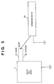
- the earth capacitance Ca of the solar cell array 1 can be measured, as shown in Fig. 5, by shorting an anode 31 and a cathode 32 of the solar cell array 1, and connecting an impedance meter 30 between the shorted node between the anode 31 and the cathode 32 and a metal reinforcing plate which is a roof material, for instance.
- the solar cell array 1 includes a plurality of solar cell modules connected in series and/or parallel.
- As the solar cell module a unit encapsulated and sealed on a reinforced plate, as a roof material, with a resin is preferably used.
- a solar cell As a solar cell, a crystalline silicon solar cell, a polycrystalline silicon solar cell, and an amorphous silicon solar cell, or a compound semiconductor solar cell, such as a copper indium selenide solar cell, may be used. Especially, it is advantageous to use the amorphous silicon solar cell formed by chemical vapor deposition on a long metal substrate to reduce manufacturing cost.
- FRP fiber reinforced plastics
- polyolefine resin such as ethylene-vinyl acetate copolymer (EVA), ethylene-methyl acrylate copolymer (EMA), ethylene-ethyl acrylate copolymer (EEA), and butyryl resin, urethane resin, and silicon resin may be used.
- EVA ethylene-vinyl acetate copolymer
- EMA ethylene-methyl acrylate copolymer
- EAA ethylene-ethyl acrylate copolymer
- butyryl resin urethane resin
- silicon resin silicon resin
- the surface of the solar cell module is coated by a transparent resin film, such as a fluororesin film and an acrylic resin film, as a protective coat.
- resins for the encapsulation and seal and for the film those having high sunlight transmissivity characteristics are preferred.
- the solar cell module may be used as a building material, such as a wall material and a roof material, by bending to process the metal reinforcing plate.
- Figs. 8A to 8C show examples of integrated roof solar cell modules.
- Fig. 8A shows a roof material having a ridge engagement portion 81 and an eaves engagement portion 82 which are bent to the opposite directions;
- Fig. 8B shows a roof material whose engagement portions 83 are inserted and engaged by fixed members 84 fixed on a roof board 85;
- Fig. 8C shows roof materials whose engagement portions 86 of adjoining pairs of the roof materials are held together by caps 87.
- the solar cell module 80 is provided on the photo-receiving surface of each roof material shown in Figs. 8A to 8C.
- the circumference is preferably reinforced by a metal frame.
- the inverter 2 is a transless inverter which does not use an insulating transformer between the direct-current side (the side of the solar cell array 1) and the alternating-current side (the side of the commercial AC power system 3 and the load 6). Since no transformer is used, the transless inverter has great advantages of high conversion efficiency, light weight, and low cost. However, because the commercial AC power system 3 is grounded, the transless inverter on the direct-current side can not be insulated from the commercial AC power system 3.
- the earth leakage circuit breakers 4a and 4b detect zero-phase-sequence current which is the total of current flowing through a plurality of wires which form a circuit, and when the zero-phase-sequence current exceeds the circuit breaker interrupting rating (leak current detection sensitivity) EL, the earth leakage circuit breakers interrupt the circuit. Further, when the zero-phase-sequence current is smaller than non-operating current rating, namely, in a dead band of the earth leakage circuit breakers, then the earth leakage circuit breakers do not interrupt the circuit. Generally, the value of the non-operating current rating is set to half the value of the circuit breaker interrupting rating EL.
- the solar cell array 1 is formed by connecting 100 solar cell modules 9 (Fig. 2).
- the solar cell array 1 is installed on a metal rack on the ground with a slope of 30 degrees, facing to the south.
- Fig. 2 is a cross-sectional view of the solar cell module 9, and an amorphous solar cell 11 is encapsulated and sealed on a metal reinforcing plate 10 with a resin 12, such as an EVA resin.
- a resin 12 such as an EVA resin.
- the surface of the solar cell module is coated with a protective film 13, such as an ethylene tetra fluoro-ethylene (ETFE) film.
- ETFE ethylene tetra fluoro-ethylene
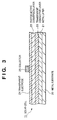
- Fig. 3 is a cross-sectional view of the amorphous solar cell 11 which is formed in such a manner that a metal layer 21, a transparent conductive layer 22, a photoelectric conversion layer 23, a transparent electrode 24, and a collector 25 are stacked on a metal substrate 20.
- the photoelectric conversion layer 23 is formed by stacking a pin junction of three-layer amorphous silicon.
- inverter 2 a transless-type inverter (available from Toshiba Corp., Product Type PVUL0035) is used.
- earth leakage circuit breakers 4a and 4b those whose leak current detection sensitivity EL is 15mA, non-operating current rating is less than 7.5mA, and rated current is 30A (available from Matsusita Electric Works, Ltd., Product Type BJJ330225K) are used. These earth leakage circuit breakers are connected to the commercial AC power system 3 (60Hz, 200V) to form a photovoltaic power generation apparatus for the experiment.
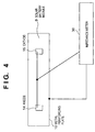
- Capacitance Cx of each solar cell module 9 is measured by the impedance meter 30 (available from Hioki E. E. Corp., Product Type 3520 LCR-Hi-TESTER) which is connected between a shorted node between the anode 14 and the cathode 15 and the metal reinforcing plate 10, as shown in Fig. 4.
- the measured capacitance Cx of the solar cell module 9 (width: 45cm, length: 130cm) was 20nF.
- 120Hz which is a ripple frequency of the inverter 2 is selected.
- the earth capacitance Ca of the solar cell array 1 was measured and it was 2 ⁇ F, which is just 100 times larger than the capacitance Cx of each solar cell module 9.
- the earth capacitance Ca of the solar cell array can be measured between the metal frame which is grounded, and the shorted node between electric output terminals of the solar cell array.
- the photovoltaic power generation apparatus installed as described above was run for a month, and the earth leakage circuit breakers were not activated during this period.
- the number of the solar cell modules forming the solar cell array 1 was reduced to 100, then film capacitors of 1.5 ⁇ F were provided between the anode 31 and the ground, and between the cathode 32 and the ground, providing a total capacitance of 3 ⁇ F. With this configuration, the earth capacitance Ca of the solar cell array 1 was 5 ⁇ F. Within four weeks of the experiment, the earth leakage circuit breakers were undesirably activated once.
- the solar cell array 1 is set on the roof of a building, and the earth capacitance Ca is changed by changing the rated power generation of the solar cell array, i.e., by changing the number of the solar cell modules 9 forming the solar cell array 1. Then, with the different numbers of the solar cell modules 9, leak current is measured to clarify that the leak current falls within a dead band (generally, less than 50% of the leak current detection sensitivity EL. When the leak current detection sensitivity EL is 30mA, the dead band is held less than 15mA) of earth leakage by designing the photovoltaic power generation apparatus on the basis of the results of the experiment 1. As for the inverter 2, an inverter of different type from that used in the experiment 1 is selected so as to prove that the photovoltaic power generation apparatus of the present invention gives essential the same effect regardless of the type of the inverter 2.
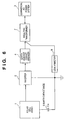
- Fig. 6 is a block diagram illustrating a configuration of the photovoltaic power generation apparatus used in the experiment 2.
- a transless inverter available from Japan Storage Battery Co., Ltd., Product Name of LINEBACK-EX is used as the inverter 2.
- the solar cell array 1 has 696 integrated roof solar cell modules, each shown in Fig. 8A, arranged in 58 strings, each including 12 modules connected in series, and the strings connected in parallel.
- the configuration of the solar cell 80 is the same as that used in the experiment 1 except that the photoelectric conversion layer is formed by staking a pin junction of two-layer amorphous silicon.
- the capacitance Cx of each roof solar cell module is about the same as that of the solar cell module 9 used in the experiment 1.
- the area of the solar cell array 1 using the aforesaid roof solar cell modules is about 300m 2 .
- the measured earth capacitance Cs of a string of the solar cell modules i.e., 12 modules connected in series
- an earth leakage circuit breaker 4 As an earth leakage circuit breaker 4, a breaker of rated current of 50A, leak current detection sensitivity of 30mA, and non-operating current rating of 15mA (available from Matsusita Electric Works, Ltd., Product Type BJ35025K1) was selected, and connected to the commercial AC power system 3 of 60Hz and 200V via an insulating transformer 7.
- the reason for using the insulating transformer 7 is to make it possible for a leak ammeter 8 to measure leak current in the secondary side (i.e., the side of the solar cell array 1) of the insulating transformer 7, and there is no impact to the embodiment of the present invention. In other words, for operating the photovoltaic power generation apparatus of the present invention in practice, the insulating transformer 7 is not used.
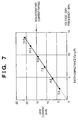
- the rated power generation of the solar cell array 1 was increased by 10 strings, namely, the earth capacitance Ca was increased by 2.4 ⁇ F, and respective leak current (frequency of equal or less than 1kHz) was recorded.
- the reason for setting the frequency range for measuring the leak current to equal or less than 1kHz was due to the frequency range of sensitivity of the earth leakage circuit breaker which was set to equal or less than 1kHz.
- Fig. 7 is a graph showing the measurement results of leak current with respect to the earth capacitance Ca obtained as described above. Note, numerals written by square points on a straight line in the graph indicates the number of connected strings of the solar cell modules.
- a photovoltaic power generation apparatus designed on the basis of the knowledge obtained from the experiments 1 and 2 provides following effects.
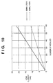
- the leak current detection sensitivity EL and/or the non-operating current rating of the earth leakage circuit breaker of the photovoltaic power generation apparatus of the present invention is designed on the basis of the graph (design chart) shown in Fig. 7, based on the results of the experiments 1 and 2. Further, a design chart in Fig. 10 shows relationship between the number or rated power generation of the solar cell modules used in a solar panel, and the leak current. A designer or installer of the photovoltaic power generation apparatus is able to determine leak current of the photovoltaic power generation apparatus to be designed or installed from the design chart shown in Fig.
- the design charts shown in Figs. 7 and 10 are not always provided in a visual form recorded on a medium, such as paper.
- a medium such as paper.
- the present invention as information showing relationship between earth capacitance of a solar panel, or the number or the rated power generation of the solar cell modules, and leak current, as a table or a mathematical functions in a form of program codes or data recorded on magnetic recording media or optical recording media used in a computer, or exchanged via communication media.
- media which can be used by a computer as measure media of the above, carry program codes or data showing information on relationship between the earth capacitance of the solar panel or the number or the rated power generation of the solar cell modules, and the leak current, the media also configure the present invention.
- Figs. 7 and 10 have voltage and frequency of commercial AC power system as parameters. Further, it is apparent for those who are skilled in the art that the name or the type of the solar cell module may be also included as parameters.
- a solar cell array used in a photovoltaic power generation apparatus for housing covers a relatively large outside area for installation, and a considerably large earth capacitance Ca exists between the solar cell array and the ground. Further, as an inverter for converting direct-current electric power generated by the solar cell array into alternating-current electric power, a transless-type inverter is used for reducing cost. Therefore, a slight leak current flows via the earth capacitance Ca, which may cause undesirable operation of an earth leakage circuit breaker inserted between the inverter and a commercial AC power system.
- the photovoltaic power generation apparatus of the present invention by designing it so that relationship between the earth capacitance Ca[ ⁇ F] and leak current detection sensitivity EL[mA] of the earth leakage circuit breaker has Ca ⁇ EL/3, the undesirable operation of the earth leakage circuit breaker due to the leak current is prevented.
Abstract
Description
Claims (12)
- A photovoltaic power generation apparatus used in connection with a commercial AC power system, said apparatus comprising:a solar cell array;a non-insulated type inverter for converting direct-current electric power outputted from said solar cell array into alternating-current electric power; andan earth leakage circuit breaker provided between said non-insulated type inverter and the commercial AC power system,wherein stray capacitance Ca[µF] of said solar cell array with respect to a ground potential and circuit breaker interrupting rating EL[mA] of said earth leakage circuit breaker have a relationship of Ca < EL/3.
- The photovoltaic power generation apparatus according to claim 1, wherein said solar cell array includes a plurality of solar cell modules each of which has solar cells fixed on a reinforcing plate.
- The photovoltaic power generation apparatus according to claim 2, wherein said reinforcing plate is made of metal.
- The photovoltaic power generation apparatus according to claim 2, wherein said solar cells are formed on a metal substrate.
- The photovoltaic power generation apparatus according to claim 2, wherein said solar cells have non-crystalline semiconductor.
- The photovoltaic power generation apparatus according to claim 2, wherein said solar cell module forms a building material.
- A designing or installing method of a photovoltaic power generation apparatus, used in connection with a commercial AC power system, comprising a solar cell array, a non-insulated type inverter for converting direct-current electric power outputted from said solar cell array into alternating-current electric power, and an earth leakage circuit breaker provided between said non-insulated type inverter and the commercial AC power system, said method comprising the steps of:measuring or estimating stray capacitance Ca[µF] of said solar cell array with respect to a ground potential; andsetting circuit breaker interrupting rating EL[mA] of said earth leakage circuit breaker so that relationship of Ca < EL/3 holds.
- A chart used for designing or installing a photovoltaic power generation apparatus, used in connection with a commercial AC power system, comprising a solar cell array, a non-insulated type inverter for converting direct-current electric power outputted from said solar cell array into alternating-current electric power, and an earth leakage circuit breaker provided between said non-insulated type inverter and the commercial AC power system,wherein relationship between number of solar cell modules forming said solar cell array and leak current flowing via stray capacitance of said solar cell array with respect to a ground potential is recorded in said chart.
- The chart according to claim 8, wherein the relationship between the number of the solar cell modules and the leak current is recorded, using frequency and voltage of the commercial AC power system as parameters.
- A chart used for designing or installing a photovoltaic power generation apparatus, used in connection with a commercial AC power system, comprising a solar cell array, a non-insulated type inverter for converting direct-current electric power outputted from said solar cell array into alternating-current electric power, and an earth leakage circuit breaker provided between said non-insulated type inverter and the commercial AC power system,wherein relationship between rated power generation of said solar cell array and leak current flowing via stray capacitance of said solar cell array with respect to a ground potential is recorded in said chart.
- The chart according to claim 10, wherein the relationship between the rated power generation of said solar cell array and the leak current is recorded, using a type of solar cell modules forming said solar cell array as parameters.
- The chart according to claim 10, wherein the relationship between the rated power generation of said solar cell array and the leak current is recorded, using frequency and voltage of the commercial AC power system as parameters.
Applications Claiming Priority (3)
| Application Number | Priority Date | Filing Date | Title |
|---|---|---|---|
| JP123989/97 | 1997-05-14 | ||
| JP9123989A JPH10322885A (en) | 1997-05-14 | 1997-05-14 | Solar beam power generating unit |
| JP12398997 | 1997-05-14 |
Publications (2)
| Publication Number | Publication Date |
|---|---|
| EP0878850A2 true EP0878850A2 (en) | 1998-11-18 |
| EP0878850A3 EP0878850A3 (en) | 2000-05-10 |
Family
ID=14874293
Family Applications (1)
| Application Number | Title | Priority Date | Filing Date |
|---|---|---|---|
| EP98108351A Withdrawn EP0878850A3 (en) | 1997-05-14 | 1998-05-07 | Photovoltaic power generation apparatus |
Country Status (6)
| Country | Link |
|---|---|
| US (1) | US6107560A (en) |
| EP (1) | EP0878850A3 (en) |
| JP (1) | JPH10322885A (en) |
| KR (1) | KR100316132B1 (en) |
| CN (1) | CN1092845C (en) |
| AU (1) | AU724559B2 (en) |
Cited By (16)
| Publication number | Priority date | Publication date | Assignee | Title |
|---|---|---|---|---|
| EP1104070A2 (en) * | 1999-11-29 | 2001-05-30 | Canon Kabushiki Kaisha | Power generation system, and method for installing the same |
| EP1107439A2 (en) * | 1999-12-01 | 2001-06-13 | Canon Kabushiki Kaisha | Interconnection power converter and power generation apparatus using the same |
| US6259017B1 (en) * | 1998-10-15 | 2001-07-10 | Canon Kabushiki Kaisha | Solar power generation apparatus and control method therefor |
| EP1143594A2 (en) * | 2000-03-29 | 2001-10-10 | Canon Kabushiki Kaisha | Power converting apparatus, control method therefor, and solar power generation apparatus |
| GB2424118A (en) * | 2005-03-12 | 2006-09-13 | Acal Energy Ltd | Fuel Cells |
| GB2436403A (en) * | 2006-03-20 | 2007-09-26 | Solar Century Holdings Ltd | Earthing unit for solar panel array |
| US8492048B2 (en) | 2006-07-19 | 2013-07-23 | Acal Energy Limited | Fuel cells |
| US8603684B2 (en) | 2007-09-20 | 2013-12-10 | Acal Energy Limited | Fuel cells |
| US8647781B2 (en) | 2008-01-23 | 2014-02-11 | Acal Energy Limited | Redox fuel cells |
| US8753783B2 (en) | 2006-04-25 | 2014-06-17 | ACAL Enegy Limited | Fuel cells with improved resistance to fuel crossover |
| DE102013202926A1 (en) * | 2013-02-22 | 2014-08-28 | Siemens Aktiengesellschaft | Arrangement of photovoltaic module array, has filter arrangement designed such that alternating current harmonics abutting against direct current input of inverter is suppressed and not allowed to pass toward module array |
| US8951695B2 (en) | 2008-01-23 | 2015-02-10 | Acal Energy Limited | Redox fuel cell with catholyte redox mediator |
| US9005828B2 (en) | 2006-03-24 | 2015-04-14 | Acal Energy Limited | Redox fuel cells with a catholyte solution containing a polyoxometallate |
| US9029042B2 (en) | 2007-09-24 | 2015-05-12 | Acal Energy Limited | Redox fuel cell |
| US9136554B2 (en) | 2006-07-19 | 2015-09-15 | Acal Energy Limited | Fuel cells |
| DE102017129083A1 (en) | 2017-12-06 | 2019-06-06 | Sma Solar Technology Ag | Fail-safe operating method for a decentralized power generation plant |
Families Citing this family (26)
| Publication number | Priority date | Publication date | Assignee | Title |
|---|---|---|---|---|
| JP4463963B2 (en) * | 2000-09-29 | 2010-05-19 | キヤノン株式会社 | Grid interconnection device |
| JP2002354678A (en) | 2001-05-29 | 2002-12-06 | Canon Inc | Power generating device, and its control method |
| JP2003158282A (en) * | 2001-08-30 | 2003-05-30 | Canon Inc | Solar photovoltaic power-generation system |
| JP4167872B2 (en) * | 2001-10-04 | 2008-10-22 | 株式会社日立産機システム | Leakage current monitoring device and monitoring system therefor |
| US7353123B2 (en) * | 2001-10-04 | 2008-04-01 | Hitachi, Ltd. | Leakage current or resistance measurement method, and monitoring apparatus and monitoring system of the same |
| KR20030065098A (en) * | 2002-01-30 | 2003-08-06 | 어익수 | AC/DC Solar Lighting System for the Apartment and House |
| US7612283B2 (en) * | 2002-07-09 | 2009-11-03 | Canon Kabushiki Kaisha | Solar power generation apparatus and its manufacturing method |
| JP2004179637A (en) * | 2002-11-14 | 2004-06-24 | Canon Inc | Solar cell module |
| JP2004336944A (en) * | 2003-05-09 | 2004-11-25 | Canon Inc | Power converter and phtovolatic generation system |
| US20050139259A1 (en) * | 2003-12-30 | 2005-06-30 | Robert Steigerwald | Transformerless power conversion in an inverter for a photovoltaic system |
| DE102004025924A1 (en) * | 2004-05-27 | 2005-12-22 | Siemens Ag | Solar inverter and photovoltaic system with several solar inverters |
| KR100809482B1 (en) * | 2007-10-25 | 2008-03-07 | 이현화 | Solar photovoltatic generation system with three phase circuit breaker |
| US8933320B2 (en) | 2008-01-18 | 2015-01-13 | Tenksolar, Inc. | Redundant electrical architecture for photovoltaic modules |
| WO2009092110A2 (en) * | 2008-01-18 | 2009-07-23 | Tenksolar, Inc. | Redundant electrical architecture for photovoltaic modules |
| WO2010030409A1 (en) * | 2008-04-04 | 2010-03-18 | Zingher Arthur R | Scalable dense pv solar receiver for high concentration |
| US8274805B2 (en) * | 2008-04-08 | 2012-09-25 | Samsung Electro-Mechanics Co., Ltd. | High voltage power supply |
| JP4612731B1 (en) * | 2009-09-29 | 2011-01-12 | 富士フイルム株式会社 | Solar cell module |
| US9773933B2 (en) | 2010-02-23 | 2017-09-26 | Tenksolar, Inc. | Space and energy efficient photovoltaic array |
| US20130300428A1 (en) * | 2010-03-31 | 2013-11-14 | Sma Solar Technology Ag | Determination of a Stray Capacitance of an AC Current Generator |
| ES2565005T3 (en) | 2010-03-31 | 2016-03-30 | Sma Solar Technology Ag | Determination of the part of the fault current of a differential current |
| EP2553737A4 (en) * | 2010-04-01 | 2015-05-20 | Morgan Solar Inc | An integrated photovoltaic module |
| US9299861B2 (en) | 2010-06-15 | 2016-03-29 | Tenksolar, Inc. | Cell-to-grid redundandt photovoltaic system |
| KR101470349B1 (en) * | 2014-08-20 | 2014-12-15 | 주식회사 코텍에너지 | Photovoltaic power generation system equipped with apparatus having a function of detecting grounding or the leakage current |
| JP6161584B2 (en) * | 2014-09-27 | 2017-07-12 | オリジン電気株式会社 | Power conditioner and connection method thereof |
| CN106787110A (en) * | 2017-01-10 | 2017-05-31 | 国家电网公司 | A kind of breaker angle of solar battery system controls power supply |
| JP6709743B2 (en) * | 2017-01-30 | 2020-06-17 | 京セラ株式会社 | Power converter and control method thereof |
Citations (1)
| Publication number | Priority date | Publication date | Assignee | Title |
|---|---|---|---|---|
| EP0768721A2 (en) * | 1995-10-11 | 1997-04-16 | Canon Kabushiki Kaisha | Solar cell module and manufacturing method thereof |
Family Cites Families (6)
| Publication number | Priority date | Publication date | Assignee | Title |
|---|---|---|---|---|
| GB8906885D0 (en) * | 1989-03-28 | 1989-05-10 | Raychem Ltd | Monitoring electric cables |
| US5111127A (en) * | 1990-06-25 | 1992-05-05 | Woodward Johnson | Portable power supply |
| GB2258095B (en) * | 1991-07-26 | 1995-02-08 | Paul Victor Brennan | Residual current device |
| JPH07264873A (en) * | 1994-03-18 | 1995-10-13 | Toshiba Corp | Power converter |
| JPH08149843A (en) * | 1994-11-18 | 1996-06-07 | Sanyo Electric Co Ltd | Protector of system interconnection inveter |
| US5677833A (en) * | 1995-05-16 | 1997-10-14 | Raytheon Company | Power conditioning system for a four quadrant photovoltaic array with an inverter for each array quadrant |
-
1997
- 1997-05-14 JP JP9123989A patent/JPH10322885A/en active Pending
-
1998
- 1998-05-01 US US09/071,299 patent/US6107560A/en not_active Expired - Lifetime
- 1998-05-07 EP EP98108351A patent/EP0878850A3/en not_active Withdrawn
- 1998-05-13 AU AU65927/98A patent/AU724559B2/en not_active Ceased
- 1998-05-13 KR KR1019980017144A patent/KR100316132B1/en not_active IP Right Cessation
- 1998-05-14 CN CN98108476A patent/CN1092845C/en not_active Expired - Fee Related
Patent Citations (1)
| Publication number | Priority date | Publication date | Assignee | Title |
|---|---|---|---|---|
| EP0768721A2 (en) * | 1995-10-11 | 1997-04-16 | Canon Kabushiki Kaisha | Solar cell module and manufacturing method thereof |
Non-Patent Citations (3)
| Title |
|---|
| COLLIER D E ET AL: "ELECTRICAL FAULT PROTECTION FOR A LARGE PHOTOVOLTAIC POWER PLANT INVERTER" PHOTOVOLTAIC SPECIALISTS CONFERENCE,US,NEW YORK, IEEE, vol. CONF. 20, 1988, page 1035-1042 XP000167197 * |
| PATENT ABSTRACTS OF JAPAN vol. 1996, no. 02, 29 February 1996 (1996-02-29) & JP 07 264873 A (TOSHIBA CORP), 13 October 1995 (1995-10-13) * |
| PATENT ABSTRACTS OF JAPAN vol. 1996, no. 10, 31 October 1996 (1996-10-31) & JP 08 149843 A (SANYO ELECTRIC CO LTD), 7 June 1996 (1996-06-07) * |
Cited By (25)
| Publication number | Priority date | Publication date | Assignee | Title |
|---|---|---|---|---|
| US6259017B1 (en) * | 1998-10-15 | 2001-07-10 | Canon Kabushiki Kaisha | Solar power generation apparatus and control method therefor |
| AU755700B2 (en) * | 1999-11-29 | 2002-12-19 | Canon Kabushiki Kaisha | Power generation system, and method for installing the same |
| EP1104070A3 (en) * | 1999-11-29 | 2004-05-26 | Canon Kabushiki Kaisha | Power generation system, and method for installing the same |
| EP1104070A2 (en) * | 1999-11-29 | 2001-05-30 | Canon Kabushiki Kaisha | Power generation system, and method for installing the same |
| EP1107439A2 (en) * | 1999-12-01 | 2001-06-13 | Canon Kabushiki Kaisha | Interconnection power converter and power generation apparatus using the same |
| EP1107439A3 (en) * | 1999-12-01 | 2005-02-02 | Canon Kabushiki Kaisha | Interconnection power converter and power generation apparatus using the same |
| EP1143594A2 (en) * | 2000-03-29 | 2001-10-10 | Canon Kabushiki Kaisha | Power converting apparatus, control method therefor, and solar power generation apparatus |
| EP1143594A3 (en) * | 2000-03-29 | 2005-10-12 | Canon Kabushiki Kaisha | Power converting apparatus, control method therefor, and solar power generation apparatus |
| US7079406B2 (en) | 2000-03-29 | 2006-07-18 | Canon Kabushiki Kaisha | Power converting apparatus, control method therefor, and solar power generation apparatus |
| GB2424118B (en) * | 2005-03-12 | 2008-11-19 | Acal Energy Ltd | Fuel cells |
| GB2424118A (en) * | 2005-03-12 | 2006-09-13 | Acal Energy Ltd | Fuel Cells |
| GB2436403B (en) * | 2006-03-20 | 2010-09-01 | Solar Century Holdings Ltd | Photovoltaic functional earthing unit |
| GB2436403A (en) * | 2006-03-20 | 2007-09-26 | Solar Century Holdings Ltd | Earthing unit for solar panel array |
| US9005828B2 (en) | 2006-03-24 | 2015-04-14 | Acal Energy Limited | Redox fuel cells with a catholyte solution containing a polyoxometallate |
| US8753783B2 (en) | 2006-04-25 | 2014-06-17 | ACAL Enegy Limited | Fuel cells with improved resistance to fuel crossover |
| US8492048B2 (en) | 2006-07-19 | 2013-07-23 | Acal Energy Limited | Fuel cells |
| US9136554B2 (en) | 2006-07-19 | 2015-09-15 | Acal Energy Limited | Fuel cells |
| US8603684B2 (en) | 2007-09-20 | 2013-12-10 | Acal Energy Limited | Fuel cells |
| US9029042B2 (en) | 2007-09-24 | 2015-05-12 | Acal Energy Limited | Redox fuel cell |
| US8647781B2 (en) | 2008-01-23 | 2014-02-11 | Acal Energy Limited | Redox fuel cells |
| US8951695B2 (en) | 2008-01-23 | 2015-02-10 | Acal Energy Limited | Redox fuel cell with catholyte redox mediator |
| DE102013202926A1 (en) * | 2013-02-22 | 2014-08-28 | Siemens Aktiengesellschaft | Arrangement of photovoltaic module array, has filter arrangement designed such that alternating current harmonics abutting against direct current input of inverter is suppressed and not allowed to pass toward module array |
| DE102017129083A1 (en) | 2017-12-06 | 2019-06-06 | Sma Solar Technology Ag | Fail-safe operating method for a decentralized power generation plant |
| WO2019110454A1 (en) | 2017-12-06 | 2019-06-13 | Sma Solar Technology Ag | Fail-safe operating method for a local power generation plant |
| US11360157B2 (en) * | 2017-12-06 | 2022-06-14 | Sma Solar Technology Ag | Fail-safe operating method for a decentralized power generation plant |
Also Published As
| Publication number | Publication date |
|---|---|
| KR100316132B1 (en) | 2002-01-16 |
| CN1200589A (en) | 1998-12-02 |
| EP0878850A3 (en) | 2000-05-10 |
| KR19980087002A (en) | 1998-12-05 |
| AU6592798A (en) | 1998-11-26 |
| CN1092845C (en) | 2002-10-16 |
| US6107560A (en) | 2000-08-22 |
| JPH10322885A (en) | 1998-12-04 |
| AU724559B2 (en) | 2000-09-28 |
Similar Documents
| Publication | Publication Date | Title |
|---|---|---|
| US6107560A (en) | Photovoltaic power generation apparatus | |
| US6703555B2 (en) | Solar cell string, solar cell array and solar photovoltaic power system | |
| US10277165B2 (en) | Photovoltaic module | |
| Kjær | Design and control of an inverter for photovoltaic applications | |
| US6812396B2 (en) | Photovoltaic power generation system | |
| US9391457B2 (en) | Apparatus and method for producing AC power | |
| Makdisie et al. | An optimal photovoltaic conversion system for future smart grids | |
| EP2249457A1 (en) | PV solar cell | |
| US20100116325A1 (en) | High efficiency solar panel and system | |
| JP2000269531A (en) | Solar battery module, building material therewith envelope thereof and photovoltaic power generation device | |
| AU2010202116A1 (en) | Solar power generation system including weatherable units including photovoltaic modules and isolated power converters | |
| CN104145226A (en) | Integrated photovoltaic panel with sectional maximum power point tracking | |
| CN114402526A (en) | Equipment, method and device for obtaining maximum charging current by series-parallel hybrid connection of photovoltaic arrays by using branching | |
| Mbinkar et al. | Design of a photovoltaic mini-grid system for rural electrification in Sub-Saharan Africa | |
| CN104508834B (en) | The photovoltaic generating system of none-disk terminal diode | |
| US10742165B2 (en) | Bypass mechanisms for energy generation systems | |
| JPH11252803A (en) | Photovoltaic power generator | |
| KR20190061937A (en) | Photovoltaic module and photovoltaic including the same | |
| Mohanty et al. | PV component selection for off-grid applications | |
| Durand | Attaining a 30‐year photovoltaic system lifetime: The BOS issues | |
| Ghannam | Photovoltaics | |
| JPH10285965A (en) | Photovoltaic power generation system | |
| Vendruscolo et al. | Design trade-offs of PV dc-dc module integrated converter: standards constraints | |
| EP4133591A1 (en) | Miura-ori photovoltaic module | |
| NATH | SOLAR PANEL |
Legal Events
| Date | Code | Title | Description |
|---|---|---|---|
| PUAI | Public reference made under article 153(3) epc to a published international application that has entered the european phase |
Free format text: ORIGINAL CODE: 0009012 |
|
| AK | Designated contracting states |
Kind code of ref document: A2 Designated state(s): CH DE ES FR IT LI NL SE |
|
| AX | Request for extension of the european patent |
Free format text: AL;LT;LV;MK;RO;SI |
|
| PUAL | Search report despatched |
Free format text: ORIGINAL CODE: 0009013 |
|
| RIC1 | Information provided on ipc code assigned before grant |
Free format text: 7H 01L 31/042 A, 7H 02N 6/00 B, 7H 02H 3/16 B |
|
| AK | Designated contracting states |
Kind code of ref document: A3 Designated state(s): AT BE CH CY DE DK ES FI FR GB GR IE IT LI LU MC NL PT SE |
|
| AX | Request for extension of the european patent |
Free format text: AL;LT;LV;MK;RO;SI |
|
| 17P | Request for examination filed |
Effective date: 20001002 |
|
| AKX | Designation fees paid |
Free format text: CH DE ES FR IT LI NL SE |
|
| 17Q | First examination report despatched |
Effective date: 20060816 |
|
| STAA | Information on the status of an ep patent application or granted ep patent |
Free format text: STATUS: THE APPLICATION IS DEEMED TO BE WITHDRAWN |
|
| 18D | Application deemed to be withdrawn |
Effective date: 20061201 |