EP0667986B1 - Device for protecting an inverter - Google Patents
Device for protecting an inverter Download PDFInfo
- Publication number
- EP0667986B1 EP0667986B1 EP94900003A EP94900003A EP0667986B1 EP 0667986 B1 EP0667986 B1 EP 0667986B1 EP 94900003 A EP94900003 A EP 94900003A EP 94900003 A EP94900003 A EP 94900003A EP 0667986 B1 EP0667986 B1 EP 0667986B1
- Authority
- EP
- European Patent Office
- Prior art keywords
- inverter
- semiconductor switch
- voltage
- diode
- arrangement
- Prior art date
- Legal status (The legal status is an assumption and is not a legal conclusion. Google has not performed a legal analysis and makes no representation as to the accuracy of the status listed.)
- Expired - Lifetime
Links
Images
Classifications
-
- H—ELECTRICITY
- H02—GENERATION; CONVERSION OR DISTRIBUTION OF ELECTRIC POWER
- H02H—EMERGENCY PROTECTIVE CIRCUIT ARRANGEMENTS
- H02H7/00—Emergency protective circuit arrangements specially adapted for specific types of electric machines or apparatus or for sectionalised protection of cable or line systems, and effecting automatic switching in the event of an undesired change from normal working conditions
- H02H7/10—Emergency protective circuit arrangements specially adapted for specific types of electric machines or apparatus or for sectionalised protection of cable or line systems, and effecting automatic switching in the event of an undesired change from normal working conditions for converters; for rectifiers
- H02H7/12—Emergency protective circuit arrangements specially adapted for specific types of electric machines or apparatus or for sectionalised protection of cable or line systems, and effecting automatic switching in the event of an undesired change from normal working conditions for converters; for rectifiers for static converters or rectifiers
- H02H7/122—Emergency protective circuit arrangements specially adapted for specific types of electric machines or apparatus or for sectionalised protection of cable or line systems, and effecting automatic switching in the event of an undesired change from normal working conditions for converters; for rectifiers for static converters or rectifiers for inverters, i.e. dc/ac converters
- H02H7/1222—Emergency protective circuit arrangements specially adapted for specific types of electric machines or apparatus or for sectionalised protection of cable or line systems, and effecting automatic switching in the event of an undesired change from normal working conditions for converters; for rectifiers for static converters or rectifiers for inverters, i.e. dc/ac converters responsive to abnormalities in the input circuit, e.g. transients in the DC input
Definitions
- the invention relates to an arrangement in an inverter, preferably a pulse-controlled inverter, which is connected on the input side to a DC voltage and feeds an AC motor, in particular an asynchronous motor, the arrangement being looped in between a line reactor and a parallel capacitor at the input of the inverter.
- an inverter preferably a pulse-controlled inverter
- Such an arrangement is known from AT-A-329 659.
- tram networks With tram networks, it is common to divide them into individual supply sections. It can therefore happen that a tram set enters a short-circuit section, e.g. in the event of a public transport accident, the corresponding section is grounded and there is a possibility that the subsequent train set will enter the grounded section.
- individual sections of the route are often grounded for safety, although entry into this section of the route with a bracket attached cannot be ruled out. Without suitable measures, an inadmissibly high feedback current (I R ) would flow in this fault case, which would lead to the destruction of the semiconductor valves of the inverter. A number of measures are conceivable to control this error.
- the task now is to create an arrangement with which earth or short circuits in the supply network can be optimally controlled.
- the invention is characterized in that the arrangement of a freewheeling diode in the reverse direction, which is connected to the DC voltage, and an anti-parallel circuit consisting of a semiconductor switch, in particular a thyristor (GTO) that can be switched off, and a diode which is connected to the positive DC voltage line is connected, wherein the cathode of the freewheeling diode is connected on the one hand to the anode of the diode and on the other hand to the emitter or the cathode of the semiconductor switch, and that a current and a voltage measuring element is provided which recognize an input short circuit in which the Semiconductor switch is blocked. This ensures that excessive currents do not occur in the semiconductors of the inverter.
- GTO thyristor
- the semiconductor switch In the event of a fault, the semiconductor switch is blocked and the freewheeling diode takes over the mains current.
- the diode of the anti-parallel circuit is arranged so that this diode conducts when power is drawn from the DC voltage network.
- current only flows through the semiconductor switch when energy is fed back into the network.
- the parallel or Backup capacitor If the inverter is not quickly disconnected from the grid in the event of a grid short circuit, the parallel or Backup capacitor. This affects the AC motor like a terminal short circuit.
- a control is provided for the semiconductor switch, which blocks the semiconductor switch in the event of an irregular voltage drop and / or an increase in the feedback current to impermissibly high values.
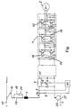
- the drawing shows a three-phase inverter 1 with an upstream brake actuator 11.
- a parallel capacitor 4 or backup capacitor is provided at the input of the brake actuator 11.
- the inverter 1, which feeds the asynchronous motor 2, consists of six transistors 12, each of which a freewheeling diode 13 is assigned in parallel. Each transistor 12 is connected to a control 14, the two controls 14 for the transistors 12 of one phase being connected to monitoring electronics 15. The currents and voltages in the feed lines to the asynchronous motor 2 are detected and fed to a control, not shown, which is also connected to the controls 14.
- the arrangement according to the invention is connected between a line choke 3 and a parallel capacitor 4.
- This consists of a freewheeling diode 5 in the reverse direction, which is connected to the DC voltage.
- An anti-parallel circuit consisting of a semiconductor switch 6, in this case a thyristor (GTO) which can be switched off, and a diode 7 is connected to the positive DC voltage line.
- the cathode of the freewheeling diode 5 is connected to the anode of the diode 7 and to the cathode of the thyristor 6 which can be switched off.
- Furthermore there are a current 8 and a Voltage measuring element 9 is provided which detects an input short circuit in which the thyristor 6 which can be switched off is blocked.
- a control 10 is provided for the thyristor 6 which can be switched off, to which the current 8 and the voltage measuring element 9 are connected and which blocks the thyristor 6 in the event of an irregular voltage drop and / or an increase in the feedback current I R to inadmissibly high values.
- the regenerative current I R always flows in the direction shown.
- the illustration shown in the figure is a drive for a rail vehicle, for example a tram.
- the line choke 3 is connected here with a connection via a current collector 16 and a switch 18 to the overhead line 17, which is the positive pole of the DC supply voltage.
- a second switch 19 with a charging resistor 20 is connected in series.
- the negative pole of the DC voltage is the rail 21 of the tram, which has earth potential, the connection with the brake actuator 11 and the inverter 1 being established via the wheels 22 of the rail vehicle.
- the semiconductor diodes of the brake actuator 11 are likewise not loaded with impermissibly high currents by the arrangement according to the invention in the event of a short circuit.
- the thyristor 6 that can be switched off is always conductive.
Landscapes
- Engineering & Computer Science (AREA)
- Power Engineering (AREA)
- Inverter Devices (AREA)
- Control Of Ac Motors In General (AREA)
- Control Of Electric Motors In General (AREA)
- Emergency Protection Circuit Devices (AREA)
- Control Of Motors That Do Not Use Commutators (AREA)
- Stopping Of Electric Motors (AREA)
Abstract
Description
Die Erfindung betrifft eine Anordnung bei einem Wechselrichter, vorzugsweise Pulswechselrichter, der eingangsseitig an einer Gleichspannung angeschlossen ist und einen Wechselstrommotor, insbesondere Asynchronmotor, speist, wobei die Anordnung zwischen einer Netzdrossel und einem Parallelkondensator am Eingang des Wechselrichters eingeschleift ist. Eine solche Anordnung ist aus der AT-A-329 659 bekannt.The invention relates to an arrangement in an inverter, preferably a pulse-controlled inverter, which is connected on the input side to a DC voltage and feeds an AC motor, in particular an asynchronous motor, the arrangement being looped in between a line reactor and a parallel capacitor at the input of the inverter. Such an arrangement is known from AT-A-329 659.
Bei Straßenbahnnetzen ist es üblich, diese in einzelne Versorgungsabschnitte zu unterteilen. Es kann somit vorkommen, daß eine Staßenbahngarnitur in einen kurzschlußbehafteten Streckenabschnitt einfährt, z.B. wird bei einem Unfall eines öffentlichen Verkehrsmittels der entsprechende Streckenabschnitt geerdet und es besteht die Möglichkeit, daß die nachfolgende Zugsgarnitur in den geerdeten Abschnitt einfährt. Im Bereich von Werkstätten und Wartungshallen werden zur Sicherheit oft einzelne Streckenabschnitte geerdet, wobei auch hier ein Einfahren in diesen Streckenabschnitt mit angelegtem Bügel nicht ausgeschlossen werden kann.
Ohne geeignete Maßnahmen würde in diesem Fehlerfall ein unzulässig hoher Rückspeisestrom (IR) fließen, der zur Zerstörung der Halbleiterventile des Wechselrichters führen würde.
Zur Beherrschung dieses Fehlers sind eine Reihe von Maßnahmen denkbar.
Eine wäre, einen mechanischen Schnellschalter am Eingang des Wechselrichters vorzusehen, der bei einem Überstrom den Wechselrichter vom Netz trennt. Da mechanische Schalter relativ große Auslösezeiten besitzen, können die Halbleiter nicht ausreichend gut geschützt werden. Eine andere Maßnahme bestünde darin, in den Leitungen zum Wechselrichter flinke Sicherungen vorzusehen. Durch diese Sicherungen wird zwar der Kurzschlußstrom begrenzt und der Wechselrichter vom fehlerbehafteten Netz getrennt, aber die Zugsgarnitur ist nach Behebung des Kurzschlusses aufgrund der defekten Sicherungen nicht mehr fahrbereit. Um eine Weiterfahrt zu ermöglichen, müssen die Sicherungen erst mühevoll ausgewechselt werden.With tram networks, it is common to divide them into individual supply sections. It can therefore happen that a tram set enters a short-circuit section, e.g. in the event of a public transport accident, the corresponding section is grounded and there is a possibility that the subsequent train set will enter the grounded section. In the area of workshops and maintenance halls, individual sections of the route are often grounded for safety, although entry into this section of the route with a bracket attached cannot be ruled out.
Without suitable measures, an inadmissibly high feedback current (I R ) would flow in this fault case, which would lead to the destruction of the semiconductor valves of the inverter.
A number of measures are conceivable to control this error.
One would be to provide a mechanical quick switch at the input of the inverter that disconnects the inverter from the grid in the event of an overcurrent. Since mechanical switches have relatively long tripping times, the semiconductors cannot be protected sufficiently well. Another measure would be to provide quick fuses in the lines to the inverter. These fuses limit the short-circuit current and separate the inverter from the faulty grid, but the train set is no longer operational after the short circuit has been remedied due to the defective fuses. In order to enable the journey to continue, the fuses must first be replaced with difficulty.
Die Aufgabe besteht nun darin, eine Anordnung zu schaffen, mit der Erd- bzw. Kurzschlüsse im speisenden Netz optimal beherrscht werden.The task now is to create an arrangement with which earth or short circuits in the supply network can be optimally controlled.
Diese Aufgabenstellung wird durch die Erfindung gelöst, welche dadurch gekennzeichnet ist, daß die Anordnung aus einer Freilaufdiode in Sperrichtung, welche an der Gleichspannung liegt, und einer Antiparallelschaltung aus einem Halbleiterschalter, insbesondere abschaltbarem Thyristor (GTO), und einer Diode, welche in die positive Gleichspannungsleitung geschaltet ist, wobei die Kathode der Freilaufdiode einerseits mit der Anode der Diode und andererseits mit dem Emitter bzw. der Kathode des Halbleiterschalters verbunden ist, besteht, und daß ein Strom- und ein Spannungsmeßorgan vorgesehen ist, welche einen Eingangskurzschluß erkennen, bei dem der Halbleiterschalter gesperrt wird.
Dadurch wird sichergestellt, daß keine zu hohen Ströme in den Halbleitern des Wechselrichters auftreten.
Im Fehlerfall wird der Halbleiterschalter gesperrt und die Freilaufdiode übernimmt den Netzstrom.
Die Diode der Antiparallelschaltung ist so angeordnet, daß bei Leistungsentnahme aus dem Gleichspannungsnetz diese Diode leitet. Hingegen fließt über den Halbleiterschalter nur dann Strom, wenn Energie ins Netz zurückgespeist wird.This object is achieved by the invention, which is characterized in that the arrangement of a freewheeling diode in the reverse direction, which is connected to the DC voltage, and an anti-parallel circuit consisting of a semiconductor switch, in particular a thyristor (GTO) that can be switched off, and a diode which is connected to the positive DC voltage line is connected, wherein the cathode of the freewheeling diode is connected on the one hand to the anode of the diode and on the other hand to the emitter or the cathode of the semiconductor switch, and that a current and a voltage measuring element is provided which recognize an input short circuit in which the Semiconductor switch is blocked.
This ensures that excessive currents do not occur in the semiconductors of the inverter.
In the event of a fault, the semiconductor switch is blocked and the freewheeling diode takes over the mains current.
The diode of the anti-parallel circuit is arranged so that this diode conducts when power is drawn from the DC voltage network. On the other hand, current only flows through the semiconductor switch when energy is fed back into the network.
Wird bei einem Netzkurzschluß der Wechselrichter nicht rasch vom Netz getrennt, so entlädt sich der Parallelbzw. Stützkondensator. Dies wirkt sich für den Wechselstrommotor wie ein Klemmenkurzschluß aus.If the inverter is not quickly disconnected from the grid in the event of a grid short circuit, the parallel or Backup capacitor. This affects the AC motor like a terminal short circuit.
Von Vorteil ist, daß eine Ansteuerung für den Halbleiterschalter vorgesehen ist, die bei einem irregulären Spannungseinbruch und/oder einem Anstieg des Rückspeisestromes auf unzulässig hohe Werte den Halbleiterschalter sperrt.It is advantageous that a control is provided for the semiconductor switch, which blocks the semiconductor switch in the event of an irregular voltage drop and / or an increase in the feedback current to impermissibly high values.
Die Erfindung wird nun an Hand der Zeichnung nun noch näher erläutert.The invention will now be explained in more detail with reference to the drawing.
Die Zeichnung zeigt einen dreiphasigen Wechselrichter 1 mit vorgeschaltetem Bremssteller 11. Am Eingang des Bremsstellers 11 ist ein Parallelkondensator 4 bzw. Stützkondensator vorgesehen.
Der Wechselrichter 1, welcher den Asynchronmotor 2 speist, besteht aus sechs Transistoren 12, denen je eine Freilaufdiode 13 parallel zugeordnet ist. Jeder Transistor 12 ist mit einer Ansteuerung 14 verbunden, wobei die beiden Ansteuerungen 14 für die Transistoren 12 einer Phase an eine Überwachungselektronik 15 angeschlossen sind. Die Ströme und Spannungen in den Zuleitungen zum Asynchronmotor 2 werden erfaßt und einer nicht dargestellten Steuerung zugeführt, welche auch mit den Ansteuerungen 14 verbunden ist.The drawing shows a three-phase inverter 1 with an
The inverter 1, which feeds the asynchronous motor 2, consists of six
Die erfindungsgemäße Anordnung ist zwischen einer Netzdrossel 3 und einem Parallelkondensator 4 geschaltet. Diese besteht aus einer Freilaufdiode 5 in Sperrichtung, welche an der Gleichspannung liegt. Eine Antiparallelschaltung aus einem Halbleiterschalter 6, in diesem Fall einem abschaltbaren Thyristor (GTO), und einer Diode 7 ist in die positive Gleichspannungsleitung geschaltet. Die Kathode der Freilaufdiode 5 ist mit der Anode der Diode 7 und mit der Kathode des abschaltbaren Thyristors 6 verbunden. Weiters sind ein Strom- 8 und ein Spannungsmeßorgan 9 vorgesehen, welche einen Eingangskurzschluß erkennen, bei dem der abschaltbare Thyristor 6 gesperrt wird.The arrangement according to the invention is connected between a
Für den abschaltbaren Thyristor 6 ist eine Ansteuerung 10 vorgesehen, an welche das Strom- 8 und das Spannungsmeßorgan 9 angeschlossen ist, und die bei einem irregulären Spannungseinbruch und/oder einem Anstieg des Rückspeisestromes IR auf unzulässig hohe Werte den Thyristor 6 sperrt. Der Rückspeisestrom IR fließt immer in der gezeichneten Richtung.A
Bei der in der Fig. gezeigten Darstellung handelt es sich um einen Antrieb für ein Schienenfahrzeug, z.B. eine Straßenbahn. Die Netzdrossel 3 ist hier mit einem Anschluß über einen Stromabnehmer 16 und einem Schalter 18 mit der Oberleitung 17, die der positive Pol der Versorgungsgleichspannung ist, verbunden. Parallel zu Schalter 18 ist ein zweiter Schalter 19 mit einem Ladewiderstand 20 in Serie geschaltet.
Der negative Pol der Gleichspannung ist die Schiene 21 der Straßenbahn, welche Erdpotential aufweist, wobei die Verbindung mit dem Bremssteller 11 und dem Wechselrichter 1 über die Räder 22 des Schienenfahrzeuges hergestellt ist.The illustration shown in the figure is a drive for a rail vehicle, for example a tram. The
The negative pole of the DC voltage is the
Bei einem Netzkurzschluß, welcher eine Verbindung zwischen der Oberleitung 17 und der Schiene 21 darstellt, würde ein unzulässig hoher Rückspeisestrom IR bzw. Kurzschlußstrom in der gezeichneten Richtung auftreten. Durch das Strom- 8 und das Spannungsmeßorgan 9 wird dieser Kurzschluß früh erkannt und der Thyristor 6 wird von der Ansteuerung 10 unverzüglich gesperrt, u.zw. bevor der Rückspeisestrom IR unzulässig hoch ansteigt und sich ein Kurzschluß des Asynchronmotors 2 über den Wechselrichter 1 einstellt. Der dabei in der Netzdrossel 3 eingeprägte Abschaltstrom geht auf die Freilaufdiode 5 über und nimmt infolge der ohmschen Kreiswiderstände kontinuierlich ab.In the event of a network short circuit, which represents a connection between the
Die Halbleiterdioden des Bremsstellers 11 werden ebenfalls durch die erfindungsgemäße Anordnung bei einem Kurzschluß nicht mit unzulässig hohen Strömen belastet.The semiconductor diodes of the
Im Normalbetrieb des Antriebes ist der abschaltbare Thyristor 6 immer leitend.In normal operation of the drive, the thyristor 6 that can be switched off is always conductive.
Claims (2)
- An arrangement in an inverter (1), preferably a pulse-width-modulated inverter, which is connected at its input end to a d.c. voltage and supplies an a.c. motor (2), in particular an asynchronous motor, wherein the arrangement is looped-in between a line reactor (3) and a parallel capacitor (4) at the input of the inverter (1),
characterised in that the arrangement consists of a freewheeling diode (5) in the blocking direction which is connected to the d.c. voltage, and an antiparallel circuit comprising a semiconductor switch (6), in particular a gate turn-off thyristor (GTO), and a diode (7) which is connected into the positive d.c. voltage line, wherein the cathode of the freewheeling diode (5) is connected on the one hand to the anode of the diode (7) and on the other hand to the emitter and cathode of the semiconductor switch (6), and that a current measuring element (8) and a voltage measuring element (9) are provided, which latter detect an input short-circuit in the case of which the semiconductor switch (6) is blocked. - An arrangement as claimed in Claim 1, characterised in that a drive means (10) is provided for the semiconductor switch (6), which drive means blocks the semiconductor switch (6) in the event of an irregular voltage break and/or an increase in the feedback current (IR) to impermissibly high values.
Applications Claiming Priority (3)
| Application Number | Priority Date | Filing Date | Title |
|---|---|---|---|
| AT2175/92 | 1992-11-04 | ||
| AT0217592A AT400991B (en) | 1992-11-04 | 1992-11-04 | DEVICE FOR PROTECTING AN INVERTER |
| PCT/AT1993/000170 WO1994010733A1 (en) | 1992-11-04 | 1993-11-04 | Device for protecting an inverter |
Publications (2)
| Publication Number | Publication Date |
|---|---|
| EP0667986A1 EP0667986A1 (en) | 1995-08-23 |
| EP0667986B1 true EP0667986B1 (en) | 1997-03-05 |
Family
ID=3529337
Family Applications (1)
| Application Number | Title | Priority Date | Filing Date |
|---|---|---|---|
| EP94900003A Expired - Lifetime EP0667986B1 (en) | 1992-11-04 | 1993-11-04 | Device for protecting an inverter |
Country Status (5)
| Country | Link |
|---|---|
| EP (1) | EP0667986B1 (en) |
| AT (2) | AT400991B (en) |
| DE (1) | DE59305661D1 (en) |
| GR (1) | GR3023388T3 (en) |
| WO (1) | WO1994010733A1 (en) |
Families Citing this family (1)
| Publication number | Priority date | Publication date | Assignee | Title |
|---|---|---|---|---|
| US3980010A (en) * | 1974-09-18 | 1976-09-14 | Luigi Collinucci | Cooking spit |
Family Cites Families (2)
| Publication number | Priority date | Publication date | Assignee | Title |
|---|---|---|---|---|
| DE2349161C3 (en) * | 1973-09-29 | 1978-09-21 | Brown, Boveri & Cie Ag, 6800 Mannheim | Arrangement for protecting a self-commutated inverter fed by a DC voltage intermediate circuit |
| DE4115856A1 (en) * | 1991-05-15 | 1992-11-19 | Abb Patent Gmbh | METHOD AND DEVICE FOR SWITCHING OFF OVERCURRENT IN A INVERTER |
-
1992
- 1992-11-04 AT AT0217592A patent/AT400991B/en not_active IP Right Cessation
-
1993
- 1993-11-04 AT AT94900003T patent/ATE149757T1/en active
- 1993-11-04 DE DE59305661T patent/DE59305661D1/en not_active Expired - Lifetime
- 1993-11-04 WO PCT/AT1993/000170 patent/WO1994010733A1/en active IP Right Grant
- 1993-11-04 EP EP94900003A patent/EP0667986B1/en not_active Expired - Lifetime
-
1997
- 1997-05-09 GR GR970401041T patent/GR3023388T3/en unknown
Also Published As
| Publication number | Publication date |
|---|---|
| EP0667986A1 (en) | 1995-08-23 |
| ATE149757T1 (en) | 1997-03-15 |
| AT400991B (en) | 1996-05-28 |
| ATA217592A (en) | 1995-09-15 |
| GR3023388T3 (en) | 1997-08-29 |
| DE59305661D1 (en) | 1997-04-10 |
| WO1994010733A1 (en) | 1994-05-11 |
Similar Documents
| Publication | Publication Date | Title |
|---|---|---|
| EP1917706B1 (en) | Rectifier circuit with distributed energy stores | |
| WO2010025758A1 (en) | Device having a converter | |
| EP0890220B1 (en) | Electronic branch switching device | |
| DE102012024728A1 (en) | Method and device for monitoring an electrical system for a return current | |
| DE112017000253T5 (en) | POWER CONVERSION DEVICE | |
| WO2019170475A1 (en) | Alternating-current charging device for a motor vehicle, and method for operating an alternating-current charging device for a motor vehicle | |
| WO2006021116A1 (en) | Device for feeding auxiliary operating devices for a fuel electric vehicle | |
| DE3032328A1 (en) | OVERCURRENT PROTECTION CIRCUIT | |
| EP0706218A2 (en) | Method to eliminate errors in a rectifying circuit device | |
| DE2223828C3 (en) | Overcurrent protection arrangement | |
| EP2220738B1 (en) | Drive system and associated control method | |
| EP0667986B1 (en) | Device for protecting an inverter | |
| DE10146868A1 (en) | Circuit arrangement for pre-charging capacitor supplied by current converter has semiconducting switch per current converter phase in series with phase-related converter diodes | |
| WO2020011331A1 (en) | Modular multilevel current converter with different sub-module types | |
| EP3656044A1 (en) | Converter assembly | |
| EP3652849B1 (en) | Coupling between circuits in drive networks | |
| DE19833490C2 (en) | DC link converter | |
| DE2831495A1 (en) | Overcurrent protection circuit for static inverter - has diode shunting transistor in series with input smoothing capacitor | |
| EP0332974A1 (en) | Short circuit protection for a pulse converter powered electric machine operated both motorically and generatingly | |
| DE19833551A1 (en) | Current supply system with DC link converter e.g. for locomotives and other rail-borne vehicles | |
| DE102022208424B3 (en) | Electrical circuit for interrupting a circuit and method for operating a high-voltage direct voltage network with the circuit | |
| DE4126816C2 (en) | Circuit arrangement for a rectifier substation | |
| EP0592696A1 (en) | Snubber circuit for an inverter branch | |
| DE2245090B2 (en) | ARRANGEMENT FOR CONNECTING AND DISCONNECTING AN AC SOURCE TO A CONSUMER | |
| DE4126818C2 (en) | Circuit arrangement for a rectifier substation |
Legal Events
| Date | Code | Title | Description |
|---|---|---|---|
| PUAI | Public reference made under article 153(3) epc to a published international application that has entered the european phase |
Free format text: ORIGINAL CODE: 0009012 |
|
| 17P | Request for examination filed |
Effective date: 19950420 |
|
| AK | Designated contracting states |
Kind code of ref document: A1 Designated state(s): AT BE CH DE DK ES FR GB GR IT LI NL SE |
|
| GRAG | Despatch of communication of intention to grant |
Free format text: ORIGINAL CODE: EPIDOS AGRA |
|
| 17Q | First examination report despatched |
Effective date: 19960131 |
|
| GRAH | Despatch of communication of intention to grant a patent |
Free format text: ORIGINAL CODE: EPIDOS IGRA |
|
| GRAH | Despatch of communication of intention to grant a patent |
Free format text: ORIGINAL CODE: EPIDOS IGRA |
|
| GRAA | (expected) grant |
Free format text: ORIGINAL CODE: 0009210 |
|
| AK | Designated contracting states |
Kind code of ref document: B1 Designated state(s): AT BE CH DE DK ES FR GB GR IT LI NL SE |
|
| PG25 | Lapsed in a contracting state [announced via postgrant information from national office to epo] |
Ref country code: NL Free format text: LAPSE BECAUSE OF FAILURE TO SUBMIT A TRANSLATION OF THE DESCRIPTION OR TO PAY THE FEE WITHIN THE PRESCRIBED TIME-LIMIT Effective date: 19970305 Ref country code: IT Free format text: LAPSE BECAUSE OF FAILURE TO SUBMIT A TRANSLATION OF THE DESCRIPTION OR TO PAY THE FEE WITHIN THE PRE;WARNING: LAPSES OF ITALIAN PATENTS WITH EFFECTIVE DATE BEFORE 2007 MAY HAVE OCCURRED AT ANY TIME BEFORE 2007. THE CORRECT EFFECTIVE DATE MAY BE DIFFERENT FROM THE ONE RECORDED.SCRIBED TIME-LIMIT Effective date: 19970305 Ref country code: ES Free format text: THE PATENT HAS BEEN ANNULLED BY A DECISION OF A NATIONAL AUTHORITY Effective date: 19970305 Ref country code: DK Effective date: 19970305 |
|
| REF | Corresponds to: |
Ref document number: 149757 Country of ref document: AT Date of ref document: 19970315 Kind code of ref document: T |
|
| REG | Reference to a national code |
Ref country code: CH Ref legal event code: EP |
|
| REF | Corresponds to: |
Ref document number: 59305661 Country of ref document: DE Date of ref document: 19970410 |
|
| GBT | Gb: translation of ep patent filed (gb section 77(6)(a)/1977) |
Effective date: 19970425 |
|
| PG25 | Lapsed in a contracting state [announced via postgrant information from national office to epo] |
Ref country code: SE Effective date: 19970605 |
|
| ET | Fr: translation filed | ||
| REG | Reference to a national code |
Ref country code: GR Ref legal event code: FG4A Free format text: 3023388 |
|
| NLV1 | Nl: lapsed or annulled due to failure to fulfill the requirements of art. 29p and 29m of the patents act | ||
| PLBE | No opposition filed within time limit |
Free format text: ORIGINAL CODE: 0009261 |
|
| STAA | Information on the status of an ep patent application or granted ep patent |
Free format text: STATUS: NO OPPOSITION FILED WITHIN TIME LIMIT |
|
| 26N | No opposition filed | ||
| REG | Reference to a national code |
Ref country code: GB Ref legal event code: IF02 |
|
| REG | Reference to a national code |
Ref country code: DE Ref legal event code: R081 Ref document number: 59305661 Country of ref document: DE Owner name: ELIN EBG TRACTION GMBH, AT Free format text: FORMER OWNER: ELIN ENERGIEANWENDUNG GES.M.B.H., WIEN, AT Effective date: 20111128 |
|
| REG | Reference to a national code |
Ref country code: AT Ref legal event code: PC Ref document number: 149757 Country of ref document: AT Kind code of ref document: T Owner name: SIEMENS AG OESTERREICH, AT Effective date: 20120419 |
|
| PGFP | Annual fee paid to national office [announced via postgrant information from national office to epo] |
Ref country code: GR Payment date: 20121112 Year of fee payment: 20 Ref country code: GB Payment date: 20121115 Year of fee payment: 20 |
|
| PGFP | Annual fee paid to national office [announced via postgrant information from national office to epo] |
Ref country code: FR Payment date: 20121214 Year of fee payment: 20 Ref country code: AT Payment date: 20121010 Year of fee payment: 20 |
|
| PGFP | Annual fee paid to national office [announced via postgrant information from national office to epo] |
Ref country code: BE Payment date: 20121217 Year of fee payment: 20 Ref country code: DE Payment date: 20130118 Year of fee payment: 20 Ref country code: CH Payment date: 20130211 Year of fee payment: 20 |
|
| REG | Reference to a national code |
Ref country code: DE Ref legal event code: R071 Ref document number: 59305661 Country of ref document: DE |
|
| REG | Reference to a national code |
Ref country code: DE Ref legal event code: R071 Ref document number: 59305661 Country of ref document: DE |
|
| REG | Reference to a national code |
Ref country code: CH Ref legal event code: PL |
|
| REG | Reference to a national code |
Ref country code: GB Ref legal event code: PE20 Expiry date: 20131103 |
|
| BE20 | Be: patent expired |
Owner name: *ELIN ENERGIEANWENDUNG G.M.B.H. Effective date: 20131104 |
|
| REG | Reference to a national code |
Ref country code: AT Ref legal event code: MK07 Ref document number: 149757 Country of ref document: AT Kind code of ref document: T Effective date: 20131104 |
|
| PG25 | Lapsed in a contracting state [announced via postgrant information from national office to epo] |
Ref country code: DE Free format text: LAPSE BECAUSE OF EXPIRATION OF PROTECTION Effective date: 20131105 Ref country code: GB Free format text: LAPSE BECAUSE OF EXPIRATION OF PROTECTION Effective date: 20131103 |
|
| REG | Reference to a national code |
Ref country code: GR Ref legal event code: MA Ref document number: 970401041 Country of ref document: GR Effective date: 20131105 |