EP0542349A1 - Controlling powershift transmissions - Google Patents
Controlling powershift transmissions Download PDFInfo
- Publication number
- EP0542349A1 EP0542349A1 EP92203398A EP92203398A EP0542349A1 EP 0542349 A1 EP0542349 A1 EP 0542349A1 EP 92203398 A EP92203398 A EP 92203398A EP 92203398 A EP92203398 A EP 92203398A EP 0542349 A1 EP0542349 A1 EP 0542349A1
- Authority
- EP
- European Patent Office
- Prior art keywords
- ratio
- change
- main clutch
- engaged
- clutch
- Prior art date
- Legal status (The legal status is an assumption and is not a legal conclusion. Google has not performed a legal analysis and makes no representation as to the accuracy of the status listed.)
- Granted
Links
Images
Classifications
-
- F—MECHANICAL ENGINEERING; LIGHTING; HEATING; WEAPONS; BLASTING
- F16—ENGINEERING ELEMENTS AND UNITS; GENERAL MEASURES FOR PRODUCING AND MAINTAINING EFFECTIVE FUNCTIONING OF MACHINES OR INSTALLATIONS; THERMAL INSULATION IN GENERAL
- F16H—GEARING
- F16H61/00—Control functions within control units of change-speed- or reversing-gearings for conveying rotary motion ; Control of exclusively fluid gearing, friction gearing, gearings with endless flexible members or other particular types of gearing
- F16H61/02—Control functions within control units of change-speed- or reversing-gearings for conveying rotary motion ; Control of exclusively fluid gearing, friction gearing, gearings with endless flexible members or other particular types of gearing characterised by the signals used
- F16H61/0202—Control functions within control units of change-speed- or reversing-gearings for conveying rotary motion ; Control of exclusively fluid gearing, friction gearing, gearings with endless flexible members or other particular types of gearing characterised by the signals used the signals being electric
- F16H61/0248—Control units where shifting is directly initiated by the driver, e.g. semi-automatic transmissions
-
- B—PERFORMING OPERATIONS; TRANSPORTING
- B60—VEHICLES IN GENERAL
- B60W—CONJOINT CONTROL OF VEHICLE SUB-UNITS OF DIFFERENT TYPE OR DIFFERENT FUNCTION; CONTROL SYSTEMS SPECIALLY ADAPTED FOR HYBRID VEHICLES; ROAD VEHICLE DRIVE CONTROL SYSTEMS FOR PURPOSES NOT RELATED TO THE CONTROL OF A PARTICULAR SUB-UNIT
- B60W10/00—Conjoint control of vehicle sub-units of different type or different function
- B60W10/02—Conjoint control of vehicle sub-units of different type or different function including control of driveline clutches
-
- B—PERFORMING OPERATIONS; TRANSPORTING
- B60—VEHICLES IN GENERAL
- B60W—CONJOINT CONTROL OF VEHICLE SUB-UNITS OF DIFFERENT TYPE OR DIFFERENT FUNCTION; CONTROL SYSTEMS SPECIALLY ADAPTED FOR HYBRID VEHICLES; ROAD VEHICLE DRIVE CONTROL SYSTEMS FOR PURPOSES NOT RELATED TO THE CONTROL OF A PARTICULAR SUB-UNIT
- B60W10/00—Conjoint control of vehicle sub-units of different type or different function
- B60W10/10—Conjoint control of vehicle sub-units of different type or different function including control of change-speed gearings
- B60W10/11—Stepped gearings
-
- B—PERFORMING OPERATIONS; TRANSPORTING
- B60—VEHICLES IN GENERAL
- B60W—CONJOINT CONTROL OF VEHICLE SUB-UNITS OF DIFFERENT TYPE OR DIFFERENT FUNCTION; CONTROL SYSTEMS SPECIALLY ADAPTED FOR HYBRID VEHICLES; ROAD VEHICLE DRIVE CONTROL SYSTEMS FOR PURPOSES NOT RELATED TO THE CONTROL OF A PARTICULAR SUB-UNIT
- B60W30/00—Purposes of road vehicle drive control systems not related to the control of a particular sub-unit, e.g. of systems using conjoint control of vehicle sub-units, or advanced driver assistance systems for ensuring comfort, stability and safety or drive control systems for propelling or retarding the vehicle
- B60W30/18—Propelling the vehicle
- B60W30/1819—Propulsion control with control means using analogue circuits, relays or mechanical links
-
- F—MECHANICAL ENGINEERING; LIGHTING; HEATING; WEAPONS; BLASTING
- F16—ENGINEERING ELEMENTS AND UNITS; GENERAL MEASURES FOR PRODUCING AND MAINTAINING EFFECTIVE FUNCTIONING OF MACHINES OR INSTALLATIONS; THERMAL INSULATION IN GENERAL
- F16H—GEARING
- F16H61/00—Control functions within control units of change-speed- or reversing-gearings for conveying rotary motion ; Control of exclusively fluid gearing, friction gearing, gearings with endless flexible members or other particular types of gearing
- F16H61/04—Smoothing ratio shift
- F16H2061/0444—Smoothing ratio shift during fast shifting over two gearsteps, e.g. jumping from fourth to second gear
- F16H2061/0448—Smoothing ratio shift during fast shifting over two gearsteps, e.g. jumping from fourth to second gear using a particular sequence of gear ratios or friction members
-
- F—MECHANICAL ENGINEERING; LIGHTING; HEATING; WEAPONS; BLASTING
- F16—ENGINEERING ELEMENTS AND UNITS; GENERAL MEASURES FOR PRODUCING AND MAINTAINING EFFECTIVE FUNCTIONING OF MACHINES OR INSTALLATIONS; THERMAL INSULATION IN GENERAL
- F16H—GEARING
- F16H59/00—Control inputs to control units of change-speed-, or reversing-gearings for conveying rotary motion
- F16H59/02—Selector apparatus
-
- F—MECHANICAL ENGINEERING; LIGHTING; HEATING; WEAPONS; BLASTING
- F16—ENGINEERING ELEMENTS AND UNITS; GENERAL MEASURES FOR PRODUCING AND MAINTAINING EFFECTIVE FUNCTIONING OF MACHINES OR INSTALLATIONS; THERMAL INSULATION IN GENERAL
- F16H—GEARING
- F16H59/00—Control inputs to control units of change-speed-, or reversing-gearings for conveying rotary motion
- F16H59/50—Inputs being a function of the status of the machine, e.g. position of doors or safety belts
- F16H59/56—Inputs being a function of the status of the machine, e.g. position of doors or safety belts dependent on signals from the main clutch
-
- F—MECHANICAL ENGINEERING; LIGHTING; HEATING; WEAPONS; BLASTING
- F16—ENGINEERING ELEMENTS AND UNITS; GENERAL MEASURES FOR PRODUCING AND MAINTAINING EFFECTIVE FUNCTIONING OF MACHINES OR INSTALLATIONS; THERMAL INSULATION IN GENERAL
- F16H—GEARING
- F16H63/00—Control outputs from the control unit to change-speed- or reversing-gearings for conveying rotary motion or to other devices than the final output mechanism
- F16H63/40—Control outputs from the control unit to change-speed- or reversing-gearings for conveying rotary motion or to other devices than the final output mechanism comprising signals other than signals for actuating the final output mechanisms
- F16H63/46—Signals to a clutch outside the gearbox
-
- Y—GENERAL TAGGING OF NEW TECHNOLOGICAL DEVELOPMENTS; GENERAL TAGGING OF CROSS-SECTIONAL TECHNOLOGIES SPANNING OVER SEVERAL SECTIONS OF THE IPC; TECHNICAL SUBJECTS COVERED BY FORMER USPC CROSS-REFERENCE ART COLLECTIONS [XRACs] AND DIGESTS
- Y10—TECHNICAL SUBJECTS COVERED BY FORMER USPC
- Y10T—TECHNICAL SUBJECTS COVERED BY FORMER US CLASSIFICATION
- Y10T74/00—Machine element or mechanism
- Y10T74/19—Gearing
- Y10T74/19219—Interchangeably locked
- Y10T74/19251—Control mechanism
- Y10T74/19256—Automatic
- Y10T74/1926—Speed responsive
Definitions
- This invention relates to the control of powershift transmissions for vehicles such as agricultural or industrial tractors.
- One object of the present invention is to provide a system for the control of the operative ratio of a multi-ratio vehicle powershift transmission which facilitates use of the vehicle by the operator.
- a system for controlling the selection of the operative ratio of a vehicle powershift transmission driven from an engine via a main clutch including a selector means for selecting the operative ratio of the transmission, characterised in that the system also includes a clutch status sensor for sensing engaged and disengaged conditions of the main clutch and control means including a ratio-change modulating function which, when the main clutch is engaged and a change is selected to a non-adjacent ratio, invokes a serial routine which ensures that each intermediate ratio between the current and selected ratios is momentarily engaged to ensure a smooth substantially jerk-free progression between the current and selected ratios, and when the main clutch is disengaged and a change is selected to a non-adjacent ratio, invokes a direct routine allowing a change from the current to the selected ratio without engagement of any intermediate ratio.
- a control system in accordance with the present invention greatly facilitates and speeds up the operation of the associated vehicle when it is desired to make changes to non-adjacent ratios in the powershift as, for example, when turning with a tractor on a field headland or when accelerating with a tractor pulling a heavy trailer on the road.
- the system may simply include a manually operable selector means, such as a column or floor mounted selector lever, with which the vehicle operator selects the desired operative ratio of the powershift.
- a manually operable selector means such as a column or floor mounted selector lever, with which the vehicle operator selects the desired operative ratio of the powershift.
- the system may be automatised with the operative ratio being selected automatically by the selector means which compares desired and actual values of one or more vehicle operating parameters and determines which ratio is the more efficient to select, consistent with the actual value of the sensed operating parameter(s) in order to try to achieve the desired value of the operating parameter(s).
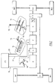
- this shows a tractor transmission in which an engine E drives front and rear wheels W1 and W2 via differentials D1 and D2, a main clutch C, a powershift unit P, a main gearbox G and a transfer box T.
- the main gearbox G will typically have four ratios and is controlled by a selector lever 10 moving in a generally H-shaped gate shown diagrammatically at 11.
- Main gearbox G also includes a high/low range facility indicated by the dotted detail H/L within the main gearbox G. This high/low range facility is actuated by movement of the selector lever 10 to the H/L position indicated at 12 on the gate 11.
- Each movement of the lever 10 to the position 12 operates a solenoid controlled fluid flow control valve (not shown) which in turn operates an hydraulic ram to successively switch the H/L facility between high and low ranges.
- the powershift transmission P is of a four ratio planetary type as described in the Applicant's co-pending UK Patent Applications Nos. 9116856.7 and 9116851.8 and provides four operating ranges A, B, C and D.
- the powershift transmission is controlled by a selector lever 15 which is movable between positions A, B, C and D in an associated range change selector gate 16.
- the actual engagement of the selected range A, B, C or D is effected by an hydraulic control system indicated diagrammatically at H in Figure 1.
- the main clutch C is operated by a clutch pedal 17.
- a sensor 18 is provided to indicate whether the clutch pedal is in the clutch engaged or clutch released position. This sensor may take any suitable form.
- An electronic microprocessor-based control system CS receives the signal from sensor 18 via line 19, together with a signal indicating the selected range A, B, C, or D via a line 20 and issues control signals to hydraulic control system H via a line or lines 21.
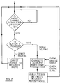
- the control system CS which may perform other control and monitoring functions (not described) in addition to the present ratio control function, operates in its ratio control function basically in accordance with the simple logic diagram of Figure 2.
- the powershift transmission cannot change to a non-adjacent range without each range between the current range and the selected range being at least momentarily engaged.
- the control system CS ensures, by the issuance of the appropriate signals to hydraulic control system H, that ranges C and B are each momentarily engaged so that the tractor will change progressively from range D to range C to range B to range A.
- This ensures an orderly and smooth change in the operating range of the transmission and is the "serial" range-changing routine described in detail in the Applicant's previously referred to co-pending application 9116851.8.
- This "serial" routine includes an inherent delay in changing between each adjacent range due to the predetermined sequence of events necessary to change the condition of the appropriate range engagement clutches of the powershift P and may also include a vehicle speed and engine RPM check between each range change to ensure a smooth transition between each range. Should the vehicle speed (detected by, for example, a radar device) be found inappropriate for the range and gearbox ratio selected, the range change may be barred and/or the tractor operator warned that the desired change has not been made. Similarly, if the engine RPM is found to be inappropriate this would be adjusted automatically before the engagement of the selected range is allowed.
- the ability to change directly to non-adjacent ratios greatly facilities and speeds up the operation of the vehicle in certain conditions.
- the arrangement of the ratios in the powershift transmission P and the main gearbox G may well necessitate a change to the entire powershift range band, i.e. from range A to range D, and then to shift simultaneously from the highest powershift range D to the lowest powershift range A whilst also changing to the next highest ratio in the main gearbox G in order to select the next highest ratio in the transmission as a whole.
- the present invention has been described above in relation to a tractor provided with a transmission in which the powershift ratios and main gearbox ratios are selected by manual operation of associated selector levers, the invention is also applicable to a transmission in which the powershift and/or main gearbox ratios are selected automatically by selector means which compares desired and actual values of one or more tractor operating parameters and then determines in accordance with predetermined operating criteria the transmission ratio to be selected consistent with the actual value of the sensed operating parameters in order to try to achieve the desired value of the operating parameters.
Abstract
Description
- This invention relates to the control of powershift transmissions for vehicles such as agricultural or industrial tractors.
- One object of the present invention is to provide a system for the control of the operative ratio of a multi-ratio vehicle powershift transmission which facilitates use of the vehicle by the operator.
- According to the present invention, there is provided a system for controlling the selection of the operative ratio of a vehicle powershift transmission driven from an engine via a main clutch, the system including a selector means for selecting the operative ratio of the transmission, characterised in that the system also includes a clutch status sensor for sensing engaged and disengaged conditions of the main clutch and control means including a ratio-change modulating function which, when the main clutch is engaged and a change is selected to a non-adjacent ratio, invokes a serial routine which ensures that each intermediate ratio between the current and selected ratios is momentarily engaged to ensure a smooth substantially jerk-free progression between the current and selected ratios, and when the main clutch is disengaged and a change is selected to a non-adjacent ratio, invokes a direct routine allowing a change from the current to the selected ratio without engagement of any intermediate ratio.
- A control system in accordance with the present invention greatly facilitates and speeds up the operation of the associated vehicle when it is desired to make changes to non-adjacent ratios in the powershift as, for example, when turning with a tractor on a field headland or when accelerating with a tractor pulling a heavy trailer on the road. In this latter situation, it may be necessary to change through the entire powershift ratio band and then shift simultaneously from the highest powershift ratio to the lowest powershift ratio whilst also changing to the next highest gear ratio in an associated main gearbox in order to select the next highest gear ratio in the transmission as a whole.
- The system may simply include a manually operable selector means, such as a column or floor mounted selector lever, with which the vehicle operator selects the desired operative ratio of the powershift.
- Alternatively, the system may be automatised with the operative ratio being selected automatically by the selector means which compares desired and actual values of one or more vehicle operating parameters and determines which ratio is the more efficient to select, consistent with the actual value of the sensed operating parameter(s) in order to try to achieve the desired value of the operating parameter(s).
- One embodiment of the present invention will now be described, by way of example only, with reference to the accompanying drawings in which:
- Figure 1 is a diagrammatic representation of a ratio selection system for use in an agricultural tractor, and
- Figure 2 is a flow diagram of the logic used in the system of Figure 1.
- Referring to Figure 1, this shows a tractor transmission in which an engine E drives front and rear wheels W1 and W2 via differentials D1 and D2, a main clutch C, a powershift unit P, a main gearbox G and a transfer box T. The main gearbox G will typically have four ratios and is controlled by a
selector lever 10 moving in a generally H-shaped gate shown diagrammatically at 11. Main gearbox G also includes a high/low range facility indicated by the dotted detail H/L within the main gearbox G. This high/low range facility is actuated by movement of theselector lever 10 to the H/L position indicated at 12 on thegate 11. Each movement of thelever 10 to theposition 12 operates a solenoid controlled fluid flow control valve (not shown) which in turn operates an hydraulic ram to successively switch the H/L facility between high and low ranges. - In the example illustrated, the powershift transmission P is of a four ratio planetary type as described in the Applicant's co-pending UK Patent Applications Nos. 9116856.7 and 9116851.8 and provides four operating ranges A, B, C and D. The powershift transmission is controlled by a
selector lever 15 which is movable between positions A, B, C and D in an associated rangechange selector gate 16. The actual engagement of the selected range A, B, C or D is effected by an hydraulic control system indicated diagrammatically at H in Figure 1. - Further details of a suitable hydraulic control system can be found in the Applicant's previously referred to co-pending application 9116851.8. Since the details of the hydraulic control system form no part of the present invention and are not necessary for a full understanding of the present invention, no further details will be given in the present application. The reader is directed to co-pending application 9116851.8 if further details of the hydraulic control system are required.
- The main clutch C is operated by a
clutch pedal 17. Asensor 18 is provided to indicate whether the clutch pedal is in the clutch engaged or clutch released position. This sensor may take any suitable form. - An electronic microprocessor-based control system CS receives the signal from
sensor 18 vialine 19, together with a signal indicating the selected range A, B, C, or D via aline 20 and issues control signals to hydraulic control system H via a line orlines 21. - The control system CS, which may perform other control and monitoring functions (not described) in addition to the present ratio control function, operates in its ratio control function basically in accordance with the simple logic diagram of Figure 2.
- Thus, whenever the
clutch pedal 17 is in the clutch engaged condition, the powershift transmission cannot change to a non-adjacent range without each range between the current range and the selected range being at least momentarily engaged. - For example, if the tractor operator were to select a change from current range D to range A by movement of
lever 15 from the D to A position, the control system CS ensures, by the issuance of the appropriate signals to hydraulic control system H, that ranges C and B are each momentarily engaged so that the tractor will change progressively from range D to range C to range B to range A. This ensures an orderly and smooth change in the operating range of the transmission and is the "serial" range-changing routine described in detail in the Applicant's previously referred to co-pending application 9116851.8. This "serial" routine includes an inherent delay in changing between each adjacent range due to the predetermined sequence of events necessary to change the condition of the appropriate range engagement clutches of the powershift P and may also include a vehicle speed and engine RPM check between each range change to ensure a smooth transition between each range. Should the vehicle speed (detected by, for example, a radar device) be found inappropriate for the range and gearbox ratio selected, the range change may be barred and/or the tractor operator warned that the desired change has not been made. Similarly, if the engine RPM is found to be inappropriate this would be adjusted automatically before the engagement of the selected range is allowed. - However, should the
clutch pedal 17 be depressed to disengage drive between the engine E and the powershift P, this clutch disengaged condition is communicated to the control system CS bysensor 18 and an alternative "direct" range-changing routine is invoked. - When operating under this "direct" routine, it is possible for the tractor operator to a select a change from range D to range A by movement of the
lever 15 from the D to A position without necessitating the engagement of the intermediate ratios C and B. - The "serial" and "direct" routines are clearly indicated in the logic diagram of Figure 2.
- As indicated above, the ability to change directly to non-adjacent ratios greatly facilities and speeds up the operation of the vehicle in certain conditions. For example, when the tractor is turning on a field headland or when the tractor is accelerating whilst pulling a heavy trailer on the road. In this latter situation the arrangement of the ratios in the powershift transmission P and the main gearbox G may well necessitate a change to the entire powershift range band, i.e. from range A to range D, and then to shift simultaneously from the highest powershift range D to the lowest powershift range A whilst also changing to the next highest ratio in the main gearbox G in order to select the next highest ratio in the transmission as a whole.
- Clearly a control system in accordance with the present invention will greatly facilitate such use since disengagement of the main clutch C will allow the operator to change between the powershift ratios A and D with very little time delay since there is no necessity to engage the intermediate ratios B and C.
- Whilst the present invention has been described above in relation to a tractor provided with a transmission in which the powershift ratios and main gearbox ratios are selected by manual operation of associated selector levers, the invention is also applicable to a transmission in which the powershift and/or main gearbox ratios are selected automatically by selector means which compares desired and actual values of one or more tractor operating parameters and then determines in accordance with predetermined operating criteria the transmission ratio to be selected consistent with the actual value of the sensed operating parameters in order to try to achieve the desired value of the operating parameters.
Claims (3)
- A system for controlling the selection of the operative ratio of a vehicle powershift transmission (P) driven from an engine (E) via a main clutch (C), the system including a selector means (15) for selecting the operative ratio of the transmission (P),
characterised in that the system also includes a clutch status sensor (18) for sensing engaged and disengaged conditions of the main clutch (C) and control means (CS) including a ratio-change modulating function which,
when the main clutch is engaged and a change is selected to a non-adjacent ratio, invokes a serial routine which ensures that each intermediate ratio between the current and selected ratios is momentarily engaged to ensure a smooth substantially jerk-free progression between the current and selected ratios, and
when the main clutch is disengaged and a change is selected to a non-adjacent ratio, invokes a direct routine allowing a change from the current to the selected ratio without engagement of any intermediate ratio. - A system according to Claim 1 characterised in that the selector means is a manually operable lever (15).
- A system according to Claim 1 characterised in that the selector means compares desired and actual values of one or more vehicle operating parameters and, in accordance with predetermined operating criteria, determines which transmission ratio to select consistent with the actual values of the vehicle operating parameters but such that the vehicle operating parameters tend towards their desired values.
Applications Claiming Priority (2)
| Application Number | Priority Date | Filing Date | Title |
|---|---|---|---|
| GB919123881A GB9123881D0 (en) | 1991-11-09 | 1991-11-09 | Controlling powershift transmissions |
| GB9123881 | 1991-11-09 |
Publications (2)
| Publication Number | Publication Date |
|---|---|
| EP0542349A1 true EP0542349A1 (en) | 1993-05-19 |
| EP0542349B1 EP0542349B1 (en) | 1998-01-14 |
Family
ID=10704399
Family Applications (1)
| Application Number | Title | Priority Date | Filing Date |
|---|---|---|---|
| EP92203398A Expired - Lifetime EP0542349B1 (en) | 1991-11-09 | 1992-11-05 | Controlling powershift transmissions |
Country Status (4)
| Country | Link |
|---|---|
| US (1) | US5277290A (en) |
| EP (1) | EP0542349B1 (en) |
| DE (1) | DE69224040T2 (en) |
| GB (2) | GB9123881D0 (en) |
Cited By (3)
| Publication number | Priority date | Publication date | Assignee | Title |
|---|---|---|---|---|
| FR2772859A1 (en) * | 1997-12-23 | 1999-06-25 | Luk Getriebe Systeme Gmbh | Transmission for vehicle |
| US5916291A (en) * | 1996-01-11 | 1999-06-29 | Case Corporation | Method and apparatus for shuttle shifting a power transmission |
| GB2371839A (en) * | 2001-02-01 | 2002-08-07 | Eaton Corp | Control for selecting automated transmission system shift strategy |
Families Citing this family (6)
| Publication number | Priority date | Publication date | Assignee | Title |
|---|---|---|---|---|
| DE4332265C1 (en) * | 1993-09-23 | 1995-05-04 | Daimler Benz Ag | Arrangement for controlling the gear change of an automatically shifting gear change transmission of a motor vehicle |
| US5505100A (en) * | 1994-09-29 | 1996-04-09 | Caterpillar Inc. | Method of controlling interrupted shifts for a powershift transmission |
| GB9505174D0 (en) * | 1995-03-15 | 1995-05-03 | Automotive Products Plc | Vehicle transmissions |
| JP3787959B2 (en) * | 1997-06-19 | 2006-06-21 | いすゞ自動車株式会社 | Clutch connection / disconnection device |
| EP0943844B1 (en) * | 1998-03-17 | 2003-08-06 | WABCO GmbH & CO. OHG | Method for controlling a transmission |
| US6151543A (en) * | 1999-01-14 | 2000-11-21 | Case Corporation | Method and apparatus for skip shifting in a power transmission |
Citations (6)
| Publication number | Priority date | Publication date | Assignee | Title |
|---|---|---|---|---|
| GB2119460A (en) * | 1982-04-23 | 1983-11-16 | Toyota Motor Co Ltd | Vehicle transmission system providing either manual or fully automatic operation |
| EP0108209A2 (en) * | 1982-10-09 | 1984-05-16 | WABCO Westinghouse Fahrzeugbremsen GmbH | Gear shifting for a power assisted transmission |
| US4640146A (en) * | 1983-04-25 | 1987-02-03 | Massey-Ferguson Inc. | Multiratio constant mesh change speed transmission |
| DE3610494A1 (en) * | 1986-03-27 | 1987-10-01 | Fendt & Co Xaver | Shift device for a multi-gear power-shift transmission of a commercial vehicle |
| US4855913A (en) * | 1987-05-29 | 1989-08-08 | J. I. Case Company | Electronic control system for powershift transmission |
| EP0404353A1 (en) * | 1989-06-19 | 1990-12-27 | Eaton Corporation | Semi-automatic shift implementation for mechanical transmission system |
Family Cites Families (8)
| Publication number | Priority date | Publication date | Assignee | Title |
|---|---|---|---|---|
| JPS53132659A (en) * | 1977-04-22 | 1978-11-18 | Toyota Motor Corp | Oil pressure control device of automatic transmission |
| JPS57146941A (en) * | 1981-03-06 | 1982-09-10 | Aisin Warner Ltd | Oil pressure controller for automatic speed changer |
| IT1151889B (en) * | 1982-06-28 | 1986-12-24 | Alfa Romeo Auto Spa | IGNITION CONTROL DEVICE FOR A C.I. ENGINE |
| GB8418749D0 (en) * | 1984-07-23 | 1984-08-30 | Eaton Ltd | Semi-automatic transmission control |
| US4722248A (en) * | 1986-04-11 | 1988-02-02 | Eaton Corporation | Transmission shift control system |
| GB8802284D0 (en) * | 1988-02-02 | 1988-03-02 | Eaton Corp | Method for smoothing skip up-shifts in automatic/semi-automatic mechanical transmission system |
| GB2228980A (en) * | 1989-03-06 | 1990-09-12 | Zahnradfabrik Friedrichshafen | Gearshift control with automatic control of clutch |
| US5054591A (en) * | 1990-10-11 | 1991-10-08 | Eaton Corporation | Transmission input section control |
-
1991
- 1991-11-09 GB GB919123881A patent/GB9123881D0/en active Pending
-
1992
- 1992-10-23 US US07/966,086 patent/US5277290A/en not_active Expired - Lifetime
- 1992-11-02 GB GB9222936A patent/GB2261924B/en not_active Expired - Lifetime
- 1992-11-05 EP EP92203398A patent/EP0542349B1/en not_active Expired - Lifetime
- 1992-11-05 DE DE69224040T patent/DE69224040T2/en not_active Expired - Lifetime
Patent Citations (6)
| Publication number | Priority date | Publication date | Assignee | Title |
|---|---|---|---|---|
| GB2119460A (en) * | 1982-04-23 | 1983-11-16 | Toyota Motor Co Ltd | Vehicle transmission system providing either manual or fully automatic operation |
| EP0108209A2 (en) * | 1982-10-09 | 1984-05-16 | WABCO Westinghouse Fahrzeugbremsen GmbH | Gear shifting for a power assisted transmission |
| US4640146A (en) * | 1983-04-25 | 1987-02-03 | Massey-Ferguson Inc. | Multiratio constant mesh change speed transmission |
| DE3610494A1 (en) * | 1986-03-27 | 1987-10-01 | Fendt & Co Xaver | Shift device for a multi-gear power-shift transmission of a commercial vehicle |
| US4855913A (en) * | 1987-05-29 | 1989-08-08 | J. I. Case Company | Electronic control system for powershift transmission |
| EP0404353A1 (en) * | 1989-06-19 | 1990-12-27 | Eaton Corporation | Semi-automatic shift implementation for mechanical transmission system |
Cited By (9)
| Publication number | Priority date | Publication date | Assignee | Title |
|---|---|---|---|---|
| US5916291A (en) * | 1996-01-11 | 1999-06-29 | Case Corporation | Method and apparatus for shuttle shifting a power transmission |
| FR2772859A1 (en) * | 1997-12-23 | 1999-06-25 | Luk Getriebe Systeme Gmbh | Transmission for vehicle |
| WO1999033682A3 (en) * | 1997-12-23 | 1999-10-07 | Luk Getriebe Systeme Gmbh | Gear box |
| FR2788321A1 (en) * | 1997-12-23 | 2000-07-13 | Luk Getriebe Systeme Gmbh | GEARBOX |
| GB2348255A (en) * | 1997-12-23 | 2000-09-27 | Luk Lamellen & Kupplungsbau | Gear box |
| GB2348255B (en) * | 1997-12-23 | 2002-07-03 | Luk Lamellen & Kupplungsbau | Gear box |
| US6591705B1 (en) | 1997-12-23 | 2003-07-15 | Luk Lamellen Und Kupplungsbau Beteiligungs Kg | Transmission |
| ES2222053A1 (en) * | 1997-12-23 | 2005-01-16 | Luk Lamellen Und Kupplungsbau Beteiligungs Kg. | Gear box |
| GB2371839A (en) * | 2001-02-01 | 2002-08-07 | Eaton Corp | Control for selecting automated transmission system shift strategy |
Also Published As
| Publication number | Publication date |
|---|---|
| GB9222936D0 (en) | 1992-12-16 |
| EP0542349B1 (en) | 1998-01-14 |
| DE69224040D1 (en) | 1998-02-19 |
| GB2261924A (en) | 1993-06-02 |
| GB2261924B (en) | 1995-09-20 |
| GB9123881D0 (en) | 1992-01-02 |
| US5277290A (en) | 1994-01-11 |
| DE69224040T2 (en) | 1998-05-14 |
Similar Documents
| Publication | Publication Date | Title |
|---|---|---|
| EP0316679B1 (en) | Vehicle drive line shift control system and method | |
| EP0352551B1 (en) | Upshift logic | |
| US5809441A (en) | Apparatus and method of neutral start control of a power transmission | |
| EP0651181B1 (en) | Driveline torque detection | |
| EP0578398B1 (en) | Shift control method/system | |
| EP0524767B1 (en) | Reengagement control/method for mechanical transmission system with automatic shift implementation | |
| US4852006A (en) | Amt off-highway downshift logic | |
| US5081588A (en) | Start from stop control method | |
| US5105357A (en) | Shift implementation control system and method for mechanical transmission system | |
| EP0473298B1 (en) | Control method inhibiting a change to neutral in a semi-automatic transmission | |
| US5611245A (en) | Method and apparatus for controlling a power transmission to match vehicle ground speed | |
| JPH0324356A (en) | Controller of semiautomatic speed changer and method of the same | |
| US5778330A (en) | Microprocessor controlled neutral circuit for a power transmission | |
| US6151543A (en) | Method and apparatus for skip shifting in a power transmission | |
| US5845224A (en) | Method and apparatus for preselecting gear ratios in a power transmission | |
| US5916291A (en) | Method and apparatus for shuttle shifting a power transmission | |
| EP0542349B1 (en) | Controlling powershift transmissions | |
| EP0431538B1 (en) | Manual override for automated mechanical transmission | |
| US5101943A (en) | Method of controlling inching clutches | |
| EP0576156B1 (en) | Enhanced semi-automated mechanical transmission system | |
| US5943912A (en) | Control for automated mechanical transmission system | |
| EP0697302B1 (en) | Downshift logic for semi-automatic mechanical transmission with manual clutch controller | |
| EP0565257A1 (en) | Enhanced semi-automated mechanical transmission system |
Legal Events
| Date | Code | Title | Description |
|---|---|---|---|
| PUAI | Public reference made under article 153(3) epc to a published international application that has entered the european phase |
Free format text: ORIGINAL CODE: 0009012 |
|
| AK | Designated contracting states |
Kind code of ref document: A1 Designated state(s): DE FR GB |
|
| 17P | Request for examination filed |
Effective date: 19931105 |
|
| 17Q | First examination report despatched |
Effective date: 19951121 |
|
| GRAG | Despatch of communication of intention to grant |
Free format text: ORIGINAL CODE: EPIDOS AGRA |
|
| GRAH | Despatch of communication of intention to grant a patent |
Free format text: ORIGINAL CODE: EPIDOS IGRA |
|
| GRAH | Despatch of communication of intention to grant a patent |
Free format text: ORIGINAL CODE: EPIDOS IGRA |
|
| GRAA | (expected) grant |
Free format text: ORIGINAL CODE: 0009210 |
|
| AK | Designated contracting states |
Kind code of ref document: B1 Designated state(s): DE FR GB |
|
| REF | Corresponds to: |
Ref document number: 69224040 Country of ref document: DE Date of ref document: 19980219 |
|
| ET | Fr: translation filed | ||
| PLBE | No opposition filed within time limit |
Free format text: ORIGINAL CODE: 0009261 |
|
| STAA | Information on the status of an ep patent application or granted ep patent |
Free format text: STATUS: NO OPPOSITION FILED WITHIN TIME LIMIT |
|
| 26N | No opposition filed | ||
| REG | Reference to a national code |
Ref country code: FR Ref legal event code: CD Ref country code: FR Ref legal event code: TP |
|
| REG | Reference to a national code |
Ref country code: GB Ref legal event code: IF02 |
|
| PGFP | Annual fee paid to national office [announced via postgrant information from national office to epo] |
Ref country code: GB Payment date: 20081022 Year of fee payment: 17 |
|
| GBPC | Gb: european patent ceased through non-payment of renewal fee |
Effective date: 20091105 |
|
| PG25 | Lapsed in a contracting state [announced via postgrant information from national office to epo] |
Ref country code: GB Free format text: LAPSE BECAUSE OF NON-PAYMENT OF DUE FEES Effective date: 20091105 |
|
| PGFP | Annual fee paid to national office [announced via postgrant information from national office to epo] |
Ref country code: DE Payment date: 20101119 Year of fee payment: 19 |
|
| PGFP | Annual fee paid to national office [announced via postgrant information from national office to epo] |
Ref country code: FR Payment date: 20111130 Year of fee payment: 20 |
|
| REG | Reference to a national code |
Ref country code: DE Ref legal event code: R071 Ref document number: 69224040 Country of ref document: DE |
|
| REG | Reference to a national code |
Ref country code: DE Ref legal event code: R071 Ref document number: 69224040 Country of ref document: DE |