EP0470064B1 - Internal combustion engine - Google Patents
Internal combustion engine Download PDFInfo
- Publication number
- EP0470064B1 EP0470064B1 EP91890146A EP91890146A EP0470064B1 EP 0470064 B1 EP0470064 B1 EP 0470064B1 EP 91890146 A EP91890146 A EP 91890146A EP 91890146 A EP91890146 A EP 91890146A EP 0470064 B1 EP0470064 B1 EP 0470064B1
- Authority
- EP
- European Patent Office
- Prior art keywords
- internal combustion
- combustion engine
- elements
- sound
- engine according
- Prior art date
- Legal status (The legal status is an assumption and is not a legal conclusion. Google has not performed a legal analysis and makes no representation as to the accuracy of the status listed.)
- Expired - Lifetime
Links
Images
Classifications
-
- F—MECHANICAL ENGINEERING; LIGHTING; HEATING; WEAPONS; BLASTING
- F16—ENGINEERING ELEMENTS AND UNITS; GENERAL MEASURES FOR PRODUCING AND MAINTAINING EFFECTIVE FUNCTIONING OF MACHINES OR INSTALLATIONS; THERMAL INSULATION IN GENERAL
- F16F—SPRINGS; SHOCK-ABSORBERS; MEANS FOR DAMPING VIBRATION
- F16F15/00—Suppression of vibrations in systems; Means or arrangements for avoiding or reducing out-of-balance forces, e.g. due to motion
- F16F15/02—Suppression of vibrations of non-rotating, e.g. reciprocating systems; Suppression of vibrations of rotating systems by use of members not moving with the rotating systems
-
- B—PERFORMING OPERATIONS; TRANSPORTING
- B60—VEHICLES IN GENERAL
- B60K—ARRANGEMENT OR MOUNTING OF PROPULSION UNITS OR OF TRANSMISSIONS IN VEHICLES; ARRANGEMENT OR MOUNTING OF PLURAL DIVERSE PRIME-MOVERS IN VEHICLES; AUXILIARY DRIVES FOR VEHICLES; INSTRUMENTATION OR DASHBOARDS FOR VEHICLES; ARRANGEMENTS IN CONNECTION WITH COOLING, AIR INTAKE, GAS EXHAUST OR FUEL SUPPLY OF PROPULSION UNITS IN VEHICLES
- B60K5/00—Arrangement or mounting of internal-combustion or jet-propulsion units
-
- F—MECHANICAL ENGINEERING; LIGHTING; HEATING; WEAPONS; BLASTING
- F16—ENGINEERING ELEMENTS AND UNITS; GENERAL MEASURES FOR PRODUCING AND MAINTAINING EFFECTIVE FUNCTIONING OF MACHINES OR INSTALLATIONS; THERMAL INSULATION IN GENERAL
- F16F—SPRINGS; SHOCK-ABSORBERS; MEANS FOR DAMPING VIBRATION
- F16F15/00—Suppression of vibrations in systems; Means or arrangements for avoiding or reducing out-of-balance forces, e.g. due to motion
- F16F15/005—Suppression of vibrations in systems; Means or arrangements for avoiding or reducing out-of-balance forces, e.g. due to motion using electro- or magnetostrictive actuation means
-
- B—PERFORMING OPERATIONS; TRANSPORTING
- B60—VEHICLES IN GENERAL
- B60G—VEHICLE SUSPENSION ARRANGEMENTS
- B60G2400/00—Indexing codes relating to detected, measured or calculated conditions or factors
- B60G2400/50—Pressure
-
- B—PERFORMING OPERATIONS; TRANSPORTING
- B60—VEHICLES IN GENERAL
- B60G—VEHICLE SUSPENSION ARRANGEMENTS
- B60G2400/00—Indexing codes relating to detected, measured or calculated conditions or factors
- B60G2400/90—Other conditions or factors
- B60G2400/91—Frequency
-
- B—PERFORMING OPERATIONS; TRANSPORTING
- B60—VEHICLES IN GENERAL
- B60G—VEHICLE SUSPENSION ARRANGEMENTS
- B60G2401/00—Indexing codes relating to the type of sensors based on the principle of their operation
- B60G2401/10—Piezoelectric elements
-
- B—PERFORMING OPERATIONS; TRANSPORTING
- B60—VEHICLES IN GENERAL
- B60K—ARRANGEMENT OR MOUNTING OF PROPULSION UNITS OR OF TRANSMISSIONS IN VEHICLES; ARRANGEMENT OR MOUNTING OF PLURAL DIVERSE PRIME-MOVERS IN VEHICLES; AUXILIARY DRIVES FOR VEHICLES; INSTRUMENTATION OR DASHBOARDS FOR VEHICLES; ARRANGEMENTS IN CONNECTION WITH COOLING, AIR INTAKE, GAS EXHAUST OR FUEL SUPPLY OF PROPULSION UNITS IN VEHICLES
- B60K5/00—Arrangement or mounting of internal-combustion or jet-propulsion units
- B60K5/12—Arrangement of engine supports
- B60K5/1283—Adjustable supports, e.g. the mounting or the characteristics being adjustable
Definitions
- the invention relates to an internal combustion engine with a sound-conducting inner structure, consisting essentially of a cylinder block, cylinder head and crankshaft bearing, which is supported by brackets with devices for noise reduction, the internal combustion engine having a preferably closed, sound-absorbing outer structure, which with the inner structure via at least three of each a device for noise reduction mounts is connected.
- Devices for active noise reduction have been known for a long time. Such systems are successfully used above all to reduce airborne noise in pipes and lines, e.g. in air conditioning ducts, incinerators and exhaust systems.
- the primary sound to be reduced is superimposed with the help of a loudspeaker with an equally large and 180 ° phase-shifted "anti-sound", which counteracts the primary sound and compensates it by destructive interference.
- a signal is obtained either with a microphone or directly from the primary sound source, from which a regulating or control unit generates the signal for controlling the loudspeaker.
- the low-frequency vibrations stem from the 2nd order mass forces. They are between 20 and 200 Hz. These can be compensated with a second-order mass balance, which, however, requires a great deal of effort. In internal combustion engines without this mass balance, these vibrations, which are unpleasant for the vehicle, can be reduced with complex engine mountings or brackets for the internal structure.
- Such mounts with devices for active noise reduction in connection with internal combustion engines have become known, for example, from DE-OS 34 19 437 on which this invention is based.
- the device referred to here as a hydraulically damped engine mount has two chambers, which are separated by an intermediate plate with a throttle point and filled with a hydraulic fluid, the motor-side chamber having an active vibration exciter (actuator) which can be controlled as a function of predefinable operating parameters.
- This vibration exciter which can work pneumatically, hydraulically or electrodynamically, can be used to generate vibrations in opposite phase to those in the holder, which prevents the transmission of structure-borne noise.
- the radiated airborne sound cannot be influenced with this device.
- EP-A3 0 347 666 shows an active vibration-damping and vibration-compensating bearing arrangement for internal combustion engines with a piezoelectric actuator element and hydraulic pressure chambers.
- an actuator column having the piezoceramic elements is designed in a pot-shaped manner Abutment arranged.
- the actuator column is surrounded by a tubular spring which supports the actuator column at one end against the abutment and at the other end engages a membrane which is movable in the direction of the motor longitudinal axis.
- the thickness of the piezoceramic elements is changed by control signals, which causes an axial movement of the actuator column which is transmitted to the membrane.
- the movement of the diaphragm is transmitted to the engine block via a liquid-filled working space and a spring element on a stud bolt arranged in the longitudinal axis of the engine bearing.
- the airborne noise emitted cannot be influenced.
- JP-A 63-203941 shows a device for active noise reduction, consisting of an actuator and a sensor element.
- a piezoelectric bimorph which is clamped in a housing and consists of bending-sensitive piezoelectric plates, is bent by a rod-shaped contact element in a direction normal to the plates. The deflection is determined by the sensor electrode, whereupon the longitudinal (one-dimensional) vibration is damped by the actuator element.
- This one-dimensional device which does not influence the emitted airborne sound, is only possible with considerably great effort in multidimensional systems, such as internal combustion engines.
- the object of the invention is to further develop an internal combustion engine of the type mentioned at the outset such that the sound-conducting inner structure is largely decoupled in terms of vibration from the engine mount or from the vehicle, the radiated airborne sound also being to be minimized.
- each device is provided for active noise reduction and has at least one sensor element for detecting structure-borne sound vibrations and at least one actuator element for generating antiphase structure-borne sound vibrations, an electronic regulating and control device being provided via which the actuator elements with the sensor elements are connected, and that in each case one articulation point of each holder is articulated on the inner or outer structure.
- the basic idea of such an actively noise-reduced internal combustion engine is that the force-carrying inner structure is connected to the outer structure by only a few connecting elements, so that only a few defined structure-borne sound vibration modes are permitted, the transmission of which via the holding elements acting as sound waveguides is prevented by suitable devices.
- the sound to be reduced is channeled, so to speak, so that the principle of active noise reduction can be applied to each quasi-one-dimensional sound transmission channel. Airborne noise is effectively reduced by the sound-absorbing outer structure.
- each articulation point of each holder is designed as a ball joint.
- the sensor element and the actuator element each consist of at least one piezoelectric element, the electrode surfaces of which are connected via at least one control channel of the regulating and control device, or that at least two piezoelectric elements are combined via a biasing element, each piezoelectric Element has at least three areas provided with electrodes and the mutually assigned areas of two piezoelectric elements are each connected via a control channel of the regulating and control device and form a pair of actuator and sensor element.
- devices for impedance matching of the device for reducing noise to the vibrating system may be required.
- Suitable transformers can, however, deliver the power applied in the required ratio of sound power to sound speed.
- the sensor element and the actuator element each consist of a disk-shaped piezoelectric element, which elements are separated by a central electrode plate between two membranes, that connectable housing parts of the device for noise reduction adjoin both membranes, of which at least one housing part unites pressure chamber sealed off from the adjacent membrane for receiving a hydraulic fluid has, the pressure chamber being connected to a piston chamber, the piston of which is loaded by a spring element is connected to a strut leading to an articulation point.
- the at least one pressure chamber has a hydraulic connection, via which pressure waves which can be tapped at the internal combustion engine and are phase-shifted to vibrations caused by inertia forces can be introduced into the pressure chamber.
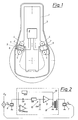
- the sound-conducting inner structure 1 of an internal combustion engine consisting essentially of a cylinder block, cylinder head and crankshaft bearing, is connected to a sound-absorbing outer structure 3 at at least three (two shown) points using brackets 2.
- the brackets 2 are attached to articulation points 4 both on the inner structure 1 and on the sound-absorbing outer structure 3.
- a device 5, which brings about active noise reduction, is located between the two articulation points 4.
- the articulation points 4 are located at points with high mechanical rigidity (impedance), so that only small movement amplitudes occur.
- FIG. 2 shows an example of a simple embodiment of the regulating and control electronics 8 (FIG. 1) belonging to each pair of sensor 6 and actuator 7.
- the charge signal 7 coming from the piezoelectric sensor 6 is preamplified in a charge amplifier stage 9, a passive low-pass filter 10 and a power amplifier (booster) 11 and via a transformer 12 for electrical impedance matching to the piezoelectric actuator 7 created.
- An ohmic feedback 13 stabilizes the DC operating point and limits the effective frequency range at low frequencies. Since actuator 7 and sensor 6 are practically at the same location, the force F N coming from the motor is ideally compensated for by the force F A generated by the actuator. Forces F E not compensated are detected and processed by sensor 6.
- FIG. 3 shows the idealized frequency response of the control electronics according to FIG. 2.
- the ratio of the generated sound force F A at the actuator to the registered sound force F E at the sensor is plotted on a double logarithmic scale over the frequency F.
- This characteristic curve also represents the controller characteristic.
- the design must be such that no mechanical resonances can be excited in the frequency band of the control, i.e. the anchors and brackets must be stiff and light in relation to the stimulable structure-borne vibration modes.
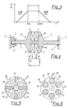
- Fig. 4 shows a bracket 2, in which the articulation point 4 e.g. rigid on the inner structure 1 and the other articulation point 4 articulated on the outer structure 3, e.g. is designed as a ball joint 14, so that only the longitudinal forces and the two bending moments can be transmitted. Pairs of adjacent piezoelectric actuators 7 and sensors 6, which are each connected via a control channel 16 of the regulating and control device 8, serve as active elements. The piezoelectric elements 15 are combined via a biasing element 17.
- each piezoelectric element 15 has four areas provided with electrodes 18, areas of two mutually superposed elements 15 each forming a pair of actuator and sensor elements and via a channel 16 of the control element. and control device 8.
- a plurality of units 19 composed of actuator and sensor elements (for example one sensor element, several actuator elements) can also be arranged in a plane 21 normal to the longitudinal axis 20 of the holder, the sensor elements 6 and actuator elements 7 consisting of separate (in FIG. 6 stacked) piezoelectric elements 15 'exist.
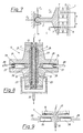
- both the sensor element 6 and the actuator element 7 each consist of a large-area piezoelectric element 15. Both elements are clamped separately between two membranes 23 by an electrode plate 22. Connected to both membranes 23 are interconnectable housing parts 24 of the device 5, which have pressure spaces 25 sealed off from the adjacent membranes for receiving a hydraulic fluid. Each pressure chamber 25 is connected to a piston chamber 26, whose piston 28, which is loaded by a spring element 27, is connected to a strut 29 leading to a pivot point is.
- the travel of the piezoelectric elements 15 is transformed up here via the ratio of the piston area to the area of the piezoelectric elements in order to achieve a sufficiently large piston stroke. It is also possible to design the device asymmetrically and to provide only one pressure chamber 25 and one piston system.
- the or both pressure chambers 25 can have a hydraulic connection 30, via which pressure waves can be introduced into the pressure chamber 25. These can, for example, be out of phase with vibrations caused by 2nd order mass forces of the internal combustion engine. This is then a controlled active element that can be implemented very efficiently in terms of energy, so that only little energy is required for the remaining noise reduction by the controlled piezoelectric element.
- FIG. 9 Another embodiment of the same principle is shown in FIG. 9, in which both pistons 28 are arranged parallel to the piezoelectric elements 15 in a space-saving manner.
Abstract
Description
Die Erfindung betrifft eine Brennkraftmaschine mit einer schallführenden Innenstruktur, im wesentlichen bestehend aus Zylinderblock, Zylinderkopf und Kurbelwellenlager, welche über Halterungen mit Einrichtungen zur Geräuschminderung abgestützt ist, wobei die Brennkraftmaschine eine Vorzugsweise geschlossene, schalldämmende Außenstruktur aufweist, welche mit der Innenstruktur über zumindest drei der jeweils eine Einrichtung zur Schallminderung aufweisenden Halterungen verbunden ist.The invention relates to an internal combustion engine with a sound-conducting inner structure, consisting essentially of a cylinder block, cylinder head and crankshaft bearing, which is supported by brackets with devices for noise reduction, the internal combustion engine having a preferably closed, sound-absorbing outer structure, which with the inner structure via at least three of each a device for noise reduction mounts is connected.
Aus der DE-OS 28 48 860 ist eine Brennkraftmaschine nach dem Oberbegriff des Anspruchs 1 bekannt, bei welcher die Einrichtung zur Schallminderung aus passiven Elementen besteht, die die Körperschallübertragung nur unbefriedigend vermindern können.From DE-OS 28 48 860 an internal combustion engine according to the preamble of claim 1 is known, in which the device for sound reduction consists of passive elements that can reduce the structure-borne noise transmission only unsatisfactorily.
Einrichtungen zur aktiven Geräuschminderung sind seit längerem bekannt. Mit Erfolg verwendet werden solche Systeme vor allem bei der Minderung von Luftschall in Rohren und Leitungen, z.B. in Klimaschächten, Verbrennungsanlagen und Auspuffanlagen. Im einfachen Fall wird dabei dem zu mindernden Primärschall mit Hilfe eines Lautsprechers ein gleich großer und um 180° phasenverschobener "Anti-Schall" überlagert, der dem Primärschall entgegenwirkt und ihn durch destruktive Interferenz gerade kompensiert. Dabei wird entweder mit einem Mikrophon oder direkt von der Primärschallquelle ein Signal gewonnen, aus dem eine Regel- bzw. Steuereinheit das Signal zur Ansteuerung des Lautsprechers erzeugt.Devices for active noise reduction have been known for a long time. Such systems are successfully used above all to reduce airborne noise in pipes and lines, e.g. in air conditioning ducts, incinerators and exhaust systems. In a simple case, the primary sound to be reduced is superimposed with the help of a loudspeaker with an equally large and 180 ° phase-shifted "anti-sound", which counteracts the primary sound and compensates it by destructive interference. A signal is obtained either with a microphone or directly from the primary sound source, from which a regulating or control unit generates the signal for controlling the loudspeaker.
Dieser einfachste Fall ist aber nur in eindimensionalen, quasi unendlich ausgedehnten und daher reflexionsfreien Systemen gegeben. Bei realen Systemen muß durch geeignete, meist nur empirisch ableitbare Maßnahmen erreicht werden, daß einerseits die Geräuschminderung im gesamten maßgeblichen Ortsbereich gewährleistet ist, und daß andererseits keine Selbsterregung des Systems zu Eigenschwingungen stattfindet. Für mehrdimensionale Systeme mit reflektierenden Strukturen und Begrenzungen sind solche Maßnahmen häufig unmöglich oder mit enormem Aufwand an Sensorik, Aktorik und vor allem mit komplizierter Signalverarbeitung und Regelungstechnik verbunden.This simplest case is only given in one-dimensional, quasi infinitely extended and therefore reflection-free systems. In real systems, suitable measures, which can usually only be derived empirically, must ensure that noise reduction is ensured in the entire relevant local area on the one hand and that the system does not self-excite to self-oscillations on the other hand. For multi-dimensional systems with reflective structures and boundaries such measures are often impossible or involve an enormous amount of sensor, actuator and, above all, complicated signal processing and control technology.
Die geschilderte Situation scheint die Nutzung der aktiven Geräuschminderung bei Brennkraftmaschinen zu verhindern.The situation described seems to prevent the use of active noise reduction in internal combustion engines.
Im praktischen Motorbetrieb fallen vor allem zwei Schwingungsverhalten auf, die für den abgestrahlten Luftschall und die Motorvibrationen sowie die Fahrzeuganregungen infolge der Motorvibrationen maßgebend sind, nämlich das tieffrequente und das hochfrequente Schwingungsverhalten. Die tieffrequenten Schwingungen rühren beispielsweise bei einem 4-Zylinder Reihenmotor von den Massenkräften 2. Ordnung her. Sie liegen zwischen 20 und 200 Hz. Diese können mit einem Massenausgleich 2. Ordnung ausgeglichen werden, welcher jedoch einen großen Aufwand erfordert. Bei Brennkraftmaschinen ohne diesen Massenausgleich können diese für das Fahrzeug unangenehmen Schwingungsanregungen mit aufwendigen Motoraufhängungen bzw. Halterungen für die Innenstruktur verringert werden.In practical engine operation, two vibration characteristics are particularly noticeable, which are decisive for the airborne noise emitted and the engine vibrations as well as the vehicle excitations as a result of the engine vibrations, namely the low-frequency and the high-frequency vibration behavior. In a 4-cylinder in-line engine, for example, the low-frequency vibrations stem from the 2nd order mass forces. They are between 20 and 200 Hz. These can be compensated with a second-order mass balance, which, however, requires a great deal of effort. In internal combustion engines without this mass balance, these vibrations, which are unpleasant for the vehicle, can be reduced with complex engine mountings or brackets for the internal structure.
Derartige Halterungen mit Einrichtungen zur aktiven Geräuschminderung im Zusammenhang mit Brennkraftmaschinen sind beispielsweise aus der dieser Erfindung zugrundeliegenden DE-OS 34 19 437 bekanntgeworden. Die hier als hydraulisch gedämpftes Motorlager bezeichnete Einrichtung weist zwei durch eine Zwischenplatte mit Drosselstelle getrennte, mit einer hydraulischen Flüssigkeit gefüllte Kammern auf, wobei die motorseitige Kammer einen aktiven, in Abhängigkeit von vorgebbaren Betriebsparametern steuerbaren Schwingungserreger (Aktor) aufweist. Mit diesem Schwingungserreger, der pneumatisch, hydraulisch oder elektrodynamisch arbeiten kann, können gezielt Schwingungen in Gegenphase zu jenen in der Halterung erzeugt werden, wodurch die Weiterleitung des Körperschalls unterbunden wird. Nachteiligerweise kann mit dieser Einrichtung jedoch der abgestrahlte Luftschall nicht beeinflußt werden.Such mounts with devices for active noise reduction in connection with internal combustion engines have become known, for example, from DE-OS 34 19 437 on which this invention is based. The device referred to here as a hydraulically damped engine mount has two chambers, which are separated by an intermediate plate with a throttle point and filled with a hydraulic fluid, the motor-side chamber having an active vibration exciter (actuator) which can be controlled as a function of predefinable operating parameters. This vibration exciter, which can work pneumatically, hydraulically or electrodynamically, can be used to generate vibrations in opposite phase to those in the holder, which prevents the transmission of structure-borne noise. Disadvantageously, however, the radiated airborne sound cannot be influenced with this device.
Weiters zeigt die EP-A3 0 347 666 eine aktive schwingungsdämpfende und schwingungskompensierende Lageranordnung für Brennkraftmaschinen mit einem piezoelektrischen Aktorelement und Hydraulikdruckräumen. Dabei ist eine die piezokeramischen Elemente aufweisende Aktuatorsäule in einem topfförmig gestalteten Widerlager angeordnet. Die Aktuatorsäule ist von einer Rohrfeder umgeben, welche die Aktuatorsäule an einem Ende gegen das Widerlager abstützt und am anderen Ende an einer in Richtung der Motorlängsachse beweglichen Membran angreift. Durch Steuersignale werden die piezokeramischen Elemente in ihrer Dicke verändert, was eine auf die Membran übertragene Axialbewegung der Aktuatorsäule verursacht. Die Bewegung der Membran wird über einen flüssigkeitsgefüllten Arbeitsraum und ein Federelement auf einen in Motorlagerlängsachse angeordneten Stehbolzen auf den Motorblock übertragen. Auch hier kann der abgestrahlte Luftschall nicht beeinflußt werden.Furthermore, EP-A3 0 347 666 shows an active vibration-damping and vibration-compensating bearing arrangement for internal combustion engines with a piezoelectric actuator element and hydraulic pressure chambers. Here, an actuator column having the piezoceramic elements is designed in a pot-shaped manner Abutment arranged. The actuator column is surrounded by a tubular spring which supports the actuator column at one end against the abutment and at the other end engages a membrane which is movable in the direction of the motor longitudinal axis. The thickness of the piezoceramic elements is changed by control signals, which causes an axial movement of the actuator column which is transmitted to the membrane. The movement of the diaphragm is transmitted to the engine block via a liquid-filled working space and a spring element on a stud bolt arranged in the longitudinal axis of the engine bearing. Here, too, the airborne noise emitted cannot be influenced.
In der JP-A 63-203941 wird eine Einrichtung zur aktiven Schallminderung, bestehend aus einem Aktor- und einem Sensorelement gezeigt. Dabei wird ein in ein Gehäuse eingespannter piezoelektrischer Bimorph, bestehend aus biegesensitiven, piezoelektrischen Platten, durch ein stangenförmiges Kontaktglied in einer normal zu den Platten stehenden Richtung verbogen. Die Auslenkung wird durch die Sensorelektrode festgestellt, worauf über das Aktorelement die longitudinale (eindimensionale) Schwingung gedämpft wird. Der Einsatz dieser eindimensional wirkenden, den abgestrahlten Luftschall nicht beeinflussenden Vorrichtung ist bei mehrdimensionalen Systemen, wie Brennkraftmaschinen, nur mit erheblich großem Aufwand möglich.JP-A 63-203941 shows a device for active noise reduction, consisting of an actuator and a sensor element. In this case, a piezoelectric bimorph, which is clamped in a housing and consists of bending-sensitive piezoelectric plates, is bent by a rod-shaped contact element in a direction normal to the plates. The deflection is determined by the sensor electrode, whereupon the longitudinal (one-dimensional) vibration is damped by the actuator element. The use of this one-dimensional device, which does not influence the emitted airborne sound, is only possible with considerably great effort in multidimensional systems, such as internal combustion engines.
Weiters ist aus der US-PS 4 600 863 eine ähnliche Einrichtung bekannt geworden, bei welcher eine Halterung über ein Sensorelement und ein Aktorelement verfügt, welche über einen Regelkreis in Verbindung stehen. Weiters weist diese Halterung ein Element auf, über welches nur parallel zur Längsachse der Halterung wirkende Kräfte übertragen werden können. Die genannte Einrichtung verwendet sowohl mechanische als auch magnetostriktive Aktoren. Im Hinblick auf die Ausbreitung von Luftschall kann jedoch auch diese Einrichtung nicht geräuschmindernd eingesetzt werden.Furthermore, a similar device has become known from US Pat. No. 4,600,863, in which a holder has a sensor element and an actuator element, which are connected via a control circuit. Furthermore, this holder has an element by means of which forces acting only parallel to the longitudinal axis of the holder can be transmitted. The device mentioned uses both mechanical and magnetostrictive actuators. With regard to the propagation of airborne noise, however, this device cannot be used to reduce noise.
Aufgabe der Erfindung ist es, eine Brennkraftmaschine der eingangs genannten Art derart weiterzubilden, daß die schallführende Innenstruktur schwingungsmäßig weitgehend vom Motorlager bzw. vom Fahrzeug abgekoppelt ist, wobei auch der abgestrahlte Luftschall minimiert werden soll.The object of the invention is to further develop an internal combustion engine of the type mentioned at the outset such that the sound-conducting inner structure is largely decoupled in terms of vibration from the engine mount or from the vehicle, the radiated airborne sound also being to be minimized.
Erfindungsgemäß wird diese Aufgabe dadurch gelöst, daß jede Einrichtung zur aktiven Schallminderung vorgesehen ist und zumindest ein Sensorelement zur Erfassung von Körperschallschwingungen sowie zumindest ein Aktorelement zur Erzeugung gegenphasiger Körperschallschwingungen aufweist, wobei eine elektronische Regel- und Steuereinrichtung vorgesehen ist, über welche die Aktorelemente mit den Sensorelementen in Verbindung stehen, und daß jeweils ein Anlenkpunkt jeder Halterung an der Innen- oder Außenstruktur gelenkig ausgeführt ist. Die Grundidee einer solchen aktiv geräuschgeminderten Brennkraftmaschine besteht darin, daß die kraftführende Innenstruktur durch nur wenige Verbindungselemente mit der Außenstruktur verbunden wird, sodaß nur wenige, definierte Körperschallschwingungsmoden zugelassen werden, deren Übertragung über die als Schallwellenleiter wirkenden Halteorgane durch geeignete Vorrichtungen gehindert wird. Der zu mindernde Schall wird sozusagen kanalisiert, wodurch auf jeden einzelnen quasi eindimensionalen Schallübertragungskanal das Prinzip der aktiven Geräuschminderung angewandt werden kann. Der Luftschall wird durch die schalldämmende Außenstruktur wirksam vermindert.According to the invention, this object is achieved in that each device is provided for active noise reduction and has at least one sensor element for detecting structure-borne sound vibrations and at least one actuator element for generating antiphase structure-borne sound vibrations, an electronic regulating and control device being provided via which the actuator elements with the sensor elements are connected, and that in each case one articulation point of each holder is articulated on the inner or outer structure. The basic idea of such an actively noise-reduced internal combustion engine is that the force-carrying inner structure is connected to the outer structure by only a few connecting elements, so that only a few defined structure-borne sound vibration modes are permitted, the transmission of which via the holding elements acting as sound waveguides is prevented by suitable devices. The sound to be reduced is channeled, so to speak, so that the principle of active noise reduction can be applied to each quasi-one-dimensional sound transmission channel. Airborne noise is effectively reduced by the sound-absorbing outer structure.
In einer Weiterbildung der Erfindung ist vorgesehen, daß jeweils ein Anlenkpunkt jeder Halterung als Kugelgelenk ausgeführt ist. Dadurch kann die Anzahl jener Körperschallschwingungsmoden, welche von den Halterungen übertragen werden, auf ein Minimum reduziert werden.In a further development of the invention it is provided that one articulation point of each holder is designed as a ball joint. As a result, the number of those structure-borne noise modes that are transmitted by the brackets can be reduced to a minimum.
Es kommt also darauf an, die Verbindung der kraftführenden Innenstruktur mit der schalldämmenden Außenstruktur auf folgende Art auszuführen:
- 1. Die Anzahl der Halterungen wird gering gehalten und beträgt mindestens drei, von denen zwei vorzugsweise in der Nähe der drehmomentabgebenden Schwungradseite paarweise vorgesehen werden, sowie eine zur Abstützung an der Gegenschwungradseite.
- 2. Die Anlenkstellen an der Innenstruktur werden so ausgewählt, daß von den Halterungen möglichst wenig Körperschall abgegriffen werden kann. Vorzugsweise sind das Stellen mit hoher Steifigkeit (Impedanz), bei denen die Bewegungsamplituden der dominierenden Körperschallschwingungsmoden klein bleiben.
- 3. Die Art und die Anbringung der Halterungen wird vorrangig dadurch bestimmt, daß der Motor in der richtigen Position gehalten und alle abgegebenen Kräfte und Momente aufgenommen werden müssen. Das setzt bestimmte kraft - und bewegungsschlüssige Verbindungen voraus, die für die entsprechenden Körperschallschwingungsmoden schalleitend sind. Sonstige Körperschallschwingungsmoden sollen möglichst nicht übertragen werden können. Erreichbar ist das vorzugsweise dadurch, daß die Halterung in Bewegungsrichtung der zu hindernden Mode möglichst frei beweglich ist, z.B. gleitend oder weich gefedert. Die entsprechenden Einrichtungen wie z.B. Gelenke und Federn, können dabei in der Halterung selbst und/oder an den Anlenkpunkten vorgesehen sein.
- 4. Die Einrichtungen zur aktiven Geräuschminderung weisen ein oder mehrere Aktoren bzw. Aktorsysteme auf, die geeignet sind, dem störenden Körperschall in der Halterung einen entsprechenden Gegenschall zu überlagern und dadurch eine aktive Geräuschminderung zu bewirken, dabei werden die verschiedenen Körporschallschwingungsmoden als getrennte Kanäle betrachtet und die störendsten einzeln gemindert. Wesentlich ist, daß auch bei Ausfall eines Aktors, z.B. durch Ausfall der Steuorenergie, die Halterung seine Hauptaufgabe, den Motor zu halten, noch erfüllen kann. Als Aktoren kommen vorzugsweise piezoelektrische, elektrodynamische, mechanische und hydraulische in Frage, aber auch z.B. elektrostriktive, magnetostriktive, kapazitive oder pneumatische, und Kombinationen dieser Wirkungsweisen. Entgegenwirken können sie Kräften und Bewegungen, z.B. in Längsrichtung der Halterung (Druck und Zug "longitudinal"). in den Querrichtungen dazu (Schub, "transversal"), in Drehrichtung um die Längsachse (Torsionsmoment) und um dazu senkrechte Achsen (Biegomomente).
- 1. The number of brackets is kept low and is at least three, two of which are preferably in pairs near the torque-transmitting flywheel side be provided, as well as one for support on the counter flywheel side.
- 2. The articulation points on the inner structure are selected so that as little structure-borne noise can be picked up from the brackets. These are preferably positions with high stiffness (impedance), in which the movement amplitudes of the dominant structure-borne sound vibration modes remain small.
- 3. The type and attachment of the brackets is primarily determined by the fact that the motor must be held in the correct position and all the forces and moments given must be absorbed. This presupposes certain non-positive and movement-locking connections that are sound-conducting for the corresponding structure-borne vibration modes. Other structure-borne noise modes should not be able to be transmitted if possible. This can preferably be achieved in that the holder can be moved as freely as possible in the direction of movement of the mode to be prevented, for example sliding or soft suspension. The corresponding devices, such as joints and springs, can be provided in the holder itself and / or at the articulation points.
- 4. The devices for active noise reduction have one or more actuators or actuator systems which are suitable for superimposing a corresponding counter-sound on the disturbing structure-borne noise in the holder and thereby causing active noise reduction, the various structure-borne noise vibration modes being considered as separate channels and the most disturbing individually mitigated. It is essential that even if an actuator fails, for example due to a failure of the control energy, the bracket can still fulfill its main task of holding the motor. Preferred actuators are piezoelectric, electrodynamic, mechanical and hydraulic, but also, for example, electrostrictive, magnetostrictive, capacitive or pneumatic, and combinations of these modes of action. They can counteract forces and movements, for example in the longitudinal direction of the holder (push and pull "longitudinal"). in the transverse directions (thrust, "transversal"), in the direction of rotation around the longitudinal axis (torsional moment) and about perpendicular axes (bending moments).
Erfindungsgemäß ist beispielsweise vorgesehen, daß das Sensorelement und das Aktorelement jeweils aus zumindest einem piezoelektrischen Element bestehen, dessen Elektrodenflächen über` zumindest einen Regelkanal der Regel- und Steuereinrichtung verbunden sind, bzw. daß zumindest zwei piezoelektrische Elemente über ein Vorspannelement zusammengefaßt sind, wobei jedes piezoelektrische Element zumindest drei mit Elektroden versehene Bereiche aufweist und die einander zugeordneten Bereiche zweier piezoelektrischer Elemente jeweils über einen Regelkanal der Regel- und Steuereinrichtung in Verbindung stehen und ein Paar aus Aktor- und Sensorelement bilden.According to the invention it is provided, for example, that the sensor element and the actuator element each consist of at least one piezoelectric element, the electrode surfaces of which are connected via at least one control channel of the regulating and control device, or that at least two piezoelectric elements are combined via a biasing element, each piezoelectric Element has at least three areas provided with electrodes and the mutually assigned areas of two piezoelectric elements are each connected via a control channel of the regulating and control device and form a pair of actuator and sensor element.
Eine erfindungsgemäße Alternative zur zuletzt vorgeschlagenen Ausführung ist dadurch gegeben, daß mehrere Einheiten aus Aktor- und Sensorelementen, in einer auf die Längsachse der Halterung normal stehenden Ebene angeordnet sind, wobei jedes Sensorelement und jedes Aktorelement jeweils aus einem piezoelektrischen Element besteht, sowie daß jede Einheit über einen eigenen Regelkanal der Regel- und Steuereinrichtung verfügt. Mit diesen Halterungen können auch Momente übertragen werden, wobei Schwingungskräften senkrecht zur Längsachse der Halterungen entgegengewirkt wird.An alternative to the last proposed embodiment according to the invention is given in that several units of actuator and sensor elements are arranged in a plane normal to the longitudinal axis of the holder, each sensor element and each actuator element each consisting of a piezoelectric element, and each unit has its own control channel for the regulating and control device. Moments can also be transmitted with these brackets, whereby vibration forces perpendicular to the longitudinal axis of the brackets are counteracted.
Besonders zu beachten ist, daß eventuell Einrichtungen zur Impedanzanpassung der Einrichtung zur Geräuschminderung an das schwingende System erforderlich sind. So werden z.B. von piezoelektrischen Aktoren große Schallkäfter, aber nur geringe Wegamplituden erzeugt . Durch geeignete Transformatoren kann aber die aufgebrachte Leistung im benötigten Verhältnis von Schallkraft zu, Schallschnelle abgegeben werden.It should be particularly noted that devices for impedance matching of the device for reducing noise to the vibrating system may be required. For example, Large acoustic actuators produced by piezoelectric actuators, but only small displacement amplitudes. Suitable transformers can, however, deliver the power applied in the required ratio of sound power to sound speed.
So ist erfindungsgemäß vorgesehen, daß das Sensorelement und das Aktorelement jeweils aus einem scheibenförmigen piezoelektrischen Element bestehen, welche Elemente sich getrennt durch eine zentrale Elektrodenplatte zwischen zwei Membranen befinden, daß an beiden Membranen miteinander verbindbare Gehäuseteile der Einrichtung zur Geräuschminderung angrenzen, wovon zumindest ein Gehäuseteil einen von der angrenzenden Membran abgeschlossenen Druckraum zur Aufnahme einer Hydraulikflüssigkeit aufweist, wobei der Druchraum mit einem Kolbenraum verbunden ist, dessen von einem Federelement belasteter Kolben mit einer zu einem Anlenkpunkt führenden Strebe verbunden ist.It is provided according to the invention that the sensor element and the actuator element each consist of a disk-shaped piezoelectric element, which elements are separated by a central electrode plate between two membranes, that connectable housing parts of the device for noise reduction adjoin both membranes, of which at least one housing part unites pressure chamber sealed off from the adjacent membrane for receiving a hydraulic fluid has, the pressure chamber being connected to a piston chamber, the piston of which is loaded by a spring element is connected to a strut leading to an articulation point.
Schließlich kann erfindungsgemäß auch vorgesehen sein, daß der zumindest eine Druckraum einen hydraulischen Anschluß aufweist, über welche an der Brennkraftmaschine abgreifbare, zu Schwingungen verursacht durch Massenkräfte 2. Ordnung phasenverschobene Druckwellen in den Druckraum einsteuerbar sind.Finally, it can also be provided according to the invention that the at least one pressure chamber has a hydraulic connection, via which pressure waves which can be tapped at the internal combustion engine and are phase-shifted to vibrations caused by inertia forces can be introduced into the pressure chamber.
Die Erfindung wird im folgenden anhand von Zeichnungen näher erläutert. Es zeigen:
- Fig. 1
- eine erfindungsgemäße Brennkraftmaschine mit einer Einrichtung zur aktiven Geräuschminderung,
- Fig. 2
- ein Beispiel einer Regelelektronik für die Einrichtung zur aktiven Gerätuschminderung,
- Fig. 3
- den idealisierten Frequenzgang der Regelelektronik nach Fig. 2, sowie die
- Fig. 4
bis 9 - Ausführungsvarianten von Einrichtungen zur aktiven Geräuschminderung.
- Fig. 1
- an internal combustion engine according to the invention with a device for active noise reduction,
- Fig. 2
- an example of control electronics for the device for active device reduction,
- Fig. 3
- the idealized frequency response of the control electronics according to FIG. 2, and the
- 4 to 9
- Variants of devices for active noise reduction.
Entsprechend Fig. 1 wird die schallführende Innenstruktur 1 einer Brennkraftmaschine, im wesentlichen bestehend aus Zylinderblock, Zylinderkopf und Kurbelwellenlager, an mindestens drei (dargestellt zwei) Stellen mittels Halterungen 2 mit einer schalldämmenden Außenstruktur 3 verbunden. Die Halterungen 2 werden an Anlenkpunkten 4 sowohl an der Innenstruktur 1 als auch an der schalldämmenden Außenstruktur 3 befestigt. Zwischen den beiden Anlenkpunkten 4 befindet sich eine Einrichtung 5, welche die aktive Geräuschminderung bewirkt. Die Anlenkpunkte 4 befinden sich and Stellen, hoher mechanischer Steifigkeit (Impedanz), sodaß nur geringe Bewegungsamplituden auftreten.According to FIG. 1, the sound-conducting inner structure 1 of an internal combustion engine, consisting essentially of a cylinder block, cylinder head and crankshaft bearing, is connected to a sound-absorbing
Fig. 2 zeigt beispielhaft eine einfache Ausführung der zu jedem Paar von Sensor 6 und Aktor 7 gehörigen Regel und Steuerelektronik 8 (Fig.1). Das vom piezoelektrischen Sensor 6 kommende Ladungssignal 7 wird in einer Ladungsverstärkerstufe 9, einem passiven Tiefpaßfilter 10 und einem Leistungsverstärker (Booster) 11 vorstärkt und über einen Transformator 12 zur elektrischen Impedanzanpassung an den piezoelektrischen Aktor 7 angelegt. Eine ohmsche Rückkopplung 13 stabilisiert den Gleichstrom-Arbeitspunkt und begrenzt den wirksamen Frequenzbereich bei tiefen Frequenzen. Da sich Aktor 7 und Sensor 6 praktisch am selben Ort befinden, wird im Idealfall die vom Motor kommende Kraft FN durch die von Aktor erzeugte Kraft FA kompensiert. Nicht kompensierte Kräfte FE werden vom Sensor 6 erfaßt und verarbeitet.2 shows an example of a simple embodiment of the regulating and control electronics 8 (FIG. 1) belonging to each pair of
Fig. 3 zeigt den idealisierten Frequenzgang der Regelelektronik nach Fig. 2. Das Betragsverhältnis von erzeugter Schallkraft FA am Aktor zu registriorter Schallkraft FE am Sensor wird in doppeltlogarithmischem Maßstab über der Frequenz F aufgetragen. Diese Kennlinie stellt auch die Reglercharakteristik dar. Man könnte von einem Proportionalregler sprechen, der nur im gewünschten Frequenzbereich wirksam wird, wobei der Frequenzbereich in diesem einfachen Fall durch Filter 1. Ordnung begrenzt wird.FIG. 3 shows the idealized frequency response of the control electronics according to FIG. 2. The ratio of the generated sound force F A at the actuator to the registered sound force F E at the sensor is plotted on a double logarithmic scale over the frequency F. This characteristic curve also represents the controller characteristic. One could speak of a proportional controller that is only effective in the desired frequency range, the frequency range being limited in this simple case by first-order filters.
Die Konstruktion muß derart ausgeführt sein, daß keine mechanischen Resonanzen im Bereich des Frequenzbandes der Regelung angeregt worden können, d.h. die Verankerungen und Halterungen müssen in Bezug auf die anregbaren Körperschallschwingungsmoden steif und leicht ausgeführt werden.The design must be such that no mechanical resonances can be excited in the frequency band of the control, i.e. the anchors and brackets must be stiff and light in relation to the stimulable structure-borne vibration modes.
Fig. 4 zeigt eine Halterung 2, bei welcher der Anlenkpunkt 4 z.B. an der Innenstruktur 1 starr und der andere Anlenkpunkt 4 an der Außenstruktur 3 gelenkig, z.B. als Kugelgelenk 14 ausgeführt ist, sodaß nur mehr die longitudinalen Kräfte und die beiden Biegemomente übertragen worden können. Als aktive Elemente dienen Paare von aneinanderliegenden piezoelektrischen Aktoren 7 und Sensoren 6, welche jeweils über einen Regelkanal 16 der Regel- und Steuereinrichtung 8 verbunden sind. Die piezoelektrischen Elemente 15 sind über ein Vorspannelement 17 zusammengefaßt.Fig. 4 shows a
Bei der in Fig. 5 dargestellten Variante nach Fig. 4 weist jedes piezoelektrische Element 15 vier mit Elektroden 18 versehene Bereiche auf, wobei einander zugeordnete Bereiche zweier übereinanderleigender Element 15 jeweils ein Paar aus Aktor- und Sensorelement bilden und über einen Kanal 16 der Regel- und Steuereinrichtung 8 verfügen.5, each
Entsprechend Fig. 6 können auch mehrere Einheiten 19 aus Aktor- und Sensorelementen (z.B. ein Sensorelement, mehrere Aktorelemente) in einer auf die Längsachse 20 der Halterung normal stehenden Ebene 21 angeordnet sein, wobei die Sensorelemente 6 und Aktorelemente 7 aus separaten (in Fig. 6 übereinander angeordneten) piezoelektrischen Elemente 15' bestehen.According to FIG. 6, a plurality of
Bei der Auswahl der Aktoren muß auf eine ausreichende Anpassung der mechanischen Impedanz geachtet werden, damit auch wirklich die benötigten Wege und Kräfte erzeugt werden können. In Fig. 4 und 7 erfolgt für die Biegemomente eine Transformation der geringen Stellwege an den piezoelektrischen Elementen hin zu größeren Wegen an den Anlenkpunkten. Sie ist durch das Längenverhältnis zwischen der wirksamen Länge L der Halterung 2 und des Abstandes zwischen den zwei, das Biegemoment produzierende Aktoren, gegeben. Aus der Ausführungsvariante nach Fig. 7 ist besonders deutlich die Erzeugung einer Schubkraft ![]()
![]()
![]()
![]()
Für die longitudinalen Kräfte findet in dieser Konstruktion keine solche Transformation statt. Eine Möglichkeit der Impedanzanpassung besteht darin, die nötigen Wege durch Stapelung mehrerer Aktorelemente 7 zu erzeugen. Eine andere Möglichkeit ist die Verwendung mechanischer Übersetzungen oder hydraulischer Systeme.No such transformation takes place for the longitudinal forces in this construction. One way of matching the impedance is to generate the necessary paths by stacking a plurality of
In der Ausführungsvariante nach Fig. 8 wird als aktives Element die Kombination eines piezoelektrischen Elements mit einem hydraulischen Kolbensystem gezeigt. Sowohl das Sensorelement 6 als auch das Aktorelement 7 bestehen hier jeweils aus einem großflächigen, piezoelektrischen Element 15. Beide Element sind getrennt durch eine Elekrodenplatte 22 zwischen zwei Membranen 23 eingespannt. An beide Membranen 23 schließen miteinander verbindbare Gehäuseteile 24 der Einrichtung 5 an, welche von den angrenzenden Membranen abgeschlossene Druckräume 25 zur Aufnahme einer Hydraulikflüssigkeit aufweisen. Jeder Druckraum 25 steht mit einem Kolbenraum 26 in Verbindung, dessen von einem Federelement 27 belasteter Kolben 28 mit einer zu einem Anlenkpunkt führenden Strebe 29 verbunden ist. Der Stellweg der piezoelektrischen Elemente 15 wird hier über das Verhältnis der Kolbenfläche Zur Fläche der piezoelektrischen Elemente hochtransformiert, um einen ausreichend großen Kolbenhub zu erzielen. Es ist auch möglich, die Vorrichtung asymmetrisch auszuführen und nur einen Druckraum 25 und ein Kolbensystem vorzusehen.In the embodiment variant according to FIG. 8, the combination of a piezoelectric element with a hydraulic piston system is shown as the active element. Both the
Der bzw. beide Druckräume 25 können einen hydraulischen Anschluß 30 aufweisen, über welchen Druckwellen in den Druckraum 25 einsteuerbar sind. Diese können beispielsweise zu Schwingungen, verursacht durch Massenkräfte 2. Ordnung der Brennkraftmaschine, phasenverschoben sein. Hier handelt es sich dann um ein gesteuertes aktives Element, das energetisch sehr effizient realisiert werden kann, sodaß für die restliche Geräuschminderung durch das geregelte piezoelektrische Element nur mehr wenig Energie benötigt wird.The or both
Eine andere Ausführung des selben Prinzips zeigt Fig. 9, bei der beide Kolben 28 in platzsparender Weise parallel zu den piezoelektrischen Elementen 15 angeordnet sind.Another embodiment of the same principle is shown in FIG. 9, in which both
Grundsätzlich können anstatt der piezoelektrischen Elemente auch z.B. magnetostriktive Elemente aus geeignetem ferromagnetischen Material verwendet werden, etc. Das Prinzip der gezeigten Konstruktion und der Regelelektronik setzt keine bestimmten Sensoren und Aktoren voraus, es müssen jedoch selbstverständlich die Konstruktion und die Elektronik auf die verwendeten Sensoren und Aktoren abgestimmt sein.In principle, instead of the piezoelectric elements, e.g. magnetostrictive elements made of suitable ferromagnetic material are used, etc. The principle of the construction shown and the control electronics does not require any specific sensors and actuators, but of course the construction and the electronics must be matched to the sensors and actuators used.
Claims (8)
- Internal combustion engine with a sound-producing inner structure comprising substantially a cylinder block, cylinder head and crankshaft bearings, supported through mountings having means for active noise reduction, the engine having a sound-restraining, preferably closed, outer structure (3) which is connected to the inner structure (1) through at least three mountings (2) each having a device (5) for sound reduction, characterised in that each device (5) is designed for active sound reduction and comprises at least one sensing element (6) for picking up bulk noise vibrations as well as at least one actuating element (7) for generating bulk noise vibrations in anti-phase, there being provided an electronic regulating and control device (8), through which the actuator elements (7) are connected to the sensing elements (6), and that a connecting point (4) of each mounting (2) is in the form of a pivotal connection to the inner structure (1) or outer structure (2) respectively.
- Internal combustion engine according to claim 1, characterised in that a respective connecting point (4) of each mounting (2) to the inner structure (1) or outer structure (3) is in the form of a ball joint (14).
- Internal combustion engine according to claim 2 characterised in that the points of connection (4) of the mountings (2) are present at points of the inner structure (1) and outer structure (3) of high mechanical stiffness (impedance).
- Internal combustion engine according to one of claims 1 to 3 characterised in that the sensing element (6) and the actuating element (7) each comprise at least one piezo-electric element (15; 15'), of which the electrode surfaces are connected through at least one control channel (16) of the regulating and control device (8).
- Internal combustion engine according to claim 4, characterised in that at least two piezo-electric elements (15) are combined together through a pre-loading element (17), each piezo-electric element (15) having at least three regions provided with electrodes (18) and the associated regions of two piezo-electric elements (15) each being connected through a control channel (16) of the regulating and control device (8) and forming a pair of actuating elements (7) and sensing elements (6).
- Internal combustion engine according to claim 4 characterised in that a number of units (19) of actuating and sensing elements are arranged in a plane (21) which is perpendicular to the longitudinal axis (20) of the mounting, each sensing element (6) and each actuating element (7) respectively comprising a piezo-electric element (15'), and that each unit (19) feeds the regulating and control device (8) through its own control channel (16).
- Internal combustion engine according to claim 4 characterised in that the sensing element (6) and the actuating element (7) each comprise a disc-shaped piezo-electric element (15), the elements (15) being present between two membranes (23), separated by a central electrode plate (22), that the two membranes (23) are bounded by mutually connectable housing components (24) of the device (5) for sound reduction, of which at least one housing component (24) has a pressure chamber (25) closed off by the bounding membrane (22) for receiving a hydraulic fluid, the pressure chamber (25) being connected to a piston chamber (26) of which the piston (28) loaded by a spring element (27) is connected to a strut (29) leading to a connecting point.
- Internal combustion engine according to claim 7 characterised in that the at least one pressure chamber (25) has a hydraulic connection (30) through which phase-shifted pressure waves can be introduced into the pressure chamber (25), derived at the engine giving rise to vibrations by mass forces of the second order.
Applications Claiming Priority (2)
| Application Number | Priority Date | Filing Date | Title |
|---|---|---|---|
| AT161090 | 1990-07-31 | ||
| AT1610/90 | 1990-07-31 |
Publications (3)
| Publication Number | Publication Date |
|---|---|
| EP0470064A2 EP0470064A2 (en) | 1992-02-05 |
| EP0470064A3 EP0470064A3 (en) | 1993-04-21 |
| EP0470064B1 true EP0470064B1 (en) | 1994-12-07 |
Family
ID=3517153
Family Applications (1)
| Application Number | Title | Priority Date | Filing Date |
|---|---|---|---|
| EP91890146A Expired - Lifetime EP0470064B1 (en) | 1990-07-31 | 1991-07-09 | Internal combustion engine |
Country Status (4)
| Country | Link |
|---|---|
| EP (1) | EP0470064B1 (en) |
| JP (1) | JP2587153B2 (en) |
| AT (1) | ATE115067T1 (en) |
| DE (1) | DE59103765D1 (en) |
Cited By (2)
| Publication number | Priority date | Publication date | Assignee | Title |
|---|---|---|---|---|
| DE19642827B4 (en) * | 1996-03-29 | 2005-06-23 | Zf Sachs Ag | Actuator for vibration damping |
| DE102005043429A1 (en) * | 2005-05-19 | 2006-11-23 | Fraunhofer-Gesellschaft zur Förderung der angewandten Forschung e.V. | Device for vibration decoupling |
Families Citing this family (10)
| Publication number | Priority date | Publication date | Assignee | Title |
|---|---|---|---|---|
| DE19710965C1 (en) * | 1997-03-17 | 1998-09-10 | Univ Magdeburg Tech | Device for reduction of vibrations in tractive drives |
| GB9824151D0 (en) * | 1998-11-04 | 1998-12-30 | Marconi Electronic Syst Ltd | Structural elements |
| DE19855467A1 (en) | 1998-12-01 | 2000-06-08 | Lucas Ind Plc | Device with a vibration-damped component, in particular a brake |
| AT3351U3 (en) * | 1999-10-18 | 2000-09-25 | Avl List Gmbh | LIFTING PISTON |
| DE10110822B4 (en) | 2001-03-07 | 2006-06-01 | Daimlerchrysler Ag | Method and device for influencing the transmission of vibrations of a vibration generator to an associated object, in particular of engine vibrations on the body of a motor vehicle |
| US20030047395A1 (en) * | 2001-09-11 | 2003-03-13 | Patton Mark E. | Control system for vibration employing piezoelectric strain actuators |
| DE10146121B4 (en) * | 2001-09-19 | 2004-01-08 | Ford Global Technologies, Inc., Dearborn | Method for determining the structure-borne and airborne noise component of an engine noise |
| DE10154391A1 (en) | 2001-11-06 | 2003-05-22 | Eurocopter Deutschland | Device and method for isolating vibrations in a transmission path |
| DE10255009A1 (en) * | 2002-11-25 | 2004-06-03 | Rolls-Royce Deutschland Ltd & Co Kg | Vibration damping device and method for vibration damping for active damping of vibrations of a component |
| DE102013015984A1 (en) | 2013-09-25 | 2015-03-26 | Audi Ag | Method for operating an electromechanical actuator in a motor vehicle |
Family Cites Families (8)
| Publication number | Priority date | Publication date | Assignee | Title |
|---|---|---|---|---|
| AT377331B (en) * | 1977-11-23 | 1985-03-11 | List Hans | NOISE-INSULATED COMBUSTION ENGINE |
| US4531484A (en) * | 1981-11-20 | 1985-07-30 | Nissan Motor Co., Ltd. | Vibration responsive mounting arrangement for automotive engine or the like |
| JPS5986307A (en) * | 1982-11-09 | 1984-05-18 | Shimada Phys & Chem Ind Co Ltd | Evanescent mode type resonator |
| JPS6163072A (en) * | 1984-09-04 | 1986-04-01 | Komatsu Ltd | Gas laser |
| JPS63203941A (en) * | 1987-02-17 | 1988-08-23 | Tokico Ltd | Vibration isolating device |
| DE3821368A1 (en) * | 1988-06-24 | 1989-12-28 | Audi Ag | VIBRATION DAMPING AND VIBRATION COMPENSATING BEARING ARRANGEMENT |
| GB2222657B (en) * | 1988-09-09 | 1992-10-07 | Topexpress Ltd | Active control of vibration |
| DE3901737A1 (en) * | 1989-01-21 | 1990-07-26 | Phoenix Ag | Metal/rubber bearing |
-
1991
- 1991-07-09 EP EP91890146A patent/EP0470064B1/en not_active Expired - Lifetime
- 1991-07-09 DE DE59103765T patent/DE59103765D1/en not_active Expired - Fee Related
- 1991-07-09 AT AT91890146T patent/ATE115067T1/en not_active IP Right Cessation
- 1991-07-30 JP JP3190316A patent/JP2587153B2/en not_active Expired - Fee Related
Cited By (3)
| Publication number | Priority date | Publication date | Assignee | Title |
|---|---|---|---|---|
| DE19642827B4 (en) * | 1996-03-29 | 2005-06-23 | Zf Sachs Ag | Actuator for vibration damping |
| DE102005043429A1 (en) * | 2005-05-19 | 2006-11-23 | Fraunhofer-Gesellschaft zur Förderung der angewandten Forschung e.V. | Device for vibration decoupling |
| US8282087B2 (en) | 2005-05-19 | 2012-10-09 | Fraunhofer-Gesellschaft zur Förderung der angewandten Forschung e.V. | Oscillation decoupling device |
Also Published As
| Publication number | Publication date |
|---|---|
| JP2587153B2 (en) | 1997-03-05 |
| EP0470064A3 (en) | 1993-04-21 |
| JPH0672158A (en) | 1994-03-15 |
| EP0470064A2 (en) | 1992-02-05 |
| DE59103765D1 (en) | 1995-01-19 |
| ATE115067T1 (en) | 1994-12-15 |
Similar Documents
| Publication | Publication Date | Title |
|---|---|---|
| EP1646805B1 (en) | Modular interface for damping mechanical vibrations | |
| DE4116270C2 (en) | attenuator | |
| US4940914A (en) | Vibration absorbing apparatus | |
| EP0470064B1 (en) | Internal combustion engine | |
| EP1735542B1 (en) | Pushing force deviating interface for damping mechanical vibrations | |
| DE102011000656B4 (en) | Vibration-free mounting of an object on a vibrating structure | |
| DE112006001416T5 (en) | Systems and methods for active vibration damping | |
| EP0347666A2 (en) | Bearing arrangement for absorbing and compensating vibrations | |
| DE202013012709U1 (en) | Active vibration isolation system | |
| DE602005005125T2 (en) | Linear drive for a vibration device | |
| DE60210715T2 (en) | Piezoelectric elements using vibration control system | |
| DE102019131712B4 (en) | NOISE REDUCTION VIBRATION WELDING MACHINE USING FREQUENCY CANCELLATION | |
| DE3902604A1 (en) | ELASTIC BEARING, ESPECIALLY MOTOR VEHICLE MOTOR BEARINGS | |
| WO2009024537A1 (en) | System and method for affecting vibration | |
| EP1528281B1 (en) | Adaptive vibration damper | |
| DE3902605A1 (en) | ELASTIC BEARING, ESPECIALLY MOTOR VEHICLE MOTOR BEARINGS | |
| DE2814093C2 (en) | Anti-noise generator | |
| EP2128700A1 (en) | Lithography system and method for regulating same | |
| DE19826175A1 (en) | Method and device for influencing possible body sound lines and possibly noise radiation from objects | |
| DE3902603A1 (en) | ELASTIC BEARING, ESPECIALLY MOTOR VEHICLE MOTOR BEARINGS | |
| DE19957553B4 (en) | Vibration damping device | |
| DE3834853C2 (en) | Arrangement for reducing the noise level in the interior of a motor vehicle | |
| WO2013127574A1 (en) | Hydrobearing | |
| DE602004001812T2 (en) | Vibration damping device | |
| DE3316177A1 (en) | Device for eradicating mechanical vibrations on a machine component in particular of a motor vehicle |
Legal Events
| Date | Code | Title | Description |
|---|---|---|---|
| PUAI | Public reference made under article 153(3) epc to a published international application that has entered the european phase |
Free format text: ORIGINAL CODE: 0009012 |
|
| AK | Designated contracting states |
Kind code of ref document: A2 Designated state(s): AT DE FR GB IT SE |
|
| ITCL | It: translation for ep claims filed |
Representative=s name: MODIANO & ASSOCIATI S.R.L. |
|
| GBC | Gb: translation of claims filed (gb section 78(7)/1977) | ||
| EL | Fr: translation of claims filed | ||
| RIN1 | Information on inventor provided before grant (corrected) |
Inventor name: HARMS, KLAUS-CHRISTOPH, DR. Inventor name: MELDE-TUCZAI, DIPL.-ING. Inventor name: SKATSCHE, OTHMAR, DIPL.-ING. Inventor name: BRANDL, FRANZ, DIPL.-ING.DR.TECHN. Inventor name: CICOCKI, RAINER, DIPL.-ING. |
|
| PUAL | Search report despatched |
Free format text: ORIGINAL CODE: 0009013 |
|
| AK | Designated contracting states |
Kind code of ref document: A3 Designated state(s): AT DE FR GB IT SE |
|
| 17P | Request for examination filed |
Effective date: 19930602 |
|
| 17Q | First examination report despatched |
Effective date: 19930707 |
|
| GRAA | (expected) grant |
Free format text: ORIGINAL CODE: 0009210 |
|
| AK | Designated contracting states |
Kind code of ref document: B1 Designated state(s): AT DE FR GB IT SE |
|
| REF | Corresponds to: |
Ref document number: 115067 Country of ref document: AT Date of ref document: 19941215 Kind code of ref document: T |
|
| REF | Corresponds to: |
Ref document number: 59103765 Country of ref document: DE Date of ref document: 19950119 |
|
| GBT | Gb: translation of ep patent filed (gb section 77(6)(a)/1977) |
Effective date: 19950111 |
|
| ET | Fr: translation filed | ||
| ITF | It: translation for a ep patent filed |
Owner name: MODIANO & ASSOCIATI S.R.L. |
|
| PG25 | Lapsed in a contracting state [announced via postgrant information from national office to epo] |
Ref country code: GB Effective date: 19950709 |
|
| PG25 | Lapsed in a contracting state [announced via postgrant information from national office to epo] |
Ref country code: SE Effective date: 19950710 |
|
| PGFP | Annual fee paid to national office [announced via postgrant information from national office to epo] |
Ref country code: AT Payment date: 19950718 Year of fee payment: 5 |
|
| PLBE | No opposition filed within time limit |
Free format text: ORIGINAL CODE: 0009261 |
|
| STAA | Information on the status of an ep patent application or granted ep patent |
Free format text: STATUS: NO OPPOSITION FILED WITHIN TIME LIMIT |
|
| 26N | No opposition filed | ||
| GBPC | Gb: european patent ceased through non-payment of renewal fee |
Effective date: 19950709 |
|
| EUG | Se: european patent has lapsed |
Ref document number: 91890146.3 |
|
| PG25 | Lapsed in a contracting state [announced via postgrant information from national office to epo] |
Ref country code: FR Effective date: 19960430 |
|
| REG | Reference to a national code |
Ref country code: FR Ref legal event code: ST |
|
| REG | Reference to a national code |
Ref country code: FR Ref legal event code: ST |
|
| REG | Reference to a national code |
Ref country code: FR Ref legal event code: ST |
|
| PG25 | Lapsed in a contracting state [announced via postgrant information from national office to epo] |
Ref country code: AT Effective date: 19960709 |
|
| PGFP | Annual fee paid to national office [announced via postgrant information from national office to epo] |
Ref country code: DE Payment date: 19970725 Year of fee payment: 7 |
|
| PG25 | Lapsed in a contracting state [announced via postgrant information from national office to epo] |
Ref country code: DE Free format text: LAPSE BECAUSE OF NON-PAYMENT OF DUE FEES Effective date: 19990501 |
|
| PG25 | Lapsed in a contracting state [announced via postgrant information from national office to epo] |
Ref country code: IT Free format text: LAPSE BECAUSE OF NON-PAYMENT OF DUE FEES;WARNING: LAPSES OF ITALIAN PATENTS WITH EFFECTIVE DATE BEFORE 2007 MAY HAVE OCCURRED AT ANY TIME BEFORE 2007. THE CORRECT EFFECTIVE DATE MAY BE DIFFERENT FROM THE ONE RECORDED. Effective date: 20050709 |