EP0467806A1 - Porous carbon/carbon composite filter membrane support with a carbon fiber mat substrate and process of manufacturing the same - Google Patents
Porous carbon/carbon composite filter membrane support with a carbon fiber mat substrate and process of manufacturing the same Download PDFInfo
- Publication number
- EP0467806A1 EP0467806A1 EP91420252A EP91420252A EP0467806A1 EP 0467806 A1 EP0467806 A1 EP 0467806A1 EP 91420252 A EP91420252 A EP 91420252A EP 91420252 A EP91420252 A EP 91420252A EP 0467806 A1 EP0467806 A1 EP 0467806A1
- Authority
- EP
- European Patent Office
- Prior art keywords
- support
- membrane
- mat
- carbon
- membrane support
- Prior art date
- Legal status (The legal status is an assumption and is not a legal conclusion. Google has not performed a legal analysis and makes no representation as to the accuracy of the status listed.)
- Granted
Links
Images


Classifications
-
- C—CHEMISTRY; METALLURGY
- C04—CEMENTS; CONCRETE; ARTIFICIAL STONE; CERAMICS; REFRACTORIES
- C04B—LIME, MAGNESIA; SLAG; CEMENTS; COMPOSITIONS THEREOF, e.g. MORTARS, CONCRETE OR LIKE BUILDING MATERIALS; ARTIFICIAL STONE; CERAMICS; REFRACTORIES; TREATMENT OF NATURAL STONE
- C04B38/00—Porous mortars, concrete, artificial stone or ceramic ware; Preparation thereof
-
- B—PERFORMING OPERATIONS; TRANSPORTING
- B01—PHYSICAL OR CHEMICAL PROCESSES OR APPARATUS IN GENERAL
- B01D—SEPARATION
- B01D69/00—Semi-permeable membranes for separation processes or apparatus characterised by their form, structure or properties; Manufacturing processes specially adapted therefor
- B01D69/10—Supported membranes; Membrane supports
- B01D69/107—Organic support material
-
- B—PERFORMING OPERATIONS; TRANSPORTING
- B01—PHYSICAL OR CHEMICAL PROCESSES OR APPARATUS IN GENERAL
- B01D—SEPARATION
- B01D71/00—Semi-permeable membranes for separation processes or apparatus characterised by the material; Manufacturing processes specially adapted therefor
- B01D71/02—Inorganic material
- B01D71/021—Carbon
-
- C—CHEMISTRY; METALLURGY
- C04—CEMENTS; CONCRETE; ARTIFICIAL STONE; CERAMICS; REFRACTORIES
- C04B—LIME, MAGNESIA; SLAG; CEMENTS; COMPOSITIONS THEREOF, e.g. MORTARS, CONCRETE OR LIKE BUILDING MATERIALS; ARTIFICIAL STONE; CERAMICS; REFRACTORIES; TREATMENT OF NATURAL STONE
- C04B30/00—Compositions for artificial stone, not containing binders
- C04B30/02—Compositions for artificial stone, not containing binders containing fibrous materials
-
- C—CHEMISTRY; METALLURGY
- C04—CEMENTS; CONCRETE; ARTIFICIAL STONE; CERAMICS; REFRACTORIES
- C04B—LIME, MAGNESIA; SLAG; CEMENTS; COMPOSITIONS THEREOF, e.g. MORTARS, CONCRETE OR LIKE BUILDING MATERIALS; ARTIFICIAL STONE; CERAMICS; REFRACTORIES; TREATMENT OF NATURAL STONE
- C04B2111/00—Mortars, concrete or artificial stone or mixtures to prepare them, characterised by specific function, property or use
- C04B2111/00474—Uses not provided for elsewhere in C04B2111/00
- C04B2111/00612—Uses not provided for elsewhere in C04B2111/00 as one or more layers of a layered structure
-
- C—CHEMISTRY; METALLURGY
- C04—CEMENTS; CONCRETE; ARTIFICIAL STONE; CERAMICS; REFRACTORIES
- C04B—LIME, MAGNESIA; SLAG; CEMENTS; COMPOSITIONS THEREOF, e.g. MORTARS, CONCRETE OR LIKE BUILDING MATERIALS; ARTIFICIAL STONE; CERAMICS; REFRACTORIES; TREATMENT OF NATURAL STONE
- C04B2111/00—Mortars, concrete or artificial stone or mixtures to prepare them, characterised by specific function, property or use
- C04B2111/00474—Uses not provided for elsewhere in C04B2111/00
- C04B2111/00793—Uses not provided for elsewhere in C04B2111/00 as filters or diaphragms
- C04B2111/00801—Membranes; Diaphragms
Definitions
- the invention relates to the field of filtration elements and relates, more particularly, to a support intended to receive a membrane for separation techniques.
- French patent No 2,582,956 in the name of the applicant, describes a mineral membrane support, made of a thin CC composite material in which the fibrous substrate consists of carbon textile (fibers and / or fabric and / or felt), possibly associated with a mat of fibers arranged randomly.
- a support made of composite material has, although thin, sufficient mechanical characteristics, in particular a resistance to bursting, crushing and bending in the case of tubes.
- the membrane supports described in FR 2 582 956 already exhibit high performance, but the Applicant has observed that they were not suitable as supports for thin membranes because of the irregularity of their surface: in fact, the more membrane is thin, the more the surface of the support in contact with the membrane must be regular, without roughness and especially without large surface defect, otherwise it is difficult, even impossible to deposit a membrane of regular thickness.
- the surface irregularities of the support can be transmitted, at least in part, to the surface of the membrane itself.
- the surface of the membrane has the least roughness possible and is the least rough possible, it can be cleaned and unclogged more easily. The Applicant has therefore continued its research to solve this problem and more generally to develop membrane supports making it possible to obtain the highest possible permeability, and therefore the highest possible filtration speed.
- the support intended to receive a membrane usable for separation techniques consists of a carbon-carbon composite material, of small thickness in the direction Z of passage of the flux to be treated, mechanically solid, of a porous texture suitable for the membrane, comprising a fibrous substrate and a porous carbon matrix, and characterized in that, so as to increase the permeability and reduce the roughness of the external face of the support intended to be in contact with said membrane, the fibrous substrate is a mat of carbon fibers, consisting of segments of fibers contained in a plane perpendicular to the axis Z and randomly oriented in this plane and in that possibly, a fraction of the support intended to be in contact with said membrane contains a dispersion of fine inert powder to adjust the pore diameter of the external face of the support.
- a mat is a nonwoven web made up of a random dispersion of fibers of relatively short length in the plane. It is a two-dimensional random orientation of fiber segments which constitutes an entanglement binding the segments together and allowing the manipulation of the sheet thus formed.
- FIG. 4b is a schematic representation of this random orientation in a plane perpendicular to the Z axis.
- the substrate made of mat which enables these performances to be achieved is obtained in the following manner:
- carbon fiber mats or, preferably, carbon precursor optionally in the crosslinked state consist of two-dimensional tangles of segments of carbon fibers or carbon precursors of average length between 1 and 100 mm and preferably between 20 and 80 mm.
- Their surface mass is generally between 50 and 300 g / m2.
- the mat can possibly be needled.
- the mat is positioned on a support having the required shape, preferably rigid, and not adhering to the mat and possibly stacking several layers of mat, the number of layers required depending in particular on the thickness of the final support.
- the stack of mat layers is then cold pressed at a pressure between 5 and 10 MPa, and brought to a temperature between 100 - 300 ° C for a period between 1 and 50 hours to freeze the fibrous structure.
- the apparent density of the compressed fibrous substrate thus obtained is between 0.2 and 0.6 and preferably around 0.5.
- the fibrous substrate obtained previously and optionally carbonized is then densified in known manner, either by impregnation and carbonization of a resin preferably chosen to leave a high coke content by carbonization, or by chemical vapor deposition of carbon, or finally by a combination of these two means.
- the final density of the porous support is between 0.7 and 1.2 and preferably between 0.8 and 1 so as to simultaneously have sufficient mechanical characteristics and permeability.
- fine powders can be incorporated into the mats when they are stacked.
- These powders can be made up of ground fibers of inert material, in particular with respect to carbon (carbon fiber powders, glass fiber, silicon carbide, etc.), capable of modifying the diameter of the pores.
- carbon carbon fiber powders, glass fiber, silicon carbide, etc.
- a support whose external face has thus been modified can optionally be used as such as a filter element without the addition of a membrane.
- These powders have an average particle size of between 0.1 and 10 ⁇ m and, in the external part of the support where they are present, they occupy a volume fraction of between 1 and 20% of the total volume and preferably about 5% of the volume.
- the invention lends itself particularly well to the production of a porous support for a filter membrane in the form of flat plates, by compression with a press with heated plates, it is possible according to the invention to obtain a support of any form, a tube for example, by isostatic compression on a support of "shape" having the desired shape, the support of "shape” and its mat layer being placed in a flexible and waterproof enclosure, for example a plastic bag preferably heat-shrinkable , thermally stable, the compression being followed by a heat treatment at 100-300 ° C. then by the withdrawal of the flexible enclosure and possibly of the "shape" support before densification according to the means already mentioned.
- a support of any form a tube for example, by isostatic compression on a support of "shape" having the desired shape, the support of "shape” and its mat layer being placed in a flexible and waterproof enclosure, for example a plastic bag preferably heat-shrinkable , thermally stable, the compression being followed by a heat treatment at
- the results obtained according to the invention are particularly surprising as regards above all the permeability, which is 25 times greater for the support obtained according to example 2 of the invention than for the support of example 3 obtained according to prior art.
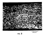
- the reasons for this state of affairs are not clearly established and, even by comparing the micrographic sections of the supports obtained from mat (FIG. 2) and from fabric (FIG. 3), these results cannot be anticipated.
- Figure 1 shows schematically in cross section the plates of a press (1), one stack of layers (4) of mat placed between two graphite spacers (2) provided with shims (3).
- Figure 2 is a micrograph (x 130) of the support obtained in Example 2, in cross section perpendicular to the support.
- Figure 3 is a micrograph (x 130) of the support obtained in Example 3, in cross section perpendicular to the support.
- FIG. 4a shows diagrammatically a support with a mat consisting of fiber segments substantially perpendicular to the axis Z having an external part c charged with fine powders (view in section along the axis Z perpendicular to the support).
- Figure 4b shows schematically a section of the support of Figure 4a along the axis AA ', perpendicular to the axis Z, and illustrates the random orientation of the carbon fiber segments.
- the substrate thus obtained is then carbonized by bringing the substrate as well as the two protective graphite spacers to 900 ° C., the rise in temperature being 12.5 ° C./h. Maintained 6 h level at 900 ° C. After cooling to room temperature, the substrate is separated from the graphite spacers. A manipulable, although fragile, substrate is obtained.
- the substrate is densified by impregnating with a phenolic resin which is crosslinked and carbonized in a known manner. After crosslinking the resin at 200 ° C, the apparent density of the support thus obtained at this stage is 1.25 and its permeability is between 30 and 60 cm3 / cm2.s.bar.
- Example 2 is analogous to Example 1 except that, after 24 h treatment at 250 ° C. to freeze the structure of the substrate, the substrate is densified directly with a phenolic resin.
- a step of carbonization at 900 ° C. of the polyacrylonitrile fiber mat in the crosslinked state has therefore been omitted, this carbonization being carried out during the carbonization of the phenolic resin.
- the apparent density is 0.96 and the permeability is between 130 and 180 cm3 / cm2.s.bar.
- a control test was carried out according to the prior art described in FR 2 582 956, starting not from a mat, as in the invention, but from carbon fiber fabric.
- a support of density 1 is obtained and having a permeability of 10 cm3 / cm2.s.bar and a porous diameter (1st pore diameter) of between 12 and 26 ⁇ m.
- Figure 3 is a photomicrograph of a section, perpendicular to the support obtained according to this example.
Landscapes
- Chemical & Material Sciences (AREA)
- Engineering & Computer Science (AREA)
- Ceramic Engineering (AREA)
- Chemical Kinetics & Catalysis (AREA)
- Structural Engineering (AREA)
- Organic Chemistry (AREA)
- Materials Engineering (AREA)
- Inorganic Chemistry (AREA)
- Separation Using Semi-Permeable Membranes (AREA)
- Ceramic Products (AREA)
- Filtering Materials (AREA)
- Carbon And Carbon Compounds (AREA)
- Laminated Bodies (AREA)
- Porous Artificial Stone Or Porous Ceramic Products (AREA)
Abstract
Description
L'invention concerne le domaine des éléments de filtration et est relatif, plus particulièrement, à un support destiné à recevoir une membrane pour techniques séparatives.The invention relates to the field of filtration elements and relates, more particularly, to a support intended to receive a membrane for separation techniques.
Dans les techniques séparatives, les procédés comme l'osmose inverse, l'ultrafiltration et la microfiltration ont recours, soit à des membranes organiques, soit depuis quelques années à des membranes minérales. Suivant le type d'utilisation, ces membranes doivent posséder des dimensions de pores faibles et appropriés à l'utilisation envisagée, une épaisseur minimale pour permettre une faible perte de charge à la filtration (perméabilité élevée). Enfin, dans le cas de membranes minérales, le support doit avoir des- caractéristiques mécaniques élevées.In separation techniques, processes such as reverse osmosis, ultrafiltration and microfiltration have used either organic membranes or, in recent years, mineral membranes. Depending on the type of use, these membranes must have small pore dimensions suitable for the intended use, a minimum thickness to allow a low pressure drop on filtration (high permeability). Finally, in the case of mineral membranes, the support must have high mechanical characteristics.
On connaît déjà l'intérêt des matériaux composite carbonecarbone (C-C en abrégé) pour réaliser des supports de membrane de filtration permettant de satisfaire les exigences déjà mentionnées. En outre, ces supports en composite C-C présentent une grande inertie chimique qui se traduit par une absence de contamination du filtrat, et par une absence de corrosion du support, du moins dans les conditions usuelles d'utilisation.The advantage of carbonecarbon composite materials (CC for short) is already known for producing filtration membrane supports making it possible to meet the requirements already mentioned. In addition, these CC composite supports have a high chemical inertness which results in an absence of contamination of the filtrate, and in an absence of corrosion of the support, at least under the usual conditions of use.
Ainsi, le brevet français No 2 582 956, au nom de la demanderesse, décrit un support de membrane minérale, constitué d'un matériau composite C-C de faible épaisseur dans lequel le substrat fibreux est constitué de textile en carbone (fibres et/ou tissu et/ou feutre), éventuellement associé à un mat de fibres disposées aléatoirement. Un tel support en matériau composite présente, bien que de faible épaisseur, des caractéristiques mécaniques suffisantes, en particulier une résistance à l'éclatement, à l'écrasement et à la flexion dans le cas de tubes.Thus, French patent No 2,582,956, in the name of the applicant, describes a mineral membrane support, made of a thin CC composite material in which the fibrous substrate consists of carbon textile (fibers and / or fabric and / or felt), possibly associated with a mat of fibers arranged randomly. Such a support made of composite material has, although thin, sufficient mechanical characteristics, in particular a resistance to bursting, crushing and bending in the case of tubes.
Les supports de membrane décrits dans le FR 2 582 956 présentent déjà des performances élevées, mais la demanderesse a observé qu'ils n'étaient pas adaptés comme supports de membranes minces à cause de l'irrégularité de leur surface : en effet, plus la membrane est mince, plus la surface du support en contact avec la membrane doit être régulière, sans rugosité et surtout sans gros défaut de surface, sinon il est difficile, voire impossible de déposer une membrane d'épaisseur régulière. En outre, les irrégularités de surface du support peuvent se transmettre, du moins en partie, à la surface de la membrane elle-même. De plus, si la surface de la membrane présente le moins d'aspérités possible et est la moins rugueuse possible, elle peut être nettoyée et décolmatée plus facilement.
La demanderesse a donc poursuivi ses recherches pour résoudre ce problème et plus généralement pour mettre au point des supports de membrane permettant d'obtenir la perméabilité la plus élevée possible, et donc la vitesse de filtration la plus grande possible.The membrane supports described in FR 2 582 956 already exhibit high performance, but the Applicant has observed that they were not suitable as supports for thin membranes because of the irregularity of their surface: in fact, the more membrane is thin, the more the surface of the support in contact with the membrane must be regular, without roughness and especially without large surface defect, otherwise it is difficult, even impossible to deposit a membrane of regular thickness. In addition, the surface irregularities of the support can be transmitted, at least in part, to the surface of the membrane itself. In addition, if the surface of the membrane has the least roughness possible and is the least rough possible, it can be cleaned and unclogged more easily.
The Applicant has therefore continued its research to solve this problem and more generally to develop membrane supports making it possible to obtain the highest possible permeability, and therefore the highest possible filtration speed.
Selon l'invention, le support destiné à recevoir une membrane utilisable pour les techniques séparatives est constitué d'un matériau composite carbone-carbone, de faible épaisseur selon la direction Z de passage du flux à traiter, solide mécaniquement, d'une texture poreuse appropriée à la membrane, comprenant un substrat fibreux et une matrice carbonée poreuse, et caractérisé en ce que, de manière à augmenter la perméabilité et à réduire la rugosité de la face externe du support destinée à être en contact avec ladite membrane, le substrat fibreux est un mat de fibres de carbone, constitué de segments de fibres contenus dans un plan perpendiculaire à l'axe Z et orientés aléatoirement dans ce plan et en ce qu'éventuellement, une fraction du support destinée à être en contact avec ladite membrane contienne une dispersion de fine poudre inerte permettant d'ajuster le diamètre des pores de la face externe du support.According to the invention, the support intended to receive a membrane usable for separation techniques consists of a carbon-carbon composite material, of small thickness in the direction Z of passage of the flux to be treated, mechanically solid, of a porous texture suitable for the membrane, comprising a fibrous substrate and a porous carbon matrix, and characterized in that, so as to increase the permeability and reduce the roughness of the external face of the support intended to be in contact with said membrane, the fibrous substrate is a mat of carbon fibers, consisting of segments of fibers contained in a plane perpendicular to the axis Z and randomly oriented in this plane and in that possibly, a fraction of the support intended to be in contact with said membrane contains a dispersion of fine inert powder to adjust the pore diameter of the external face of the support.
Un mat est une nappe non-tissée constituée d'une dispersion aléatoire de fibres de relativement faible longueur dans le plan. Il s'agit d'une orientation aléatoire bidimensionnelle de segments de fibres qui constitue un enchevêtrement liant les segments entre eux et permettant la manipulation de la nappe ainsi constituée. La figure 4b est une représentation schématique de cette orientation aléatoire dans un plan perpendiculaire à l'axe Z.A mat is a nonwoven web made up of a random dispersion of fibers of relatively short length in the plane. It is a two-dimensional random orientation of fiber segments which constitutes an entanglement binding the segments together and allowing the manipulation of the sheet thus formed. FIG. 4b is a schematic representation of this random orientation in a plane perpendicular to the Z axis.
A la suite de ses recherches, la demanderesse a observé qu'il était particulièrement avantageux d'utiliser comme substrat un renfort fibreux constitué seulement d'un mat de fibres de carbone ou d'un empilement de mats. En effet, un substrat seulement constitué de mat de fibres de carbone (fraction volumique comprise entre 15 et 55% et de préférence entre 25 et 45% du volume total) permet :
- d'une part, d'obtenir un support de caractéristiques mécaniques sensiblement comparables à celles obtenues avec un substrat comportant un tissu ou un feutre de fibres de carbone.
- d'autre part, d'améliorer la régularité de la surface du support, comparativement à un support dont le substrat de "surface" est un tissu ou un feutre.
- enfin et surtout, d'accroître dans de grandes proportions la perméabilité du support. On atteint jusqu'à 25 fois la perméabilité obtenue selon l'art antérieur, ce qui est considérable et du plus grand intérêt d'un point de vue pratique.
- on the one hand, to obtain a support of characteristics mechanical substantially comparable to those obtained with a substrate comprising a fabric or a felt of carbon fibers.
- on the other hand, to improve the regularity of the surface of the support, compared to a support whose "surface" substrate is a fabric or a felt.
- last but not least, to increase the permeability of the support in large proportions. The permeability obtained according to the prior art is reached up to 25 times, which is considerable and of great interest from a practical point of view.
Selon l'invention, le substrat constitué de mat qui permet d'atteindre ces performances est obtenu de la manière suivante :
On part de mats en fibres de carbone ou, préférentiellement, de précurseur de carbone éventuellement à l'état réticulé. Ces mats de départ sont constitués d'enchevêtrements bidimensionnels de segments de fibres en carbone ou en précurseurs de carbone de longueur moyenne comprise entre 1 et 100 mm et de préférence comprise entre 20 et 80 mm. Leur masse surfacique est généralement comprise entre 50 et 300 g/m². Le mat peut être éventuellement aiguilleté.
On positionne le mat sur un support ayant la forme requise, rigide de préférence, et n'adhérant pas au mat et on empile eventuellement plusieurs couches de mat, le nombre de couches nécessaires en fonction notamment de l'épaisseur du support final. L'empilement des couches de mat est ensuite comprimé à froid sous une pression comprise entre 5 et 10 MPa, et porté à une température comprise entre 100 - 300°C pendant une durée comprise entre 1 et 50 heures pour figer la structure fibreuse. La densité apparente du substrat fibreux comprimé ainsi obtenu est comprise entre 0,2 et 0,6 et, de préférence voisine de 0,5.According to the invention, the substrate made of mat which enables these performances to be achieved is obtained in the following manner:
We start from carbon fiber mats or, preferably, carbon precursor optionally in the crosslinked state. These starting mats consist of two-dimensional tangles of segments of carbon fibers or carbon precursors of average length between 1 and 100 mm and preferably between 20 and 80 mm. Their surface mass is generally between 50 and 300 g / m². The mat can possibly be needled.
The mat is positioned on a support having the required shape, preferably rigid, and not adhering to the mat and possibly stacking several layers of mat, the number of layers required depending in particular on the thickness of the final support. The stack of mat layers is then cold pressed at a pressure between 5 and 10 MPa, and brought to a temperature between 100 - 300 ° C for a period between 1 and 50 hours to freeze the fibrous structure. The apparent density of the compressed fibrous substrate thus obtained is between 0.2 and 0.6 and preferably around 0.5.
Lorsqu'on part de mat de fibres en précurseur de carbone, on peut ensuite éventuellement réaliser une carbonisation entre 800 et 1200°C qui transformera le précurseur en fibre de carbone.
On densifie ensuite de manière connue le substrat fibreux obtenu précédemment et éventuellement carbonisé, soit par imprégnation et carbonisation d'une résine de préférence choisie pour laisser un taux de coke élevé par carbonisation, soit par dépôt chimique de carbone en phase vapeur, soit enfin par une combinaison de ces deux moyens. La densité finale du support poreux est comprise entre 0,7 et 1,2 et préférentiellement entre 0,8 et 1 de manière à avoir simultanémént des caractéristique mécaniques et une perméabilité suffisantes.When one starts from a mat of fibers as a carbon precursor, one can then optionally carry out carbonization between 800 and 1200 ° C. which will transform the precursor into carbon fiber.
The fibrous substrate obtained previously and optionally carbonized is then densified in known manner, either by impregnation and carbonization of a resin preferably chosen to leave a high coke content by carbonization, or by chemical vapor deposition of carbon, or finally by a combination of these two means. The final density of the porous support is between 0.7 and 1.2 and preferably between 0.8 and 1 so as to simultaneously have sufficient mechanical characteristics and permeability.
Selon l'invention, on peut incorporer des poudres fines aux mats lors de leur empilement. Ces poudres peuvent être constituées de fibres broyées en matériau inerte, notamment vis à vis du carbone (poudres de fibre de carbone, fibre de verre, carbure de silicium etc...), capables de modifier le diamètre des pores. En particulier, il est avantageux de modifier ainsi la couche externe de mat destinée à être en contact avec la membrane de manière à avoir, surtout dans le cas d'une membrane très mince, un support à surface très régulière et à porosité adaptée, et ceci sans réduire significativement la perméabilité du support puisque seule une faible épaisseur du support a été modifié. Par ailleurs, un support dont une face externe a été ainsi modifiée peut éventuellement être utilisé tel quel comme élément filtrant sans adjonction de membrane.
Ces poudres ont une taille particulaire moyenne comprise entre 0,1 et 10 µm et, dans la partie externe du support où elles sont présentes, elles occupent une fraction volumique comprise entre 1 et 20% du volume total et de préférence environ 5 % du volume total.According to the invention, fine powders can be incorporated into the mats when they are stacked. These powders can be made up of ground fibers of inert material, in particular with respect to carbon (carbon fiber powders, glass fiber, silicon carbide, etc.), capable of modifying the diameter of the pores. In particular, it is advantageous to thus modify the external mat layer intended to be in contact with the membrane so as to have, especially in the case of a very thin membrane, a support with a very regular surface and with suitable porosity, and this without significantly reducing the permeability of the support since only a small thickness of the support has been modified. Furthermore, a support whose external face has thus been modified can optionally be used as such as a filter element without the addition of a membrane.
These powders have an average particle size of between 0.1 and 10 μm and, in the external part of the support where they are present, they occupy a volume fraction of between 1 and 20% of the total volume and preferably about 5% of the volume. total.
Bien que l'invention se prête particulièrement bien à la fabrication de support poreux de membrane filtrante sous forme de plaques planes, par compression à la presse à plateaux chauffés, il est possible selon l'invention d'obtenir un support de n'importe quelle forme, un tube par exemple, par compression isostatique sur un support de "forme" ayant la forme recherchée, le support de "forme" et sa couche de mat étant placés dans une enceinte souple et étanche, par exemple un sac plastique de préférence thermorétractable, stable thermiquement, la compression étant suivie d'un traitement thermique à 100-300°C puis du retrait de l'enceinte souple et éventuellement du support de "forme" avant densification selon les moyens déjà mentionnés.Although the invention lends itself particularly well to the production of a porous support for a filter membrane in the form of flat plates, by compression with a press with heated plates, it is possible according to the invention to obtain a support of any form, a tube for example, by isostatic compression on a support of "shape" having the desired shape, the support of "shape" and its mat layer being placed in a flexible and waterproof enclosure, for example a plastic bag preferably heat-shrinkable , thermally stable, the compression being followed by a heat treatment at 100-300 ° C. then by the withdrawal of the flexible enclosure and possibly of the "shape" support before densification according to the means already mentioned.
Les résultats obtenus selon l'invention sont particulièrement surprenants en ce qui concerne surtout la perméabilité, qui est 25 fois plus grande pour le support obtenu selon l'exemple 2 de l'invention que pour le support de l'exemple 3 obtenu selon l'art antérieur. Les raisons de cet état de fait ne sont pas clairement établies et, même en comparant les coupes micrographiques des supports obtenus à partir de mat (figure 2) et à partir de tissu (figure 3), on ne peut anticiper ces résultats.The results obtained according to the invention are particularly surprising as regards above all the permeability, which is 25 times greater for the support obtained according to example 2 of the invention than for the support of example 3 obtained according to prior art. The reasons for this state of affairs are not clearly established and, even by comparing the micrographic sections of the supports obtained from mat (FIG. 2) and from fabric (FIG. 3), these results cannot be anticipated.
La figure 1 schématise en coupe transversale les plateaux d'une presse (1), l'un empilement de couches (4) de mat placé entre deux intercalaires en graphite (2) munis de cales d'épaisseur (3).Figure 1 shows schematically in cross section the plates of a press (1), one stack of layers (4) of mat placed between two graphite spacers (2) provided with shims (3).
La figure 2 est une micrographie ( x 130 ) du support obtenu à l'exemple 2, en coupe transversale perpendiculairement au support.Figure 2 is a micrograph (x 130) of the support obtained in Example 2, in cross section perpendicular to the support.
La figure 3 est une micrographie ( x 130 ) du support obtenu à l'exemple 3, en coupe transversale perpendiculairement au support.Figure 3 is a micrograph (x 130) of the support obtained in Example 3, in cross section perpendicular to the support.
La figure 4a schématise un support avec comme substrat un mat constitué de segments de fibres sensiblement perpendiculaires à l'axe Z présentant une partie externe c chargée de fines poudres (vue en coupe selon l'axe Z perpendiculaire au support).
La figure 4b schématise une coupe du support de la figure 4a selon l'axe AA′, perpendiculairement à l'axe Z, et illustre l'orientation aléatoire des segments de fibres de carbone.FIG. 4a shows diagrammatically a support with a mat consisting of fiber segments substantially perpendicular to the axis Z having an external part c charged with fine powders (view in section along the axis Z perpendicular to the support).
Figure 4b shows schematically a section of the support of Figure 4a along the axis AA ', perpendicular to the axis Z, and illustrates the random orientation of the carbon fiber segments.
Les exemples qui suivent illustrent l'invention :
- Les exemples 1 et 2 correspondent à l'invention.
- L'exemple 3 est un essai comparatif selon l'art antérieur.
- Examples 1 and 2 correspond to the invention.
- Example 3 is a comparative test according to the prior art.
On part de mat de fibre en précurseur de carbone ( fibre polyacrylonitrile à l'état réticulé ) dont la masse surfacique est de 130 g/m². La longueur moyenne des fibres est de 63 mm.
La densité apparente est de 0,01.
On empile 10 couches de mat, soit une épaisseur de 13 mm et on comprime l'ensemble entre les deux plateaux métalliques (1) d'une presse munie d'intercalaires en graphite (2) jusqu'à une épaisseur de 1,5 mm (l'épaisseur est déterminée par les cales (3)).La densité apparente est alors de 0,5.
On porte l'empilement de mat comprimé à 250°C et on le maintient à cette température pendant 24 h pour figer la structure.
On carbonise ensuite le substrat ainsi obtenu en portant à 900°C le substrat ainsi que les deux intercalaires graphite de protection, la montée en température étant de 12,5°C/h. On maintient 6 h en palier à 900°C.
Après refroidissement à la température ambiante, on sépare le substrat des intercalaires graphite. On obtient un substrat manipulable, quoique fragile.
On densifie le substrat par imprégnation d'une résine phénolique que l'on réticule et carbonise de manière connue. Après réticulation de la résine à 200°C, la densité apparente du support ainsi obtenu à ce stade est de 1,25 et sa perméabilité est comprise entre 30 et 60 cm³/cm².s.bar. Après carbonisation à 900 °C, on obtient un support de densité apparente de 0,86 et de perméabilité de 165 cm³/cm².s.bar et de diamètre poreux (diamètre de 1er pore) compris entre 32 et 34 µm.L'état de la surface a été caractérisé par sa rugosité :
RT = 30 - 40 µm et RA = 4 - 5 µmWe start from a fiber mat made of carbon precursor (polyacrylonitrile fiber in the crosslinked state) whose surface mass is 130 g / m². The average length of the fibers is 63 mm.
The bulk density is 0.01.
We stack 10 layers of mat, a thickness of 13 mm and we compress the assembly between the two metal plates (1) of a press fitted with graphite spacers (2) to a thickness of 1.5 mm (the thickness is determined by the shims (3). The apparent density is then 0.5.
The stack of compressed mat is brought to 250 ° C. and kept at this temperature for 24 h to freeze the structure.
The substrate thus obtained is then carbonized by bringing the substrate as well as the two protective graphite spacers to 900 ° C., the rise in temperature being 12.5 ° C./h. Maintained 6 h level at 900 ° C.
After cooling to room temperature, the substrate is separated from the graphite spacers. A manipulable, although fragile, substrate is obtained.
The substrate is densified by impregnating with a phenolic resin which is crosslinked and carbonized in a known manner. After crosslinking the resin at 200 ° C, the apparent density of the support thus obtained at this stage is 1.25 and its permeability is between 30 and 60 cm³ / cm².s.bar. After carbonization at 900 ° C, a support with an apparent density of 0.86 and a permeability of 165 cm³ / cm².s.bar and a porous diameter (diameter of the 1st pore) of between 32 and 34 μm is obtained. of the surface was characterized by its roughness:
R T = 30 - 40 µm and R A = 4 - 5 µm
L'exemple 2 est analogue à l'exemple 1 sauf que, après le traitement de 24 h à 250°C pour figer la structure du substrat, on densifie directement le substrat avec une résine phénolique.
Dans cet exemple, on a donc supprimé une étape de carbonisation à 900°C du mat en fibre polyacrylonitrile à l'état réticulé, cette carbonisation étant réalisée durant la carbonisation de la résine phénolique.
Après imprégnation avec la résine pénolique et réticulation, la densité apparente est de 0,96 et la perméabilité est comprise entre 130 et 180 cm³/cm².s.bar. Après carbonisation à 900°C, on obtient un support de 0,90 de densité apparente et de 250 cm³/cm².s.bar de perméabilité et de diamètre poreux (diamètre 1er pore) compris entre 34 et 43 µm.
L'état de la surface a été caractérisé par sa rugosité :
RT = 30 - 40 µm et RA = 4 - 5 µm
La figure 2 est une microphotographie d'une coupe perpendiculairement au support obtenu selon cet exempleExample 2 is analogous to Example 1 except that, after 24 h treatment at 250 ° C. to freeze the structure of the substrate, the substrate is densified directly with a phenolic resin.
In this example, a step of carbonization at 900 ° C. of the polyacrylonitrile fiber mat in the crosslinked state has therefore been omitted, this carbonization being carried out during the carbonization of the phenolic resin.
After impregnation with the penolic resin and crosslinking, the apparent density is 0.96 and the permeability is between 130 and 180 cm³ / cm².s.bar. After carbonization at 900 ° C, a support of 0.90 apparent density and 250 cm³ / cm².s.bar of permeability and porous diameter (1st pore diameter) of between 34 and 43 μm is obtained.
The condition of the surface was characterized by its roughness:
R T = 30 - 40 µm and R A = 4 - 5 µm
Figure 2 is a photomicrograph of a section perpendicular to the support obtained according to this example
On a réalisé un essai témoin selon l'art antérieur décrit dans le FR 2 582 956, en partant non pas de mat, comme dans l'invention, mais de tissu en fibre de carbone.
On a imprégné, avec la résine phénolique utilisée dans les deux exemples précédents, un tissu à 300 g/m² en fibres de carbone. Après carbonisation à 900°C, on obtient un support de densité 1 et ayant une perméabilité de 10 cm³/cm².s.bar et un diamètre poreux (diamètre 1er pore) compris entre 12 et 26 µm.
L'état de la surface a été caractérisé par sa rugosité :
RT = 50 - 60 µm et RA = 6 - 8 µm
La figure 3 est une microphotographie d'une coupe, perpendiculairement au support obtenu selon cet exemple.A control test was carried out according to the prior art described in FR 2 582 956, starting not from a mat, as in the invention, but from carbon fiber fabric.
Was impregnated with the phenolic resin used in the two previous examples, a fabric at 300 g / m² of carbon fibers. After carbonization at 900 ° C, a support of density 1 is obtained and having a permeability of 10 cm³ / cm².s.bar and a porous diameter (1st pore diameter) of between 12 and 26 μm.
The condition of the surface was characterized by its roughness:
R T = 50 - 60 µm and R A = 6 - 8 µm
Figure 3 is a photomicrograph of a section, perpendicular to the support obtained according to this example.
Claims (11)
Applications Claiming Priority (2)
| Application Number | Priority Date | Filing Date | Title |
|---|---|---|---|
| FR9009352 | 1990-07-17 | ||
| FR9009352A FR2664889B1 (en) | 1990-07-17 | 1990-07-17 | POROUS CARBON-CARBON COMPOSITE FILTERING MEMBRANE SUPPORT WITH CARBON FIBER SUBSTRATE AND MANUFACTURING METHOD THEREOF. |
Publications (2)
| Publication Number | Publication Date |
|---|---|
| EP0467806A1 true EP0467806A1 (en) | 1992-01-22 |
| EP0467806B1 EP0467806B1 (en) | 1995-08-23 |
Family
ID=9398976
Family Applications (1)
| Application Number | Title | Priority Date | Filing Date |
|---|---|---|---|
| EP91420252A Expired - Lifetime EP0467806B1 (en) | 1990-07-17 | 1991-07-15 | Porous carbon/carbon composite filter membrane support with a carbon fiber mat substrate and process of manufacturing the same |
Country Status (8)
| Country | Link |
|---|---|
| US (1) | US5238568A (en) |
| EP (1) | EP0467806B1 (en) |
| JP (1) | JPH05131121A (en) |
| AT (1) | ATE126721T1 (en) |
| DE (1) | DE69112313T2 (en) |
| DK (1) | DK0467806T3 (en) |
| ES (1) | ES2076496T3 (en) |
| FR (1) | FR2664889B1 (en) |
Cited By (1)
| Publication number | Priority date | Publication date | Assignee | Title |
|---|---|---|---|---|
| EP0495735A1 (en) * | 1991-01-18 | 1992-07-22 | Le Carbone Lorraine | Process for manufacturing highly permeable porous tubes from carbon-carbon composite material and their uses |
Families Citing this family (11)
| Publication number | Priority date | Publication date | Assignee | Title |
|---|---|---|---|---|
| IL109497A (en) * | 1993-05-05 | 1998-02-22 | Hyperion Catalysis Int | Three-dimensional macroscopic assemblages of randomly oriented carbon fibrils and composites containing same |
| CN1211199C (en) * | 1996-05-15 | 2005-07-20 | 海珀里昂催化国际有限公司 | Rigid porous carbon structure, method of making, method of using and products contg. same |
| US5703359A (en) * | 1996-07-29 | 1997-12-30 | Leybold Inficon, Inc. | Composite membrane and support assembly |
| US5904854A (en) * | 1997-01-31 | 1999-05-18 | Electrophor, Inc. | Method for purifying water |
| MXPA02000576A (en) * | 1999-07-21 | 2002-08-30 | Hyperion Catalysis Int | Methods of oxidizing multiwalled carbon nanotubes. |
| DE10003176C2 (en) * | 2000-01-25 | 2001-11-22 | Deutsch Zentr Luft & Raumfahrt | Calibration body and use of the same |
| FR2927635B1 (en) * | 2008-02-14 | 2010-06-25 | Snecma Propulsion Solide | SEPARATION MEMBRANE FOR ELECTROLYSIS INSTALLATION |
| CN102405061B (en) | 2009-03-19 | 2015-12-09 | Emd密理博公司 | Nanofiber filter media is used to remove microorganism from fluid sample |
| EP2694196B1 (en) | 2011-04-01 | 2021-07-21 | EMD Millipore Corporation | Nanofiber containing composite structures |
| KR102206959B1 (en) | 2015-04-17 | 2021-01-25 | 이엠디 밀리포어 코포레이션 | Method of purifying a biological material of interest in a sample using nanofiber ultrafiltration membranes operated in tangential flow filtration mode |
| JP7296759B2 (en) * | 2019-03-29 | 2023-06-23 | 三菱製紙株式会社 | Semipermeable membrane support and filtration membrane for membrane separation activated sludge treatment |
Citations (5)
| Publication number | Priority date | Publication date | Assignee | Title |
|---|---|---|---|---|
| US4039341A (en) * | 1970-02-23 | 1977-08-02 | National Research Development Corporation | Production of carbon articles |
| DE2722575A1 (en) * | 1976-05-18 | 1977-12-22 | Morganite Modmor Ltd | COAL-CHARCOAL COMPOSITE |
| GB2003845A (en) * | 1977-09-09 | 1979-03-21 | Kanebo Ltd | Carbon-carbon composite material and method for its production |
| EP0208629A1 (en) * | 1985-06-10 | 1987-01-14 | Le Carbone Lorraine | Process for manufacturing an inorganic membrane support for separation techniques |
| EP0252339A1 (en) * | 1986-06-25 | 1988-01-13 | Akzo N.V. | Process for the preparation of porous carbon membranes |
Family Cites Families (5)
| Publication number | Priority date | Publication date | Assignee | Title |
|---|---|---|---|---|
| JPS57166354A (en) * | 1981-04-01 | 1982-10-13 | Kureha Chemical Ind Co Ltd | Porous carbon formed body and manufacture |
| EP0160916B1 (en) * | 1984-04-27 | 1991-07-10 | Fuji Photo Film Co., Ltd. | Part of an analytical element for the analysis of a solid in a liquid sample |
| US4582750A (en) * | 1985-04-16 | 1986-04-15 | E. I. Du Pont De Nemours And Company | Process for making a nonwoven fabric of needling, heating, burnishing and cooling |
| US4687697A (en) * | 1985-09-11 | 1987-08-18 | Lydall, Inc. | Composite having improved transverse structural integrity and flexibility for use in high temperature environments |
| DE3533924A1 (en) * | 1985-09-24 | 1987-06-19 | Schumacher Sche Fab Verwalt | FILTER BODY AND METHOD FOR THE PRODUCTION THEREOF |
-
1990
- 1990-07-17 FR FR9009352A patent/FR2664889B1/en not_active Expired - Fee Related
-
1991
- 1991-07-15 DE DE69112313T patent/DE69112313T2/en not_active Expired - Fee Related
- 1991-07-15 ES ES91420252T patent/ES2076496T3/en not_active Expired - Lifetime
- 1991-07-15 DK DK91420252.8T patent/DK0467806T3/en active
- 1991-07-15 AT AT91420252T patent/ATE126721T1/en not_active IP Right Cessation
- 1991-07-15 EP EP91420252A patent/EP0467806B1/en not_active Expired - Lifetime
- 1991-07-16 US US07/730,646 patent/US5238568A/en not_active Expired - Lifetime
- 1991-07-17 JP JP3176913A patent/JPH05131121A/en active Pending
Patent Citations (5)
| Publication number | Priority date | Publication date | Assignee | Title |
|---|---|---|---|---|
| US4039341A (en) * | 1970-02-23 | 1977-08-02 | National Research Development Corporation | Production of carbon articles |
| DE2722575A1 (en) * | 1976-05-18 | 1977-12-22 | Morganite Modmor Ltd | COAL-CHARCOAL COMPOSITE |
| GB2003845A (en) * | 1977-09-09 | 1979-03-21 | Kanebo Ltd | Carbon-carbon composite material and method for its production |
| EP0208629A1 (en) * | 1985-06-10 | 1987-01-14 | Le Carbone Lorraine | Process for manufacturing an inorganic membrane support for separation techniques |
| EP0252339A1 (en) * | 1986-06-25 | 1988-01-13 | Akzo N.V. | Process for the preparation of porous carbon membranes |
Cited By (1)
| Publication number | Priority date | Publication date | Assignee | Title |
|---|---|---|---|---|
| EP0495735A1 (en) * | 1991-01-18 | 1992-07-22 | Le Carbone Lorraine | Process for manufacturing highly permeable porous tubes from carbon-carbon composite material and their uses |
Also Published As
| Publication number | Publication date |
|---|---|
| FR2664889A1 (en) | 1992-01-24 |
| DE69112313D1 (en) | 1995-09-28 |
| EP0467806B1 (en) | 1995-08-23 |
| DE69112313T2 (en) | 1996-01-25 |
| US5238568A (en) | 1993-08-24 |
| DK0467806T3 (en) | 1995-12-27 |
| JPH05131121A (en) | 1993-05-28 |
| ATE126721T1 (en) | 1995-09-15 |
| FR2664889B1 (en) | 1992-09-25 |
| ES2076496T3 (en) | 1995-11-01 |
Similar Documents
| Publication | Publication Date | Title |
|---|---|---|
| EP0467806B1 (en) | Porous carbon/carbon composite filter membrane support with a carbon fiber mat substrate and process of manufacturing the same | |
| EP2785665B1 (en) | Cmc material part manufacture method | |
| EP2146110A1 (en) | Method for producing a friction part from a carbon/carbon composite material | |
| EP1886046B1 (en) | Method and substrate for making composite material parts by chemical vapour infiltration densification and resulting parts | |
| EP2253604B1 (en) | Part made from a C/C composite material and method for manufacturing same | |
| EP0581696B1 (en) | Carbon/carbon composite friction material with divided porosity | |
| EP0819105B1 (en) | Chemical vapour infiltration method with variable infiltration parameters | |
| EP0472476A2 (en) | Process for the production of a asymmetric ultrathin mineral membrane | |
| EP0208629B1 (en) | Process for manufacturing an inorganic membrane support for separation techniques | |
| EP0886627A1 (en) | Method for making parts, in particular brake disks, in composite carbon-carbon material | |
| FR2849651A1 (en) | INSULATING STRUCTURES COMPRISING LAYERS OF EXPANDED GRAPHITE PARTICLES COMPRESSED AT DIFFERENT DENSITIES, THERMAL INSULATING ELEMENTS MADE FROM THESE STRUCTURES | |
| EP0495735A1 (en) | Process for manufacturing highly permeable porous tubes from carbon-carbon composite material and their uses | |
| FR2754031A1 (en) | DEVELOPMENT OF FIBROUS PREFORMS FOR THE MANUFACTURE OF COMPOSITE MATERIAL BRAKE DISCS | |
| EP0223642B1 (en) | Carbon-carbon composite material for friction members and its use in brakes | |
| CA3014449A1 (en) | Method for manufacturing a part made of a ceramic matrix composite material | |
| EP0555130B1 (en) | Method of making composite material parts having a ceramic matrix | |
| EP0250346B1 (en) | Process for the production of a porous mineral membrane on an inorganic support | |
| EP0735387A1 (en) | Method for manufacturing a lightweight SiC structure of the sandwich type with a honeycomb core and the structure so obtained | |
| EP1054091A1 (en) | Unidirectional web of carbon fibers | |
| EP0598631A1 (en) | Oxidation-resistant carbon-carbon composite material with SiC-doped matrix and method of producing said material | |
| EP0558417A1 (en) | Method of making carbon/carbon-composite articles from mesophase powder | |
| US10323339B2 (en) | Aircraft brake disc materials and methods | |
| EP0555134A1 (en) | Process for manufacturing of shaped fibrous structure for fabricating a composite material and products obtained thereby | |
| EP0482968B1 (en) | Silicon carbide matrix composite useable as flame protection layer | |
| EP0236396A1 (en) | Mandrel for the fabrication of hollow parts having an armature. |
Legal Events
| Date | Code | Title | Description |
|---|---|---|---|
| PUAI | Public reference made under article 153(3) epc to a published international application that has entered the european phase |
Free format text: ORIGINAL CODE: 0009012 |
|
| AK | Designated contracting states |
Kind code of ref document: A1 Designated state(s): AT BE CH DE DK ES GB IT LI LU NL SE |
|
| 17P | Request for examination filed |
Effective date: 19920207 |
|
| 17Q | First examination report despatched |
Effective date: 19930811 |
|
| GRAA | (expected) grant |
Free format text: ORIGINAL CODE: 0009210 |
|
| AK | Designated contracting states |
Kind code of ref document: B1 Designated state(s): AT BE CH DE DK ES GB IT LI LU NL SE |
|
| REF | Corresponds to: |
Ref document number: 126721 Country of ref document: AT Date of ref document: 19950915 Kind code of ref document: T |
|
| ITF | It: translation for a ep patent filed |
Owner name: ING. A. GIAMBROCONO & C. S.R.L. |
|
| GBT | Gb: translation of ep patent filed (gb section 77(6)(a)/1977) |
Effective date: 19950821 |
|
| REF | Corresponds to: |
Ref document number: 69112313 Country of ref document: DE Date of ref document: 19950928 |
|
| REG | Reference to a national code |
Ref country code: ES Ref legal event code: FG2A Ref document number: 2076496 Country of ref document: ES Kind code of ref document: T3 |
|
| REG | Reference to a national code |
Ref country code: DK Ref legal event code: T3 |
|
| PLBE | No opposition filed within time limit |
Free format text: ORIGINAL CODE: 0009261 |
|
| STAA | Information on the status of an ep patent application or granted ep patent |
Free format text: STATUS: NO OPPOSITION FILED WITHIN TIME LIMIT |
|
| 26N | No opposition filed | ||
| PGFP | Annual fee paid to national office [announced via postgrant information from national office to epo] |
Ref country code: GB Payment date: 20010618 Year of fee payment: 11 |
|
| PGFP | Annual fee paid to national office [announced via postgrant information from national office to epo] |
Ref country code: AT Payment date: 20010622 Year of fee payment: 11 |
|
| PGFP | Annual fee paid to national office [announced via postgrant information from national office to epo] |
Ref country code: DE Payment date: 20010625 Year of fee payment: 11 |
|
| PGFP | Annual fee paid to national office [announced via postgrant information from national office to epo] |
Ref country code: DK Payment date: 20010626 Year of fee payment: 11 |
|
| PGFP | Annual fee paid to national office [announced via postgrant information from national office to epo] |
Ref country code: SE Payment date: 20010627 Year of fee payment: 11 Ref country code: CH Payment date: 20010627 Year of fee payment: 11 |
|
| PGFP | Annual fee paid to national office [announced via postgrant information from national office to epo] |
Ref country code: LU Payment date: 20010710 Year of fee payment: 11 |
|
| PGFP | Annual fee paid to national office [announced via postgrant information from national office to epo] |
Ref country code: ES Payment date: 20010713 Year of fee payment: 11 |
|
| PGFP | Annual fee paid to national office [announced via postgrant information from national office to epo] |
Ref country code: NL Payment date: 20010731 Year of fee payment: 11 |
|
| PGFP | Annual fee paid to national office [announced via postgrant information from national office to epo] |
Ref country code: BE Payment date: 20010904 Year of fee payment: 11 |
|
| REG | Reference to a national code |
Ref country code: GB Ref legal event code: IF02 |
|
| PG25 | Lapsed in a contracting state [announced via postgrant information from national office to epo] |
Ref country code: LU Free format text: LAPSE BECAUSE OF NON-PAYMENT OF DUE FEES Effective date: 20020715 Ref country code: GB Free format text: LAPSE BECAUSE OF NON-PAYMENT OF DUE FEES Effective date: 20020715 Ref country code: AT Free format text: LAPSE BECAUSE OF NON-PAYMENT OF DUE FEES Effective date: 20020715 |
|
| PG25 | Lapsed in a contracting state [announced via postgrant information from national office to epo] |
Ref country code: SE Free format text: LAPSE BECAUSE OF NON-PAYMENT OF DUE FEES Effective date: 20020716 Ref country code: ES Free format text: LAPSE BECAUSE OF NON-PAYMENT OF DUE FEES Effective date: 20020716 |
|
| PG25 | Lapsed in a contracting state [announced via postgrant information from national office to epo] |
Ref country code: LI Free format text: LAPSE BECAUSE OF NON-PAYMENT OF DUE FEES Effective date: 20020731 Ref country code: DK Free format text: LAPSE BECAUSE OF NON-PAYMENT OF DUE FEES Effective date: 20020731 Ref country code: CH Free format text: LAPSE BECAUSE OF NON-PAYMENT OF DUE FEES Effective date: 20020731 Ref country code: BE Free format text: LAPSE BECAUSE OF NON-PAYMENT OF DUE FEES Effective date: 20020731 |
|
| BERE | Be: lapsed |
Owner name: *LE CARBONE LORRAINE Effective date: 20020731 |
|
| PG25 | Lapsed in a contracting state [announced via postgrant information from national office to epo] |
Ref country code: NL Free format text: LAPSE BECAUSE OF NON-PAYMENT OF DUE FEES Effective date: 20030201 Ref country code: DE Free format text: LAPSE BECAUSE OF NON-PAYMENT OF DUE FEES Effective date: 20030201 |
|
| EUG | Se: european patent has lapsed | ||
| GBPC | Gb: european patent ceased through non-payment of renewal fee |
Effective date: 20020715 |
|
| REG | Reference to a national code |
Ref country code: DK Ref legal event code: EBP |
|
| REG | Reference to a national code |
Ref country code: CH Ref legal event code: PL |
|
| NLV4 | Nl: lapsed or anulled due to non-payment of the annual fee |
Effective date: 20030201 |
|
| REG | Reference to a national code |
Ref country code: ES Ref legal event code: FD2A Effective date: 20030811 |
|
| PG25 | Lapsed in a contracting state [announced via postgrant information from national office to epo] |
Ref country code: IT Free format text: LAPSE BECAUSE OF NON-PAYMENT OF DUE FEES;WARNING: LAPSES OF ITALIAN PATENTS WITH EFFECTIVE DATE BEFORE 2007 MAY HAVE OCCURRED AT ANY TIME BEFORE 2007. THE CORRECT EFFECTIVE DATE MAY BE DIFFERENT FROM THE ONE RECORDED. Effective date: 20050715 |