EP0417805B1 - Control method and device for AC motor - Google Patents
Control method and device for AC motor Download PDFInfo
- Publication number
- EP0417805B1 EP0417805B1 EP90117738A EP90117738A EP0417805B1 EP 0417805 B1 EP0417805 B1 EP 0417805B1 EP 90117738 A EP90117738 A EP 90117738A EP 90117738 A EP90117738 A EP 90117738A EP 0417805 B1 EP0417805 B1 EP 0417805B1
- Authority
- EP
- European Patent Office
- Prior art keywords
- inverter
- power
- converter
- producing
- command value
- Prior art date
- Legal status (The legal status is an assumption and is not a legal conclusion. Google has not performed a legal analysis and makes no representation as to the accuracy of the status listed.)
- Expired - Lifetime
Links
Images


Classifications
-
- H—ELECTRICITY
- H02—GENERATION; CONVERSION OR DISTRIBUTION OF ELECTRIC POWER
- H02M—APPARATUS FOR CONVERSION BETWEEN AC AND AC, BETWEEN AC AND DC, OR BETWEEN DC AND DC, AND FOR USE WITH MAINS OR SIMILAR POWER SUPPLY SYSTEMS; CONVERSION OF DC OR AC INPUT POWER INTO SURGE OUTPUT POWER; CONTROL OR REGULATION THEREOF
- H02M5/00—Conversion of ac power input into ac power output, e.g. for change of voltage, for change of frequency, for change of number of phases
- H02M5/40—Conversion of ac power input into ac power output, e.g. for change of voltage, for change of frequency, for change of number of phases with intermediate conversion into dc
- H02M5/42—Conversion of ac power input into ac power output, e.g. for change of voltage, for change of frequency, for change of number of phases with intermediate conversion into dc by static converters
- H02M5/44—Conversion of ac power input into ac power output, e.g. for change of voltage, for change of frequency, for change of number of phases with intermediate conversion into dc by static converters using discharge tubes or semiconductor devices to convert the intermediate dc into ac
- H02M5/453—Conversion of ac power input into ac power output, e.g. for change of voltage, for change of frequency, for change of number of phases with intermediate conversion into dc by static converters using discharge tubes or semiconductor devices to convert the intermediate dc into ac using devices of a triode or transistor type requiring continuous application of a control signal
- H02M5/458—Conversion of ac power input into ac power output, e.g. for change of voltage, for change of frequency, for change of number of phases with intermediate conversion into dc by static converters using discharge tubes or semiconductor devices to convert the intermediate dc into ac using devices of a triode or transistor type requiring continuous application of a control signal using semiconductor devices only
- H02M5/4585—Conversion of ac power input into ac power output, e.g. for change of voltage, for change of frequency, for change of number of phases with intermediate conversion into dc by static converters using discharge tubes or semiconductor devices to convert the intermediate dc into ac using devices of a triode or transistor type requiring continuous application of a control signal using semiconductor devices only having a rectifier with controlled elements
Definitions
- the present invention relates to a control method and device for an AC (alternating current) motor as defined in the preambles of the independent claims.
- a control method and device for an AC (alternating current) motor as defined in the preambles of the independent claims.
- Such a device and method are known from DE-OS 32 41 828.
- the invention relates to a control method and device for an AC motor suitable for transforming output power of a converter to AC power by an inverter and driving the AC motor with the AC power.
- Such a conventional device employs a technique of adding a value representing a current in the inverter input side to a current command which is adapted to compensate for a deviation between a DC (direct current) voltage command for the converter output voltage and a detected value of the converter output voltage, setting the summed value as an input current command in the converter output side, and controlling the converter such that the current in the converter output side coincides with the input current command.
- a technique of adding a value representing a current in the inverter input side to a current command which is adapted to compensate for a deviation between a DC (direct current) voltage command for the converter output voltage and a detected value of the converter output voltage, setting the summed value as an input current command in the converter output side, and controlling the converter such that the current in the converter output side coincides with the input current command.
- the current in the inverter input side contains a lot of ripple components. If the current in the converter output side contains lower- and higher-order ripple components, the corresponding lower- and higher-order ripple components occur in a current in the converter input side as well. More specifically. when an AC motor is driven using an inverter, a smoothing capacitor in the converter output side is supplied with a working current flown from the smoothing capacitor toward the motor during a working period of the motor and a regenerative current flown from the motor toward the smoothing capacitor during a regenerating period of the motor as positive and negative currents for each switching cycle. As a result, ripple components occur in the inverter input side.
- ripple components can be removed completely by providing a filter in the inverter input side which has a time constant longer than the switching cycle. But this lowers the control response speed. For instance, in the case where a high-capacity inverter has a switching frequency as low as 50 Hz (2 ms), it is thought that the filter requires a time constant of about 5 ms. If such filter is built in the inverter input side, the response speed of current control of the converter would be lowered, fluctuations in the DC voltage would be increased, and the motorwould be subjected to torque fluctuations.
- a current of a low-order higher frequency six times the primary frequency of the motor occurs in the converter output side.
- the primary frequency is 10 Hz (a 100 ms cycle).
- the DC current value is changed.
- the current pattern during the region of 60° varies dependent on a power-factor angle of the motor. Even with the load torque being kept constant, therefore, the capacitor output current produces ripples having a 60° cycle.
- the capacitor input current is instantaneously modified to compensate for variations in the capacitor output current, the DC voltage could be suppressed from fluctuating.
- a source current is controlled to be a sinusoidal current with power-factor of 1
- the magnitude of the source current is also fluctuated due to some fluctuations in the capacitor input current, resulting in a fear of increasing a distortion factor of the source current.
- DE-OS 32 41 828 discloses a method for suppressing harmonic oscillations in the output voltage of an inverter. At low switching frequencies of the inverter the output voltage is switched over nine times (pulsing), in a higher frequency range it is switched over five times and in a high-frequency range the output voltage is not switched over. For control purposes the output current of the inverter and the DC voltage of a converter are detected. The converter is controlled in accordance with these values.
- An object of the present invention is to provide a control method and device for an AC motor which can let a current flow into a converter for suppressing fluctuations in the output voltage of the converter, even when the load of the motor is fluctuated abruptly.
- the output power when calculating the output power of the inverter, if the primary voltage command value and the voltage phase are known, the output power can be determined from the primary voltage command or the actual primary voltage of the inverter and the magnitude of a motor current in the direction of the primary voltage vector, or from the primary voltage command, the magnitude of the actual current and the power-factor angle. If the primary voltage command of the inverter is unknown as in vector control of the current control type, it is possible to determine the output power of the motor from a revolution speed of the motor and a torque command, and determine the output power of the inverter based on the output power of the motor.
- the above proposed method can produce a source current value free from any influences of ripple components. Accordingly, even when the load of the AC motor is fluctuated abruptly, it becomes possible to supply the required AC power to the converter following the fluctuations in the motor load, and hence suppress fluctuations in the output voltage of the converter.
- the present invention proposes, in transforming output power of the converter to AC power by the inverter and driving the AC motor with the AC power, to detect an AC current in the inverter output side for detecting a current equivalent to the instantaneous inverter input current, calculate a current equivalent to the inverter input average current, i.e., an average current for a carriercycle, from the detected current, calculate inverter input power from the calculated average current, and control the converter in accordance with the calculated inverter input power.
- a current equivalent to the inverter input average current i.e., an average current for a carriercycle
- AC power from an AC power source 1 is supplied via a reactor 2 to a converter 3 where the AC power is transformed to DC power to be supplied to a smoothing capacitor 4 and an inverter 6.
- the inverter 6 transforms the DC power from the converter 3 to three-phase AC power for supplying it to an AC motor 5.
- the converter 3 is controlled by a PWM signal from a current controller 17, and the inverter 6 is controlled by a PWM signal from an inverter controller 7.
- a voltage compensator 8 produces a current command value Iq c * corresponding to the deviation between a detected output of a voltage detector 40 for detecting the voltage across the smoothing capacitor 4 and a DC voltage command value V DC *.
- the produced current command value and a source current value Iq L are added in an adder 13 to produce a source current command value lq*. From this amplitude command and the phase angle 8 R detected by a source phase detector 15, a current command generator 14 outputs a three-phase AC current command i*.
- the current controller 17 produces a PWM signal for controlling the deviation between the three-phase AC current command and a current i detected by a current detector 16 at the converter input side so as to become zero, and the PWM signal is used to control the converter 3.
- the converter 3 is controlled in accordance with the PWM signal such that the three-phase AC current command i* and the actual current i coincide with each other.
- the three-phase AC current command i* is calculated from a phase angle ⁇ R in the R phase and the amplitude command I q * using the equations (1) - (3) below:
- the inverter 6 is controlled by a PWM signal from the inverter controller 7 in accordance with a primary frequency command ⁇ 1 *.
- the source current value Iq L is calculated by arithmetic sections 9, 11, comprising a microcomputer, and a gain 12 based on currents i u , i v detected by a current detector 10 and the magnitude V 1* and phase ⁇ v1* of a primary voltage command outputted from the inverter controller 7.
- the inverter controller 7 comprises an integrator 18, a VF pattern generator 19, a voltage command generator 20, a triangular wave generator 21, and a comparator 22.
- the Vf pattern generator 19 outputs a command V 1* indicating the magnitude of the primaryvol- tage command.
- the integrator 18 integrates the primary frequency command ⁇ 1 * to produce the phase ⁇ v1* .
- a modulated wave is produced from V 1 * and ⁇ v1* using the equations (4) - (6) below, and compared with a triangular wave in the comparator 22.
- the PWM signal is outputted from the compared result.
- phase ⁇ v1* and the primary voltage magnitude command V 1 * produced by the inverter controller 7 are also supplied to the arithmetic section 9.
- the arithmetic section 9 calculates an output power of the inverter 6 based on the currents in the U and V phases detected by the current detector 10, and the phase ⁇ v1* and the command V 1* from the inverter controller 7.
- vectors of the primary voltage V 1* and the primary current 1 1 look like as shown Fig. 3, and the angle formed between V 1* and 1 1 gives a power-factor angle ⁇ .
- the component ld 1 of the primary current 1 1 in the direction of the d 1 axis is expressed by the following equation (7) and the component lq 1 thereof in the direction of the q 1 axis is expressed by the following equation (8), respectively;
- i u , i v are the detected values of the motor current
- the power calculated by the arithmetic section 9 is supplied to the arithmetic section 11 which calculates an input power for the converter 3.
- This power calculation is performed using the equations (12) and (13) below:
- K 2 0.9 is selected.
- the converter input power is calculated by selecting the constant K 1 or K 2 dependent on the sign of P INV , i.e., whether it is positive or negative, respectively.
- the arithmetic section 11 can be dispensed with.
- the converter input power calculated by the arithmetic section 11 is divided by the source voltage Ve of the AC power source in the gain 12 to produce the source current value Iq L .
- the source voltage Ve is 100 V
- 10 A is determined from P CNV /Ve as the source current value dependent on the load. Then, by adding this source current value to the current command value I qc* which has been compensated dependent on the deviation in the DC voltage, fluctuations in the output voltage of the converter 3 can be prevented.
- the inverter output power is determined from the value of an electric variable in the output side of the inverter 6 that undergoes very small ripple components, and the converter input power is determined from the inverter output power.
- the converter input power is divided by the source voltage to produce the source current value Iq L which is added to the current command value I qc* to obtain the final source current command value Iq*. Therefore, even when the load of the motor 5 is fluctuated abruptly, an AC current can be let flow into the converter 3 in accordance with the fluctuations, thereby making it possible to suppress fluctuations in the output voltage of the converter 3 and prevent the torque of the motor 5 from fluctuating.
- the amplitude command value I q* is kept almost constant so that a sinusoidal source current with the power-factor of 1 and small low-order higher components can be obtained.
- the command value V 1 has been used as the magnitude of the primary voltage, it is alternatively possible to detect the output voltage of the inverter 6, and determine the inverter output power from the detected voltage, the motor current in the vector direction of primary voltage of the inverter 6 or the output current thereof, and the power-factor angle.
- the deviation between a rotational speed ⁇ r outputted from a speed detector 24 for detecting a rotational speed of the motor 5 and a speed command ⁇ r* is compensated by a proportional and integral compensator 25 to produce a torque current command It*.
- a vector calculator 26 Based on this torque current command It* and an exciting current command lm*, a vector calculator 26 calculates the magnitude V 1 * and phase angle 8 1 of the primary voltage.
- the output power of the inverter 6 is determined in the arithmetic section 9 from lm*, It*, V 1 * and 8 1 .
- the vector calculator 26 calculates V 1* , 8 1 using the equations (14) - (17) below; where ⁇ 1 is the primary resistance of the motor 5, l 1 , l 2 are the primary and secondary leakage inductances, respectively, and M is the mutual inductance.
- the magnitude I* and power-factor angle ⁇ of the primary current command are calculated from the following equations (18), (19), respectively, and the inverter output power for one phase is calculated from the following equation (20):
- the output power of the inverter 6 can be determined from the exciting current command lm*, the torque current command It*, and the constants of the motor 5.
- This embodiment is different from the embodiment of Fig. 1 in that an inverter controller 27 is used instead of the inverter controller 7, arithmetic sections 28, 29 are provided instead of the arithmetic sections 9, 11, and an output power P M of the motor is calculated from the rotational speed ⁇ r , the torque current command It* and the exciting current command lm*, thereby determining the inverter output power from the calculated power. Because the rest of the arrangement is similar to that shown in Fig. 1, the same components are denoted by the same reference characters and will not be explained here.
- the inverter controller 27 comprises a proportional and integral compensator 25, a current vector calculator 30, an integrator 18, a current command generator 31, a hysteresis comparator 32 and so on.
- the magnitude 1* and phase ⁇ of the primary current are determined from the exciting current command lm* and the torque current command It*.
- the current command generator 31 Based on these values and an output signal of the integrator 18, the current command generator 31 outputs an AC current command i*, and a PWM signal is applied to the inverter 6 for controlling it such that the AC current command i* coincides with the actual current i.
- the arithmetic section 28 calculates the output power P M of the motor 5 from lm*, It*, ⁇ r following the equation (21) below: where k is a constant and k.lm*.lt* is a torque command.
- the output power of the inverter 6 is determined using the equation (24) below; where the constant K 3 is selected based on the average efficiency of the motor 5, for example, 1.43 for an efficiency of 70 %.
- the inverter output power P INV calculated by the arithmetic section 29 is applied to the arithmetic section 11 which determines the converter input power in a like manner to the foregoing embodiments. With this embodiment, there can be obtained the similar advantageous effect as that in the foregoing embodiments.
- the voltage vector of the converter 3 is represented as shown in Fig. 9.
- the V R direction is given by the q axis and the axis delayed 90° from the q axis is given by the d axis
- the d-axis component Id and q-axis component Iq of the primary current I R can be detected from currents i R , is of the R and S phases in the input side of the converter 3.
- a current detector 33 detects the components ld, Iq from the currents i R , is.
- Vy*, Vx* are processed in a voltage vector calculator 35 such that the primary voltage vector command Vc* is converted to the phase 8c, which is further converted to an AC voltage command V* through a phase voltage command generator 36. Afterward, the AC voltage command V* is compared with a triangular wave signal in a comparator 38, and the compared result is supplied as a PWM signal to the converter 3.
- a DC voltage compensator BAfor compensating for the deviation between the detected output of the voltage detector 40 and the DC voltage command V DC * outputs a power commande value Pqc*.
- This power command value is added in an adder 13A to the calculated power P CNV from the arithmetic section 11 to determine the added power value Pq*.
- This added power value Pq* is divided by the source voltage in the gain 12, and the source current command value lq* is produced from the divided value.
- arithmetic sections 39a, 39b calculate respective output powers of the inverters 6a, 6b, and the calculated powers are added to each other in an adder 41. Then, by dividing the total power by the source voltage Ve in the gain 12, the source current value Iq L is calculated as a current value necessary for the plurality of AC motors 5a, 5b. In this embodiment, therefore, even when the total load of the plural motors is fluctuated abruptly, it is also possible to suppress fluctuations in the output voltage of the converter 3 and prevent the loads of the respective motors from fluctuating.
- the output power of the inverter is determined based on the value of an electric variable in the inverter output side
- the input power of the converter is determined from the output power of the inverter
- the resulting input power of the converter is divided by the source voltage to produce a source current value dependent on the load
- this source current value is added to a source current value compensated dependent on the deviation in the DC voltage for providing the final source current amplitude command.
- AC power from an AC power source 1 is supplied via a reactor 2 to a converter 3 where the AC power is transformed to DC power to be supplied to a smoothing capacitor 4 and an inverter 6.
- the inverter 6 transforms the DC power from the converter 3 to three-phase AC power for supplying it to an AC motor 5.
- the converter 3 is controlled by a PWM signal from a current controller 181, and the inverter 6 is controlled by a PWM signal from an inverter controller 7.
- a voltage compensator 8 produces a current command value ⁇ Iq* corresponding to the deviation between a detected output of a voltage detector 251 for detecting the voltage across the smoothing capacitor 4 and a DC voltage command V DC* .
- the produced current command value and a source current value Iq L are added in an adder 13 to produce a source current command value lq* through a limiter 141. From this amplitude command and the phase angle ⁇ R detected by a source phase detector 161, a current command generator 151 outputs a three-phase AC current command i*.
- the current controller 181 produces a PWM signal for controlling the deviation between the three-phase AC current command and a current i detected by a current detector 171 in the converter input side so as to become zero, and the PWM signal is used to control the converter 3.
- the converter 3 is controlled in accordance with the PWM signal such that the three-phase AC current command i* and the actual current i coincide with each other.
- the three-phase AC current command i* is calculated from a phase angle ⁇ R in the R phase and the amplitude command lq* using the equations (101)-(103) below:
- the inverter 6 is controlled by a PWM signal from the inverter controller 7 in accordance with a primary frequency command f 1* .
- the source current value I q L is calculated by an arithmetic section 9, comprising a microcomputer, a multiplier 111 and a gain 121 based on currents i u , i v detected by a current detector 10 and a penetration factor ⁇ (8 u , 8 v , 8 w ) outputted from the inverter controller 7.
- the inverter controller 7 comprises an integrator 191, a KH/f 1* pattern generator 201, a modulated wave command generator 211, a triangular wave generator 221, a comparator 231, and a penetration factor calculator 241.
- the pattern generator 201 outputs a command K H for the amplitude ratio of a modulated wave M* corresponding to the magnitude of the primary voltage
- the integrator 191 outputs a phase command 0* obtained by integrating the frequency command f 1* .
- modulated wave commands for the respective phases are produced using the equations (104) - (106) below; where K H denotes the ratio of the amplitude of the modulated wave to the amplitude of the triangular wave.
- K H denotes the ratio of the amplitude of the modulated wave to the amplitude of the triangular wave.
- the modulated waves M* applied to the penetration factor calculator 241 are used to calculate the penetration factors using the equations (107) - (109) below; where the penetration factor 8 denotes a rate of turning-on time of a pulse signal for each phase during the carrier cycle Tc, and usually has a value in a range of 0 ⁇ ⁇ ⁇ 1.
- the penetration factors ⁇ calculated by the calculator 241 are applied to the arithmetic section 9 which calculates an inverter input average current I DC from the penetration factors and the detected currents from the current detector 10 using the equation (110) below:
- the resultant current is equivalent to the inverter input average current.
- the average input current of the inverter 6 is determined from the equation (110) in this embodiment.
- the penetration factors ⁇ are generally given by the following equations (111) - (113), and the above equations (107) - (109) are used in PWM modulation of sinusoidal waves:
- the inverter input average current gives a current resulted from averaging the input current of the inverter during the carrier cycle Tc, and can be used as a DC current with less ripple components.
- AI- though I DC is determined from the penetration factors for each carrier cycle using the equation (110) in this embodiment, it can also be similarly determined from penetration factors for any period which is an integer multiple of the carrier half-cycle Tc/2.
- the (0, 0, 0) and (1, 1, 1) regions of a three-phase PWM signal are generally called zero voltage vector regions in which there flows no inverter input current.
- the inverter input average current can further be determined from penetrations factors for any region excepting those zero voltage vector regions.
- the inverter input average current I DC calculated by the arithmetic section 9 is multiplied in the multiplier 111 by the detected voltage V DC from a voltage detector 251 for detecting the input voltage of the inverter 6, thereby to calculate inverter input average power P L .
- This calculated power P L is divided in the gain 121 by the source voltage 3Ve of the AC power source 1 for conversion to the source current value Iq L .
- the inverter input average current I DC is a value with less ripple components and is detected instantaneously
- controlling the converter 3 in accordance with the source current value Iq L results in that, even when the load of the inverter 6 is fluctuated abruptly, it is possible to flow the source current into the inverter 3 dependent on such fluctuations in the load, and to suppress fluctuations in the DC voltage of the converter 3 and hence in the torque of the motor 5.
- the source current value Iq L is also kept almost constant, whereby the source current amplitude command lq* can be maintained substantially constant and the sinusoidal source current with a power-factor of 1 and small low-order higher components can be obtained.
- the voltage compensator 8 compares the detected DC voltage V DC with the DC voltage command V DC* to produce a power command value ⁇ P q for restraining the deviation therebetween so as to become zero.
- This power command value 4Pq is added to the inverter input average power P L in the adder 13 which outputs a summed power command value Pq. Then, the power command value Pq is divided by the source voltage in the gain 121, and the resultant value is produced as the source current command value lq* through the limiter 141.
- a multiplier 261 is used instead of the gain 121 to multiply the inverter input average current by the DC voltage command V DC* and divide the resultant power by the AC voltage Ve of the AC power source 1, thereby calculating the source current value Iq L .
- This embodiment can also provide the similar advantageous effect as that in the foregoing embodiments.
- Smoothing capacitors 4A - 4N and inverters 6A-6N are connected to the output side of the converter 3 in parallel, and AC motors 5A- 5N are connected to respective outputs of the inverters 6A - 6N.
- Current detectors 10A- 10N are associated with the inverters 6A - 6N on the output side thereof, and the inverters are further provided with inverter controllers 7A - 7N and arithmetic sections 9A - 9N, respectively. Then, outputs of the arithmetic sections 9A- 9N are applied to an adder 271.
- the arithmetic sections 9A-9N calculate inverter input average currents of the inverters 6A- 6N, and these calculated values are added to each other in the adder 271 to determine an inverter input average value of the entire inverter. Then, an output current I DC of the adder 271 is applied to a multiplier 111 for determining input power P L of the entire inverter.
- the apparatus may be a conventional apparatus for controlling a converter with a direct current.
- the inverter input average current can be determined without detecting the input current of the inverter 6, the current detector for detecting the current in the input side of the inverter 6 can be dispensed with, which contributes to a reduction of the cost.
- the method of detecting the inverter input average current enables an instantaneous detection of the inverter input current as a DC quantity, it can be used to implement a detector not only for converter control, but also for other various types of control of motors. For instance, the method may be used to suppress vibrations of induction motors under a small load.
- the current equivalent to the inverter input average current is determined from the output current of the inverter, and the converter is controlled in accordance with the determined current value. Therefore, even upon the load being changed abruptly, the source current dependent on fluctuations in the load can be allowed to promptly flow into the converter, thereby making it possible to suppress fluctuations in the output voltage of the converter and in the torque of the motor. Moreover, since the inverter input power is calculated from the inverter input average current, the source current value dependent on fluctuations in the load becomes a constant DC quantity, whereby the sinusoidal source current with a power-factor of 1 and small low-order higher components can be supplied to the converter.
Landscapes
- Engineering & Computer Science (AREA)
- Power Engineering (AREA)
- Control Of Ac Motors In General (AREA)
- Control Of Multiple Motors (AREA)
Description
- The present invention relates to a control method and device for an AC (alternating current) motor as defined in the preambles of the independent claims. Such a device and method are known from DE-OS 32 41 828. In particular, the invention relates to a control method and device for an AC motor suitable for transforming output power of a converter to AC power by an inverter and driving the AC motor with the AC power.
- There is known a device for controlling an AC motor using a converter and an inverter, as for example disclosed in Japanese Patent JP-A-61 109 491. Such a conventional device employs a technique of adding a value representing a current in the inverter input side to a current command which is adapted to compensate for a deviation between a DC (direct current) voltage command for the converter output voltage and a detected value of the converter output voltage, setting the summed value as an input current command in the converter output side, and controlling the converter such that the current in the converter output side coincides with the input current command. With this technique, when the load torque of the motor increases abruptly, the current in the inverter input side is also increased. This increase in the current is detected to control the converter so that a current is let to flow into a smoothing capacitor in the converter output side for reducing voltage fluctuations of the smoothing capacitor.
- In the prior art, however, no consideration has been paid to the fact that the current in the inverter input side contains a lot of ripple components. If the current in the converter output side contains lower- and higher-order ripple components, the corresponding lower- and higher-order ripple components occur in a current in the converter input side as well. More specifically. when an AC motor is driven using an inverter, a smoothing capacitor in the converter output side is supplied with a working current flown from the smoothing capacitor toward the motor during a working period of the motor and a regenerative current flown from the motor toward the smoothing capacitor during a regenerating period of the motor as positive and negative currents for each switching cycle. As a result, ripple components occur in the inverter input side. These ripple components can be removed completely by providing a filter in the inverter input side which has a time constant longer than the switching cycle. But this lowers the control response speed. For instance, in the case where a high-capacity inverter has a switching frequency as low as 50 Hz (2 ms), it is thought that the filter requires a time constant of about 5 ms. If such filter is built in the inverter input side, the response speed of current control of the converter would be lowered, fluctuations in the DC voltage would be increased, and the motorwould be subjected to torque fluctuations.
- Furthermore, even when the load torque of the motor is kept constant, a current of a low-order higher frequency six times the primary frequency of the motor occurs in the converter output side. For instance, in the case where the primary frequency is 10 Hz (a 100 ms cycle). there flows an output current of the smoothing capacitor in the same pattern for each period of 16.7 ms (corresponding to a phase angle of 60°). During the region of 60°, the DC current value is changed. In addition, the current pattern during the region of 60° varies dependent on a power-factor angle of the motor. Even with the load torque being kept constant, therefore, the capacitor output current produces ripples having a 60° cycle. If the capacitor input current is instantaneously modified to compensate for variations in the capacitor output current, the DC voltage could be suppressed from fluctuating. For the converter in which a source current is controlled to be a sinusoidal current with power-factor of 1, however, the magnitude of the source current is also fluctuated due to some fluctuations in the capacitor input current, resulting in a fear of increasing a distortion factor of the source current.
- DE-OS 32 41 828 discloses a method for suppressing harmonic oscillations in the output voltage of an inverter. At low switching frequencies of the inverter the output voltage is switched over nine times (pulsing), in a higher frequency range it is switched over five times and in a high-frequency range the output voltage is not switched over. For control purposes the output current of the inverter and the DC voltage of a converter are detected. The converter is controlled in accordance with these values.
- An object of the present invention is to provide a control method and device for an AC motor which can let a current flow into a converter for suppressing fluctuations in the output voltage of the converter, even when the load of the motor is fluctuated abruptly.
- This object is solved in accordance with the features of the independent claims. Dependent claims are directed on preferred embodiments of the invention.
- It is proposed to transform output power of the converter to AC power by an inverter and to drive the AC motor with the AC power, to determine output power of the inverter based on the value of an electric variable in the inverter output side, determine input power of the converter from the output power of the inverter, determine a source current value by dividing the input power of the converter by the AC voltage in the converter input side, and let an AC current flow into the converter in accordance with the source current value.
- In this connection, when calculating the output power of the inverter, if the primary voltage command value and the voltage phase are known, the output power can be determined from the primary voltage command or the actual primary voltage of the inverter and the magnitude of a motor current in the direction of the primary voltage vector, or from the primary voltage command, the magnitude of the actual current and the power-factor angle. If the primary voltage command of the inverter is unknown as in vector control of the current control type, it is possible to determine the output power of the motor from a revolution speed of the motor and a torque command, and determine the output power of the inverter based on the output power of the motor.
- The above proposed method can produce a source current value free from any influences of ripple components. Accordingly, even when the load of the AC motor is fluctuated abruptly, it becomes possible to supply the required AC power to the converter following the fluctuations in the motor load, and hence suppress fluctuations in the output voltage of the converter.
- Moreover, taking into account that the instantaneous input current of the inverter is equal to the sum of motor currents for respective phases during the period in which a positive arm of the inverter is turned on, causing the inverter input current to appear as a positive and negative ripple current with an amplitude close to that of the motor current, and hence the ripple current is required to be smoothed through a filter, the present invention proposes, in transforming output power of the converter to AC power by the inverter and driving the AC motor with the AC power, to detect an AC current in the inverter output side for detecting a current equivalent to the instantaneous inverter input current, calculate a current equivalent to the inverter input average current, i.e., an average current for a carriercycle, from the detected current, calculate inverter input power from the calculated average current, and control the converter in accordance with the calculated inverter input power. This enables a source current value free from any influences of ripple components to be produced. By letting an AC current flow into the converter in accordance with the source current value, even when the load of the AC motor is fluctuated abruptly, it is likewise possible to supply the required AC power to the converter following the fluctuations in the motor load, and hence suppress fluctuations in the output voltage of the converter.
- Fig. 1 is a schematic block diagram showing a first embodiment of the present invention;
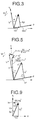
- Fig. 2 is a detailed block diagram for detection of inverter output power in Fig. 1;
- Fig. 3 is a vector diagram of the primary voltage and current shown in Fig. 2;
- Fig. 4 is a block diagram of another embodiment for detecting the inverter output power;
- Fig. 5 is a vector diagram of the primary voltage and current shown in Fig. 4;
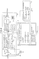
- Fig. 6 is a block diagram showing a second embodiment of the present invention;
- Fig. 7 is a detailed block diagram for detection of inverter output power in the second embodiment;
- Fig. 8 is a block diagram for detection of the source voltage;
- Fig. 9 is a vector diagram of the voltage and current in the converter side of Fig. 8;
- Figs. 10 and 11 are block diagrams showing third and fourth embodiments of the present invention, respectively;
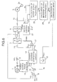
- Fig. 12 is a blockdiagram showing a fifth embodiment of the present invention;
- Fig. 13 is a block diagram of an inverter controller;
- Fig. 14 is a block diagram showing a sixth embodiment of the present invention;
- Fig. 15 is a block diagram showing a seventh embodiment of the present invention; and
- Fig. 16 is a block diagram showing an eighth embodiment of the present invention.
- Hereinafter, illustrated embodiments of the present invention will be described in detail. Throughout the embodiments, those elements having the same functions are denoted by the same reference characters.
- To begin with, a first embodiment of the present invention will be explained below with reference to the drawings.
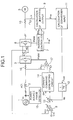
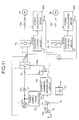
- In Fig. 1, AC power from an
AC power source 1 is supplied via areactor 2 to aconverter 3 where the AC power is transformed to DC power to be supplied to asmoothing capacitor 4 and aninverter 6. Theinverter 6 transforms the DC power from theconverter 3 to three-phase AC power for supplying it to anAC motor 5. Theconverter 3 is controlled by a PWM signal from acurrent controller 17, and theinverter 6 is controlled by a PWM signal from aninverter controller 7. - The
converter 3 is controlled as follows. Avoltage compensator 8 produces a current command value Iqc* corresponding to the deviation between a detected output of avoltage detector 40 for detecting the voltage across thesmoothing capacitor 4 and a DC voltage command value VDC*. The produced current command value and a source current value IqL are added in anadder 13 to produce a source current command value lq*. From this amplitude command and thephase angle 8R detected by asource phase detector 15, acurrent command generator 14 outputs a three-phase AC current command i*. Then, thecurrent controller 17 produces a PWM signal for controlling the deviation between the three-phase AC current command and a current i detected by acurrent detector 16 at the converter input side so as to become zero, and the PWM signal is used to control theconverter 3. Thus, theconverter 3 is controlled in accordance with the PWM signal such that the three-phase AC current command i* and the actual current i coincide with each other. The three-phase AC current command i* is calculated from a phase angle θR in the R phase and the amplitude command Iq* using the equations (1) - (3) below:


- Meanwhile, the
inverter 6 is controlled by a PWM signal from theinverter controller 7 in accordance with a primary frequency command ω1*. The source current value IqL is calculated byarithmetic sections gain 12 based on currents iu, iv detected by acurrent detector 10 and the magnitude V1* and phase θv1* of a primary voltage command outputted from theinverter controller 7. - To put it in more detail, as shown in Fig. 2, the
inverter controller 7 comprises anintegrator 18, aVF pattern generator 19, avoltage command generator 20, atriangular wave generator 21, and acomparator 22. In accordance with the primary frequency command ω1 *, theVf pattern generator 19 outputs a command V1* indicating the magnitude of the primaryvol- tage command. Theintegrator 18 integrates the primary frequency command ω1* to produce the phase θv1*. Then, a modulated wave is produced from V1* and θv1* using the equations (4) - (6) below, and compared with a triangular wave in thecomparator 22. The PWM signal is outputted from the compared result.


- The phase θv1* and the primary voltage magnitude command V1 * produced by the
inverter controller 7 are also supplied to thearithmetic section 9. - The
arithmetic section 9 calculates an output power of theinverter 6 based on the currents in the U and V phases detected by thecurrent detector 10, and the phase θv1* and the command V1* from theinverter controller 7. - Here, vectors of the primary voltage V1* and the primary current 11 look like as shown Fig. 3, and the angle formed between V1* and 11 gives a power-factor angle ψ. Assuming that the V1* vector extends in the direction of the q1 axis and the axis delayed 90° from the q1 axis is represented by the d1 axis, the component ld1 of the primary current 11 in the direction of the d1 axis is expressed by the following equation (7) and the component lq1 thereof in the direction of the q1 axis is expressed by the following equation (8), respectively;


- Therefore, the
actual magnitude 11 of the primary current, the power-factor angle ψ, and the inverter output power PINV for one phase are expressed by the following equations (9) - (11), respectively:


- Notice that when the DC voltage VDC fluctuates to a large extent, V1* is modified in proportion to VDC. In other words, the equation (11) may be rewritten by;
- PINV = KV · VDC · V1 * ' lq1
- The power calculated by the
arithmetic section 9 is supplied to thearithmetic section 11 which calculates an input power for theconverter 3. This power calculation is performed using the equations (12) and (13) below:

inverter 6 and theconverter 3 has the efficiency of 90 %, for example, K1 = 1.11 is selected. During a regenerating period of PINV < 0, there is PCNV < PINV. In this case, K2 = 0.9 is selected. Thus, the converter input power is calculated by selecting the constant K1 or K2 dependent on the sign of PINV, i.e., whether it is positive or negative, respectively. Notice that when the loss occuring in the converter and inverter section is small, thearithmetic section 11 can be dispensed with. The converter input power calculated by thearithmetic section 11 is divided by the source voltage Ve of the AC power source in thegain 12 to produce the source current value IqL. - Assuming now that the inverter output power for one phase under a torque of 2 kg - m is 900 W and the main circuit of the
inverter 6 and theconverter 3 has the efficiency of 90 %, the converter input power for one phase is determined to be 900 W/0.9 = 1000 W. Assuming the source voltage Ve to be 100 V, 10 A is determined from PCNV/Ve as the source current value dependent on the load. Then, by adding this source current value to the current command value Iqc* which has been compensated dependent on the deviation in the DC voltage, fluctuations in the output voltage of theconverter 3 can be prevented. - As described above, in this embodiment, the inverter output power is determined from the value of an electric variable in the output side of the
inverter 6 that undergoes very small ripple components, and the converter input power is determined from the inverter output power. The converter input power is divided by the source voltage to produce the source current value IqL which is added to the current command value Iqc* to obtain the final source current command value Iq*. Therefore, even when the load of themotor 5 is fluctuated abruptly, an AC current can be let flow into theconverter 3 in accordance with the fluctuations, thereby making it possible to suppress fluctuations in the output voltage of theconverter 3 and prevent the torque of themotor 5 from fluctuating. - In a steady state where the load torque of the
motor 5 is constant, since the source current value IqL based on the inverter output power and the load also becomes constant, the amplitude command value Iq* is kept almost constant so that a sinusoidal source current with the power-factor of 1 and small low-order higher components can be obtained. Although the command value V1 has been used as the magnitude of the primary voltage, it is alternatively possible to detect the output voltage of theinverter 6, and determine the inverter output power from the detected voltage, the motor current in the vector direction of primary voltage of theinverter 6 or the output current thereof, and the power-factor angle. - Next, an embodiment for calculating the inverter output power in a system which employs vector control of the voltage control type will be described with reference to Figs. 4 and 5.
- In this embodiment, the deviation between a rotational speed ωr outputted from a
speed detector 24 for detecting a rotational speed of themotor 5 and a speed command ωr* is compensated by a proportional andintegral compensator 25 to produce a torque current command It*. Based on this torque current command It* and an exciting current command lm*, avector calculator 26 calculates the magnitude V1* andphase angle 81 of the primary voltage. The output power of theinverter 6 is determined in thearithmetic section 9 from lm*, It*, V1* and 81. - In this connection, the
vector calculator 26 calculates V1*, 81 using the equations (14) - (17) below;


motor 5, l1, l2 are the primary and secondary leakage inductances, respectively, and M is the mutual inductance. - Further, as shown in Fig. 5, the magnitude I* and power-factor angle ψ of the primary current command are calculated from the following equations (18), (19), respectively, and the inverter output power for one phase is calculated from the following equation (20):


- In the embodiment, without detecting the current in the output side of the
inverter 6, the output power of theinverter 6 can be determined from the exciting current command lm*, the torque current command It*, and the constants of themotor 5. By determining the source current value IqL from the inverter output power, there can be obtained the similar advantageous effect as that in the above embodiment. - Next, a second embodiment for detecting the source current value IqL corresponding to the load from the output power of the
motor 5 will be described with reference to Figs. 6 and 7. - This embodiment is different from the embodiment of Fig. 1 in that an
inverter controller 27 is used instead of theinverter controller 7,arithmetic sections arithmetic sections - The
inverter controller 27 comprises a proportional andintegral compensator 25, acurrent vector calculator 30, anintegrator 18, acurrent command generator 31, ahysteresis comparator 32 and so on. Themagnitude 1* and phase △θ of the primary current are determined from the exciting current command lm* and the torque current command It*. Based on these values and an output signal of theintegrator 18, thecurrent command generator 31 outputs an AC current command i*, and a PWM signal is applied to theinverter 6 for controlling it such that the AC current command i* coincides with the actual current i. - On the other hand, the
arithmetic section 28 calculates the output power PM of themotor 5 from lm*, It*, ωr following the equation (21) below:
- Instead of using the command values Im*, It*, actual values lm, It can be determined from the following equations (22), (23), respectively,


- In the
arithmetic section 29, the output power of theinverter 6 is determined using the equation (24) below;
motor 5, for example, 1.43 for an efficiency of 70 %. - The inverter output power PINV calculated by the
arithmetic section 29 is applied to thearithmetic section 11 which determines the converter input power in a like manner to the foregoing embodiments. With this embodiment, there can be obtained the similar advantageous effect as that in the foregoing embodiments. - Next, an embodiment for detecting the actual source voltage Ve instead of the source phase voltage Ve set in the
gain 12 will be described with reference to Fig. 8. - Where the source voltage VR and the source current IR are controlled to have the same phase (power-factor 1), the voltage vector of the
converter 3 is represented as shown in Fig. 9. Assuming that the VR direction is given by the q axis and the axis delayed 90° from the q axis is given by the d axis, the d-axis component Id and q-axis component Iq of the primary current IR can be detected from currents iR, is of the R and S phases in the input side of theconverter 3. In this embodiment, therefore, acurrent detector 33 detects the components ld, Iq from the currents iR, is. Based on the detected outputs, proportional andintegral compensators gain 12. This permits a more accurate determination of the source current value IqL dependent on the load. - Moreover, Vy*, Vx* are processed in a
voltage vector calculator 35 such that the primary voltage vector command Vc* is converted to the phase 8c, which is further converted to an AC voltage command V* through a phasevoltage command generator 36. Afterward, the AC voltage command V* is compared with a triangular wave signal in acomparator 38, and the compared result is supplied as a PWM signal to theconverter 3. - Next, in a third embodiment shown in Fig. 10, a DC voltage compensator BAfor compensating for the deviation between the detected output of the
voltage detector 40 and the DC voltage command VDC* outputs a power commande value Pqc*. This power command value is added in anadder 13A to the calculated power PCNV from thearithmetic section 11 to determine the added power value Pq*. This added power value Pq* is divided by the source voltage in thegain 12, and the source current command value lq* is produced from the divided value. With this embodiment, there can also be obtained the similar advantageous effect as that in the foregoing embodiments. - In a fourth embodiment, shown in Fig. 11, adapted for a system where a plurality of
inverters converter 3 andmotors inverters arithmetic sections inverters adder 41. Then, by dividing the total power by the source voltage Ve in thegain 12, the source current value IqL is calculated as a current value necessary for the plurality ofAC motors converter 3 and prevent the loads of the respective motors from fluctuating. - As described above, in the foregoing four embodiments of the present invention, the output power of the inverter is determined based on the value of an electric variable in the inverter output side, the input power of the converter is determined from the output power of the inverter, the resulting input power of the converter is divided by the source voltage to produce a source current value dependent on the load, and this source current value is added to a source current value compensated dependent on the deviation in the DC voltage for providing the final source current amplitude command. Accordingly, in response to abrupt fluctuations in the load, the source current dependent on such fluctuations in the load can be let promptly flow into the converter. As a result, it is possible to suppress fluctuations in the output voltage of the converter and prevent the torque of the motor from fluctuating. Furthermore, in a steady state where the load torque of the motor is constant, since the current source value dependent on the load also becomes constant, the source current with the power-factor of 1 and small low-order higher components can be obtained.
- A fifth embodiment of the present invention will be described below with reference to the drawings.
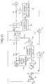
- In Fig. 12, AC power from an
AC power source 1 is supplied via areactor 2 to aconverter 3 where the AC power is transformed to DC power to be supplied to a smoothingcapacitor 4 and aninverter 6. Theinverter 6 transforms the DC power from theconverter 3 to three-phase AC power for supplying it to anAC motor 5. Theconverter 3 is controlled by a PWM signal from acurrent controller 181, and theinverter 6 is controlled by a PWM signal from aninverter controller 7. - The
converter 3 is controlled as follows. Avoltage compensator 8 produces a current command value △Iq* corresponding to the deviation between a detected output of avoltage detector 251 for detecting the voltage across the smoothingcapacitor 4 and a DC voltage command VDC*. The produced current command value and a source current value IqL are added in anadder 13 to produce a source current command value lq* through alimiter 141. From this amplitude command and the phase angle θR detected by asource phase detector 161, acurrent command generator 151 outputs a three-phase AC current command i*. Then, thecurrent controller 181 produces a PWM signal for controlling the deviation between the three-phase AC current command and a current i detected by acurrent detector 171 in the converter input side so as to become zero, and the PWM signal is used to control theconverter 3. Thus, theconverter 3 is controlled in accordance with the PWM signal such that the three-phase AC current command i* and the actual current i coincide with each other. The three-phase AC current command i* is calculated from a phase angle θR in the R phase and the amplitude command lq* using the equations (101)-(103) below:


- Meanwhile, the
inverter 6 is controlled by a PWM signal from theinverter controller 7 in accordance with a primary frequency command f1*. The source current value IqL is calculated by anarithmetic section 9, comprising a microcomputer, amultiplier 111 and again 121 based on currents iu, iv detected by acurrent detector 10 and a penetration factor δ (8u, 8v, 8w) outputted from theinverter controller 7. - As shown in Fig. 13, the
inverter controller 7 comprises anintegrator 191, a KH/f1* pattern generator 201, a modulatedwave command generator 211, atriangular wave generator 221, a comparator 231, and apenetration factor calculator 241. When frequency command f1* is applied to theintegrator 191 and thepattern generator 201, thepattern generator 201 outputs a command KH for the amplitude ratio of a modulated wave M* corresponding to the magnitude of the primary voltage, and theintegrator 191 outputs aphase command 0* obtained by integrating the frequency command f1*. Upon those output commands being applied to the modulatedwave command generator 211, modulated wave commands for the respective phases are produced using the equations (104) - (106) below;


wave command generator 211, they are compared in the comparator 231 with a triangular wave signal (1 - 2 kHz) from thetriangular wave generator 221 for each carrier cycle Tc of the triangular wave. As a result, the comparator 231 outputs the PWM signal. On the other hand, the modulated waves M* applied to thepenetration factor calculator 241 are used to calculate the penetration factors using the equations (107) - (109) below;


penetration factor 8 denotes a rate of turning-on time of a pulse signal for each phase during the carrier cycle Tc, and usually has a value in a range of 0 ≦ δ ≦ 1. - The penetration factors δ calculated by the
calculator 241 are applied to thearithmetic section 9 which calculates an inverter input average current I DC from the penetration factors and the detected currents from thecurrent detector 10 using the equation (110) below:
inverter 6 and the AC current for each phase in the inverter output side, and totaling the respective multiplied values in accordance with the equation (110), the resultant current is equivalent to the inverter input average current. In other words, on the assumption that the input current of themotor 5 hardly changes during the carrier cycle Tc, the average input current of theinverter 6 is determined from the equation (110) in this embodiment. - In addition, the penetration factors δ are generally given by the following equations (111) - (113), and the above equations (107) - (109) are used in PWM modulation of sinusoidal waves:


- Thus, the inverter input average current gives a current resulted from averaging the input current of the inverter during the carrier cycle Tc, and can be used as a DC current with less ripple components. AI- though IDC is determined from the penetration factors for each carrier cycle using the equation (110) in this embodiment, it can also be similarly determined from penetration factors for any period which is an integer multiple of the carrier half-cycle Tc/2.
- Moreover, the (0, 0, 0) and (1, 1, 1) regions of a three-phase PWM signal are generally called zero voltage vector regions in which there flows no inverter input current. In view of this, the inverter input average current can further be determined from penetrations factors for any region excepting those zero voltage vector regions.
- The inverter input average current I DC calculated by the
arithmetic section 9 is multiplied in themultiplier 111 by the detected voltage VDC from avoltage detector 251 for detecting the input voltage of theinverter 6, thereby to calculate inverter input average power PL. This calculated power PL is divided in thegain 121 by the source voltage 3Ve of theAC power source 1 for conversion to the source current value IqL. Because the inverter input average current I DC is a value with less ripple components and is detected instantaneously, controlling theconverter 3 in accordance with the source current value IqL results in that, even when the load of theinverter 6 is fluctuated abruptly, it is possible to flow the source current into theinverter 3 dependent on such fluctuations in the load, and to suppress fluctuations in the DC voltage of theconverter 3 and hence in the torque of themotor 5. Furthermore, since the calculated power PL has small ripple components, the source current value IqL is also kept almost constant, whereby the source current amplitude command lq* can be maintained substantially constant and the sinusoidal source current with a power-factor of 1 and small low-order higher components can be obtained. - Alternatively, as shown in a sixth embodiment of Fig. 14, it is also feasible to insert the
gain 121 between theadder 13 and thelimiter 141, apply the output of themultiplier 111 to theadder 13, and employ thevoltage compensator 8 as means for producing a power command value. More specifically, thevoltage compensator 8 compares the detected DC voltage VDC with the DC voltage command VDC* to produce a power command value △Pq for restraining the deviation therebetween so as to become zero. This power command value 4Pq is added to the inverter input average power PL in theadder 13 which outputs a summed power command value Pq. Then, the power command value Pq is divided by the source voltage in thegain 121, and the resultant value is produced as the source current command value lq* through thelimiter 141. - With this embodiment, there can also be obtained the similar advantageous effect as that in the foregoing embodiments.
- Next, in a seventh embodiment shown in Fig. 15, a
multiplier 261 is used instead of thegain 121 to multiply the inverter input average currentby the DC voltage command VDC* and divide the resultant power by the AC voltage Ve of the
AC power source 1, thereby calculating the source current value IqL. This embodiment can also provide the similar advantageous effect as that in the foregoing embodiments. In this case, approximate load compensation can be performed by assuming the relationship of the DC voltage command VDC = the input voltage VDC of theinverter 6. - An eighth embodiment in which a plurality of inverters are connected to a single converter in parallel will be described below with reference to Fig. 16.
-
Smoothing capacitors 4A - 4N andinverters 6A-6N are connected to the output side of theconverter 3 in parallel, andAC motors 5A- 5N are connected to respective outputs of theinverters 6A - 6N.Current detectors 10A- 10N are associated with theinverters 6A - 6N on the output side thereof, and the inverters are further provided withinverter controllers 7A - 7N and arithmetic sections 9A - 9N, respectively. Then, outputs of the arithmetic sections 9A- 9N are applied to anadder 271. - In this embodiment, the arithmetic sections 9A-9N calculate inverter input average currents

inverters 6A- 6N, and these calculated values are added to each other in theadder 271 to determine an inverter input average value of the entire inverter. Then, an output current IDC of theadder 271 is applied to amultiplier 111 for determining input power PL of the entire inverter. - With this embodiment, too, even when torques of the
AC motors 5A- 5N are fluctuated, the source current dependent on such fluctuations is let to promptly flow into theconverter 3, making it possible to suppress torque fluctuations of the respective AC motors and supply the sinusoidal source current to theconverter 3, like the above embodiment. - The above-described embodiments are described in relation to an apparatus for PWM-controlling the converters so as to make an actual current of the power source follow the current command of the A.C. power source, but are not limited there to. For example the apparatus may be a conventional apparatus for controlling a converter with a direct current. In other words, the apparatus may be an apparatus for PWM-controlling the converter with a direct current so as to make Id = 0 and Iq* = Iq (refer to Fig. 1) based on detection Id of which is a component delayed 90° to the effective current Iq which is a component of the power source voltage vector.
- In the foregoing embodiments, since the inverter input average current can be determined without detecting the input current of the
inverter 6, the current detector for detecting the current in the input side of theinverter 6 can be dispensed with, which contributes to a reduction of the cost. - Further, since the method of detecting the inverter input average current according to the present invention enables an instantaneous detection of the inverter input current as a DC quantity, it can be used to implement a detector not only for converter control, but also for other various types of control of motors. For instance, the method may be used to suppress vibrations of induction motors under a small load.
- As described above, with the fifth to eighth embodiments of the present invention, the current equivalent to the inverter input average current is determined from the output current of the inverter, and the converter is controlled in accordance with the determined current value. Therefore, even upon the load being changed abruptly, the source current dependent on fluctuations in the load can be allowed to promptly flow into the converter, thereby making it possible to suppress fluctuations in the output voltage of the converter and in the torque of the motor. Moreover, since the inverter input power is calculated from the inverter input average current, the source current value dependent on fluctuations in the load becomes a constant DC quantity, whereby the sinusoidal source current with a power-factor of 1 and small low-order higher components can be supplied to the converter.
where Kv is a constant determined dependent on the reference of VDC.
Claims (25)
characterized in further comprising the steps of
characterized in that
characterized in that
characterized in that
in the step of calculating the inverter power the inverter output power is calculated also based on the detected rotational speed.
characterized in that
characterized in that
characterized in that
in the step of calculating the inverter power the average input current of the inverter is calculated also based on a penetration factor of a pulse signal used in controlling the inverter, the penetration factor being determined over a period equal to an integer multiple of a half-cycle of a periodic signal used in controlling the inverter.
characterized in that
characterized in that
characterized in that
characterized in that
characterized in further comprising
characterized in further comprising
characterized in that
characterized in that
characterized in that
the means for calculating the inverter power calculates the output power of the inverter also based on the detected rotational speed.
characterized in that
characterized in that
characterized in that
the means for detecting an operational parameter of the AC motor system includes means for detecting an output current of the inverter, and in the means for calculating the inverter power the means for calculating an average input current of the inverter calculate it also based on a penetration factor of a pulse signal used in controlling the inverter, the penetration factor being determined over a period equal to an integer multiple of a half-cycle of a periodic signal used in controlling the inverter.
characterized in that
characterized in that
characterized in that
characterized in that
characterized in that
Applications Claiming Priority (6)
| Application Number | Priority Date | Filing Date | Title |
|---|---|---|---|
| JP238446/89 | 1989-09-14 | ||
| JP23844689 | 1989-09-14 | ||
| JP42783/90 | 1990-02-23 | ||
| JP2042783A JP2955716B2 (en) | 1990-02-23 | 1990-02-23 | AC motor control method and device |
| JP115516/90 | 1990-05-01 | ||
| JP2115516A JP2946106B2 (en) | 1989-09-14 | 1990-05-01 | AC motor control method and device |
Publications (2)
| Publication Number | Publication Date |
|---|---|
| EP0417805A1 EP0417805A1 (en) | 1991-03-20 |
| EP0417805B1 true EP0417805B1 (en) | 1995-05-24 |
Family
ID=27291346
Family Applications (1)
| Application Number | Title | Priority Date | Filing Date |
|---|---|---|---|
| EP90117738A Expired - Lifetime EP0417805B1 (en) | 1989-09-14 | 1990-09-14 | Control method and device for AC motor |
Country Status (3)
| Country | Link |
|---|---|
| US (1) | US5184057A (en) |
| EP (1) | EP0417805B1 (en) |
| DE (1) | DE69019645T2 (en) |
Families Citing this family (31)
| Publication number | Priority date | Publication date | Assignee | Title |
|---|---|---|---|---|
| WO1995002921A1 (en) * | 1992-01-17 | 1995-01-26 | Kabushiki Kaisha Meidensha | Apparatus and method for controlling current of variable speed driver |
| JPH0638575A (en) * | 1992-07-17 | 1994-02-10 | Honda Motor Co Ltd | Torque controller for alternating current motor |
| JP3286854B2 (en) * | 1992-10-27 | 2002-05-27 | 松下電器産業株式会社 | Motor drive device |
| US5349278A (en) * | 1993-05-13 | 1994-09-20 | Hughes Aircraft Company | Torque oscillation compensation utilizing velocity feedback |
| US5350989A (en) * | 1993-05-13 | 1994-09-27 | Hughes Aircraft Company | Torque oscillation compensation utilizing battery current sensing |
| IT1263572B (en) * | 1993-05-31 | 1996-08-27 | Merloni Antonio Spa | "METHOD OF REALIZATION OF A THREE-PHASE ELECTRONIC INVERTER DELIVERING A VARIABLE VOLTAGE ACCORDING TO THE GENERATED FREQUENCY" |
| FR2714234B1 (en) * | 1993-12-16 | 1996-08-23 | Telemecanique | Power control system for an asynchronous motor. |
| US5428283A (en) * | 1994-05-26 | 1995-06-27 | Alliedsignal Inc. | Power factor control of pulse width modulated inverter supplied permanent magnet motor |
| JPH0835713A (en) * | 1994-07-26 | 1996-02-06 | Fujitsu General Ltd | Method and apparatus for controlling air conditioner |
| JP3295553B2 (en) * | 1994-10-05 | 2002-06-24 | 三菱電機株式会社 | Variable speed device |
| DE19519759C2 (en) * | 1995-05-30 | 1999-04-15 | Siemens Ag | Power converter |
| DE19634449C2 (en) * | 1996-08-26 | 1998-07-09 | Brueckner Maschbau | Control device for linear motor-driven devices |
| AT408296B (en) * | 1997-02-27 | 2001-10-25 | Elin Ebg Traction Gmbh | Method for regulating the input current of a four- quadrant mains converter, which is fed from the single- phase AC mains system, of a voltage intermediate-circuit converter |
| US6337803B2 (en) * | 1999-06-24 | 2002-01-08 | Nissan Motor Co., Ltd. | Power module |
| JP3789843B2 (en) * | 2002-03-29 | 2006-06-28 | 三洋電機株式会社 | Method for controlling rotational speed of brushless motor and washing machine using the same |
| JP4304122B2 (en) * | 2004-05-25 | 2009-07-29 | 三菱電機株式会社 | Electric vehicle control device |
| US7102326B1 (en) * | 2005-08-08 | 2006-09-05 | Fego Precision Industrial Co., Ltd. | Motor speed variator and a driving method thereof |
| US8657585B2 (en) * | 2010-02-08 | 2014-02-25 | Lg Electronics Inc. | Apparatus for driving compressor of air conditioner and method for driving the same |
| US8278850B2 (en) * | 2010-03-09 | 2012-10-02 | GM Global Technology Operations LLC | Methods, systems and apparatus for optimization of third harmonic current injection in a multi-phase machine |
| CN102381594B (en) * | 2010-08-31 | 2014-02-26 | 上海三菱电梯有限公司 | Energy saving device for elevators |
| KR101621994B1 (en) * | 2011-12-30 | 2016-05-17 | 엘에스산전 주식회사 | Control apparatus for regenerative medium voltage inverter |
| US9973130B2 (en) * | 2016-02-17 | 2018-05-15 | Ghing-Hsin Dien | Method for driving an AC motor by two-phase electric power and power generation method |
| JP6390649B2 (en) * | 2016-03-18 | 2018-09-19 | 株式会社安川電機 | Power converter, motor power estimation method and motor control method |
| ITUA20162878A1 (en) * | 2016-04-26 | 2017-10-26 | Phase Motion Control S P A | POWER AND DRIVE DEVICE FOR A PERMANENT MAGNET ELECTRIC MOTOR |
| JP2018023178A (en) * | 2016-08-01 | 2018-02-08 | 株式会社日立製作所 | Power converter control device, compressor driving system, flywheel power generation system, and power converter control method |
| JP2018088798A (en) * | 2016-11-30 | 2018-06-07 | 三菱重工サーマルシステムズ株式会社 | Motor control device, motor control method, program, and phase adjustment method |
| JP2018088797A (en) * | 2016-11-30 | 2018-06-07 | 三菱重工サーマルシステムズ株式会社 | Motor control device, motor control method, program, and phase adjustment method |
| JP6658554B2 (en) * | 2017-01-10 | 2020-03-04 | 株式会社デンソー | AC motor control device |
| KR101739929B1 (en) * | 2017-03-10 | 2017-05-26 | (주) 한사 | Motor control device controlling several motors independently |
| DE102017125317A1 (en) * | 2017-10-27 | 2019-05-02 | Ebm-Papst Mulfingen Gmbh & Co. Kg | Multi-motor operation |
| US11881803B2 (en) * | 2021-01-15 | 2024-01-23 | Toyota Jidosha Kabushiki Kaisha | Control device for electric vehicle |
Family Cites Families (9)
| Publication number | Priority date | Publication date | Assignee | Title |
|---|---|---|---|---|
| JPS5513151B2 (en) * | 1972-11-10 | 1980-04-07 | ||
| JPS5594583A (en) * | 1979-01-10 | 1980-07-18 | Hitachi Ltd | Frequency converter and its controlling method |
| JPS5783194A (en) * | 1980-11-10 | 1982-05-24 | Hitachi Ltd | Ac motor controlling device using pulse width modulation inverter |
| DE3151904C2 (en) * | 1981-12-30 | 1985-12-12 | Uranit GmbH, 5170 Jülich | Method for optimizing the power consumption of a large number of hysteresis motors connected in parallel |
| DE3241828A1 (en) * | 1982-11-09 | 1984-05-10 | Licentia Patent-Verwaltungs-Gmbh, 6000 Frankfurt | Method for suppressing harmonics in the output voltage of a converter |
| CA1224245A (en) * | 1984-03-02 | 1987-07-14 | Suzuo Saito | Power converter for ac load |
| JPS61109491A (en) * | 1984-10-31 | 1986-05-27 | Mitsubishi Electric Corp | Motor controller |
| DE3527844A1 (en) * | 1985-07-31 | 1987-02-12 | Licentia Gmbh | Circuit arrangement for frequency adjustment of a DC voltage intermediate-circuit converter with a constant output voltage |
| JPH02299471A (en) * | 1989-05-12 | 1990-12-11 | Mitsubishi Electric Corp | Controlling method for pwm converter |
-
1990
- 1990-09-13 US US07/581,898 patent/US5184057A/en not_active Expired - Lifetime
- 1990-09-14 EP EP90117738A patent/EP0417805B1/en not_active Expired - Lifetime
- 1990-09-14 DE DE69019645T patent/DE69019645T2/en not_active Expired - Fee Related
Also Published As
| Publication number | Publication date |
|---|---|
| EP0417805A1 (en) | 1991-03-20 |
| DE69019645D1 (en) | 1995-06-29 |
| DE69019645T2 (en) | 1995-09-21 |
| US5184057A (en) | 1993-02-02 |
Similar Documents
| Publication | Publication Date | Title |
|---|---|---|
| EP0417805B1 (en) | Control method and device for AC motor | |
| EP0293915B1 (en) | Inverter control apparatus | |
| EP2043241B1 (en) | Motor Drive Using Flux Adjustment to Control Power Factor | |
| RU2392732C1 (en) | Device for control of asynchronous motor vector, method for control of asynchronous motor vector and device for control of asynchronous motor drive | |
| EP1100191B1 (en) | Inverter control apparatus and method for controlling an inverter | |
| EP0082303B1 (en) | Method and apparatus for controlling induction motor | |
| AU713034B2 (en) | Multilevel power converting apparatus | |
| US4800327A (en) | Three-phase induction motor control method | |
| EP0579513B1 (en) | Torque control system for AC motor | |
| US5400240A (en) | Power converter apparatus | |
| US4785225A (en) | Control apparatus for an induction motor | |
| EP0536569A2 (en) | AC motor control apparatus and control apparatus of electric rolling stock using the same | |
| RU2193814C2 (en) | Control gear and method for controlling induction motor | |
| JPH0344508B2 (en) | ||
| JP3236985B2 (en) | Control device for PWM converter | |
| JP3381465B2 (en) | Control method of power converter | |
| JP2946106B2 (en) | AC motor control method and device | |
| JP3323759B2 (en) | Pulse width modulation converter device | |
| JP2955716B2 (en) | AC motor control method and device | |
| JPH0783599B2 (en) | Control method of circulating current type cycloconverter | |
| EP0237012B1 (en) | A control apparatus for pwm power converters | |
| JP2702936B2 (en) | Method and apparatus for controlling voltage source inverter | |
| JP2638801B2 (en) | Method and apparatus for controlling induction motor system | |
| JP3323901B2 (en) | Control device for linear motor electric vehicle | |
| JP3302854B2 (en) | Induction motor control device |
Legal Events
| Date | Code | Title | Description |
|---|---|---|---|
| PUAI | Public reference made under article 153(3) epc to a published international application that has entered the european phase |
Free format text: ORIGINAL CODE: 0009012 |
|
| AK | Designated contracting states |
Kind code of ref document: A1 Designated state(s): DE FR GB IT |
|
| 17P | Request for examination filed |
Effective date: 19910911 |
|
| 17Q | First examination report despatched |
Effective date: 19930617 |
|
| GRAA | (expected) grant |
Free format text: ORIGINAL CODE: 0009210 |
|
| AK | Designated contracting states |
Kind code of ref document: B1 Designated state(s): DE FR GB IT |
|
| REF | Corresponds to: |
Ref document number: 69019645 Country of ref document: DE Date of ref document: 19950629 |
|
| ITF | It: translation for a ep patent filed |
Owner name: MODIANO & ASSOCIATI S.R.L. |
|
| ET | Fr: translation filed | ||
| PLBE | No opposition filed within time limit |
Free format text: ORIGINAL CODE: 0009261 |
|
| STAA | Information on the status of an ep patent application or granted ep patent |
Free format text: STATUS: NO OPPOSITION FILED WITHIN TIME LIMIT |
|
| 26N | No opposition filed | ||
| PGFP | Annual fee paid to national office [announced via postgrant information from national office to epo] |
Ref country code: GB Payment date: 19990625 Year of fee payment: 10 |
|
| PG25 | Lapsed in a contracting state [announced via postgrant information from national office to epo] |
Ref country code: GB Free format text: LAPSE BECAUSE OF NON-PAYMENT OF DUE FEES Effective date: 20000914 |
|
| GBPC | Gb: european patent ceased through non-payment of renewal fee |
Effective date: 20000914 |
|
| PG25 | Lapsed in a contracting state [announced via postgrant information from national office to epo] |
Ref country code: IT Free format text: LAPSE BECAUSE OF NON-PAYMENT OF DUE FEES;WARNING: LAPSES OF ITALIAN PATENTS WITH EFFECTIVE DATE BEFORE 2007 MAY HAVE OCCURRED AT ANY TIME BEFORE 2007. THE CORRECT EFFECTIVE DATE MAY BE DIFFERENT FROM THE ONE RECORDED. Effective date: 20050914 |
|
| PGFP | Annual fee paid to national office [announced via postgrant information from national office to epo] |
Ref country code: FR Payment date: 20060814 Year of fee payment: 17 |
|
| PGFP | Annual fee paid to national office [announced via postgrant information from national office to epo] |
Ref country code: DE Payment date: 20060828 Year of fee payment: 17 |
|
| PG25 | Lapsed in a contracting state [announced via postgrant information from national office to epo] |
Ref country code: DE Free format text: LAPSE BECAUSE OF NON-PAYMENT OF DUE FEES Effective date: 20080401 |
|
| REG | Reference to a national code |
Ref country code: FR Ref legal event code: ST Effective date: 20080531 |
|
| PG25 | Lapsed in a contracting state [announced via postgrant information from national office to epo] |
Ref country code: FR Free format text: LAPSE BECAUSE OF NON-PAYMENT OF DUE FEES Effective date: 20071001 |