EP0361834A2 - Current source inverter control system for load cummutated induction motor drive - Google Patents
Current source inverter control system for load cummutated induction motor drive Download PDFInfo
- Publication number
- EP0361834A2 EP0361834A2 EP89309735A EP89309735A EP0361834A2 EP 0361834 A2 EP0361834 A2 EP 0361834A2 EP 89309735 A EP89309735 A EP 89309735A EP 89309735 A EP89309735 A EP 89309735A EP 0361834 A2 EP0361834 A2 EP 0361834A2
- Authority
- EP
- European Patent Office
- Prior art keywords
- motor
- inverter
- signal
- power factor
- line
- Prior art date
- Legal status (The legal status is an assumption and is not a legal conclusion. Google has not performed a legal analysis and makes no representation as to the accuracy of the status listed.)
- Withdrawn
Links
Images

Classifications
-
- H—ELECTRICITY
- H02—GENERATION; CONVERSION OR DISTRIBUTION OF ELECTRIC POWER
- H02M—APPARATUS FOR CONVERSION BETWEEN AC AND AC, BETWEEN AC AND DC, OR BETWEEN DC AND DC, AND FOR USE WITH MAINS OR SIMILAR POWER SUPPLY SYSTEMS; CONVERSION OF DC OR AC INPUT POWER INTO SURGE OUTPUT POWER; CONTROL OR REGULATION THEREOF
- H02M1/00—Details of apparatus for conversion
- H02M1/42—Circuits or arrangements for compensating for or adjusting power factor in converters or inverters
- H02M1/4208—Arrangements for improving power factor of AC input
-
- H—ELECTRICITY
- H02—GENERATION; CONVERSION OR DISTRIBUTION OF ELECTRIC POWER
- H02M—APPARATUS FOR CONVERSION BETWEEN AC AND AC, BETWEEN AC AND DC, OR BETWEEN DC AND DC, AND FOR USE WITH MAINS OR SIMILAR POWER SUPPLY SYSTEMS; CONVERSION OF DC OR AC INPUT POWER INTO SURGE OUTPUT POWER; CONTROL OR REGULATION THEREOF
- H02M5/00—Conversion of ac power input into ac power output, e.g. for change of voltage, for change of frequency, for change of number of phases
- H02M5/40—Conversion of ac power input into ac power output, e.g. for change of voltage, for change of frequency, for change of number of phases with intermediate conversion into dc
- H02M5/42—Conversion of ac power input into ac power output, e.g. for change of voltage, for change of frequency, for change of number of phases with intermediate conversion into dc by static converters
- H02M5/44—Conversion of ac power input into ac power output, e.g. for change of voltage, for change of frequency, for change of number of phases with intermediate conversion into dc by static converters using discharge tubes or semiconductor devices to convert the intermediate dc into ac
- H02M5/443—Conversion of ac power input into ac power output, e.g. for change of voltage, for change of frequency, for change of number of phases with intermediate conversion into dc by static converters using discharge tubes or semiconductor devices to convert the intermediate dc into ac using devices of a thyratron or thyristor type requiring extinguishing means
- H02M5/45—Conversion of ac power input into ac power output, e.g. for change of voltage, for change of frequency, for change of number of phases with intermediate conversion into dc by static converters using discharge tubes or semiconductor devices to convert the intermediate dc into ac using devices of a thyratron or thyristor type requiring extinguishing means using semiconductor devices only
- H02M5/4505—Conversion of ac power input into ac power output, e.g. for change of voltage, for change of frequency, for change of number of phases with intermediate conversion into dc by static converters using discharge tubes or semiconductor devices to convert the intermediate dc into ac using devices of a thyratron or thyristor type requiring extinguishing means using semiconductor devices only having a rectifier with controlled elements
-
- H—ELECTRICITY
- H02—GENERATION; CONVERSION OR DISTRIBUTION OF ELECTRIC POWER
- H02M—APPARATUS FOR CONVERSION BETWEEN AC AND AC, BETWEEN AC AND DC, OR BETWEEN DC AND DC, AND FOR USE WITH MAINS OR SIMILAR POWER SUPPLY SYSTEMS; CONVERSION OF DC OR AC INPUT POWER INTO SURGE OUTPUT POWER; CONTROL OR REGULATION THEREOF
- H02M5/00—Conversion of ac power input into ac power output, e.g. for change of voltage, for change of frequency, for change of number of phases
- H02M5/40—Conversion of ac power input into ac power output, e.g. for change of voltage, for change of frequency, for change of number of phases with intermediate conversion into dc
- H02M5/42—Conversion of ac power input into ac power output, e.g. for change of voltage, for change of frequency, for change of number of phases with intermediate conversion into dc by static converters
- H02M5/44—Conversion of ac power input into ac power output, e.g. for change of voltage, for change of frequency, for change of number of phases with intermediate conversion into dc by static converters using discharge tubes or semiconductor devices to convert the intermediate dc into ac
- H02M5/453—Conversion of ac power input into ac power output, e.g. for change of voltage, for change of frequency, for change of number of phases with intermediate conversion into dc by static converters using discharge tubes or semiconductor devices to convert the intermediate dc into ac using devices of a triode or transistor type requiring continuous application of a control signal
- H02M5/458—Conversion of ac power input into ac power output, e.g. for change of voltage, for change of frequency, for change of number of phases with intermediate conversion into dc by static converters using discharge tubes or semiconductor devices to convert the intermediate dc into ac using devices of a triode or transistor type requiring continuous application of a control signal using semiconductor devices only
- H02M5/4585—Conversion of ac power input into ac power output, e.g. for change of voltage, for change of frequency, for change of number of phases with intermediate conversion into dc by static converters using discharge tubes or semiconductor devices to convert the intermediate dc into ac using devices of a triode or transistor type requiring continuous application of a control signal using semiconductor devices only having a rectifier with controlled elements
-
- H—ELECTRICITY
- H02—GENERATION; CONVERSION OR DISTRIBUTION OF ELECTRIC POWER
- H02P—CONTROL OR REGULATION OF ELECTRIC MOTORS, ELECTRIC GENERATORS OR DYNAMO-ELECTRIC CONVERTERS; CONTROLLING TRANSFORMERS, REACTORS OR CHOKE COILS
- H02P25/00—Arrangements or methods for the control of AC motors characterised by the kind of AC motor or by structural details
- H02P25/02—Arrangements or methods for the control of AC motors characterised by the kind of AC motor or by structural details characterised by the kind of motor
- H02P25/022—Synchronous motors
- H02P25/024—Synchronous motors controlled by supply frequency
-
- Y—GENERAL TAGGING OF NEW TECHNOLOGICAL DEVELOPMENTS; GENERAL TAGGING OF CROSS-SECTIONAL TECHNOLOGIES SPANNING OVER SEVERAL SECTIONS OF THE IPC; TECHNICAL SUBJECTS COVERED BY FORMER USPC CROSS-REFERENCE ART COLLECTIONS [XRACs] AND DIGESTS
- Y02—TECHNOLOGIES OR APPLICATIONS FOR MITIGATION OR ADAPTATION AGAINST CLIMATE CHANGE
- Y02B—CLIMATE CHANGE MITIGATION TECHNOLOGIES RELATED TO BUILDINGS, e.g. HOUSING, HOUSE APPLIANCES OR RELATED END-USER APPLICATIONS
- Y02B70/00—Technologies for an efficient end-user side electric power management and consumption
- Y02B70/10—Technologies improving the efficiency by using switched-mode power supplies [SMPS], i.e. efficient power electronics conversion e.g. power factor correction or reduction of losses in power supplies or efficient standby modes
Definitions
- the invention relates to control of Load Commutated Inverter (LCI) induction motor drives.
- LCDI Load Commutated Inverter
- the invention resides in generating in response to a motor reference speed a signal representative of the desired power factor angle, and by using such power factor angle as a delay applied to the train of gating pulses normally used to control the inventor of a load commutated inverter induction motor drive.
- the induction motor behaves much like a synchronous motor as far as current source inverter (CSI) is concerned, for a significant speed range.
- CSI current source inverter
- the present invention bears upon the problem of stability encountered with a Load Commutated Inverter Induction Machine (LCI/IM) drive, i.e. one where the induction motor has a capacitor bank in parallel.
- LCI/IM Load Commutated Inverter Induction Machine
- the invention is based on the observation that, but for certain deviations which are minimal, the firing angle of the inverter in a CSI control loop is practically equal to the power factor angle on the output lines from the inverter to the load, i.e. the induction motor.
- FIG. 1 Referring to the conventional approach of CSI control as applied to a forced-commutation induction motor drive, the basic circuit is shown in Figure 1.
- the AC power lines PL are inputted into a converter CNV which connects with a DC-Link DCL .
- the DC-Link passes the DC current I onto an inverter INV generating AC power on output lines OL to the load.
- This is the well-known current-sourced inverter (CSI) which is supplying power to the induction motor MT at a frequency f determining the speed of the motor.
- the speed of the motor is controlled by a reference speed signal f* on line 10 actuating a variable frequency controlled oscillator (VCO) to produce a train of gating pulses GP at the imposed rate to the inverter.
- VCO variable frequency controlled oscillator
- the torque also depends upon the DC-link current I.
- the latter is controlled by controlling the converter firing angle ⁇ c on line 19 at the output of a P I controller (PIC) operated in accordance with the difference (at S3) between the reference speed (lines 10 and 11) and a feedback signal VM derived on line 2 after rectification at RCT of the line voltages sensed by lines 2 from the output lines OL of the inverter.
- the signal of line 12 is scaled at SK and the output thereof, on line 17, is compared (at S4) with a DC-Link current feedback signal (line 23), then, processed by the PI Controller (PI) so as to generate on line 19 a gating signal of desired firing angle ⁇ c for the converter CNV .
- This loop regulates the DC-Link current I.
- the current is regulated to achieve a desired voltage, i.e. to increase the current when the voltage is too low, and conversely when the voltage is too high, whereas (at S3) a constant voltage-to-frequency ratio is being maintained (as expressed by the reference current of line 17).
- FIG. 2 which shows a model of the current source inverter closed upon its load
- the current source with the current IS to the right is the motor with the reflected emf represented by the voltage Vm.
- Two parallel branches are in derivation, one capacitive C (from point A to point B), the other inductive Lm (from point C to point D), as generally known.
- Vm is proportional to motor speed and to the magnetizing current Im.
- the inverter produces the current source current Is which is independent of Vm.
- the inverter provide an imaginary component Is ( Figure 2A) such as to cancel the excessive magnetizing current from the system. This is equivalent to injecting the required amount of leading current into the system.
- the real component of Is is consumed by the motor to do work.
- the component which is critical in producing a stable system is the quadrature component Isq, related to Ic and Im.
- Isq Ic + Im (3)
- Isq Vm ( ⁇ C - [1/ ⁇ Lm]) (4)
- Vm is a function of motor speed
- Is is a function of motor load.
- Is is essentially constant. Therefore, given the motor speed, Vm and are known, and ⁇ is determined by the afore-stated function. More generally, in a given application such as flow control, Is can be predicted as a function of the imposed speed. In conclusion, ⁇ is determined as a function of the reference speed f*.
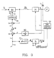
- the current source inverter (CSI) control for a Load Commutated Inverter Induction Motor (LCI/IM) drive is illustrated in block diagram as a direct modification of the circuit of Figure 2.
- a function generator FG is added responding to the reference frequency of lines 10 and 50 and outputting on line 51 a signal representative of the desired power factor angle ⁇ .
- the signal of line 51 is thereafter applied to a delay circuit DL which is interposed upon the series of pulses derived on line 53 from a zero-crossing detector (ZCD) having its input connected to the output lines OL of the inverter.
- ZCD zero-crossing detector
- the signal of line 51 insures that, whatever the load condition and the occurrence of the pulse of line 10 which is imposed by the frequency reference signal f*, firing will occur so that it matches the power factor angle, and the quadrature component of current will exist to prevent the runaway condition.
- the implementation of block FG is according to the afore-stated function F defining the angle ⁇ .
- the angle ⁇ is preprogrammed in a PROM as a function of the reference frequency f* addressing the PROM from line 50.
- the function so implemented is to impose an inverter firing instant that will cause the current impressed on the load to lead the voltage by ⁇ degrees.
- the power factor cos ⁇ is implemented by requiring a delay in the application of the gating pulses to the inverter, thereby forcing a quadrature component of the current to be formed which will reestablish a balance between the capacitive current and the magnetizing current within the current-sourced inverter model.
- the added loop including function generator FG and the power factor angle controlled delay DL, has been added to correct the train of inverter gating pulses, normally received from the zero-crossing detector ZCD by line 53.
Landscapes
- Engineering & Computer Science (AREA)
- Power Engineering (AREA)
- Control Of Ac Motors In General (AREA)
- Inverter Devices (AREA)
- Control Of Motors That Do Not Use Commutators (AREA)
Abstract
In a load commutated induction motor drive stability is achieved in a runaway situation by generating in response to the motor speed reference signal a signal representative of the desired power factor angle and in using such signal to delay by that much the gating pulses controlling the current-sourced inverter.
Description
- The invention relates to control of Load Commutated Inverter (LCI) induction motor drives.
- The invention resides in generating in response to a motor reference speed a signal representative of the desired power factor angle, and by using such power factor angle as a delay applied to the train of gating pulses normally used to control the inventor of a load commutated inverter induction motor drive.
- The problem of commutating the inverter thyristors, not encountered with a synchronous motor because of natural commutation, nor with an induction motor if the CSI control system includes forced-commutation, is solved with a LCI/IM drive by the use of a parallel capacitor bank. A problem of stability attaches to it.
- Load Commutated Inverter (LCI) Synchronous Motor Drives using a thyristor inverter bridge do not need forced commutation means, because automatic thyristor turn-off is achieved with a synchronous motor as the load, if it has a leading phase angle with respect to the load voltage. For a given load, increasing sufficiently the field will produce such leading power factor. See, for instance:
"The Synchronous Machine as a Self-Controlled Converter-Fed Motor" by Dieter Kollensperger in Siemens Review XXXV (1968) No. 5, pp. 195-201;
U.S. Patent No 4,713,743 of Dec. 15, 1987 (Alberto Abbondanti). - With an induction motor, however, this possibility no longer exists. The load power factor is lagging for all machine excitation levels. Therefore, specific circuitry must be used to allow a leading phase angle to take place, thereby providing natural commutation of the inverter bridge. To this effect, a general solution is to add a large capacitor bank in parallel with the motor so that the lagging load power factor be overcompensated, the net result being that leading VAR's are supplied to the composite load. Accordingly, the resultant leading power factor angle will insure natural commutation of the inverter poles. In such case, the motor drive is referred to as a Load Commutated Inverter Induction Machine (LCI/IM) drive. Thus, when the power factor of the induction motor has been overcompensated to produce a leading load power factor to a current source, in principle the induction motor behaves much like a synchronous motor as far as current source inverter (CSI) is concerned, for a significant speed range.
- Traditional Current Source Control (CSI) method, used where the inverter bridge includes thyristors and forced-commutation is applied for an induction motor drive, consists in regulating the DC-Link current magnitude in order to achieve the desired motor voltage. Motor speed is regulated by imposing the desired switching upon the inverter. The desired motor voltage is maintained proportional to the imposed frequency. This prior art approach, however, has revealed problems of stability, particularly encountered at low speed. One solution to this problem, as typified by U.S. Patent No. 4,602,198 of Herbert W. Weiss et al, has been to use in an LCI system a VAR generator in order to control the VAR supply. This is an expensive and complex approach to the problem.
- The present invention bears upon the problem of stability encountered with a Load Commutated Inverter Induction Machine (LCI/IM) drive, i.e. one where the induction motor has a capacitor bank in parallel. The invention is based on the observation that, but for certain deviations which are minimal, the firing angle of the inverter in a CSI control loop is practically equal to the power factor angle on the output lines from the inverter to the load, i.e. the induction motor.
- In order for the present invention to be easily understood and easily practiced, a preferred embodiment will be described, by way of example only, in conjunction with the accompanying drawings in which:
- Figure 1 shows in block diagram a typical CSI control for the converter and the inverter of a current source inverter as applied in the prior art to a motor, where natural commutation of the inverter is not required;
- Figure 2 is the model of a current source inverter;
- Figure 2A is a vectorial representation of the stator current and of its quadrature component relative to the emf vector of the motor in the case of the model of Figure 2;
- Figure 3 is a block diagram of the CSI control system according to the present invention, as can be used for a load commutated inverter (LCI) induction motor drive.
- Referring to the conventional approach of CSI control as applied to a forced-commutation induction motor drive, the basic circuit is shown in Figure 1. The AC power lines PL are inputted into a converter CNV which connects with a DC-Link DCL. The DC-Link passes the DC current I onto an inverter INV generating AC power on output lines OL to the load. This is the well-known current-sourced inverter (CSI) which is supplying power to the induction motor MT at a frequency f determining the speed of the motor. The speed of the motor is controlled by a reference speed signal f* on
line 10 actuating a variable frequency controlled oscillator (VCO) to produce a train of gating pulses GP at the imposed rate to the inverter. The torque also depends upon the DC-link current I. The latter is controlled by controlling the converter firing angle αc online 19 at the output of a P I controller (PIC) operated in accordance with the difference (at S3) between the reference speed (lines 10 and 11) and a feedback signal VM derived online 2 after rectification at RCT of the line voltages sensed bylines 2 from the output lines OL of the inverter. The signal ofline 12 is scaled at SK and the output thereof, online 17, is compared (at S4) with a DC-Link current feedback signal (line 23), then, processed by the PI Controller (PI) so as to generate on line 19 a gating signal of desired firing angle αc for the converter CNV. This loop regulates the DC-Link current I. The current is regulated to achieve a desired voltage, i.e. to increase the current when the voltage is too low, and conversely when the voltage is too high, whereas (at S3) a constant voltage-to-frequency ratio is being maintained (as expressed by the reference current of line 17). - When parallel capacitors are used for natural commutation (LCI approach) rather than forced-commutation, this method of CSI control becomes unsatisfactory. This is due to the self-exciting phenomenon of induction motors when parallel capacitors are present.
- Referring to Figure 2 which shows a model of the current source inverter closed upon its load, to the left is the current source with the current IS, to the right is the motor with the reflected emf represented by the voltage Vm. Two parallel branches are in derivation, one capacitive C (from point A to point B), the other inductive Lm (from point C to point D), as generally known. Vm is proportional to motor speed and to the magnetizing current Im. The inverter produces the current source current Is which is independent of Vm.
- As shown in Figure 2A, there is an angle φ between Is and Vm, Isq being the quadrature component of vector Is, and cos φ being the power factor on the load. In the induction motor drive, the values of C (the capacitor bank capacitance), and Lm (the motor's magnetizing inductance) are such that the magnitude of Ic (passing through the C branch of Figure 2) exceeds that of Im for a given Vm. The capacitor may be viewed as consuming leading current, or alternatively, as supplying lagging current i.e. supplying magnetizing current for Lm. Since the supply of magnetizing current exceeds the demand of magnetizing current, Im will grow, which in turn will increase Vm, thereby increasing Ic, whereby the system will run away, this being limited only by saturation. If a conventional CSI control is used, current regulation will reduce Is to zero, but this will not remove the runaway condition.
- In order to eliminate this drawback, it is proposed that the inverter provide an imaginary component Is (Figure 2A) such as to cancel the excessive magnetizing current from the system. This is equivalent to injecting the required amount of leading current into the system. The real component of Is is consumed by the motor to do work. The component which is critical in producing a stable system is the quadrature component Isq, related to Ic and Im.
- The equations describing the model of Figure 2 are as follows:
Ic = jωCVm
Im = Vm/jωLm = -jVm/ωLm
Isg = Is sin φ
where cos φ is the power factor at the CSI output terminals (OL), defined by the angle φ of Is relative to Vm. - In order to cancel the inherent self-exciting phenomenon, Isq must be such as to cancel the excessive magnetizing current supplied by Ic. If this is the case the following is true:
Isq = Ic + Im (3)
Isq = Vm (ωC - [1/ωLm]) (4) - From these two equations is derived an angle φ, which defines the power factor cos φ. Thus:
φ = sin⁻¹ {(Vm/Is)[ωC - (1/ωLm)]} (5) - It appears that Vm is a function of motor speed, while Is is a function of motor load. For a given motor load, Is is essentially constant. Therefore, given the motor speed, Vm and are known, and φ is determined by the afore-stated function. More generally, in a given application such as flow control, Is can be predicted as a function of the imposed speed. In conclusion, φ is determined as a function of the reference speed f*.
- Referring to Figure 3, the current source inverter (CSI) control for a Load Commutated Inverter Induction Motor (LCI/IM) drive, according to the present invention, is illustrated in block diagram as a direct modification of the circuit of Figure 2. A function generator FG is added responding to the reference frequency of
lines 10 and 50 and outputting on line 51 a signal representative of the desired power factor angle φ. The signal of line 51 is thereafter applied to a delay circuit DL which is interposed upon the series of pulses derived online 53 from a zero-crossing detector (ZCD) having its input connected to the output lines OL of the inverter. Accordingly, are generated on line 54 at the output of delay circuit DL, gating pulses GP for the inverter, having the required phasing angle φ. Therefore, the signal of line 51 insures that, whatever the load condition and the occurrence of the pulse ofline 10 which is imposed by the frequency reference signal f*, firing will occur so that it matches the power factor angle, and the quadrature component of current will exist to prevent the runaway condition. - The implementation of block FG is according to the afore-stated function F defining the angle φ. The angle φ is preprogrammed in a PROM as a function of the reference frequency f* addressing the PROM from line 50. The function so implemented is to impose an inverter firing instant that will cause the current impressed on the load to lead the voltage by φ degrees. Thus, the power factor cos φ is implemented by requiring a delay in the application of the gating pulses to the inverter, thereby forcing a quadrature component of the current to be formed which will reestablish a balance between the capacitive current and the magnetizing current within the current-sourced inverter model. In other words, the added loop including function generator FG and the power factor angle controlled delay DL, has been added to correct the train of inverter gating pulses, normally received from the zero-crossing detector ZCD by
line 53.IDENTIFICATION OF REFERENCE NUMERALS USED IN THE DRAWINGS LEGEND REF. NO. FIGURE CONTROLLER PIC 1 ZERO CROSSING DETECTOR ZCD 3 CONTROLLER PIC 3 ZERO CROSSINGS 53 3
Claims (3)
1. A Load Commutated Inverter Induction Motor (LCI/IM) drive including: an AC power supply PL, a converter (CNV) for converting said power supply into DC current, an inverter (INV) coupled through input lines to the motor MT, a DC-link DCL between said converter CNV and said inverter INV, and a bank of capacitors (C) in parallel with the motor; first means (line 1, RCT, S3) being provided for controlling said converter in relation to the voltage on said output lines and to a speed reference signal (line 11); and second means being provided responsive to said speed reference signal (line 10) for generating and applying gating pulses GP to said inverter (INV); characterized by third means FG responsive to said reference frequency signal for generating a signal representative of the power factor angle φ on said output lines; and fourth means ZLD responsive to said output lines for generating zero-crossing characteristic signals (line 53) in accordance with the voltages on said output lines; said gating pulses being provided by said zero-crossing signals and being delayed DL in the amount of said power factor representative signal.
2. A LCI/IM drive according to claim 1 characterized in that said third means is a function generator calculating the function φ = F(f*), where φ is the power factor angle, f* is the reference frequency signal, and F is a function given by the equation:
φ = sin⁻¹ {(Vm/Is)[ωC- (1/ωLm)]}
Vm being the emf of the motor, Lm the magnetizing reactance of the model of the motor drive, and C the parallel capacitance across the motor.
φ = sin⁻¹ {(Vm/Is)[ωC- (1/ωLm)]}
Vm being the emf of the motor, Lm the magnetizing reactance of the model of the motor drive, and C the parallel capacitance across the motor.
3. A LCI/IM drive according to claim 1 characterized in that said third means includes a lookup table means having stored therein the values of the power factor angle φ as a function of f* the frequency of the AC power supply, said lookup table being addressed by said reference frequency signal.
Applications Claiming Priority (2)
| Application Number | Priority Date | Filing Date | Title |
|---|---|---|---|
| US249737 | 1988-09-26 | ||
| US07/249,737 US4833389A (en) | 1988-09-26 | 1988-09-26 | Current source inverter control system for load commutated induction motor drive |
Publications (2)
| Publication Number | Publication Date |
|---|---|
| EP0361834A2 true EP0361834A2 (en) | 1990-04-04 |
| EP0361834A3 EP0361834A3 (en) | 1991-10-23 |
Family
ID=22944779
Family Applications (1)
| Application Number | Title | Priority Date | Filing Date |
|---|---|---|---|
| EP19890309735 Withdrawn EP0361834A3 (en) | 1988-09-26 | 1989-09-25 | Current source inverter control system for load cummutated induction motor drive |
Country Status (3)
| Country | Link |
|---|---|
| US (1) | US4833389A (en) |
| EP (1) | EP0361834A3 (en) |
| CA (1) | CA1292272C (en) |
Families Citing this family (12)
| Publication number | Priority date | Publication date | Assignee | Title |
|---|---|---|---|---|
| DE69013095T2 (en) * | 1989-07-27 | 1995-03-16 | Seiko Epson Corp | Pulse width modulated converter / inverter system and method to control the same. |
| JP3232431B2 (en) * | 1995-09-08 | 2001-11-26 | 株式会社日立製作所 | Power converter |
| US8030791B2 (en) | 2008-07-31 | 2011-10-04 | Rockwell Automation Technologies, Inc. | Current source converter-based wind energy system |
| US8217618B2 (en) * | 2009-02-20 | 2012-07-10 | The Hong Kong Polytechnic University | Energy-saving controller for three-phase induction motors |
| US8587160B2 (en) * | 2009-09-04 | 2013-11-19 | Rockwell Automation Technologies, Inc. | Grid fault ride-through for current source converter-based wind energy conversion systems |
| US8816625B2 (en) | 2011-10-27 | 2014-08-26 | Rockwell Automation Technologies, Inc. | Integrated regenerative AC drive with solid state precharging |
| US9041234B2 (en) | 2012-03-26 | 2015-05-26 | Rockwell Automation Technologies, Inc. | Double fed induction generator (DFIG) converter and method for improved grid fault ridethrough |
| US9083274B2 (en) | 2013-04-08 | 2015-07-14 | Rockwell Automation Technologies, Inc. | Power stage precharging and dynamic braking apparatus for multilevel inverter |
| US9041327B2 (en) | 2013-06-12 | 2015-05-26 | Rockwell Automation Technologies, Inc. | Method and apparatus for overvoltage protection and reverse motor speed control for motor drive power loss events |
| US9787210B2 (en) | 2015-01-14 | 2017-10-10 | Rockwell Automation Technologies, Inc. | Precharging apparatus and power converter |
| US9847733B2 (en) | 2016-05-12 | 2017-12-19 | Rockwell Automation Technologies, Inc. | Power conversion system with DC bus regulation for abnormal grid condition ride through |
| US11025052B2 (en) | 2018-01-22 | 2021-06-01 | Rockwell Automation Technologies, Inc. | SCR based AC precharge protection |
Citations (4)
| Publication number | Priority date | Publication date | Assignee | Title |
|---|---|---|---|---|
| US4420719A (en) * | 1981-12-23 | 1983-12-13 | General Electric Company | Cross-tied current regulator for load commutated inverter drives |
| EP0120365A1 (en) * | 1983-03-14 | 1984-10-03 | Alsthom | Method and device for controlling a variable speed asynchronous motor fed by a current converter |
| US4602198A (en) * | 1985-01-26 | 1986-07-22 | General Electric Company | Induction motor drive using load commutated inverter circuit |
| WO1987006403A1 (en) * | 1986-04-14 | 1987-10-22 | Digimoto Of Sweden Aktiebolag | Method and device for driving an asynchronous motor with speed control by means of a controlled inverter |
Family Cites Families (6)
| Publication number | Priority date | Publication date | Assignee | Title |
|---|---|---|---|---|
| US4315305A (en) * | 1979-09-12 | 1982-02-09 | Borg-Warner Corporation | Controlled D-C power supply |
| US4481457A (en) * | 1981-03-06 | 1984-11-06 | General Electric Company | Method for providing adaptive control of variable speed AC motor drives |
| US4426611A (en) * | 1982-04-28 | 1984-01-17 | General Electric Company | Twelve pulse load commutated inverter drive system |
| US4620296A (en) * | 1984-11-29 | 1986-10-28 | Dana Corporation | Protection system for immunizing a controlled d-c power supply against a-c line voltage interruptions |
| US4697131A (en) * | 1985-12-11 | 1987-09-29 | Westinghouse Electric Corp. | Voltage source inverter and variable frequency, constant voltage AC motor drive embodying the same |
| US4713743A (en) * | 1987-02-06 | 1987-12-15 | Westinghouse Electric Corp. | Load-commutated inverter and synchronous motor drive embodying the same |
-
1988
- 1988-09-26 US US07/249,737 patent/US4833389A/en not_active Expired - Fee Related
-
1989
- 1989-08-31 CA CA000609947A patent/CA1292272C/en not_active Expired - Lifetime
- 1989-09-25 EP EP19890309735 patent/EP0361834A3/en not_active Withdrawn
Patent Citations (4)
| Publication number | Priority date | Publication date | Assignee | Title |
|---|---|---|---|---|
| US4420719A (en) * | 1981-12-23 | 1983-12-13 | General Electric Company | Cross-tied current regulator for load commutated inverter drives |
| EP0120365A1 (en) * | 1983-03-14 | 1984-10-03 | Alsthom | Method and device for controlling a variable speed asynchronous motor fed by a current converter |
| US4602198A (en) * | 1985-01-26 | 1986-07-22 | General Electric Company | Induction motor drive using load commutated inverter circuit |
| WO1987006403A1 (en) * | 1986-04-14 | 1987-10-22 | Digimoto Of Sweden Aktiebolag | Method and device for driving an asynchronous motor with speed control by means of a controlled inverter |
Also Published As
| Publication number | Publication date |
|---|---|
| US4833389A (en) | 1989-05-23 |
| CA1292272C (en) | 1991-11-19 |
| EP0361834A3 (en) | 1991-10-23 |
Similar Documents
| Publication | Publication Date | Title |
|---|---|---|
| AU2008227057B2 (en) | Motor drive using flux adjustment to control power factor | |
| US6262555B1 (en) | Apparatus and method to generate braking torque in an AC drive | |
| US4740738A (en) | Reluctance motor control system and method | |
| US4962339A (en) | Pole-tying current control apparatus | |
| US4227138A (en) | Reversible variable frequency oscillator for smooth reversing of AC motor drives | |
| Boldea et al. | Torque vector control (TVC)-a class of fast and robust torque-speed and position digital controllers for electric drives | |
| US4885518A (en) | Induction motor torque/flux control system | |
| US4904919A (en) | Dual mode control of a PWM motor drive for current limiting | |
| US4511835A (en) | Voltage-controlled, inverter-motor system | |
| Nonaka et al. | A PWM GTO current source converter-inverter system with sinusoidal inputs and outputs | |
| EP0000530A1 (en) | Feedback control for reduction of cogging torque in controlled current AC motor drives and method | |
| EP0361834A2 (en) | Current source inverter control system for load cummutated induction motor drive | |
| DK210180A (en) | LOAD CONDITION REGULATION OF AN EXCHANGE-FOUND ASYNCHRONIC MACHINE | |
| CA1298611C (en) | Load commutated inverter (lci) induction motor drive | |
| EP0251068A2 (en) | AC motor drive apparatus | |
| US5479081A (en) | AC motor controller with voltage margin adjustment | |
| KR880002315A (en) | Speed control of electric motor | |
| WO1990007818A3 (en) | Low distortion control for a vscf generating system | |
| US5359272A (en) | Sensorless drive control and method for doubly-fed reluctance motor | |
| EP0344370B1 (en) | Controlling an alternating current motor particularly at low speeds | |
| Marques et al. | A simple slip-power recovery system with a DC voltage intermediate circuit and reduced harmonics on the mains | |
| US4420719A (en) | Cross-tied current regulator for load commutated inverter drives | |
| US4791340A (en) | Induction motor drive arrangement | |
| RU2115218C1 (en) | Ac drive control process | |
| Kwon et al. | Three-phase PWM synchronous rectifiers without line-voltage sensors |
Legal Events
| Date | Code | Title | Description |
|---|---|---|---|
| PUAI | Public reference made under article 153(3) epc to a published international application that has entered the european phase |
Free format text: ORIGINAL CODE: 0009012 |
|
| AK | Designated contracting states |
Kind code of ref document: A2 Designated state(s): DE FR GB |
|
| PUAL | Search report despatched |
Free format text: ORIGINAL CODE: 0009013 |
|
| AK | Designated contracting states |
Kind code of ref document: A3 Designated state(s): DE FR GB |
|
| 17P | Request for examination filed |
Effective date: 19920416 |
|
| STAA | Information on the status of an ep patent application or granted ep patent |
Free format text: STATUS: THE APPLICATION HAS BEEN WITHDRAWN |
|
| 18W | Application withdrawn |
Withdrawal date: 19920623 |