EP0361254A2 - Method and control arrangement for controlling the output voltages of two DC supply devices - Google Patents
Method and control arrangement for controlling the output voltages of two DC supply devices Download PDFInfo
- Publication number
- EP0361254A2 EP0361254A2 EP89117201A EP89117201A EP0361254A2 EP 0361254 A2 EP0361254 A2 EP 0361254A2 EP 89117201 A EP89117201 A EP 89117201A EP 89117201 A EP89117201 A EP 89117201A EP 0361254 A2 EP0361254 A2 EP 0361254A2
- Authority
- EP
- European Patent Office
- Prior art keywords
- voltage
- sum
- input
- setpoint
- output
- Prior art date
- Legal status (The legal status is an assumption and is not a legal conclusion. Google has not performed a legal analysis and makes no representation as to the accuracy of the status listed.)
- Granted
Links
Images


Classifications
-
- H—ELECTRICITY
- H02—GENERATION; CONVERSION OR DISTRIBUTION OF ELECTRIC POWER
- H02M—APPARATUS FOR CONVERSION BETWEEN AC AND AC, BETWEEN AC AND DC, OR BETWEEN DC AND DC, AND FOR USE WITH MAINS OR SIMILAR POWER SUPPLY SYSTEMS; CONVERSION OF DC OR AC INPUT POWER INTO SURGE OUTPUT POWER; CONTROL OR REGULATION THEREOF
- H02M3/00—Conversion of dc power input into dc power output
- H02M3/02—Conversion of dc power input into dc power output without intermediate conversion into ac
- H02M3/04—Conversion of dc power input into dc power output without intermediate conversion into ac by static converters
- H02M3/10—Conversion of dc power input into dc power output without intermediate conversion into ac by static converters using discharge tubes with control electrode or semiconductor devices with control electrode
- H02M3/125—Conversion of dc power input into dc power output without intermediate conversion into ac by static converters using discharge tubes with control electrode or semiconductor devices with control electrode using devices of a thyratron or thyristor type requiring extinguishing means
- H02M3/135—Conversion of dc power input into dc power output without intermediate conversion into ac by static converters using discharge tubes with control electrode or semiconductor devices with control electrode using devices of a thyratron or thyristor type requiring extinguishing means using semiconductor devices only
- H02M3/137—Conversion of dc power input into dc power output without intermediate conversion into ac by static converters using discharge tubes with control electrode or semiconductor devices with control electrode using devices of a thyratron or thyristor type requiring extinguishing means using semiconductor devices only with automatic control of output voltage or current, e.g. switching regulators
Definitions
- the invention relates to a method and a control arrangement for controlling the output voltages of two DC choppers according to the preamble of claim 1.
- DE patent application P 38 17 652.1 describes an electrically operated rail locomotive with at least two drive systems, each of which has at least one four-quadrant actuator, a DC voltage intermediate circuit with an intermediate circuit capacitor and a self-commutated inverter for supplying at least one traction motor with variable voltage and frequency.
- Infeed of each four-quadrant actuator lies on its own secondary winding of a transformer, and the four-quadrant actuators of the drive systems are connected in series on the input side when switching on with relatively high DC voltage via switching devices.
- a variant of the power section consists in using instead of the four-quadrant converters systems from step-down and step-up converters, which are also connected in series on the input side and possibly also on the output side.
- the invention is based on the object of specifying a method for regulating the output voltages of two DC choppers of the type mentioned at the outset, which has good and dynamic behavior even when the two DC choppers connected in series on the input side are subjected to different loads. Furthermore, a control arrangement for this is to be specified.
- DC controllers can also be understood to mean systems made of DC controllers, each with step-up or step-up-step behavior.
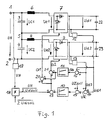
- a first DC chopper 7 (step-up converter or system of step-down and step-up converter) is connected with its first input terminal via an inductor 6 to the positive pole 1 and with its second input terminal directly to the center point 5.
- the intermediate circuit voltage at the output of the actuator 7 or at the capacitor 22 is denoted by Ud1.
- a second DC chopper 9 (step-up converter or system of step-down and step-up converter) is connected with its first input terminal via an inductor 8 to the center 5 and with its second input terminal directly to the negative pole 2.
- the intermediate circuit voltage at the output of the actuator 9 or at the capacitor 23 is also included Designated Ud2.
- a sum voltage regulator 10 and a differential voltage regulator 11 are provided to regulate the intermediate circuit voltages Ud1, Ud2.
- voltage detection devices 12 and 13 are provided for the detection of the intermediate circuit voltages Udl and Ud2.
- a summation point 14 adds both voltages Ud1, Ud2 and supplies the sum voltage U ⁇ to a comparison point 15.
- the comparison point 15 forms the deviation U ⁇ Soll - U ⁇ and feeds it to the sum voltage regulator 10.
- a voltage detection device 19 is provided to determine the mains voltage UN (direct voltage) present between the positive pole 1 and the negative pole 2.
- the mains voltage UN is multiplied by a multiplier 18 with the signal 1 / (2 Ud soll ) to the product UN / (2 Ud soll ).
- the difference between the product UN / (2 Ud soll ) about the output value of the sum voltage regulator 10 is formed in the sense of a feedforward control.
- the signal formed in this way is increased by the output value of the differential voltage regulator 11 in a summation point 20 and decreased by the output value of the total voltage regulator 11 in a comparison point 21.
- the control target value is the target of the different DC voltages to Ud1, Ud2 should maintain a predetermined value, for example, 2.8 KV.
- the two direct current actuators 7, 9 serve as actuators and the two duty cycles a1, a2 of the actuators are used as actuating variables.
- a control deviation of the sum voltage U ⁇ leads to a change of a1 + a2 and thus of Ue1 + Ue2. If the total voltage U ⁇ is too low, for example, reducing a1 + a2 and thus Ue1 + Ue2 leads to an increase in the current consumed by the network, thus to an increase in the transmitted power and thus ultimately to an increase in the total voltage U ⁇ .
- a control deviation of the differential voltage U ⁇ leads to a change in the difference between a1 and a2.
- DC controllers 72 and 92 are provided, each with two ignitable and erasable valves 72a, 72b and 92a, 92b.
- the anode of the valve 72a and the anode of the diode 72c are connected to the first input terminal of the DC chopper 72.
- the anode of valve 72b and the anode of diode 72d are connected to the second input terminal.
- the cathodes of both diodes 72c, 72d are connected together and form the first output terminal.
- the third input terminal of the DC chopper 72 is connected to the cathodes of both valves 72a, 72b and at the same time forms the second output terminal.
- the cathodes of both valves 92a, 92b are connected to the first input terminal of the DC chopper 92.
- the first input terminal also forms the first output terminal.
- the cathode of valve 92b and the cathode of diode 92d are located at the second input terminal.
- the cathode of valve 92a and the cathode of diode 92c are connected to the third input terminal.
- the anodes of both diodes 92c, 92d are connected together and form the second output terminal.
- the first and second input terminals of the actuator 72 are each connected to the positive pole via their own inductors 6a and 6b, and the second and third input terminals of the actuator 92 are each connected to the negative pole via their own inductors 8a and 8b.
- An inductor 24 and a current detection device 25 lie between the positive pole 1 and the common connection point of the capacitor 3 and the inductors 6a, 6b.
- the detected input current is designated Ie.
- Current detection devices 26 and 27 are provided between the inductance 6a and the first input terminal 72 and between the inductance 6b and the second input terminal of the actuator 72.
- the detected actuator currents are labeled Is1 and Is2.
- An inductor 28 lies between the negative pole 2 and the common connection point of the capacitor 4 and the inductors 8a, 8b. Between the inductor 8a and the second input terminal of the actuator 92 or the inductor 8b and the third input terminal of the actuator 9a current detection devices 29 and 30 are provided. The detected actuator currents are labeled Is3 and Is4.
- the further connection of the capacitor 3 connected to the connection point 5 is connected to the input terminal of the DC chopper 72, while the further connection of the capacitor 4 connected to the connection point 5 is connected to the first input terminal of the DC chopper 92.
- Pulse width modulators 31 and 32 are provided to control the ignitable and extinguishable valves (e.g. GTO thyristors) 72a, 72b and 92a, 92b of the direct current controllers 72 and 92, respectively.
- the pulse width modulator 31 is supplied with the duty cycles a11 (for valve 72a), a12 (for valve 72b) and the pulse width modulator 32 with the duty cycles a21 (for valve 92b), a22 (for valve 92a).
- the pulse width modulators 31, 32 are each connected to the control inputs of the corresponding valves.
- a first DC voltage intermediate circuit with an intermediate circuit capacitor 22 is connected to the output terminals of the DC regulator 72 and a second DC voltage intermediate circuit with an intermediate circuit capacitor 23 is connected to the output terminal of the first DC regulator 92.
- a self-commutated inverter 33 is connected to the first DC voltage intermediate circuit.
- a current detection device 34 connected between the actuator 72 and the inverter 33 is used to detect the intermediate circuit current Id1.
- the inverter 33 feeds a three-phase motor 35.
- To the second DC A self-commutated inverter 36 is connected to the voltage intermediate circuit.
- a current detection device 37 arranged between the actuator 92 and the inverter serves to detect the intermediate circuit current Id2.
- the inverter 36 feeds a three-phase motor 38.
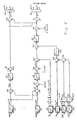
- FIG. 3 shows a control arrangement for the extended circuit arrangement according to FIG. 2.
- the summation point 41 is used for the damping (avoiding oscillation processes in the input filter 24, 28, 3, 4) to produce the output variable Damping controller addiet, with a value at the input of the damping controller that is proportional to the difference between the input current (vehicle input current) and the actuator input current.
- the output signal of the current regulator 42 is subtracted from the signal UN / (2 Ud soll ) in the comparison point 17 (pilot control).
- the output signal of the comparison point 17 is fed to a summation point 20 and a comparison point 21, as already under
- the output signal of the comparison point 21 - the pulse duty factor a2 - is fed to a summation point 43, from which the duty factor a21 can be found on the output side.
- the input current Ie is fed to a comparison point 44, which reduces the input current Ie by the actuator current Is and applies this difference signal to the summing point 41 via a damping controller 45.
- a comparison point 46 forms the difference signal Is3-Is4 and leads it via a balancing controller 47 to the summation point 43 and - with a negative sign - to a comparison point 48.
- the comparison point 48 receives the pulse duty factor a2 with a positive sign and outputs the pulse duty factor a22 on the output side.
- the sum voltage control circuit is subordinated to a current (limitation) control for the input current Ie absorbed by the network, which in turn contains a damping controller for vibrations in the input filter 24, 28, 3, 4 to prevent.
- the output signal of the summation point 49 is supplied via a limiter to the summation point 20 and - with a negative sign - to the comparison point 21 tet.
- the limiter 54 is used to limit the output signal of the differential voltage control circuit 11 or the output signal piloted by the signal A to the maximum permissible difference between the capacitor voltages Uc1 and Uc2.
- the output signal which can be obtained from the summation point 20 - the pulse duty factor a1 - is fed to a comparison point 50.
- the comparator 50 outputs the pulse duty factor a12 on the output side.
- a comparison point 51 forms the difference signal Is1-Is2 and passes this via a balancing controller 52 to a summation point 53 and - with a negative sign - to the comparison point 50.
- the summation point 53 receives the pulse duty factor a1 on the input side.
- the duty cycle can all be taken from the summation point 53.
- the mean value of the setpoint current setpoint Is soll (Id1 + Id2) Ud soll / UN and the signal UN / (2 Ud soll ) it is achieved that the controllers 10, 11 and 42 remain in the stationary case at the value zero.
- the 4 shows a circuit with two systems each consisting of buck and step-up converters.
- the anode of an ignitable and erasable valve 55 and the first terminal of the capacitor 3 are connected to the positive pole 1 via the inductance 24.
- the valve 55 lies above the inductance 6 of a current detection device 57 and a diode 59 on which it Most terminal of the intermediate circuit capacitor 22.
- the current detection device 57 is used to determine the actuator current Is1 'of the first system.
- a diode 56 with its cathode is connected to the common connection point of valve 55 and inductance 6, and an ignitable and erasable valve 58 with its anode is connected to the common connection point of diode 59 and current detection device 57.
- the further connections of diode 56 and valve 58 are connected to the interconnected second terminals of the capacitors 3 and 22.
- the intermediate circuit voltage Ud1 is in turn applied to the intermediate circuit capacitor 22.
- the negative pole 2 is connected to the first terminal of the capacitor 4 and to the cathode of an ignitable and erasable valve 60 via the inductor 28.
- the valve 60 is on the other hand above the inductor 8, a current detection device 62 and a diode 64 on the first terminal of the intermediate circuit capacitor 23.
- the current detection device 62 is used to determine the actuator current Is2 'of the second system.
- a diode 61 with its anode is connected to the common connection point of valve 60 and inductor 8, and an ignitable and erasable valve 63 with its cathode is connected to the common connection point of diode 64 and current detection device 62.
- the further connections of diode 61 and valve 63 are connected to the interconnected second terminals of the capacitors 4 and 23.
- the intermediate circuit voltage Ud2 is in turn applied to the intermediate circuit capacitor 23.
- the respective second terminals of the capacitors 3, 22, 4, 23 are connected to one another via the common connection point 5 (center point), so that there is an input-side series connection of the two systems.
- the duty cycles of the valves 55, 58, 60, 63 are designated a1T, a1H, a2T, a2H.
- the input current is again Ie.
- the intermediate circuit currents Id1, Id2 are in turn determined by means of current detection devices 34, 37.
- FIG. 5 shows a control arrangement for the circuit according to FIG. 4.
- the actual values Ud1, Ud2, Is, Ie, Is1 ′, Is2 ′ are smoothed using filters 65, 66, 67, 68, 69, 70.
- the further processing of the values Ud1 *, Ud2 * with the help of components 16, 11, 49, 20 and 14, 15, 10, 39, 40, 41, 42, 17, 21 and 44, 45 is carried out as described under FIG. 3 .
- the comparison point 44 is supplied with the output signals of two multipliers 77, 78 added in a summation point 79, the multiplier 77 forming the product 1 / 2Is1 * ⁇ a1T and the multiplier 78 forming the product 1 / 2ais2 * ⁇ a2T.
- the pulse duty factors of the step-up converter a1H, a2H and the step-down converter a1T, a2T are formed from the common manipulated variables a1, a2 in such a way that, with small mains voltages UN and permanently switched on, i.e. non-clocking step-down converter, the duty cycle of the step-up converter is identical to the common manipulated variable a1, a2 is that for larger mains voltages UN and permanently switched on, i.e.
- the duty cycle of the step-down converter is inversely proportional to the common manipulated variable a1, a2 and that in the transition area between when step-up and step-down converters are clocked, the duty cycle of the step-down converter a1T or a2T as a quotient a1H / a1 or a2H / a2 is formed between the duty cycle of the step-up converter and the common manipulated variable.
- the product a1H ⁇ a1T or a2H ⁇ a2T from the duty cycle a1H or a2H of the step-up converter and the duty cycle of the step-down converter a1T or a2T is equal to the common manipulated variable a1 or a2.
- the common manipulated variable a1 or a2 is then also proportional to the voltage transmission UC1 / Ud1 or UC2 / Ud2 of the respective entire actuator system for a step-up / boost converter system.
Abstract
Description
Die Erfindung bezieht sich auf ein Verfahren und eine Regelanordnung zur Regelung der Ausgangsspannungen von zwei Gleichstromstellern gemäß dem Oberbegriff des Anspruches 1.The invention relates to a method and a control arrangement for controlling the output voltages of two DC choppers according to the preamble of
In der DE-Patentanmeldung P 38 17 652.1 ist ein elektrisch betriebenes Schienentriebfahrzeug mit mindestens zwei Antriebsanlagen beschrieben, die jeweils mindestens einen Vierquadrantensteller, einen Gleichspannungszwischenkreis mit Zwischenkreiskondensator und einen selbstgeführten Wechselrichter zur Speisung mindestens eines Fahrmotors mit variabler Spannung und Frequenz aufweisen, wobei bei Wechselspannungs-Einspeisung jeder Vierquadrantensteller an einer eigenen Sekundärwicklung eines Transformators liegt und wobei die Vierquadrantensteller der Antriebsanlagen bei Einspeisung mit relativ hoher Gleichspannung über Schaltgeräte eingangsseitig in Reihe geschaltet sind.DE
Gemäß der DE-Patentanmeldung P 37 24 526.0 besteht eine Variante des Leistungsteils darin, anstelle der Vierquadrantensteller jeweils Systeme aus Tief- und Hochsetzstellern einzusetzen, die ebenfalls eingangsseitig und gegebenenfalls auch ausgangsseitig in Reihe geschaltet sind.According to DE
Der Erfindung liegt davon ausgehend die Aufgabe zugrunde, ein Verfahren zur Regelung der Ausgangsspannungen von zwei Gleichstromstellern der eingangs genannten Art anzugeben, das auch bei unterschiedlicher Belastung der beiden eingangsseitig in Reihe geschalteten Gleichstromsteller ein gutes und dynamisches Verhalten aufweist. Desweiteren soll eine Regelanordnung hierzu angegeben werden. Unter Gleichstromstellern können dabei auch Systeme aus Gleichstromstellern mit jeweils Hochsetz- oder Tief-Hochsetz-Verhalten verstanden werden.The invention is based on the object of specifying a method for regulating the output voltages of two DC choppers of the type mentioned at the outset, which has good and dynamic behavior even when the two DC choppers connected in series on the input side are subjected to different loads. Furthermore, a control arrangement for this is to be specified. DC controllers can also be understood to mean systems made of DC controllers, each with step-up or step-up-step behavior.
Diese Aufgabe wird bezuglich des Verfahrens in Verbindung mit den Merkmalen des Oberbegriffes erfindungsgemäß durch im Kennzeichen des Anspruches 1 angegebene Merkmale gelöst. Die Aufgabe wird bezüglich der Regelanordnung durch die im Anspruch 11 gekennzeichneten Merkmale gelöst.This object is achieved according to the invention in connection with the features of the preamble by features specified in the characterizing part of
Die mit der Erfindung erzielbaren Vorteile bestehen insbesondere darin, daß trotz der Verkopplung der beiden Gleichstromsteller infolge ihrer eingangsseitigen Reihenschaltung eine gute Dynamik der Regelung der Ausgangsspannungen beider Gleichstromsteller erzielt wird. Es wird vermieden, daß sich bei unterschiedlicher Belastung der beiden Gleichstromsteller unterschiedliche Ausgangsspannungen einstellen.The advantages which can be achieved with the invention consist in particular in that, despite the coupling of the two direct current regulators, a good dynamic of the regulation of the output voltages of both direct current regulators is achieved as a result of their series connection on the input side. It is avoided that different output voltages occur with different loads on the two direct current controllers.
Vorteilhafte Ausgestaltungen der Erfindung sind in den Unteransprüchen gekennzeichnet.Advantageous embodiments of the invention are characterized in the subclaims.
Die Erfindung wird nachstehend anhand der in der Zeichnung dargestellten Ausführungsbeispiele erläutert.The invention is explained below with reference to the embodiments shown in the drawing.
Es zeigen:
- Fig. 1 eine Schaltung mit zwei eingangsseitig in Reihe liegenden Gleichstromstellern inklusive Regelstruktur,
- Fig. 2 eine erweiterte Schaltungsanordnung,
- Fig. 3 eine Regelanordnung zur erweiterten Schaltungsanordnung,
- Fig. 4 eine Schaltung mit zwei jeweils aus Tiefsetz- und Hochsetzsteller bestehenden Systemen,
- Fig. 5 eine Regelanordnung zur Schaltung nach Fig. 4.
- 1 shows a circuit with two DC choppers including a control structure lying in series on the input side,
- 2 shows an expanded circuit arrangement,
- 3 shows a control arrangement for the extended circuit arrangement,
- 4 shows a circuit with two systems each consisting of step-down and step-up converters,
- 5 shows a control arrangement for the circuit according to FIG. 4.
In Fig. 1 ist eine Schaltung mit zwei eingangsseitig in Reihe liegenden Gleichstromstellern inklusive Regelstruktur dargestellt. Zwischen dem Pluspol 1 und dem Minuspol 2 eines Gleichspannungsnetzes (Netzspannung = UN) sind zwei Kondensatoren 3, 4 in Reihe geschaltet. Der gemeinsame Verbindungspunkt beider Kondensatoren 3, 4 ist mit Ziffer 5 (= Mittelpunkt) bezeichnet. Die an den Kondensatoren 3 bzw. 4 anstehenden Kondensatorspannungen betragen UC1 bzw. UC2. Ein erster Gleichstromsteller 7 (Hochsetzsteller oder System aus Tief- und Hochsetzsteller) ist mit seiner ersten Eingangsklemme über eine Induktivität 6 mit dem Pluspol 1 sowie mit seiner zweiten Eingangsklemme direkt mit dem Mittelpunkt 5 verbunden. (Beim System Tief-Hochsetzsteller ist keine Induktivität 6 zwischen Pluspol 1 und Stellereingang vorhanden.) Der Gleichstromsteller 1 (Eingangsspannung = Ue1) dient zur Speisung eines ersten Gleichspannungszwischenkreises mit Zwischenkreiskondensator 22. Die Zwischenkreisspannung am Ausgang des Stellers 7 bzw. am Kondensator 22 ist mit Ud1 bezeichnet. Ein zweiter Gleichstromsteller 9 (Hochsetzsteller oder System aus Tief- und Hochsetzsteller) ist mit seiner ersten Eingangsklemme über eine Induktivität 8 mit dem Mittelpunkt 5 sowie mit seiner zweiten Eingangsklemme direkt mit dem Minuspol 2 verbunden. (Beim System Tief-Hochsetzsteller ist keine Induktivität 8 zwischen Mittelpunkt 5 und Stellereingang vorhanden.) Der Gleichstromsteller 9 (Eingangsspannung = Ue2) dient zur Speisung eines zweiten Gleichspannungszwischenkreises mit Zwischenkreiskondensator 23. Die Zwischenkreisspannung am Ausgang des Stellers 9 bzw. am Kondensator 23 ist mit Ud2 bezeichnet.1 shows a circuit with two DC choppers, including a control structure, lying in series on the input side. Two
Zur Regelung der Zwischenkreisspannungen Ud1, Ud2 sind ein Summenspannungs-Regler 10 und ein Differenzspannungs-Regler 11 vorgesehen. Zur Bildung der Summenspannung UΣ = Ud2 + Ud1 und der Differenzspannung -UΔ = Ud2 - Ud1 sind Spannungserfassungseinrichtungen 12 bzw. 13 für die Erfassung der Zwischenkreisspannungen Udl bzw. Ud2 vorgesehen. Eine Summationsstelle 14 addiert beide Spannungen Ud1, Ud2 und führt die Summenspannung UΣ einer Vergleichsstelle 15 zu. Die Ver- gleichsstelle 15 bildet die Abweichung UΣSoll - UΣ und führt diese dem Summenspannungs-Regler 10 zu. Der Sollwert der Summenspannung UΣSoll entspricht dabei dem doppelten Zwischenkreisspannungs-Sollwert Udsoll, d.h. UΣsoll = 2Udsoll. Eine Vergleichsstelle 16 bildet die Differenz -UΔ = Ud2 - Ud1 und führt die Differenzspannung -UΔ dem Differenzspannungs-Regler 11 zu.A
Dabei wurde vereinfachend vorausgesetzt, daß der Wert des Sollwertes der Differenzspannung UΔsoll Null beträgt, so daß die entsprechende Vergleichsstelle für den UΔsoll/UΔ-Vergleich nicht dargestellt ist:
(UΔsoll -UΔ) = (0 - UΔ) = -UΔ.To simplify matters , it was assumed that the value of the setpoint of the differential voltage UΔ soll is zero, so that the corresponding comparison point for the UΔ soll / UΔ comparison is not shown:
(UΔ should -UΔ) = (0 - UΔ) = -UΔ.
Zur Ermittlung der zwischen Pluspol 1 und Minuspol 2 anliegenden Netzspannung UN (Gleichspannung) ist eine Spannungserfassungeinrichtung 19 vorgesehen. Die Netzspannung UN wird mittels eines Multiplizierers 18 mit dem Signal 1/(2 Udsoll) zum Produkt UN/(2 Udsoll) multipliziert. In einer Vergleichsstelle 17 Wird im Sinne einer Vorsteuerung die Differenz zwischen dem Produkt UN/(2 Udsoll) um den Ausgangswert des Summenspannungs-Reglers 10 gebildet. Das derart gebildete Signal Wird in einer Summationsstelle 20 um den Ausgangswert des Differenzspannungs-Reglers 11 erhöht und in einer Vergleichsstelle 21 um den Ausgangswert des Summenspannungs-Reglers 11 vermindert. Das der Summationsstelle 20 entnehmbare Tastverhältnis a1 = Ue1/Ud1 dient als Stellgröße zur Ansteuerung des Gleichstromstellers 7 und das der Vergleichsstelle 21 entnehmbare Tastverhältnis a2 = Ue2/Ud2 dient als Stellgröße zur Ansteuerung des Gleichstromstellers 9.A
Gemäß dem Regelziel soll der Sollwert der einzelnen Zwischenkreisspannungen Ud1soll, Ud2soll einen vorgegebenen Wert, z.B. 2,8 KV, einhalten. Als Stellglieder dienen die beiden Gleichstromsteller 7, 9 und als Stellgrößen werden die beiden Tastverhältnisse a1, a2 der Steller herangezogen. Durch die Verwendung der Summenspannung UΣ und Differenzspannung UΔ der beiden Zwischenkreisspannungen Ud1, Ud2 wird der Verkopplung der beiden Systeme 3, 6, 7, 22 und 4, 8, 9, 23 infolge ihrer ein gangsseitigen Reihenschaltung Rechnung getragen. Der Summenspannungs-Regler 10 bewirkt, daß die Summenspannung UΣ ihrem Sollwert UΣsoll = 2 Udsoll nachgeführt wird. Die Summenspannungs-Regelung beeinflußt dabei die Summe der Stellereingangsspannungen (= Summe der Tastverhältnisse a1 + a2). Eine Regelabweichung der Summenspannung UΣ führt zu einer Änderung von a1 + a2 und damit von Ue1 +Ue2. Ist die Summenspannung UΣ z.B. zu klein, so führt dies durch Verkleinerung von a1 + a2 und damit von Ue1 + Ue2 zu einem Anstieg des vom Netz aufgenommenen Stromes, damit zu einem Anstieg der übertragenen Leistung und somit schließlich zum Anstieg der Summenspannung UΣ.According to the control target value is the target of the different DC voltages to Ud1, Ud2 should maintain a predetermined value, for example, 2.8 KV. The two direct
Der Differenzspannungs-Regler bewirkt, daß die Differenzspannung UΔ = Ud1 - Ud2 zu Null wird. Eine Regelabweichung der Differenzspannung UΔ führt zu einer Änderung der Differenz zwischen a1 und a2. Ist die Zwischenkreisspannung Ud1 z.B. kleiner als die Zwischenkreisspannung Ud2, so führt dies zu einer Vergrößerung des Tastverhältnisses a1 bei gleichzeitiger Verkleinerung des Tastverhältnisses a2.The differential voltage regulator causes the differential voltage UΔ = Ud1 - Ud2 to become zero. A control deviation of the differential voltage UΔ leads to a change in the difference between a1 and a2. Is the intermediate circuit voltage Ud1 e.g. less than the intermediate circuit voltage Ud2, this leads to an increase in the duty cycle a1 with a simultaneous decrease in the duty cycle a2.
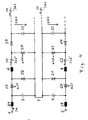
In Fig. 2 ist eine erweiterte Schaltungsanordnung dargestellt. Dabei sind Gleichstromsteller 72 bzw. 92 mit jeweils zwei zünd- und löschbaren Ventilen 72a, 72b bzw. 92a, 92b vorgesehen.An expanded circuit arrangement is shown in FIG.
Mit der ersten Eingangsklemme des Gleichstromstellers 72 sind die Anode des Ventils 72a und die Anode der Diode 72c verbunden. An der zweiten Eingangsklemme liegen die Anode des Ventils 72b und die Anode der Diode 72d. Die Kathoden beider Dioden 72c, 72d sind zusammengeschaltet und bilden die erste Ausgangsklemme. Die dritte Eingangsklemme des Gleichstromstellers 72 ist mit den Kathoden beider Ventile 72a, 72b verbunden und bildet gleichzeitig die zweite Ausgangsklemme.The anode of the
Mit der ersten Eingangsklemme des Gleichstromstellers 92 sind die Kathoden beider Ventile 92a, 92b verbunden. Die erste Eingangsklemme bildet gleichzeitig die erste Ausgangsklemme. An der zweiten Eingangsklemme liegen die Kathode des Ventils 92b und die Kathode der Diode 92d. An die dritte Eingangsklemme sind die Kathode des Ventils 92a und die Kathode der Diode 92c angeschlossen. Die Anoden beider Dioden 92c, 92d sind zusammengeschaltet und bilden die zweite Ausgangsklemme.The cathodes of both valves 92a, 92b are connected to the first input terminal of the
Die erste bzw. zweite Eingangsklemme des Stellers 72 sind jeweils über eigene Induktivitäten 6a bzw. 6b mit dem positiven Pol und die zweite bzw. dritte Eingangsklemme des Stellers 92 sind jeweils über eigene Induktivitäten 8a bzw. 8b mit dem negativen Pol verbunden. Zwischen dem Pluspol 1 und dem gemeinsamen Verbindungspunkt des Kondensators 3 und der Induktivitäten 6a, 6b liegen eine Induktivität 24 und eine Stromerfassungseinrichtung 25. Der erfaßte Eingangsstrom ist mit Ie bezeichnet. Zwischen der Induktivität 6a und der ersten Eingangsklemme 72 bzw. zwischen der Induktivität 6b und der zweiten Eingangsklemme des Stellers 72 sind Stromerfassungseinrichtungen 26 bzw. 27 vorgesehen. Die erfaßten Stellerströme sind mit Is1 bzw. Is2 bezeichnet. Zwischen dem Minuspol 2 und dem gemeinsamen Verbindungspunkt des Kondensators 4 und den Induktivitäten 8a, 8b liegt eine Induktivität 28. Zwischen der Induktivität 8a und der zweiten Eingangsklemme des Stellers 92 bzw. der Induktivität 8b und der dritten Eingangsklemme des Stellers 9a sind Stromerfassungseinrichtungen 29 bzw. 30 vorgesehen. Die erfaßten Stellerströme sind mit Is3 bzw. Is4 bezeichnet.The first and second input terminals of the
Der an den Verbindungspunkt 5 angeschlossene weitere Anschluß des Kondensators 3 ist mit der Eingangsklemme des Gleichstromstellers 72 verbunden, während der an den Verbindungspunkt 5 angeschlossene weitere Anschluß des Kondensators 4 an der ersten Eingangsklemme des Gleichstromstellers 92 liegt.The further connection of the
Zur Ansteuerung der zünd- und löschbaren Ventile (z.B. GTO-Thyristoren) 72a, 72b bzw. 92a, 92b der Gleichstromsteller 72 bzw. 92 sind Pulsweitenmodulatoren 31 bzw. 32 vorgesehen. Dem Pulsweitenmodulator 31 werden dabei die Tastverhältnisse a11 (für Ventil 72a), a12 (für Ventil 72b) und dem Pulsweitenmodulator 32 die Tastverhältnisse a21 (für Ventil 92b), a22 (für Ventil 92a) zugeleitet. Ausgangsseitig sind die Pulsweitenmodulatoren 31, 32 jeweils mit den Steuereingängen der entsprechenden Ventile verbunden.
An die Ausgangsklemmen des Gleichstromstellers 72 ist ein erster Gleichspannungszwischenkreis mit Zwischenkreiskondensator 22 sowie an die Ausgangsklemme des ersten Gleichstromstellers 92 ein zweiter Gleichspannungszwischenkreis mit Zwischenkreiskondensator 23 angeschlossen. An den ersten Gleichspannungszwischenkreis ist ein selbstgeführter Wechselrichter 33 angeschlossen. Zur Erfassung des Zwischenkreisstromes Id1 dient eine zwischen Steller 72 und Wechselrichter 33 geschaltete Stromerfassungseinrichtung 34. Der Wechselrichter 33 speist einen Drehstrommotor 35. An den zweiten Gleich spannungszwischenkreis ist ein selbstgeführter Wechselrichter 36 angeschlossen. Zur Erfassung des Zwischenkreisstromes Id2 dient eine zwischen Steller 92 und Wechselrichter angeordnete Stromerfassungseinrichtung 37. Der Wechselrichter 36 speist einen Drehstrommotor 38.A first DC voltage intermediate circuit with an
In Fig. 3 ist eine Regelanordnung zur erweiterten Schaltungsanordnung gemäß Fig. 2 dargestellt. Wie bereits unter Fig. 1 erwähnt, wird mit Hilfe der Summationsstelle 14 die Summenspannung UΣ = Ud1 + Ud2 gebildet. In der Vergleichsstelle 15 wird die Differenz zwischen dem Sollwert der Summenspannung UΣsoll = 2 Udsoll und der Summenspannung UΣ gebildet und dem Summenspannungs-Regler 10 zugeführt. Das Ausgangssignal des Summenspannungs-Reglers 10 wird in einer Summationsstelle 39 mit dem Mittelwert des Stellerstrom-Sollwertes
Is = (Is1 + Is2 + Is3 + Is4)/2 vermindert und gelangt über eine Summationsstelle 41 zum Stromregler 42. Mittels der Summationsstelle 41 wird zum Zwecke der Dämpfung (Vermeidung von Schwingungsvorgängen im Eingangsfilter 24, 28, 3, 4) die Ausgangsgröße eines Dämpfungsreglers addiet, wobei am Eingang des Dämpfungsreglers eine Größe liegt, die proportional zur Differenz aus Eingangsstrom (Fahrzeugeingangsstrom) und Stellereingangsstrom ist. Das Ausgangssignal des Stromreglers 42 wird in der Vergleichsstelle 17 vom Signal UN/(2 Udsoll) abgezogen (Vorsteuerung). Das Ausgangssignal der Vergleichsstelle 17 wird einer Summationsstelle 20 und einer Vergleichsstelle 21 zugeleitet, wie bereits unterFIG. 3 shows a control arrangement for the extended circuit arrangement according to FIG. 2. As already mentioned under FIG. 1, the summation voltage UΣ = Ud1 + Ud2 is formed with the aid of the
Is = (Is1 + Is2 + Is3 + Is4) / 2 decreases and reaches the
Fig. 1 erwähnt. Das Ausgangssignal der Vergleichsstelle 21 - das Tastverhältnis a2 - wird einer Summationsstelle 43 zugeleitet, der ausgangsseitig das Tastverhaltnis a21 entnehmbar ist.Fig. 1 mentioned. The output signal of the comparison point 21 - the pulse duty factor a2 - is fed to a
Der Eingangsstrom Ie wird einer Vergleichsstelle 44 zugeleitet, die den Eingangsstrom Ie um den Stellerstrom Is vermindert und dieses Differenzsignal über einen Dämpfungsregler 45 auf die Summationsstelle 41 aufschaltet. Eine Vergleichsstelle 46 bildet das Differenzsignal Is3 - Is4 und führt dieses über einen Symmetrierregler 47 zur Summationsstelle 43 und - mit negativem Vorzeichen - zu einer Vergleichsstelle 48. Die Vergleichsstelle 48 empfängt mit positivem Vorzeichen das Tastverhältnis a2 und gibt ausgangsseitig das Tastverhältnis a22 ab.The input current Ie is fed to a
Durch die im Vergleich zur Anordnung gemäß Fig. 1 neuen Bauteile 39 bis 42 und 44, 45 wird dem Summenspannungs-Regelkreis eine Strom(begrenzungs)-Regelung für den vom Netz aufgenommenen Eingangsstrom Ie unterlagert, der seinerseits einen Dämpfungsregler enthält, um Schwingungen im Eingangsfilter 24, 28, 3, 4 zu verhindern.Due to the
Die Vergleichsstelle 16 bildet die Differenzspannung -UΔ = Ud2 - Ud1 und führt diese dem Differenzspannungs-Regler 11 zu, wie bereits unter Fig. 1 erwähnt. Das Ausgangssignal des Differenzspannungs-Reglers 11 wird in einer Summationsstelle 49 im Sinne einer Vorsteuerung mit einem Signal
A = ((Id1 - Id2)/(Id1 + Id2)) · (UN/(2 Udsoll)) summiert. Das Ausgangssignal der Summationsstelle 49 wird über einen Begrenzer der Summationsstelle 20 und - mit negativem Vorzeichen - der Vergleichsstelle 21 zugelei tet. Der Begrenzer 54 dient zur Begrenzung des Ausgangssignals des Differenzspannungs-Regelkreises 11 bzw. des mit dem Signal A vorgesteuerten Ausgangssignals auf die maximal zulässige Differenz zwischen den Kondensatorspannungen Uc1 und Uc2. Das der Summationsstelle 20 entnehmbare Ausgangssignal - das Tastverhältnis a1 - wird einer Vergleichsstelle 50 zugeführt. Die Vergleichsstelle 50 gibt ausgangsseitig das Tastverhältnis a12 ab. Eine Vergleichsstelle 51 bildet das Differenzsignal Is1 - Is2 und leitet dieses über einen Symmetrierregler 52 zu einer Summationsstelle 53 und - mit negativem Vorzeichen - zur Vergleichsstelle 50. Die Summationsstelle 53 empfangt eingangsseitig das Tastverhältnis a1. Der Summationsstelle 53 ist das Tastverhältnis all entnehmbar.The
A = ((Id1 - Id2) / (Id1 + Id2)) · (UN / (2 Ud should )) summed. The output signal of the
Durch die Vorsteuerungen mittels des Signals A, des Mittelwertes des Stellerstrom-Sollwertes
Bei ungleicher Antriebsleistung der beiden Systeme 72-33-35 und 92-36-38 stellen sich unterschiedliche Spannungen Ue1, Ue2 an den Stellereingängen ein.If the drive power of the two systems 72-33-35 and 92-36-38 is different, different voltages Ue1, Ue2 are set at the actuator inputs.
In Fig. 4 ist eine Schaltung mit zwei jeweils aus Tief- und Hochsetzstellern bestehenden Systemen dargestellt. Dabei sind die Anode eines zünd- und löschbaren Ventils 55 und die erste Klemme des Kondensators 3 über die Induktivität 24 mit dem Pluspol 1 verbunden. Das Ventil 55 liegt andererseits über der Induktivität 6 einer Stromerfassungseinrichtung 57 und einer Diode 59 an der er sten Klemme des Zwischenkreiskondensators 22. Die Stromerfassungseinrichtung 57 dient zur Ermittlung des Stellerstromes Is1′ des ersten Systems. An den gemeinsamen Verbindungspunkt von Ventil 55 und Induktivität 6 ist eine Diode 56 mit ihrer Kathode und an den gemeinsamen Verbindungspunkt von Diode 59 und Stromerfassungseinrichtung 57 ist ein zünd- und löschbares Ventil 58 mit seiner Anode angeschlossen. Die weiteren Anschlüsse von Diode 56 und Ventil 58 liegen an den miteinander verbundenen zweiten Klemmen der Kondensatoren 3 und 22. Am Zwischenkreiskondensator 22 liegt wiederum die Zwischenkreisspannung Ud1 an.4 shows a circuit with two systems each consisting of buck and step-up converters. The anode of an ignitable and
Der Minuspol 2 ist über die Induktivität 28 mit der ersten Klemme des Kondensators 4 und mit der Kathode eines zünd- und löschbaren Ventils 60 verbunden. Das Ventil 60 liegt andererseits über der Induktivität 8, einer Stromerfassungseinrichtung 62 und einer Diode 64 an der ersten Klemme des Zwischenkreiskondensators 23. Die Stromerfassungseinrichtung 62 dient zur Ermittlung des Stellerstromes Is2′ des zweiten Systems. An den gemeinsamen Verbindungspunkt von Ventil 60 und Induktivität 8 ist eine Diode 61 mit ihrer Anode und an den gemeinsamen Verbindungspunkt von Diode 64 und Stromerfassungseinrichtung 62 ist ein zünd- und löschbares Ventil 63 mit seiner Kathode angeschlossen. Die Weiteren Anschlüsse von Diode 61 und Ventil 63 liegen an den miteinander verbundenen zweiten Klemmen der Kondensatoren 4 und 23. Am Zwischenkreiskondensator 23 liegt wiederum die Zwischenkreisspannung Ud2 an. Die jeweils zweiten Klemmen der Kondensatoren 3, 22, 4, 23 sind über den gemeinsamen Verbindungspunkt 5 (Mittelpunkt) miteinander verbunden, so daß sich eine eingangsseitige Reihenschaltung der beiden Systeme ergibt.The
Die Tastverhältnisse der Ventile 55, 58, 60, 63 sind mit a1T, a1H, a2T, a2H bezeichnet. Der Eingangsstrom beträgt wiederum Ie. Die Zwischenkreisströme Id1, Id2 werden wiederum mittels Stromerfassungseinrichtungen 34, 37 ermittelt.The duty cycles of the
Allgemein wird zur Erläuterung der Funktionsweise der Schaltung gemäß Fig. 4 auf die DE-Patentanmeldung P 37 24 526.0 hingewiesen.In general, reference is made to DE
In Fig. 5 ist eine Regelanordnung zur Schaltung nach Fig. 4 dargestellt. Die Istwerte Ud1, Ud2, Is, Ie, Is1′, Is2′ werden über Filter 65, 66, 67, 68, 69, 70 geglättet. Die an den Ausgängen der Filter anstehenden Werte sind mit Ud1*, Ud2*, Is* = 1/₂ (Is1* + Is2*), Ie*, 1/₂Is1*, 1/₂Is2* bezeichnet. Die weitere Verarbeitung der Werte Ud1*, Ud2* mit Hilfe der Bauglieder 16, 11, 49, 20 und 14, 15, 10, 39, 40, 41, 42, 17, 21 sowie 44, 45 erfolgt wie unter Fig. 3 beschrieben. Als stationärer Stellerstrom-Sollwert (Mittelwert) wird der Summationsstelle 39 die Größe
Der Vergleichsstelle 44 werden die in einer Summationsstelle 79 addierten Ausgangssignale zweier Multiplizierer 77, 78 zugeleitet, wobei der Multiplizierer 77 das Produkt 1/₂Is1* · a1T und der Multiplizierer 78 das Produkt 1/₂ais2* · a2T bildet.The
Die Tastverhältnisse der Hochsetzsteller a1H, a2H und der Tiefsetzsteller a1T, a2T werden in der Weise aus den gemeinsamen Stellgrößen a1, a2 gebildet, daß bei kleinen Netzspannungen UN und permanent eingeschaltetem, also nichttaktendem Tiefsetzsteller das Tastverhältnis des Hochsetzstellers mit der gemeinsamen Stellgröße a1, a2 identisch ist, daß bei größeren Netzspannungen UN und permanent eingeschaltetem, also nichttaktendem Hochsetzsteller das Tastverhältnis des Tiefsetzstellers umgekehrt proportional zur gemeinsamen Stellgröße a1, a2 ist und daß im Übergangsbereich dazwischen, wenn Hoch- und Tiefsetzsteller takten, das Tastverhältnis des Tiefsetzstellers a1T bzw. a2T als Quotient a1H/a1 bzw. a2H/a2 zwischen dem Tastverhältnis der Hochsetzsteller und der gemeinsamen Stellgröße gebildet wird.The pulse duty factors of the step-up converter a1H, a2H and the step-down converter a1T, a2T are formed from the common manipulated variables a1, a2 in such a way that, with small mains voltages UN and permanently switched on, i.e. non-clocking step-down converter, the duty cycle of the step-up converter is identical to the common manipulated variable a1, a2 is that for larger mains voltages UN and permanently switched on, i.e. non-clocking step-up converter, the duty cycle of the step-down converter is inversely proportional to the common manipulated variable a1, a2 and that in the transition area between when step-up and step-down converters are clocked, the duty cycle of the step-down converter a1T or a2T as a quotient a1H / a1 or a2H / a2 is formed between the duty cycle of the step-up converter and the common manipulated variable.
Durch arithmetische Verknüpfung oder angenähert durch Kennlinien wird dadurch erreicht, daß das Produkt a1H · a1T bzw. a2H · a2T aus dem Tastverhältnis a1H bzw. a2H des Hochsetzstellers und dem Tastverhältnis des Tiefsetzstellers a1T bzw. a2T gleich der gemeinsamen Stellgröße a1 bzw. a2 ist. Die gemeinsame Stellgröße a1 bzw. a2 ist dann auch für ein Tief-Hochsetzsteller-System proportional der Spannungsübersetzung UC1/Ud1 bzw. UC2/Ud2 des jeweiligen gesamten Stellersystems.By arithmetic linkage or approximated by characteristic curves it is achieved that the product a1H · a1T or a2H · a2T from the duty cycle a1H or a2H of the step-up converter and the duty cycle of the step-down converter a1T or a2T is equal to the common manipulated variable a1 or a2. The common manipulated variable a1 or a2 is then also proportional to the voltage transmission UC1 / Ud1 or UC2 / Ud2 of the respective entire actuator system for a step-up / boost converter system.
Claims (12)
Priority Applications (1)
| Application Number | Priority Date | Filing Date | Title |
|---|---|---|---|
| AT89117201T ATE79703T1 (en) | 1988-09-24 | 1989-09-18 | PROCEDURE AND CONTROL ARRANGEMENT FOR REGULATION OF THE OUTPUT VOLTAGES OF TWO DC CHANGER. |
Applications Claiming Priority (2)
| Application Number | Priority Date | Filing Date | Title |
|---|---|---|---|
| DE3832545A DE3832545A1 (en) | 1988-09-24 | 1988-09-24 | METHOD AND CONTROL ARRANGEMENT FOR CONTROLLING THE OUTPUT VOLTAGES OF TWO DC CONTROLLERS |
| DE3832545 | 1988-09-24 |
Publications (3)
| Publication Number | Publication Date |
|---|---|
| EP0361254A2 true EP0361254A2 (en) | 1990-04-04 |
| EP0361254A3 EP0361254A3 (en) | 1990-10-31 |
| EP0361254B1 EP0361254B1 (en) | 1992-08-19 |
Family
ID=6363674
Family Applications (1)
| Application Number | Title | Priority Date | Filing Date |
|---|---|---|---|
| EP89117201A Expired - Lifetime EP0361254B1 (en) | 1988-09-24 | 1989-09-18 | Method and control arrangement for controlling the output voltages of two dc supply devices |
Country Status (4)
| Country | Link |
|---|---|
| EP (1) | EP0361254B1 (en) |
| AT (1) | ATE79703T1 (en) |
| DE (2) | DE3832545A1 (en) |
| ES (1) | ES2035488T3 (en) |
Cited By (1)
| Publication number | Priority date | Publication date | Assignee | Title |
|---|---|---|---|---|
| EP2367275A1 (en) * | 2010-03-18 | 2011-09-21 | ABB Research Ltd | Non-isolated DC - DC converter for solar power plant |
Families Citing this family (3)
| Publication number | Priority date | Publication date | Assignee | Title |
|---|---|---|---|---|
| DE10302789B3 (en) * | 2003-01-24 | 2004-08-05 | Infineon Technologies Ag | Control circuit for detonation element of airbag passenger restraint system in automobile using step-up/step-down voltage converter for obtaining operating voltage from battery voltage |
| DE102005047373A1 (en) * | 2005-09-28 | 2007-04-05 | Schekulin, Dirk, Dr. Ing. | Low-setting plate circuit consists of input and output connections with main branches between them as well as input-side condenser and output-side diode series connections |
| DE102012101516A1 (en) | 2012-02-24 | 2013-08-29 | Pilz Gmbh & Co. Kg | Safety switching device with power supply |
Citations (1)
| Publication number | Priority date | Publication date | Assignee | Title |
|---|---|---|---|---|
| EP0169461A1 (en) * | 1984-07-13 | 1986-01-29 | Siemens Aktiengesellschaft | Circuit arrangement for supplying electrical appliances with direct voltage |
-
1988
- 1988-09-24 DE DE3832545A patent/DE3832545A1/en not_active Withdrawn
-
1989
- 1989-09-18 ES ES198989117201T patent/ES2035488T3/en not_active Expired - Lifetime
- 1989-09-18 AT AT89117201T patent/ATE79703T1/en not_active IP Right Cessation
- 1989-09-18 DE DE8989117201T patent/DE58902078D1/en not_active Expired - Fee Related
- 1989-09-18 EP EP89117201A patent/EP0361254B1/en not_active Expired - Lifetime
Patent Citations (1)
| Publication number | Priority date | Publication date | Assignee | Title |
|---|---|---|---|---|
| EP0169461A1 (en) * | 1984-07-13 | 1986-01-29 | Siemens Aktiengesellschaft | Circuit arrangement for supplying electrical appliances with direct voltage |
Cited By (2)
| Publication number | Priority date | Publication date | Assignee | Title |
|---|---|---|---|---|
| EP2367275A1 (en) * | 2010-03-18 | 2011-09-21 | ABB Research Ltd | Non-isolated DC - DC converter for solar power plant |
| US8488351B2 (en) | 2010-03-18 | 2013-07-16 | Abb Research Ltd. | Non-isolated DC-DC converter for solar power plant |
Also Published As
| Publication number | Publication date |
|---|---|
| ATE79703T1 (en) | 1992-09-15 |
| ES2035488T3 (en) | 1993-04-16 |
| EP0361254B1 (en) | 1992-08-19 |
| DE3832545A1 (en) | 1990-03-29 |
| DE58902078D1 (en) | 1992-09-24 |
| EP0361254A3 (en) | 1990-10-31 |
Similar Documents
| Publication | Publication Date | Title |
|---|---|---|
| DE60212818T2 (en) | Control device and method for a DC / DC converter | |
| EP0356547B1 (en) | Process for controlling a three-level inverter | |
| EP3743305B1 (en) | Method for controlling a battery current of a traction battery | |
| DE102017222380A1 (en) | On-board charging system | |
| DE102008001944A1 (en) | Device for controlling a DC-AC converter with a B2 circuit | |
| DE3221995C2 (en) | ||
| EP0193775A1 (en) | Control process for the voltage of the intermediate circuit of a converter with an intermediate circuit, and device to carry out this process | |
| WO2018069076A1 (en) | Control device for a dc converter, dc converter, and method for controlling a dc converter | |
| EP2156545A1 (en) | Pwm rectifier having target voltage corrector by zero system voltage for reducing switching losses and preventing noise generation | |
| EP3683950A1 (en) | Method for the control of a modular multilevel converter with half- and fullbridge cells | |
| EP0361254B1 (en) | Method and control arrangement for controlling the output voltages of two dc supply devices | |
| EP4022757A1 (en) | Control device for a dc converter, dc converter, and method for controlling a dc converter | |
| EP3672053A1 (en) | Control method for a dual active bridge series resonant converter and dual active bridge series resonant converter operating on the basis of this method | |
| WO2019057771A1 (en) | Ac/dc converter having step-up/step-down converter phase modules | |
| EP3668745B1 (en) | Energy storage arrangement and method for operating such energy storage arrangement | |
| DE3041963C2 (en) | AC-fed power converter arrangement for vehicles | |
| EP1053588B1 (en) | Methods for establishing control commands for electronic power converters | |
| WO2019166642A1 (en) | Method for controlling a three-phase pulse rectifier system | |
| EP0586369B1 (en) | Method and circuit for direct-current transmission | |
| DE3130356C2 (en) | Control arrangement for the even load distribution of two power supply devices connected in parallel on the output side | |
| EP4200963A1 (en) | Method and apparatus for ascertaining an average choke current or an input or output voltage in a step-up or step-down converter | |
| DE102022203234A1 (en) | DC-DC converter device and method for operating a DC-DC converter device | |
| WO2019063489A1 (en) | Method for operating a dc-dc converter having a plurality of power circuit branches | |
| EP4200968A1 (en) | Method and apparatus for ascertaining a parameter, said parameter characterizing a current or a voltage in a circuit arrangement | |
| DE112022000443T5 (en) | DUAL ACTIVE BRIDGE OPTIMIZATION WITH TRIPLE PHASE SHIFT AND VARIABLE INDUCTIVITY |
Legal Events
| Date | Code | Title | Description |
|---|---|---|---|
| PUAI | Public reference made under article 153(3) epc to a published international application that has entered the european phase |
Free format text: ORIGINAL CODE: 0009012 |
|
| AK | Designated contracting states |
Kind code of ref document: A2 Designated state(s): AT BE CH DE ES FR GB IT LI NL |
|
| PUAL | Search report despatched |
Free format text: ORIGINAL CODE: 0009013 |
|
| AK | Designated contracting states |
Kind code of ref document: A3 Designated state(s): AT BE CH DE ES FR GB IT LI NL |
|
| 17P | Request for examination filed |
Effective date: 19901222 |
|
| 17Q | First examination report despatched |
Effective date: 19910927 |
|
| GRAA | (expected) grant |
Free format text: ORIGINAL CODE: 0009210 |
|
| AK | Designated contracting states |
Kind code of ref document: B1 Designated state(s): AT BE CH DE ES FR GB IT LI NL |
|
| REF | Corresponds to: |
Ref document number: 79703 Country of ref document: AT Date of ref document: 19920915 Kind code of ref document: T |
|
| PGFP | Annual fee paid to national office [announced via postgrant information from national office to epo] |
Ref country code: CH Payment date: 19920903 Year of fee payment: 4 |
|
| ET | Fr: translation filed | ||
| REF | Corresponds to: |
Ref document number: 58902078 Country of ref document: DE Date of ref document: 19920924 |
|
| PGFP | Annual fee paid to national office [announced via postgrant information from national office to epo] |
Ref country code: ES Payment date: 19920930 Year of fee payment: 4 |
|
| GBT | Gb: translation of ep patent filed (gb section 77(6)(a)/1977) | ||
| ITF | It: translation for a ep patent filed |
Owner name: DE DOMINICIS & MAYER S. |
|
| REG | Reference to a national code |
Ref country code: ES Ref legal event code: FG2A Ref document number: 2035488 Country of ref document: ES Kind code of ref document: T3 |
|
| PLBE | No opposition filed within time limit |
Free format text: ORIGINAL CODE: 0009261 |
|
| STAA | Information on the status of an ep patent application or granted ep patent |
Free format text: STATUS: NO OPPOSITION FILED WITHIN TIME LIMIT |
|
| 26N | No opposition filed | ||
| PG25 | Lapsed in a contracting state [announced via postgrant information from national office to epo] |
Ref country code: ES Free format text: LAPSE BECAUSE OF EXPIRATION OF PROTECTION Effective date: 19930920 |
|
| PG25 | Lapsed in a contracting state [announced via postgrant information from national office to epo] |
Ref country code: LI Effective date: 19930930 Ref country code: CH Effective date: 19930930 |
|
| REG | Reference to a national code |
Ref country code: CH Ref legal event code: PL |
|
| PGFP | Annual fee paid to national office [announced via postgrant information from national office to epo] |
Ref country code: NL Payment date: 19940930 Year of fee payment: 6 |
|
| PGFP | Annual fee paid to national office [announced via postgrant information from national office to epo] |
Ref country code: GB Payment date: 19950814 Year of fee payment: 7 |
|
| PGFP | Annual fee paid to national office [announced via postgrant information from national office to epo] |
Ref country code: FR Payment date: 19950821 Year of fee payment: 7 |
|
| PGFP | Annual fee paid to national office [announced via postgrant information from national office to epo] |
Ref country code: AT Payment date: 19950822 Year of fee payment: 7 |
|
| PG25 | Lapsed in a contracting state [announced via postgrant information from national office to epo] |
Ref country code: NL Effective date: 19960401 |
|
| NLV4 | Nl: lapsed or anulled due to non-payment of the annual fee |
Effective date: 19960401 |
|
| PG25 | Lapsed in a contracting state [announced via postgrant information from national office to epo] |
Ref country code: GB Effective date: 19960918 Ref country code: AT Effective date: 19960918 |
|
| PG25 | Lapsed in a contracting state [announced via postgrant information from national office to epo] |
Ref country code: FR Effective date: 19960930 |
|
| GBPC | Gb: european patent ceased through non-payment of renewal fee |
Effective date: 19960918 |
|
| REG | Reference to a national code |
Ref country code: FR Ref legal event code: ST |
|
| REG | Reference to a national code |
Ref country code: FR Ref legal event code: ST |
|
| PGFP | Annual fee paid to national office [announced via postgrant information from national office to epo] |
Ref country code: BE Payment date: 19980714 Year of fee payment: 10 |
|
| REG | Reference to a national code |
Ref country code: ES Ref legal event code: FD2A Effective date: 19990601 |
|
| PG25 | Lapsed in a contracting state [announced via postgrant information from national office to epo] |
Ref country code: BE Free format text: LAPSE BECAUSE OF NON-PAYMENT OF DUE FEES Effective date: 19990930 |
|
| BERE | Be: lapsed |
Owner name: ASEA BROWN BOVERI A.G. Effective date: 19990930 |
|
| PGFP | Annual fee paid to national office [announced via postgrant information from national office to epo] |
Ref country code: DE Payment date: 20030925 Year of fee payment: 15 |
|
| PG25 | Lapsed in a contracting state [announced via postgrant information from national office to epo] |
Ref country code: DE Free format text: LAPSE BECAUSE OF NON-PAYMENT OF DUE FEES Effective date: 20050401 |
|
| PG25 | Lapsed in a contracting state [announced via postgrant information from national office to epo] |
Ref country code: IT Free format text: LAPSE BECAUSE OF NON-PAYMENT OF DUE FEES;WARNING: LAPSES OF ITALIAN PATENTS WITH EFFECTIVE DATE BEFORE 2007 MAY HAVE OCCURRED AT ANY TIME BEFORE 2007. THE CORRECT EFFECTIVE DATE MAY BE DIFFERENT FROM THE ONE RECORDED. Effective date: 20050918 |