EP0241286B2 - An auto-tuning controller - Google Patents
An auto-tuning controller Download PDFInfo
- Publication number
- EP0241286B2 EP0241286B2 EP87303089A EP87303089A EP0241286B2 EP 0241286 B2 EP0241286 B2 EP 0241286B2 EP 87303089 A EP87303089 A EP 87303089A EP 87303089 A EP87303089 A EP 87303089A EP 0241286 B2 EP0241286 B2 EP 0241286B2
- Authority
- EP
- European Patent Office
- Prior art keywords
- signal
- variable
- error
- extractor
- controller
- Prior art date
- Legal status (The legal status is an assumption and is not a legal conclusion. Google has not performed a legal analysis and makes no representation as to the accuracy of the status listed.)
- Expired - Lifetime
Links
Images


Classifications
-
- G—PHYSICS
- G05—CONTROLLING; REGULATING
- G05B—CONTROL OR REGULATING SYSTEMS IN GENERAL; FUNCTIONAL ELEMENTS OF SUCH SYSTEMS; MONITORING OR TESTING ARRANGEMENTS FOR SUCH SYSTEMS OR ELEMENTS
- G05B13/00—Adaptive control systems, i.e. systems automatically adjusting themselves to have a performance which is optimum according to some preassigned criterion
- G05B13/02—Adaptive control systems, i.e. systems automatically adjusting themselves to have a performance which is optimum according to some preassigned criterion electric
- G05B13/0265—Adaptive control systems, i.e. systems automatically adjusting themselves to have a performance which is optimum according to some preassigned criterion electric the criterion being a learning criterion
- G05B13/0275—Adaptive control systems, i.e. systems automatically adjusting themselves to have a performance which is optimum according to some preassigned criterion electric the criterion being a learning criterion using fuzzy logic only
-
- G—PHYSICS
- G05—CONTROLLING; REGULATING
- G05B—CONTROL OR REGULATING SYSTEMS IN GENERAL; FUNCTIONAL ELEMENTS OF SUCH SYSTEMS; MONITORING OR TESTING ARRANGEMENTS FOR SUCH SYSTEMS OR ELEMENTS
- G05B13/00—Adaptive control systems, i.e. systems automatically adjusting themselves to have a performance which is optimum according to some preassigned criterion
- G05B13/02—Adaptive control systems, i.e. systems automatically adjusting themselves to have a performance which is optimum according to some preassigned criterion electric
- G05B13/0205—Adaptive control systems, i.e. systems automatically adjusting themselves to have a performance which is optimum according to some preassigned criterion electric not using a model or a simulator of the controlled system
- G05B13/024—Adaptive control systems, i.e. systems automatically adjusting themselves to have a performance which is optimum according to some preassigned criterion electric not using a model or a simulator of the controlled system in which a parameter or coefficient is automatically adjusted to optimise the performance
-
- Y—GENERAL TAGGING OF NEW TECHNOLOGICAL DEVELOPMENTS; GENERAL TAGGING OF CROSS-SECTIONAL TECHNOLOGIES SPANNING OVER SEVERAL SECTIONS OF THE IPC; TECHNICAL SUBJECTS COVERED BY FORMER USPC CROSS-REFERENCE ART COLLECTIONS [XRACs] AND DIGESTS
- Y10—TECHNICAL SUBJECTS COVERED BY FORMER USPC
- Y10S—TECHNICAL SUBJECTS COVERED BY FORMER USPC CROSS-REFERENCE ART COLLECTIONS [XRACs] AND DIGESTS
- Y10S706/00—Data processing: artificial intelligence
- Y10S706/90—Fuzzy logic
-
- Y—GENERAL TAGGING OF NEW TECHNOLOGICAL DEVELOPMENTS; GENERAL TAGGING OF CROSS-SECTIONAL TECHNOLOGIES SPANNING OVER SEVERAL SECTIONS OF THE IPC; TECHNICAL SUBJECTS COVERED BY FORMER USPC CROSS-REFERENCE ART COLLECTIONS [XRACs] AND DIGESTS
- Y10—TECHNICAL SUBJECTS COVERED BY FORMER USPC
- Y10S—TECHNICAL SUBJECTS COVERED BY FORMER USPC CROSS-REFERENCE ART COLLECTIONS [XRACs] AND DIGESTS
- Y10S706/00—Data processing: artificial intelligence
- Y10S706/902—Application using ai with detail of the ai system
- Y10S706/903—Control
- Y10S706/906—Process plant
Description
- The present invention relates to an auto-tuning control apparatus provided with a function of automatically adjusting one or more control parameters in accordance with the characteristics of a controlled system and which may be used, for example, for conducting process control.
- Conventionally, an auto-tuning controller such as shown in Figure 19 is adopted. This is one recited in an article by A.B. Corripio, P.M. Tompkins, "Industrial Application of a Self-Tuning Feedback Control Algorithm", ISA Transactions, vol. 20, No. 2,1981,
pp 3 to 10. In Figure 19, thereference numeral 1 designates a reference value signal generator, thereference numeral 502 designates an auto-tuning controller, thereference numeral 3 designates a controlled system, thereference numeral 4 designates a PID controller, thereference numeral 5 designates a mathematical model operator, thereference numeral 6 designates an identifier, and the Reference numeral 7 designates an adjustment operator. - The operation of this device will be described.
- The auto-
tuning controller 502 receives the reference value signal r(k) which is output from the referencevalue signal generator 1 and the controlled variable y(k) which is output from the controlledsystem 3 as its inputs, and outputs a manipulated variable u(k) which is to be input to the controlledsystem 3. The values in parenthesis represent discrete timings at respective sampling invervals. - The operation inside the auto-tuning controller is as described below.
- At first, an error e(k) between the reference value signal r(k) and the controlled variable y(k) is calculated.

- The
PID controller 4 receives the error e(k) as its input, and calculates the manipulated variable u(k) with the use of the control parameters which are previously established to output the same. The control parameters in thePID controller 4 are the gain Kc, integration time T, and differentiation time TD, and the manipulated variable u(k) is calculated from these parameters as in the following.
- The manipulated variable u(k) becomes the input to the controlled
system 3 as well as the inputs to themathematical model operator 5 and theidentifier 6. - The
mathematical model operator 5 calculates the output v(k) from the input manipulated variable u(k), for example, with the use of such as the mathematcial model of the following formula.
- Herein, m is an integer larger than or equal to 0, which means a dead time.
- The
identifier 6 obtains the coefficients a1, a2, b1, and b2 of the formula (3) such that the input-output relation of the controlledsystem 3 and that of themathematical model operator 5 are equivalent to each other, that is, the outputs y(k) and v(k) of the both circuits are equal to each other. For this purpose, theidentifier 6 receives the manipulated variable u(k), the controlled variable y(k), and the output of the mathematical model v(k) as its inputs. - For the description of the operation of the
identifier 6, the following vectors x(k), z(k), and ø(k) are defined.


- Herein, the suffix T at right shoulder of the vector represents a transpose of the vector.
- The
identifier 6 executes the next algorithm.


- The vector ø(k), that is, the coefficients a1, a2, b1, and b2 of the mathematical model formula (3) are obtained successively by this algorithm.
- The vector ø(k) which is obtained in this way is output from the
identifier 6, and is sent to themathematical model operator 5 to be used for modifying the mathematical model, and is sent to the adjustment operator 7 to be used for obtaining the control parameters, that is, the gain Kc, integration time T, and differentiation time TD. The adjustment operator 7 conducts the following operation in order to obtain these control parameters.


- Herein, Q which appears in the formulae (10) and (12) are defined by the following formula.

- Herein, 8 is an adjustment parameter, and in more detail, a desired time constant in a dosed loop.
- The gain Kc, integration time T , and differentiation time To obtained in this way are sent to the
PID controller 4 to be again used for calculating the manipulated variable u(k) from the error e(k) with using the formula (2). - In this prior art auto-tuning controller with such a construction it is required to conduct the identification of the controlled system, and there are following problems in this identification.
-
- (1) The calculation is very complicated.
- (2) The quantity of the calculation amounts to a large volume.
- (3) It takes a long time for the calculation to converge.
- (4) It is impossible to deal with the non-linearity which is possesed by the controlled system.
- (5) This controller is improperforthe identification of the controlled system of the type other than that which is determined by the mathematical model of the formula (3) because the type of the mathematical model is restricted to that of the formula (3) in this controller.
- (6) There arises redundancy because the four coefficients a1, a2, b1, and b2 are identified in order to obtain the three control parameters Kp, T, and Tp.
- Mention is made here of an article entitled "Fuzzy PID Supervisor" by H.R. van Nauta Lemke et al which appeared in the Proceedings of the 24th IEEE Conference on Decision & Control, 11th-13th December 1985, pages 602-608. An auto-tuning control apparatus is described in which fuzzy logic is applied to the control of a PID controller. This is based upon the extraction of an error signal which is formed in the apparatus as the difference between a process monitoring variable and a reference signal. This error signal is passed through a differentiator and both the differentiated output signal produced and the error signal are utilised by the Fuzzy PID Supervisor. These signals are scaled and sampled. Then follows fuzification, application of fuzzy rules, and defuzzification, in course of producing increments for adjusting the PID control parameters.
- The present invention is intended to provide an auto-tuning controller capable of generating optimum control parameters of the controlled system from characteristics variables which are extracted from the waveform of an errorsignal using fuzzy reasoning rules previously obtained from experience and human perception without any need to conduct model identification of the controlled system.
- This intention is realized by implementing the features of
claim 1. - The error signal upon which the characteristics variables extractor operates may be one derived within the controller external to the extractor. Altematively, the error signal may be derived within the extractor from other signals - e.g. from the output controlled variable and an applied reference signal, or alternatively from the output controlled variable and a test signal applied either directly or indirectly to the controlled system.
- The samples of the error signal waveform may be regular samples. Such may be used for deriving mean error and/or mean error change rate. Additionally or alternatively the samples may be feature dependant and obtained at irregular time intervals - e.g. they may be peak value samples.
- In the accompanying drawings:
- Figure 1 is a block diagram showing an auto-tuning controller as a first embodiment of the present invention;
- Figure 2 is a flowchart describing the operation of the first embodiment;
- Figure 3 is a diagram showing an example of evaluation by the membership function thereof;
- Figure 4 is a diagram showing the mechanism of the fuzzy reasoning thereof;
- Figure 5 is a block diagram showing an auto-tuning controller as a second embodiment of the present invention;
- Figure 6 is a flowchart describing the operation of the second embodiment;
- Figure 7 is a diagram showing an example of evaluation by the membership function thereof;
- Figure 8 is a diagram showing the mechanism of the fuzzy reasoning thereof;
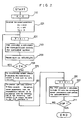
- Figure 9 is a block diagram showing an auto-tuning controller as a third embodiment of the present invention;
- Figure 10 is a flowchart describing the operation of the third embodiment;
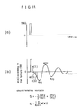
- Figure 11 is a diagram showing an example of evaluation by the membership function thereof;
- Figure 12 is a diagram showing the mechanism of the fuzzy reasoning thereof;
- Figure 13 is a block diagram showing a fourth embodiment of the present invention;
- Figure 14 is a flowchart describing the operation of the fourth embodiment;
- Figure 15 is a diagram showing the mechanism of the fuzzy reasoning thereof;
- Figure 16 is a blocs diagram showing an auto-tuning controller as a fifth embodiment of the present invention;
- Figure 17 is a flowchart describing the operation of the fifth embodiment;
- Figure 18 is a diagram showing the mechanism of the fuzzy reasoning thereof; and
- Figure 19 is a block diagram showing a prior art auto-tuning controller.
- In order that this invention might be better understood, embodiments thereof will now be particularised and reference will be made to the drawings aforesaid. The description that follows is given by way of example only.
- Figure 1 shows an auto-tuning controller as a first embodiment of the present invention. In Figure 1, the
reference numeral 1 designates a reference value signal generator, which generates a reference value signal r(k). Thereference numeral 2 designates an auto-tuning controller, and this auto-tuning controller receives the reference value signal r(K) and the controlled variable y(k) which is the output of the controlledsystem 3, and outputs the manipulated variable u(k). Thereference numeral 3 designates a controlled system. This controlledsystem 3 receives the manipulated variable u(k) and outputs the controlled variable y(k). As described above, the controlled variable y(k) is fed back to the auto-tuning controller 2. - The internal construction of the auto-
tuning controller 2 will be described. - The
reference numeral 4 designates a controller, and in this embodiment a PID controller is used therefor. This PID controller4 receives the error between the reference value signal r(k) and the controlled variable y(k), and outputs the manipulated variable u(k) in accordance with the previously established control parameters, that is, the gain Kc, integration time T, and differentiation time TD. Thereference numeral 8 designates a characteristics variables extractor which receives such as the error e(k), and/or the reference value signal r(k) and the manipulated variable y(k), and outputs the characteristics variable Si; i = 1,2,..., n representing the characteristics of the controlledsystem 3. Thereference numeral 9 designates a reasoning rule memory which stores the reasoning rules Rj ; j = 1, 2, ..., m to be used for deriving the optimum control parameters from the characteristics variables S. Thereference numeral 10 designates a position type fuzzy reasoner which reasons and outputs the optimum control parameters, that is, the gain Kc, integration time T, and differentiation time TD in accordance with the reasoning rule Rj upon receiving the input characteristics variable S. The Kc, T, and TD are given to thePID controller 4 to be used again for the calculation of the manipulated variable u(k). Thus, anadjustment section 11 for adjusting the control parameters of thecontroller 4 by a fuzzy reasoning in accordance with the reasoning rule is constituted by the characteristicsvariable extractor 8 and the position typefuzzy reasoner 10. - The operation of this device will be described with reference to the flowchart of Figure 2.
- At first, the value of K is set to 0 at
step 111, Next, the control parameters are initiallized atstep 121 as in the following. That is, the gain Kc is initiallized at a relatively small value Kco. The integration time T and differentiation time TD are initiallized at infinity and 0, respectively, or at maximum and minimum, respectively. ThePID controller 4 calculates the formula (2) with the use of the above-described initiallized parameters and controls the controlledsystem 3. Meanwhile, such as the error e(k), the reference value signal r(k), or the controlled variable y(k) are recorded. - When these data are gathered over n samples, the characteristics
variable extractor 8 calculates the characteristics variable Si; i = 1, 2, ..., n from these data. The above-described characteristics variables are as described below.

- At
step 181 the position typefuzzy reasoner 10 fuzzy reasons the optimum control parameters from the characteristics variable in accordance with the reasoning rules Rj ; j = 1, 2, ..., m stored at thereasoning rule memory 9, and outputs the same to thePID controller 4. - Thereafter, at
steps 191 to 201 thePID controller 4 calculates the formula (2) with the use of the control parameters given described above and continues the control of the controlledsystem 3. - The reasoning rule Rj stored at the
reasoning rule memory 9 and the operation of the position typefuzzy reasoner 10 will be described. - At first, the reasoning rules Rj are those produced by that the experience rules or perceptions which a person utilizes in conducting the adjustment of control parameters are made rules, and these are, for example, as in the following.
- R1: "If the mean error S1 is large and the mean error change rate S2 is large, then set the gain Kc at an intermediate value."
- R2: "If the mean error S1 is large and the mean error change rate S2 is small, then set the gain Kc at a large value."
- As described above, the reasoning rule Rj has a form of "If~, then ~.". The portion "If ~," is called a former part proposition, and the portion "then -." is called a latter part proposition.
- When the latter part proposition has a form of representing a value itself such as "take - as -" or "set - to ~" as in the above-described reasoning rules R1 and R2, this fuzzy reasoning is especially called a position type fuzzy reasoning. To the contrary, when the latter part proposition has a form of representing a variation of a value such as "increase - by ~" or "lengthen - by ~", this fuzzy reasoning is caller a velocity type fuzzy reasoning.
- In this first embodiment of the present invention, the position type
fuzzy reasoner 10 which conducts the position type fuzzy reasoning is provided. The operation of this position typefuzzy reasoner 10 will be described as follows. - In the fuzzy reasoning, at first it is evaluated how much degree the present state satisfies with the condition of the former part proposition with the use of the membership function, and it is represented by a value between 0 and 1.
- Figure 3 shows an example of evaluation by the membership function. Herein, a proposition "the mean error S1 is large" is adopted. It is assumed that the mean error calculated by the characteristics
variable extractor 8 is that S1 = S1*. Then, the degree to that the former part proposition comes into existence is evaluated as 0.75. - Figure 4 shows the mechanism of the fuzzy reasoning which is conducted by the position type
fuzzy reasoner 10. In this fuzzy reasoning, the mean error S1 and the mean error change rate S2 are selected as the characteristics variables, and the above-described rules R1 and R2 are used as reasoning rules. Herein, only the adjustment of the gain is described, but the principle of the reasoning is also applied to the adjustments of the integration time and the differentiation time. - At first, the degrees to that the former part propositions of the fuzzy reasoning rules R1 and R2 come into existence are evaluated as described above. Herein, when the former part proposition comprises a plurality of terms and has a form of "If ~ and ~", the lowest one among the degrees to that the respective terms come into existence becomes the degree to that the entirety of the former part proposition come into existence. In the example of Figure 4, the actual values of the mean error S1 and the mean error change rate S2 are that S1 = S1* and S2 = S2 *. Then, the degree to that the proposition "If the mean error S1 is large" of the rule R1 comes into existence is 0.75, and the degree to that the proposition "If the mean error change rate S2 is large" comes into existence is 0.2. Accordingly, the degree to that the entirety of the former part proposition comes into existence is 0.2.
- The latter part proposition is also represented by the membership function as shown in Figure 4. Because the degree to that the former part proposition of the rule R1 is 0.2, the membership function of the latter part proposition is reduced to 0.2 times as that of the latter part proposition itself.
- Finally, the reduced membership functions of the latter part propositions of the respective rules R1 and R2 are put one upon another, and the center of gravity of them is obtained. The value of the gain Kc at this center of gravity is adopted as the optimum gain.
- Similarly as above, the optimum integration time and the optimum differentiation time are reasoned.
- Figure 5 shows a second embodiment of the present invention.
- In Figure 5 the same reference numerals designate the same elements as those shown in Figure 1. The
reference numeral 108 designates a controlled system input switch for selecting one from the manipulated variable u(k) and the test signal T(k) as the input to be input to the controlledsystem 3. Thereference numeral 109 designates a test signal generator for generating a test signal T(k). The characteristicsvariable extractor 8 receives the test signal T(k) and the output y(k) of the controlledsystem 3 which is a response against the test signal T(k), and outputs a characteristics variable S ; i = 1, 2, ..., n representing the characteristics of the controlledsystem 3. Thereference numeral 102 designates an auto-tuning controller of this second embodiment, and theadjustment section 11 for adjusting the control parameters is constituted by the characteristicsvariable extractor 8, the position typefuzzy reasoner 10, and thetest signal generator 109. - The operation of this second embodiment will be described with reference to the flowchart of Figure 6.
- The operation of this embodiment is separated into a former part comprising the
steps 132 to 162 of the automatic adjustment mode for conducting the automatic adjustment of the control parameters and a latter part comprising thesteps 172 to 182 of the control mode for conducting the control of the controlledsystem 3 in accordance with the control parameters adjusted at the former part steps. - At first, the controlled
system input switch 108 is switched to the side a atstep 132. - Next, the
test signal generator 109 generates a test signal T(k) which is a step signal in this case atstep 142. The test signal T(k) becomes an input to the controlledsystem 3 through the controlledsystem input switch 108. - At
step 152 the characteristicsvariable extractor 8 receives the test signal T(k) and the output y(k) of the controlledsystem 3 which is a response against the test signal, and calculates the characteristics variable S, representing the control property of the controlledsystem 3 and outputs the same. - At
step 162, the position typefuzzy reasoner 10 fuzy-reasons the optimum control parameters from the characteristics variable S, in accordance with the reasoning rule Rj stored at thereasoning rule memory 9, and gives the same to thePID controller 4. - Thus, the former part operation, that is, the automatic adjustment of the control parameters is concluded.
- The latter part operation comprises the
steps system 3 after the adjustment of the control parameters. - At
step 172, the controlledsystem input switch 108 is switched to the side b. Thus, the input to the controlledsystem 3 is switched from the test signal T(k) to the manipulated variable u(k) which is the output of thePID controller 4. - At
step 182 thePID controller 4 calculates the formula (2) with the use of given control parameters and controls the controlledsystem 3. - Figure 7 shows an example of fuzzy reasoning by which the characteristics variable S, is extracted from the test signal T(k) and the output y(k) of the controlled
system 3 which is a response against the test signal T(k). Herein, a step signal is used as the test signal T(k). As the characteristics variable Si the followings S1 and S2 are, for example, selected with the use of the response error s(k) of the controlledsystem 3 against the test signal T(k) which is also shown below.


- Herein, N is a positive integer which is previously established, and Speak is the maximum peak of the s(k) at the negative side.
- In this second embodiment of the present invention, the position type
fuzzy reasoner 8 which conducts the position type fuzzy reasoning is provided. The operation thereof will be described as follows. - Figure 8 shows the mechanism of the position type fuzzy reasoning. Herein, the S1 and S2 of the formulae (17) and (18) are selected as characteristics variables, and R1 and R2 which are described below are used as reasoning rules.
- Ri : "If S1 is large and S2 is also large, then set the Kc at an intermediate value."
- R2: "If S1 is large and S2 is not large, then set the Kc at a large value."
- At first it is evaluated to how much degree the present state satisfies with the condition of the former part proposition of the fuzzy reasoning rules R1 and R2. Herein, the actual values of S1 and S2 are assumed to be that Si = Si * and S2 = S2 *. These values are evaluated by the membership functions. For example, with respect to the reasoning rule R1, if S1 is large and S2 is also large as shown by the left side two graphs at the upper stage of Figure 8 it is evaluated that the present state satisfies them to the degree of 0.75 and 0.2, respectively. Then, it is judged that the former part proposition of the rule R1 is satisfied to the degree of 0,2 from the lower value among them.
- The latter part proposition "set the Kc at an intermediate value" is also represented by a membership function, and this membership function is weighted by the degree to that the former part proposition comes into existence.
- Finally, the weighted membership functions of the latter part propositions of the respective rules R1 and R2 are put one upon another and the center of gravity of them is obtained. The value of the gain Kc of this center of gravity is adopted as the optimum gain.
- Similar operations as those described above are conducted also for the integration time and differentiation time.
- In this way, the position type
fuzzy reasoner 10 reasons the optimum control parameters. - Figure 9 shows a third embodiment of the present invention. In Figure 9 the same reference numerals designates the same elements as those shown in Figures 1 and 5. In this embodiment, an
error switch 208 is provided at a stage prior to thePID controller 4 so as to select one as error input e(k) which is to be input to thePID controller 4 from the error between the reference value signal r(k) and the output y(k) of the controlledsystem 3 and the error between the test signal T(k) from thetest signal generator 209 and the output y(k). Furthermore, the auto-tuning controller 202 of this third embodiment receives the reference value signal r(k) and the controlled variable y(k) which is the output of the controlledsystem 3 as its inputs, and outputs manipulated variable u(k). The output y(k) of the controlledsystem 3 is feedbacked to the auto-tuning controller 202. In this embodiment theadjustment section 11 for adjusting the control parameters are constituted by the characteristicsvariable extractor 8, the position typefuzzy reasoner 10, and thetest signal generator 209. - The operation of this third embodiment will be described with reference to the flowchart of Figure 10.
- In this flowchart, the former part steps 133 to 183 constitute an automatic adjustment mode for conducting the automatic adjustment of the control parameters, and the latter part steps 193 and 203 constitute a control mode for conducting the control of the controlled system in accordance with the control parameters adjusted at the former part steps.
- At first, at
step 133 the control parameters are initiallized at appropriate values. For example, the gain Kc is set at a relatively small value Kco, the integration time T1 and differentiation time To are set at infinity and 0, or at maximum and minimum, respectively. - At
steps 143 to 163 the PID controller4 receives the error e(k) between the test signal T(k) which is a pulse sianal in this case and the controlled variable v(k).
PID controller 4 controls the controlledsystem 3 in accordance with the test signal T(k) with the use of the initiallized control parameters. - At
step 173 the characteristicsvariable extractor 8 receives the error e(k) of the formula (17), and T(k), y(k) as its inputs, and calculates the characteristics variable S, representing the control property of the controlledsystem 3 to output the same. - At
step 183, the position typefuzzy reasoner 10 reasons the optimum control parameters from the characteristics variable S, in accordance with the reasoning rule Rj stored at thereasoning rule memory 9, and gives the same to thePID controller 4. - Having done the above-described steps, the operation of the automatic adjustment of control parameters, that is, the adjustment mode is concluded.
- At
step 193 the auto-tuning controller enters the control mode for controlling the controlledsystem 3 in accordance with the reference value signal r(k), and atstep 203 the main operation of the control mode is conducted. - The characteristics variable Si which is output from the characteristics
variable extractor 8, the reasoning rule Rj stored at thereasoning rule memory 9, and the position type fuzzy reasoning conducted by the position typefuzzy reasoner 10 will be described. Herein, the automatic adjustment of the gain only is described for simplification. - It is assumed that a pulse signal shown in the graph at the upper stage of Figure 11 is used as the test signal T(k). In this case the error e(k) between the test signal and the controlled variable according to the formula (19) becomes as shown in the graph at the lower stage of Figure 11. From the characteristics of the waveform of the error e(k) the characteristics variables Si are obtained, for example, as follows.


- Herein, ep1, ep2, and ep3 designate the negative, positive, and negative peak value which appear after the test signal, respectively, and the e(I), ..., e(N) designate errors from after the test signal un to a predetermined time thereafter.
- In this third embodiment of the present invention, the position type
fuzzy reasoner 8 which conducts the position type fuzzy reasoning is provided. The operation thereof will be described as follows. - Figure 12 shows the mechanism of this position type fuzzy reasoning. Herein, the S1 and S2 of the above-described formulae (20) and (21) are selected as characteristics variables, and R1 and R2 which are described below are used as reasoning rules.
- Ri : "If S1 is large and S2 is small, then set the Kc at a small value."
- R2: "If S1 is small and S2 is also small, then set the Kc at an intermediate value."
- At first, it is evaluated to how much degree the present state satisfies with the condition of the former part proposition of the fuzzy reasoning rule. Herein, it is assumed that the values of S1 and S2 are actually to be such that S1 = Si * and S2 = S2 *, respectively. These values are evaluated by the membership functions. For example, with respect to the reasoning rule R1, the propositions "S1 is large" and "S2 is small" are evaluated to be satisfied with to the degree of 0.75 and 0.5, respectively, as shown in the left side two graphs at the upper stage of Figure 12. Then, it is assumed that the entirety of the former part proposition of the rule R1 is satisfied with to the degree of 0.5 from the lower value among them.
- Next, thy membership function of the latter part proposition "then set Kc at a small value" is weighted by the degree of 0.5 to that the former part proposition is satisfied with. This manner is shown in the third from the left graph at the upper stage of Figure 12.
- Finally, the weighted membership functions of the latter part propositions of the respective rules R1 and R2 are put one upon another so as to calculate the center of gravity. The value of the gain Kc at the center of gravity is adopted as the optimum gain.
- The integration time and differentiation time are also reasoned as similarly above, and the optimum control parameters are reasoned in this way by the position type
fuzzy reasoner 10, - Figure 13 shows a fourth embodiment of the present invention. In Figure 13 the same reference numerals designate the same or corresponding elements as those shown in Figures 1, 5, and 9.
- The internal construction of the
adjustment section 11 for adjusting the control parameters of this embodiment will be described. Thereference character 8 designates a characteristics variable extractor which has the same or similar function as that of the above-described embodiments. Thereference numeral 311 designates a velocity type fuzzy reasoner which receives the characteristics variable Si as its input and reasons how much the control parameters, that is, the gain Kc, integration time T, and differentiation time To should be adjusted from their present values in order to optimize the same, and outputs the adjustment variable ΔKc, ΔTI, and ΔTD. Thereference numeral 312 designates an integrator which receives ΔKC, ΔTI, or ΔTD as its input, and integrates the same to output it as an actual parameter. The control parameters output from theintegrator 312 are given to thecontroller 4 to be used for calculating the manipulated variable u(k) from the error e(k). Thereference numeral 302 designates an auto-tuning controller of this fourth embodiment. - The operation of this fourth embodiment will be described with reference to the flowchart of Figure 14.
- In an auto-tuning controller using a velocity type fuzzy reasoner the automatic adjustment can be conducted at an arbitrary time in conducting the control. In this place an example in which the automatic adjustment is always conducted during the control operation is shown.
- At first, the value of K is set to 0 at
step 134. Next, the control parameters are initiallized atstep 144. The values are set at sufficiently safety values in view of the stability rather than in view of the response and the preciseness. - Until it is judged that the control system is to be stopped, the auto-tuning controller of this embodiment repeats the operation of the
steps 164 to 224. - At
step 174 thePID controller 4 calculates the formula (2) with the use of the present control parameters and controls the controlledsystem 3. - Accompanying with this. such as the error e(k - N), the manipulated variable u(k - N), and the controlled variable y(k - N) at the timing before N pieces of timings are erased, and new respective data e(k), u(k), and y(k) are recorded.
- At
step 194 it is judged as to whether the above-described data e(.), u(.), and y(.) are collected over N samples or not. Until the collection of the data is completed the step returns to the prior step 15. - At
step 204 the characteristicsvariable extractor 8 calculates the characteristics variable S : i = 1, 2, ..., n from the over N samples collected data e(k - N + 1), ..., e(k), r(k - N + 1), ..., r(k), y(k - N - 1), ..., y(k). As the characteristics variables Si the mean error S1 and the mean error change rate S2 which are represented by the formulae (14) and (15) are used. - At
step 214 the velocity typefuzzy reasoner 11 receives the input characteristics variable Si, and reasons how much the control parameters should be adjusted from the present values in order to optimize the control parameters in accordance with the reasoning rule Rj : j = 1, 2, ..., m stored at thereasoning rule memory 8, and outputs the values, that is, the adjustment variable of the gain ΔKC, the adjustment variable of the integration time ΔTI, and the adjustment variable of the differentiation time ΔTD. - At
step 224 theintegrators 312 integrate the input adjustment variables ΔKc, ΔTI, and ΔTD, respectively. and output the actual control parameters Kc, TI, and TD to thePID controller 4. - The auto-
tuning controller 302 controls the controlledsystem 3 with automatically adjusting the control parameters by repeating the above-described operations. - In this fourth embodiment of the present invention, the velocity type
fuzzy reasoner 311 which conducts the velocity type fuzzy reasoning is provided. The operation thereof will be described as follows. - In the fuzzy reasoning it is evaluated to how much degree the present state satisfies with the condition of the former part proposition with the use of the membership function, and it is represented by a value between 0 and 1 as already shown in Figure 3.
- Figure 15 shows the mechanism of reasoning conducted by the velocity type
fuzzy reasoner 11. Herein, the mean error S1 and the mean error change rate S2 are selected as characteristics variables, and R1 and R2 which are described below and shown in Figure 15 are used as reasoning rules. - R1: "If S1 is small and S2 is also small, then keep the Kc at the present value."
- R2: "If S1 is small and S2 is large, then set the Kc at a small value."
- In this place only the adjustment of the gain is described for simplification.
- At first, the degrees to that the former part propositions of the fuzzy reasoning rules R1 and R2 come into existence are evaluated as described above. In the example of Figure 15 the proposition "If S1 is small" of the rule R1 comes into existence to the degree of 0,5, and the proposition "S2 is also small" of the rule R1 comes into existence to the degree of 0,2. It is judged that the entirety of the former part proposition of the rule R1 comes into existence to the degree of 0,2 from the lower one among the two degrees.
- The latter part proposition is also represented by the membership function. This membership function is weighted by the degree to that the former part proposition comes into existence. In the rule R1 the latter part proposition is weighted to 0.2 times as that.
- Finally, the weighted membership functions of the latter part propositions of the respective rules are put one upon another, and the center of gravity of them is calculated. The gain Kc at this center of gravity is adopted as the optimum gain adjustment variable ΔKC.
- Similarly as above the optimum integration time adjustment variable ΔTI and the optimum differentiation time adjustment variable ΔTD are reasoned.
- The velocity type
fuzzy reasoner 311 reasons the optimum adjustment variables of the control parameters as described above, and these values are given to thecontroller 4 as actual control parameters through theintegrators 312. - Figure 16 shows a fifth embodiment of the present invention. In Figure 16 the same reference numerals designate the same elements as those shown in Figures 1, 5, 9, and 13. In this fifth embodiment an
error switch 408 is provided at a stage prior to thePID controller 4 so as to select one as error input e(k) which is to be input to thePID controller 4 from the error between the reference value signal r(k) and the output y(k) of the controlledsystem 3 and the error between the test signal t(k) from thetest signal generator 409 and the output y(k). Furthermore, the auto-tuning controller 402 of this fifth embodiment receives the reference value signal r(k) and the controlled variable y(k) which is the output of the controlledsystem 3 as it inputs, and outputs manipulated variable u(k). The output y(k) of the controlledsystem 3 is feedbacked to the auto-tuning controller 402. In this embodiment the adjustment section for adjusting the control parameters is constituted by the characteristicsvariable extractor 8, the velocity typefuzzy reasoner 412, and thetest signal generator 409. - The operation of this fifth embodiment will be described with reference to the flowchart of Figure 17.
- The operation of this fifth embodiment is separated into the former part steps 145 to 205 of the automatic adjustment mode for conducting the automatic adjustment of the control parameters and the latter part steps 215 and 225 of the control mode for conducting the usual control in accordance with the control parameters adjusted at the above-described former part steps.
- At first, at
step 145 theerror switch 8 is switched to the side a so as to enter the adjustment mode. - At
steps 155 to 175 thePID controller 4 receives the error between the test signal T(k) and the controlled variable y(k) as its input
system 3. Meanwhile, the characteristicsvariable extractor 10 receives such as e(k) as its input, and calculates and outputs the characteristics variable S. - At
step 185 it is judged whether the control property of the control system at present is a satisfactory one or not from the characteristics variable S. - When the control property at present is not a satisfactory one, the step proceeds to the
steps integrator 413 adds the adjustment variable to the present value of the control parameter and gives the result to thecontroller 4. - Thereafter, the step again returns to the
prior step 155 and the above-described operation is repeated. - On the other hand, when the control property at present is judged to be a satisfactory one at
step 185 the step proceeds to thesteps 215 to 225. - At
step 215 the mode is switched from the adjustment mode to the control mode. Atstep 225 the device is in a usual control mode and the controller conducts the control of the controlledsystem 3 in accordance with the reference value signal r(k). - The characteristics variable Si which is output from the characteristics
variable extractor 10, the reasoning rule Rj stored at thereasoning rule memory 11, and the velocity type fuzzy reasoning conducted by the velocity type fuzzy reasoner 12 will be described. Herein, only the adjustment of the gain will be described for simplification. - Figure 18 shows the mechanism of the velocity type fuzzy reasoning. Herein, as the characteristics variable Si the S1 and S2 ... represented by the formulae (20) and (21) and shown in Figure 11 are used. That is, a pulse response of the controlled
system 3 is utilized similarly as in the third embodiment R1 and R2 which are described below are used as the reasoning rules. - Ri : "If S1 is large and S2 is small, then set the gain Kc at a little smaller value."
- R2: "If S1 is small and S2 is also small, then keep the gain Kc at the present value."
- At first, it is evaluated to how much degree the present state satisfies with the condition of the former part proposition of the fuzzy reasoning rule. Herein, it is assumed that the values of S1 and S2 are actually such that Si = S1* and S2 = S2 *. These values are evaluated by the membership functions. For example, with respect to the reasoning rule R1, the propositions "If S1 is large" and "If S2 is small" are evaluated to be satisfied with to the degree of 0,75 and 0.5, respectively, as shown in the left side two graphs at the upper stage of Figure 18. It is judged that the entirety of the former part proposition of the rule R1 is satisfied with to the degree of 0,5 from the lower value among them.
- Next, the membership function of the latter part proposition "then set Kc at a little small value" is weighted by the degree to that the former part proposition comes into existence. This manner is shown in the third from the left graph at the upper stage of Figure 18.
- The above-described operations are conducted with respect to the respective rule Rj, and finally the weighted membership functions of the latter part propositions of the respective rules are put one upon another. Thereafter, the center of gravity of them is calculated, and this calculated center of gravity is adopted as the optimum gain adjustment variable ΔKc.
- The reasonings are also conducted for the integration time and the differentiation time similarly as above, and the velocity type fuzzy reasoner 12 outputs the respective optimum adjustment variables ΔTI and ΔTD.
- The optimum control parameter adjustment variables ΔKc, ΔTI, and ΔTD are given to the
controller 4 through theintegrators 413 as actual control parameters, that is, Kc, T, and TD. - In the above illustrated embodiments auto-tuning controllers which automatically adjust the gain, the integration time, and the differentiation time with using a PID controller, but the present invention can be also applied to the other type of auto-tuning controller, for example, the present invention can be applied to an auto-tuning controller which includes a controller which, including an ON, OFF, and unsensitive zone, automatically adjusts the width of the unsensitive zone. The present invention can be also applied to an auto-tuning controller which includes an optimum control controller which, based on the modern ages control theory, automatically adjusts the parameters of the evaluation function.
- As is evident from the foregoing description, according to the present invention, the control parameters of the controller are fuzzy reasoned from the characteristics variables of the waveforms such as the input error or the controlled system response in accordance with the reasoning rules which are obtained from the experience rules and perceptions of human beings and previously stored, whereby the automatic adjustments of the control parameters can be conducted by simple operations of membership functions without conducting the identification which unfavourably restricts the type of the controlled system and which is also a complicated one. This enables of conducting an automatic adjustment at a light operation load and at a short time, and of conducting an automatic adjustrnent against a wide range of controlled system.
Claims (11)
characterised by:
said apparatus including a test signal generator (109) for generating the test signal (T) and a switch (108) connected to an output of the controller (4) and to the test signal generator (109) to select either the test signal (T) or said control signal (u) for application to the controlled system (3).
Applications Claiming Priority (10)
| Application Number | Priority Date | Filing Date | Title |
|---|---|---|---|
| JP8471786A JPS62241005A (en) | 1986-04-11 | 1986-04-11 | Auto-tuning controller |
| JP8471486A JPS62241002A (en) | 1986-04-11 | 1986-04-11 | Auto-tuning controller |
| JP84717/86 | 1986-04-11 | ||
| JP84714/86 | 1986-04-11 | ||
| JP8471686A JPS62241004A (en) | 1986-04-11 | 1986-04-11 | Auto-tuning controller |
| JP84718/86 | 1986-04-11 | ||
| JP84716/86 | 1986-04-11 | ||
| JP8471886A JPS62241006A (en) | 1986-04-11 | 1986-04-11 | Auto-tuning controller |
| JP84715/86 | 1986-04-11 | ||
| JP8471586A JPS62241003A (en) | 1986-04-11 | 1986-04-11 | Auto-tuning controller |
Publications (3)
| Publication Number | Publication Date |
|---|---|
| EP0241286A1 EP0241286A1 (en) | 1987-10-14 |
| EP0241286B1 EP0241286B1 (en) | 1991-09-11 |
| EP0241286B2 true EP0241286B2 (en) | 1994-11-09 |
Family
ID=27525107
Family Applications (1)
| Application Number | Title | Priority Date | Filing Date |
|---|---|---|---|
| EP87303089A Expired - Lifetime EP0241286B2 (en) | 1986-04-11 | 1987-04-09 | An auto-tuning controller |
Country Status (3)
| Country | Link |
|---|---|
| US (1) | US4864490A (en) |
| EP (1) | EP0241286B2 (en) |
| DE (1) | DE3772812D1 (en) |
Families Citing this family (87)
| Publication number | Priority date | Publication date | Assignee | Title |
|---|---|---|---|---|
| US5541833A (en) * | 1987-03-30 | 1996-07-30 | The Foxboro Company | Multivariable feedforward adaptive controller |
| EP0292286B1 (en) * | 1987-05-19 | 1993-02-03 | Honda Giken Kogyo Kabushiki Kaisha | Vehicle control system |
| US5432885A (en) * | 1987-10-16 | 1995-07-11 | Mitsubishi Denki Kabushiki Kaisha | Recurrent fuzzy inference apparatus |
| US5311451A (en) * | 1987-11-06 | 1994-05-10 | M. T. Mcbrian Company, Inc. | Reconfigurable controller for monitoring and controlling environmental conditions |
| JP2517637B2 (en) * | 1988-02-15 | 1996-07-24 | キヤノン株式会社 | Mark position detecting method and apparatus to which the same is applied |
| JPH0774961B2 (en) * | 1988-04-07 | 1995-08-09 | 株式会社日立製作所 | Auto tuning PID controller |
| DE68924548T2 (en) * | 1988-04-13 | 1996-06-27 | Hitachi Ltd | Process control procedures and control system. |
| JPH01309101A (en) * | 1988-06-08 | 1989-12-13 | Hitachi Ltd | Adaptive knowledge estimating method |
| KR920011084B1 (en) * | 1988-08-04 | 1992-12-26 | 미쓰비시전기 주식회사 | Elevator testing apparatus |
| EP0360206A3 (en) * | 1988-09-21 | 1990-12-19 | Hitachi, Ltd. | Self-tuning controller apparatus and process control system |
| JPH07100262B2 (en) * | 1988-10-07 | 1995-11-01 | 三菱電機株式会社 | Discharge machining end determination method and apparatus |
| DE68926276T2 (en) * | 1988-10-13 | 1996-11-07 | Fuji Photo Film Co Ltd | Color scanner and automatic setting procedure |
| US5343553A (en) * | 1988-11-04 | 1994-08-30 | Olympus Optical Co., Ltd. | Digital fuzzy inference system using logic circuits |
| JP2553675B2 (en) * | 1988-11-18 | 1996-11-13 | 日本電気硝子株式会社 | Process control method |
| US5292995A (en) * | 1988-11-28 | 1994-03-08 | Yamaha Corporation | Method and apparatus for controlling an electronic musical instrument using fuzzy logic |
| JP2820704B2 (en) * | 1989-02-08 | 1998-11-05 | 津田駒工業株式会社 | Method and apparatus for fuzzy control of rotational speed of loom |
| JPH02243189A (en) * | 1989-03-17 | 1990-09-27 | Janome Sewing Mach Co Ltd | Computerized sewing machine capable of self-diagnosing load |
| JPH02259836A (en) * | 1989-03-31 | 1990-10-22 | Hitachi Ltd | Fuzzy inference method |
| US5239616A (en) * | 1989-04-14 | 1993-08-24 | Omron Corporation | Portable fuzzy reasoning device |
| JP2698660B2 (en) * | 1989-06-12 | 1998-01-19 | 株式会社日立製作所 | Manipulator control method and control device, and manipulator device |
| JP2779208B2 (en) * | 1989-06-12 | 1998-07-23 | 津田駒工業株式会社 | Method and apparatus for controlling loom rotation speed |
| JPH0354602A (en) * | 1989-07-22 | 1991-03-08 | Nobuo Yamamoto | Controlling method and device for comparing time difference with two-degree of freedom in control system |
| US5200905A (en) * | 1989-08-09 | 1993-04-06 | Mitsubishi Denki K.K. | Electric discharge machining control apparatus |
| ATE150185T1 (en) * | 1989-08-31 | 1997-03-15 | Omron Tateisi Electronics Co | FURIOUS CONTROL DEVICE WITH THE CAPABILITY OF CHANGE A RULE AND ITS OPERATIONAL PROCEDURE AND A CONTROL SYSTEM AND ITS CONTROL PROCEDURE CONTROLLED BY FURIOUS INFERENCE |
| US5895458A (en) * | 1989-08-31 | 1999-04-20 | Omron Corporation | Apparatus and method in which control rules can be changed during fuzzy reasoning operations and control system and method in which changeover is controlled by fuzzy reasoning |
| US5287432A (en) * | 1989-09-16 | 1994-02-15 | Sony Corporation | Method and apparatus for effecting fuzzy control |
| US5084754A (en) * | 1989-09-20 | 1992-01-28 | Sony Corporation | Method and apparatus for effecting fuzzy control of an imaging device |
| JP2656637B2 (en) * | 1989-11-22 | 1997-09-24 | 株式会社日立製作所 | Process control system and power plant process control system |
| JPH04211803A (en) * | 1990-03-06 | 1992-08-03 | Matsushita Electric Ind Co Ltd | Model following controlling system and force-position controller for robot |
| JPH03259622A (en) * | 1990-03-09 | 1991-11-19 | Pioneer Electron Corp | Noise reduction circuit |
| JP2982209B2 (en) * | 1990-04-27 | 1999-11-22 | オムロン株式会社 | Periodic disturbance compensation type process controller |
| EP0460892B1 (en) * | 1990-06-04 | 1996-09-04 | Hitachi, Ltd. | A control device for controlling a controlled apparatus, and a control method therefor |
| US5587896A (en) * | 1990-07-16 | 1996-12-24 | The Foxboro Company | Self-tuning controller |
| US5394322A (en) * | 1990-07-16 | 1995-02-28 | The Foxboro Company | Self-tuning controller that extracts process model characteristics |
| US5406474A (en) * | 1990-07-16 | 1995-04-11 | The Foxboro Company | Self-tuning controller |
| EP0472921B1 (en) * | 1990-07-26 | 2000-05-10 | Aptronix Inc. | Fuzzy inference system |
| US5305424A (en) * | 1990-07-26 | 1994-04-19 | Apt Instruments (N.A.) Inc. | Data forming method for a multi-stage fuzzy processing system |
| JPH04119814A (en) * | 1990-09-10 | 1992-04-21 | Nissei Plastics Ind Co | Temperature control method of injection molding machine |
| EP0479609A3 (en) * | 1990-10-05 | 1993-01-20 | Hitachi, Ltd. | Vacuum cleaner and control method thereof |
| ATE163777T1 (en) * | 1990-10-10 | 1998-03-15 | Honeywell Inc | IDENTIFICATION OF A PROCESS SYSTEM |
| US5170341A (en) * | 1990-10-24 | 1992-12-08 | Honeywell Inc. | Adaptive controller in a process control system and a method therefor |
| JPH04195338A (en) * | 1990-11-28 | 1992-07-15 | Hitachi Ltd | Fuzzy inference system |
| JPH04256130A (en) * | 1991-02-08 | 1992-09-10 | Nissan Motor Co Ltd | Arithmetic circuit for fuzzy control |
| JP2898773B2 (en) * | 1991-03-08 | 1999-06-02 | 津田駒工業株式会社 | Jet loom weft insertion control device |
| JPH04320285A (en) * | 1991-04-19 | 1992-11-11 | Ricoh Co Ltd | Electrophotographic process controller |
| US5251124A (en) * | 1991-04-30 | 1993-10-05 | Omron Corporation | Fuzzy controller apparatus and method for steady state control |
| US5227678A (en) * | 1991-05-22 | 1993-07-13 | Illinois Institute Of Technology | Fast digital comparison circuit for fuzzy logic operations |
| EP0518378B1 (en) * | 1991-06-14 | 1997-09-03 | Canon Kabushiki Kaisha | Image forming apparatus |
| US5274191A (en) * | 1991-07-11 | 1993-12-28 | Yamaha Corporation | Electronic musical instrument using fuzzy interference for controlling musical tone parameters |
| JPH0535308A (en) * | 1991-07-25 | 1993-02-12 | Mitsubishi Electric Corp | Device and method for identifying fuzzy membership function |
| US5259063A (en) * | 1991-09-18 | 1993-11-02 | The United States Of America As Represented By The Administrator, National Aeronautics And Space Administration | Reconfigurable fuzzy cell |
| JP3275327B2 (en) * | 1991-09-20 | 2002-04-15 | オムロン株式会社 | PID controller |
| JPH07501411A (en) * | 1991-11-25 | 1995-02-09 | シーメンス アクチエンゲゼルシヤフト | Control method for n-order dynamical system |
| US5640599A (en) * | 1991-12-30 | 1997-06-17 | Apple Computer, Inc. | Interconnect system initiating data transfer over launch bus at source's clock speed and transfering data over data path at receiver's clock speed |
| US5396415A (en) * | 1992-01-31 | 1995-03-07 | Honeywell Inc. | Neruo-pid controller |
| AU665048B2 (en) | 1992-02-14 | 1995-12-14 | Toyota Jidosha Kabushiki Kaisha | Apparatus and method for feedback-adjusting working condition for improving dimensional accuracy of processed workpieces |
| US5272428A (en) * | 1992-02-24 | 1993-12-21 | The United States Of America As Represented By The U.S. Environmental Protection Agency | Fuzzy logic integrated control method and apparatus to improve motor efficiency |
| JPH065019A (en) * | 1992-04-08 | 1994-01-14 | Internatl Business Mach Corp <Ibm> | Method for setting (positions of) disk-drive control system and read/write head |
| JPH05313705A (en) * | 1992-05-12 | 1993-11-26 | Hitachi Ltd | Method and device for process control |
| JP3362364B2 (en) * | 1992-07-17 | 2003-01-07 | オムロン株式会社 | Fuzzy inference system and method and antecedent processing apparatus |
| US5327228A (en) * | 1992-07-30 | 1994-07-05 | North American Philips Corporation | System for improving the quality of television pictures using rule based dynamic control |
| JPH06110693A (en) * | 1992-09-25 | 1994-04-22 | Rohm Co Ltd | Fuzzy controlling device |
| JPH06187160A (en) * | 1992-12-15 | 1994-07-08 | Ricoh Co Ltd | Tuning device for membership function |
| EP0618021B1 (en) * | 1993-03-29 | 1996-01-03 | Siemens Aktiengesellschaft | Method and device for hydraulic roll-gap control |
| EP0633515B1 (en) * | 1993-07-06 | 1999-01-07 | Ford Motor Company | Electronic control system |
| US6330484B1 (en) * | 1993-08-11 | 2001-12-11 | Fisher-Rosemount Systems, Inc. | Method and apparatus for fuzzy logic control with automatic tuning |
| JPH09501554A (en) * | 1993-09-20 | 1997-02-10 | ケーブルトロン・システムズ・インコーポレーテッド | System and method for communication network management utilizing fuzzy logic |
| DE4406498C1 (en) * | 1994-02-28 | 1995-04-27 | Siemens Ag | Self-programming circuit arrangement |
| US5520123A (en) * | 1995-01-30 | 1996-05-28 | The United States Of America As Represented By The Administrator Of The Environmental Protection Agency | Intelligent afterburner injection control to minimize pollutant emissions |
| US5748467A (en) * | 1995-02-21 | 1998-05-05 | Fisher-Rosemont Systems, Inc. | Method of adapting and applying control parameters in non-linear process controllers |
| DE19521387A1 (en) * | 1995-06-13 | 1996-12-19 | Leybold Ag | Matching or adaptor network tuning method e.g. for HF plasma generation |
| KR0179763B1 (en) * | 1995-11-23 | 1999-04-01 | 이종수 | Location control device of machine |
| DE19602454C2 (en) * | 1996-01-24 | 2001-04-12 | Agie Sa | Method and fuzzy controller for tuning the controller parameters of a controller |
| KR100194377B1 (en) * | 1996-04-08 | 1999-06-15 | 윤종용 | Apparatus and Method for Gain Determination of Feed Controller Using Genetic Theory |
| US6438532B1 (en) * | 1997-01-25 | 2002-08-20 | Kabushiki Kaisha Toshiba | Adjustment rule generating and control method and apparatus |
| US5842154A (en) * | 1997-09-15 | 1998-11-24 | Eni Technologies, Inc. | Fuzzy logic tuning of RF matching network |
| US6128541A (en) * | 1997-10-15 | 2000-10-03 | Fisher Controls International, Inc. | Optimal auto-tuner for use in a process control network |
| US6961625B2 (en) * | 2000-04-04 | 2005-11-01 | Yamaha Hatsudoki Kabushiki Kaisha | Characteristic control device for control subject |
| US7209793B2 (en) | 2000-07-12 | 2007-04-24 | Aspen Technology, Inc. | Automated closed loop step testing of process units |
| WO2002005042A2 (en) | 2000-07-12 | 2002-01-17 | Aspen Technology, Inc. | Automated closed loop step testing of process units |
| US6795815B2 (en) * | 2000-12-13 | 2004-09-21 | George Guonan Zhang | Computer based knowledge system |
| US6762580B1 (en) | 2001-08-16 | 2004-07-13 | Lexmark International, Inc. | Electric motor velocity controller |
| US20070094163A1 (en) * | 2005-08-29 | 2007-04-26 | Bowerman Guy F | Genetic algorithm-based tuning engine |
| EP2092155B1 (en) | 2006-11-30 | 2017-05-03 | Longyear TM, Inc. | Fiber-containing diamond-impregnated cutting tools |
| KR20090088449A (en) * | 2006-12-11 | 2009-08-19 | 티아이알 테크놀로지 엘피 | Method and apparatus for digital control of a lighting device |
| US8301275B2 (en) * | 2010-06-04 | 2012-10-30 | Sti Srl | Modified proportional integral derivative controller |
| CN114488776B (en) * | 2022-01-11 | 2023-06-16 | 北京经纬恒润科技股份有限公司 | Automobile electric tail gate controller |
Family Cites Families (5)
| Publication number | Priority date | Publication date | Assignee | Title |
|---|---|---|---|---|
| JPS57199004A (en) * | 1981-06-01 | 1982-12-06 | Toshiba Corp | Sample value adaptive process controller |
| US4646226A (en) * | 1983-01-28 | 1987-02-24 | Measurex Corporation | System and process for identifying and updating tuning constants |
| JPH0650442B2 (en) * | 1983-03-09 | 1994-06-29 | 株式会社日立製作所 | Facility group control method and system |
| JPS6040560A (en) * | 1983-08-12 | 1985-03-02 | Pioneer Electronic Corp | Disk player |
| US4669040A (en) * | 1984-09-19 | 1987-05-26 | Eurotherm Corporation | Self-tuning controller |
-
1987
- 1987-04-09 EP EP87303089A patent/EP0241286B2/en not_active Expired - Lifetime
- 1987-04-09 DE DE8787303089T patent/DE3772812D1/en not_active Expired - Fee Related
- 1987-04-10 US US07/037,383 patent/US4864490A/en not_active Expired - Lifetime
Non-Patent Citations (2)
| Title |
|---|
| A.B. CORRIPIO; P.M. TOMPKINS: 'Industrial Application of a Self-Tuning Feedback Control Algorithm' ISA TRANSACTIONS vol. 20, no. 2, 1981, pages 3 - 10 † |
| H.R. VAN NAUTA LEMKE ET AL. THE PROCEEDINGS OF THE 24TH IEEE CONFERENCE ON DECISION & CONTROL 13 December 1985, pages 602 - 608 † |
Also Published As
| Publication number | Publication date |
|---|---|
| DE3772812D1 (en) | 1991-10-17 |
| EP0241286A1 (en) | 1987-10-14 |
| US4864490A (en) | 1989-09-05 |
| EP0241286B1 (en) | 1991-09-11 |
Similar Documents
| Publication | Publication Date | Title |
|---|---|---|
| EP0241286B2 (en) | An auto-tuning controller | |
| US5159660A (en) | Universal process control using artificial neural networks | |
| US4368510A (en) | Automatic identification system for self tuning process controller | |
| KR940010393B1 (en) | Process control device | |
| JPH0774961B2 (en) | Auto tuning PID controller | |
| NO930989L (en) | Process and apparatus for obtaining process characteristics in a self-tuning controller | |
| WO1995004956A1 (en) | Method and apparatus for fuzzy logic control with automatic tuning | |
| EP0378093B1 (en) | Method and system for acquiring parameters in process control | |
| EP0334476B1 (en) | Apparatus for producing process control signals from process variable signals | |
| DE3742686A1 (en) | DEVICE FOR MODEL-CONTROLLED CONTROL OF A ROBOT | |
| US5214773A (en) | Fuzzy temporal control method | |
| JPH03152601A (en) | Self-tuning controller | |
| Mezghani et al. | Multimodel control of discrete systems with uncertainties | |
| Pfeiffer et al. | Selftuning of classical controllers with fuzzy-logic | |
| Ghandakly et al. | Design of an adaptive controller for a DC motor within an existing PLC framework | |
| Matsuo et al. | Fuzzy adaptive identification method based on Riccati equation and its application to ball-plate control system | |
| JPS62241006A (en) | Auto-tuning controller | |
| Riedmiller | Application of sequential reinforcement learning to control dynamic systems | |
| JPS62241002A (en) | Auto-tuning controller | |
| Oliveira et al. | Fuzzy supervision of direct controllers | |
| JPS62241003A (en) | Auto-tuning controller | |
| Zhang et al. | On rule self‐generating for fuzzy control | |
| JP2775968B2 (en) | Process control equipment | |
| Smith | Tuning membership functions, tuning AND and OR operations, tuning defuzzification: which is best? | |
| JPH03100704A (en) | Process controller |
Legal Events
| Date | Code | Title | Description |
|---|---|---|---|
| PUAI | Public reference made under article 153(3) epc to a published international application that has entered the european phase |
Free format text: ORIGINAL CODE: 0009012 |
|
| AK | Designated contracting states |
Kind code of ref document: A1 Designated state(s): DE FR GB |
|
| 17P | Request for examination filed |
Effective date: 19880412 |
|
| 17Q | First examination report despatched |
Effective date: 19900214 |
|
| GRAA | (expected) grant |
Free format text: ORIGINAL CODE: 0009210 |
|
| AK | Designated contracting states |
Kind code of ref document: B1 Designated state(s): DE FR GB |
|
| REF | Corresponds to: |
Ref document number: 3772812 Country of ref document: DE Date of ref document: 19911017 |
|
| ET | Fr: translation filed | ||
| PLBI | Opposition filed |
Free format text: ORIGINAL CODE: 0009260 |
|
| 26 | Opposition filed |
Opponent name: ROBERT BOSCH GMBH Effective date: 19920611 |
|
| PUAH | Patent maintained in amended form |
Free format text: ORIGINAL CODE: 0009272 |
|
| STAA | Information on the status of an ep patent application or granted ep patent |
Free format text: STATUS: PATENT MAINTAINED AS AMENDED |
|
| 27A | Patent maintained in amended form |
Effective date: 19941109 |
|
| AK | Designated contracting states |
Kind code of ref document: B2 Designated state(s): DE FR GB |
|
| ET3 | Fr: translation filed ** decision concerning opposition | ||
| PGFP | Annual fee paid to national office [announced via postgrant information from national office to epo] |
Ref country code: GB Payment date: 19960401 Year of fee payment: 10 |
|
| PGFP | Annual fee paid to national office [announced via postgrant information from national office to epo] |
Ref country code: FR Payment date: 19960410 Year of fee payment: 10 |
|
| PG25 | Lapsed in a contracting state [announced via postgrant information from national office to epo] |
Ref country code: GB Effective date: 19970409 |
|
| GBPC | Gb: european patent ceased through non-payment of renewal fee |
Effective date: 19970409 |
|
| PG25 | Lapsed in a contracting state [announced via postgrant information from national office to epo] |
Ref country code: FR Free format text: LAPSE BECAUSE OF NON-PAYMENT OF DUE FEES Effective date: 19971231 |
|
| REG | Reference to a national code |
Ref country code: FR Ref legal event code: ST |
|
| PGFP | Annual fee paid to national office [announced via postgrant information from national office to epo] |
Ref country code: DE Payment date: 20010402 Year of fee payment: 15 |
|
| PG25 | Lapsed in a contracting state [announced via postgrant information from national office to epo] |
Ref country code: DE Free format text: LAPSE BECAUSE OF NON-PAYMENT OF DUE FEES Effective date: 20021101 |