EP0227924A2 - Reactive power regulation device for controlling reactive power and correcting power factor - Google Patents
Reactive power regulation device for controlling reactive power and correcting power factor Download PDFInfo
- Publication number
- EP0227924A2 EP0227924A2 EP86115568A EP86115568A EP0227924A2 EP 0227924 A2 EP0227924 A2 EP 0227924A2 EP 86115568 A EP86115568 A EP 86115568A EP 86115568 A EP86115568 A EP 86115568A EP 0227924 A2 EP0227924 A2 EP 0227924A2
- Authority
- EP
- European Patent Office
- Prior art keywords
- reactive power
- network
- voltage
- transformer
- winding
- Prior art date
- Legal status (The legal status is an assumption and is not a legal conclusion. Google has not performed a legal analysis and makes no representation as to the accuracy of the status listed.)
- Withdrawn
Links
Images


Classifications
-
- H—ELECTRICITY
- H02—GENERATION; CONVERSION OR DISTRIBUTION OF ELECTRIC POWER
- H02J—CIRCUIT ARRANGEMENTS OR SYSTEMS FOR SUPPLYING OR DISTRIBUTING ELECTRIC POWER; SYSTEMS FOR STORING ELECTRIC ENERGY
- H02J3/00—Circuit arrangements for ac mains or ac distribution networks
- H02J3/18—Arrangements for adjusting, eliminating or compensating reactive power in networks
- H02J3/1878—Arrangements for adjusting, eliminating or compensating reactive power in networks using tap changing or phase shifting transformers
-
- G—PHYSICS
- G05—CONTROLLING; REGULATING
- G05F—SYSTEMS FOR REGULATING ELECTRIC OR MAGNETIC VARIABLES
- G05F1/00—Automatic systems in which deviations of an electric quantity from one or more predetermined values are detected at the output of the system and fed back to a device within the system to restore the detected quantity to its predetermined value or values, i.e. retroactive systems
- G05F1/70—Regulating power factor; Regulating reactive current or power
-
- H—ELECTRICITY
- H02—GENERATION; CONVERSION OR DISTRIBUTION OF ELECTRIC POWER
- H02J—CIRCUIT ARRANGEMENTS OR SYSTEMS FOR SUPPLYING OR DISTRIBUTING ELECTRIC POWER; SYSTEMS FOR STORING ELECTRIC ENERGY
- H02J3/00—Circuit arrangements for ac mains or ac distribution networks
- H02J3/12—Circuit arrangements for ac mains or ac distribution networks for adjusting voltage in ac networks by changing a characteristic of the network load
- H02J3/16—Circuit arrangements for ac mains or ac distribution networks for adjusting voltage in ac networks by changing a characteristic of the network load by adjustment of reactive power
-
- Y—GENERAL TAGGING OF NEW TECHNOLOGICAL DEVELOPMENTS; GENERAL TAGGING OF CROSS-SECTIONAL TECHNOLOGIES SPANNING OVER SEVERAL SECTIONS OF THE IPC; TECHNICAL SUBJECTS COVERED BY FORMER USPC CROSS-REFERENCE ART COLLECTIONS [XRACs] AND DIGESTS
- Y02—TECHNOLOGIES OR APPLICATIONS FOR MITIGATION OR ADAPTATION AGAINST CLIMATE CHANGE
- Y02E—REDUCTION OF GREENHOUSE GAS [GHG] EMISSIONS, RELATED TO ENERGY GENERATION, TRANSMISSION OR DISTRIBUTION
- Y02E40/00—Technologies for an efficient electrical power generation, transmission or distribution
- Y02E40/30—Reactive power compensation
Definitions
- the invention relates to a reactive power control device for reactive power control and power factor correction, consisting of a reactive power compensation device which generates a compensating reactive power as a function of an inductive or capacitive load in the network with a predetermined network voltage via changing capacitive or inductive devices.
- a reactive power control device with the features specified in the preamble of the main claim is known.
- Reactive powers result from an inductive or capacitive load connected to the network.
- an inductive load for example an electric motor, one obtains a lagging reactive power. This lagging reactive power is compensated for by capacitors that provide leading reactive power.
- the size of the compensating leading reactive power should be set equal to the size of the existing lagging reactive power, otherwise the system will be under- or over-compensated.
- a major disadvantage of this capacitor switching technique is that one is forced to compromise and achieve a degree of compensation that deviates from the ideal value or even from an acceptable value. For example, if 6 capacitors were used, the deviation would be 1/12 of the compensatable value.
- overcompensation that is to say a power factor correction greater than 1.0
- overcompensation could result in overvoltages of 40% in the network and subsequent damage to the load, for example to the motor drive devices, under certain operating conditions.
- a further disadvantage is the fact that the capacitors operate at full nominal voltage at all times, and at certain switching stages the peak voltage increases above the value of the nominal peak voltage of the capacitors, which can destroy these capacitors or reduce their service life.
- the invention has for its object to develop a reactive power control device of the type described above so that the compensating reactive power can be controlled continuously with little construction and a power factor of one is achieved.
- the reactive power compensation device is connected in the bypass to the network, contains at least one fixed capacitive or inductive device and a separate supply network which supplies the voltage for the capacitive or inductive device, the separate supply network depending on the in the network existing load, the voltage applied to the capacitive or inductive device automatically continuously continuously such that a compensating reactive power is generated, which changes quadratically with the currently applied voltage.
- the compensatory reactive power of the electrical system is thus regulated by increasing or decreasing the voltage supplied to the capacitive or inductive devices.
- the regulation of the voltage, and thus the compensating reactive power is infinitely variable, which prevents current surges or similar in the network.
- the continuous control enables a power factor of one to be achieved without overvoltages in the network caused by the gradual connection of the inductive or capacitive devices.
- the reactive power control device proposed here is used as a second example.
- a single capacitive device i.e. a single capacitor, with a reactive power of 100 kVAR at 480 V is used.
- Such a capacitor costs approximately 1/4 of a single capacitor with a reactive power of 100 kVAR at 240 V or even less compared to 9 divided capacitors.
- the voltage range of the capacitor used is 480 V to zero.
- Half of this reactive power comes directly from the network, the other half, i. H. 50 kVA, is supplied by the separate supply network.
- the basic range of compensating reactive power is to be omitted.
- a capacitor for 100 kVAR and 360 V is used.
- the lowest voltage supplied to the capacitor is 120 V, the highest 360 V.
- the power of the separate supply network is then 33.3 kVA. This is a saving of 1/3 of the power.
- the 360 V capacitor used here is more trustworthy than the 480 V capacitor with the same reactive power of 100 kVAR.
- a single capacitor can be used, as opposed to multiple capacitors with smaller values.
- a single larger capacitor is host more economical in terms of cost and size as well as effort for assembly and wiring.
- the separate supply network advantageously consists of a series transformer with insulated primary and secondary windings and a variable transformer, the secondary winding of the series transformer being connected in series with the capacitive or inductive device and the variable transformer being connected to the network.
- a variable voltage can be generated in a simple manner with a variable transformer.
- the variable voltage of the variable transformer feeds the primary winding of the series transformer, -
- the primary winding of the series transformer induces a second variable voltage in the secondary winding of the series transformer.
- the voltage of the secondary winding is in phase with the voltage of the network.
- the size of the induced voltage depends on the position of the variable transformer and the transformation ratio of the primary to the secondary winding of the series transformer.
- the voltage supplied to the inductive or capacitive device for the compensating reactive power varies between the size of the mains voltage and the highest available voltage of the secondary winding of the series transformer.
- the voltage can be changed in infinitely small increments at will and thus generates extremely precise values.
- variable voltage is free of any interference when using a variable transformer and a series transformer.
- the feedback signal control can advantageously also consist of a reactive power sensor, which is inserted in the separate supply network and indicates the compensating reactive power. This then directly compares the compensating reactive power with the reactive power caused by the load.
- a reactive power sensor instead of a Z- diode controller, an improved accuracy of the reactive power compensation is achieved, since a z-diode controller, even if it works properly, is associated with larger errors.
- the accuracy of the system advantageously does not depend on the sinusoidal shape or the frequency of the mains voltage, in contrast to a control system with power factor measuring devices, which is frequency-sensitive.
- the variable transformer advantageously has a winding column for each phase of the network, each winding column having an equal number of current collectors, which are arranged offset by 180 ° on the circumference of the winding surface and of which half runs in the opposite direction and for each phase of the Network a capacitive or inductive device is provided.
- the directions in which the current collectors are guided on the variable transformer are reversible. This enables an infinite variation in size and a polarity reversal of the variable voltage in the separate supply network.
- the separate supply network advantageously has control loops which contain a reactive power sensor and a reactive power controller, the reactive power sensor generating a feedback signal which is proportional to the reactive power caused by the load in the network and the reactive power controller from a feedback signal controller which generates a reference signal proportional to the compensating reactive power.
- a comparator which compares the return and reference signal and provides in response thereto an error detection signal and a ervovercyclr S, which controls the regulating transformer in dependence on the error detection signal is.
- control loops advantageously offer the possibility that the reactive power control device can be operated fully automatically.
- the possibility is also provided to intervene manually in the control device.
- the compensating reactive power is continuously regulated in such a way that it virtually completely compensates for the reactive power present in the network caused by the load.
- the accuracy of the compensation depends on the nominal accuracy of the reactive power controller.
- the feedback signal control which generates a reference signal proportional to the compensating reactive power, can consist of a Z-diode controller.
- the Zener diode regulator is powered by the control voltage and has Zener diodes and a potentiometer setting at the output.
- the fixed capacitive device is advantageously a single capacitor, which can have a higher nominal voltage than the network. This reduces the costs of the reactive power control device, since the price for a capacitor per kVA is very much lower if the nominal voltage is increased. This is particularly economical when a high compensating reactive power is required.
- a DC motor is advantageously connected downstream of the servo amplifier.
- the electric motor is controlled by the servo amplifier and in turn moves the current transformer's pantographs.
- the pantographs can be moved at variable speeds and braked dynamically. This ensures that the reactive power control device reacts quickly to changes in the reactive power in the network caused by a load.
- the separate supply network also has an autotransformer in connection and back-up connection, which is fed by the network and the output of which is connected upstream of the secondary winding of the series transformer.
- the voltage applied to the capacitor can be shifted with the help of the autotransformer in accordance with the present circumstances.
- the capacitor voltage can be chosen significantly higher than the available mains voltage. This is important because, for reasons of cost, a capacitor with a higher nominal voltage than the available mains voltage is preferred.
- the autotransformer includes a basic winding and an additional winding.
- the highest voltage that must be equated with the nominal capacitor voltage and that yields the highest leading reactive power is equal to the voltage: voltage of the additional winding to neutral plus voltage of the additional winding to neutral divided by the ratio of the turns of the primary winding to the turns of the secondary winding of the series transformer.
- the lowest voltage achievable with this device, which generates the lowest available leading reactive power is the same: voltage of the additional winding to neutral minus voltage of the additional winding to neutral divided by the ratio of the turns of the primary winding to the turns of the secondary winding of the series transformer.
- the highest voltage can be selected, for example, five times as high as the nominal network voltage if the di-electrical circumstances and the electrical regulations allow it.
- the separate supply network advantageously also contains an step-up transformer which is fed by the low-voltage network and the latter Output is connected before the secondary winding of the series transformer.
- the nominal capacitor voltage can be chosen to be even higher compared to the nominal capacitor voltage when using an autotransformer.
- the additional costs for a further transformer with two windings, that is to say for a step-up transformer, are fully or at least partially offset by the lower costs for the capacitor with a very high nominal voltage.
- the primary winding of the series transformer is advantageously a low-voltage winding and the variable transformer has two windings insulated from each other, one of which is connected in parallel with the network Primary high voltage winding, and the other winding of the variable transformer is a secondary low voltage winding with variable output, which feeds the primary winding of the series transformer.
- the voltage supplied to the capacitor can be selected to be less than the nominal mains voltage.
- a capacitor with a nominal voltage lower than the mains voltage can thus be used in order to reduce the costs.
- a capacitor with a smaller nominal voltage than the mains voltage proves to be more cost-effective in particular if the reactive power to be compensated for is relatively low.
- the variable transformer is advantageously a low-voltage saving transformer
- the primary winding of the series transformer is a low-voltage winding
- the separate supply network contains an insulated two-winding transformer with a fixed transformation ratio, the primary high-voltage winding of which is connected in parallel to the network and whose secondary low-voltage winding feeds the variable transformer.
- This is an alternative to a variable transformer powered by a primary high voltage winding as described above.
- one or the other alternative can be used in the presence of a high-voltage network and a small reactive power to be compensated.
- a start-up control system powered by the network which consists of voltage measuring devices with downstream control devices, release devices and successor devices, the voltage measuring devices with the control devices separating the variable transformer from the network when the power of the network is switched off, in which case the variable transformer becomes a damping load for the primary winding of the series transformer and the secondary winding of the series transformer becomes a primary winding and the primary winding the series transformer becomes a secondary winding, with the control loops of the separate supply network being deactivated at the same time as the variable transformer is disconnected, as a result of which no further compensating reactive power is generated becomes; the enabling devices in connection with the successor devices set the variable transformer to the lowest possible voltage when the power of the network is switched on, reconnect the variable transformer to the mains, with the primary and secondary windings of the series transformer subsequently being switched again according to their original purpose, the successor devices Enable control loops of the separate supply network again and a continuously regulated compensating reactive power is generated again.
- the switch-on control system prevents the capacitors from exploding if, for example, the reactive power control device is reactivated after a power failure. Without the switch-on control system, the capacitor would be added to the existing charge, thereby overloading the capacitor and would eventually be destroyed.
- Measuring devices and control devices are advantageously provided, the measuring devices being connected to the network and generating a signal which is proportional to the differential quotient from the square of the current to the reactive power caused by the load, the control devices being connected to measuring devices and the control loops of the separate supply network, and the Regulate compensating reactive power in such a way that the differential quotient from the current square to the reactive power caused by the load is practically always zero, the measuring devices scanning devices for determining the square of the current flowing in the network and the compensating reactive power, differential measuring devices connected to the network for determining the network flowing current square over time, differential measuring devices connected to the reactive power compensation device for determining the compensating reactive power over time and to the difference ential - measuring devices connected logic circuits including dividing device, which supply a signal proportional to the differential quotient from the current square to the reactive power caused by the load, and the differential measuring device preferably consist of transducers, analog / digital and digital / analog converters, delay devices and subtractors .
- loads are in many cases non-linear due to the use of line-commutated converters, thyristor rectifiers, uninterruptible power supplies and other non-linear circuits.
- the power supply for the overhead lines is often not sinusoidal under today's conditions. Due to these changed conditions, one also has to deal with harmonics of the fundamental frequency. This is no longer about a device performance factor, but about non-linear loads and non-sinusoidal power supplies for the loads.
- this invention sets new criteria for minimizing power losses on land lines with non-linear loads or non-sinusoidal voltages of the power supply - as a replacement for obtaining a device factor "equal to one" for linear loads or for power supply with sinusoidal voltages.
- the devices for determining an emerging initial resonance being connected to the network and comprising a resonance threshold relay, a resonance control relay and a time delay relay such that the resonance threshold relay contains two Has break contacts, the first break contact when activating the devices for determining an emerging initial resonance the circuit of the DE motor for an increase in compensating reactive power interrupts, the second normally closed contact is connected in series with the resonance control relay, a normally closed contact of the resonance control relay is connected in series with the time delay relay preselected delay time;
- the devices for suppressing resonance include an inductance inserted into the network and a power contactor, the power contactor has a make contact which is connected in series with the make contact of the time delay relay and normally short-circuits the inductor; when power is supplied after the preselected delay time, the time delay relay has this short circuit eliminated. This avoids the destructive series resonance between the overhead line and the capacitor and enables continuous and safe operation.
- FIGS. 1, 2, 4, 5, 6 and 7 In the case of sinusoidal mains voltage and / or linear load, in which the network is a single-phase system, the exemplary embodiments in FIGS. 1, 2, 4, 5, 6 and 7 are used.
- the reactive power caused by the load which is usually lagging, is measured by the reactive power sensor and a signal proportional to the reactive power, the feedback signal, is made available to the reactive power controller.
- an error signal is determined which feeds a servo amplifier.
- the servo amplifier in turn regulates the position of the current transformer's pantographs via a DC motor and thus determines the compensating reactive power.
- the exemplary embodiment in FIG. 3 is used.
- the principle of regulation is the same as for a single-phase system, but here the regulation comprises the three phases of the network.
- the reactive power caused by the load is measured in only one phase using a reactive power sensor.
- a separate variable transformer is provided for each phase of the network, the current collectors of which are positioned by the DC motor. This system should be used when the phase load is balanced, such as in single or multiple three-phase asynchronous motors or in synchromotors. If the current is not compensated, the reactive power sensor should have three circuits instead of one circuit.
- the reactive power sensor With its output, the reactive power sensor then feeds the three-phase reactive power to the servo amplifier, which is used as a feedback signal for the servo amplifier, which regulates with its output the position of the DC motor that positions the three-phase pantographs of the three-phase variable transformer, to generate a three phase parallel mean.
- This system is suitable for three-phase loads that do not have to be completely symmetrical.
- the separate supply network shown in FIG. 1 can in principle be used, the control loops corresponding to FIGS. 10, 11 and in addition to FIG. 12 and alternatively FIG. 13 to be carried out.
- the device power factor no longer leads to the optimization of power consumption, power requirement and power availability. Therefore, in the case of non-sinusoidal mains voltage and / or non-linear loads, instead of a good device power factor, a system should be sought which minimizes the wattage losses upstream to the load, minimizes the power consumption and maximizes the available power.
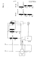
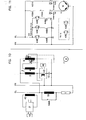
- Fig. 1 shows the simplified representation of the reactive power control device for a Einphasen-System.mit L as phase and N as midpoint or N eutralleiter.
- the system feeds a load 1, which is partially inductive and requires compensation with a leading reactive power.
- the reactive power caused by the load is called a reactive power measured sensor 2, which is connected in series with load 1.
- the reactive power compensation is achieved by a parallel circuit, which comprises a series transformer 3 with a fixed transformation ratio between the primary winding 4 and the secondary winding 5, a variable transformer 6 with two current collectors 7 and 8, a fuse 9 and a capacitor 10.
- the secondary winding 5 of the series transformer 3 with a fixed transformation ratio is connected in series with the fuse 9 and the capacitor 10.
- the primary winding 4 of the series transformer 3 is fed via the current collectors 7 and 8 of the variable transformer 6.
- the variable transformer 6 is a column transformer, the current collectors 7 and 8 are preferably equipped with carbon rollers that slide on the windings of the column transformer. These current collectors 7 and 8 are driven by a DC motor 11 via bevel gear and drive spindles in such a way that when the current collector 7 moves upwards, the current collector 8 moves in the opposite direction at the same speed.
- the current collectors 7 and 8 are offset by 180 ° on the circumference of the winding surface of the variable transformer 6, so that when the current collector 7 slides on the front of the winding surface, the current collector 8 slides in the opposite direction on the back of the winding surface.
- the variable transformer 6 is fed via the fixed connections of the network LN.
- both are on the same turn of the variable transformer 6, and the resulting voltage across the pantographs 7 and 8 becomes zero.
- the pantograph 7 has reached one end of the winding column, for example above, and accordingly, the current collector 8 has reached the lower end, the voltage between the current collectors 7 and 8 becomes equal to the mains voltage, and the mains voltage is fed into the primary winding 4 of the series transformer 3.
- This voltage induces a specific voltage in the secondary winding 5 of the series transformer 3, the voltage magnitude depending on the ratio of the primary winding 4 to the secondary winding 5.
- the voltage supplied to the capacitor 10 varies between the magnitude of the mains voltage and the highest available voltage from the secondary winding 5 of the series transformer 3.
- the voltage can be changed as desired, for example manually, by push button control or automatically by control loops 12, which are connected to the reactive power sensor 2 and the DC motor 11.
- the voltage change can be carried out in infinitely small steps in both cases and thereby generates an extremely precise compensating reactive power.
- the voltage supplied to the capacitor 10 and thus the compensating reactive power can be varied in a range that extends from maximum to down to zero. In practice, however, this lower limit is never required. This lower limit can advantageously be shifted upwards with the reactive power compensation device, as a result of which the size and consequently also the costs are reduced.
- a further cost saving is given by the possibility of using a capacitor 10 with a high nominal voltage. It is known that the higher the nominal voltage of the condenser 10, the lower its capacity in microfarat with the same power and consequently the lower price.
- FIG. 2A shows a variant, in which the variable transformer 6 is fed from a tap of the auxiliary winding 15 of the autotransformer 13, ie from a potential which is lower than in Fig. 2. The lowest practicable potential is the point at which the base winding 14 of the autotransformer 13 is connected to the additional winding 15.
- FIG. 2B shows a variant in which the variable transformer 6 is fed by a potential which is higher than that in FIG. 2.
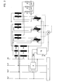
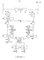
- Fig. 3 shows the same system as Fig. 2, but adapted to a three-phase four-wire network. All transformers should preferably be three-phase or ring type. Otherwise the mode of operation is the same as described in FIG. 2.
- the control loops 12 are the same as in FIGS. 1 and 2.
- the reactive power sensor 2 is shown in FIG. 2 in an embodiment which also applies to a balanced four-wire network.
- a reactive power sensor 2 corresponding to the design shown here must be used for uneven loads in the individual network phases L1, L2, L3.
- the reactive power sensor 2 has a simple current path in the interrupted line of the line phase L3. It also has three power supplies, one from the line phase L1 neutral, the second from line phase L2 to neutral and the third from line phase L3 to neutral. In a three-phase four-wire network with unbalanced load, these three voltage supplies are required, but also three current paths, which means that all three phases L1, L2, L3 are interrupted in the manner shown for phase L3. In contrast, in a three-phase three-wire network with balanced load, only one current path and only one voltage path are required.
- variable transformer 6 is designed as a ring variable transformer in an economy circuit with center tap.
- a variable ring transformer 6 offers the advantage that it is inexpensive on the one hand and commercially available on the other hand. However, it has only a limited power size and in the event of a parallel connection, the individual ring variable transformers 6 must be reduced in power.
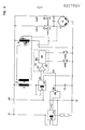
- FIG. 5 shows a solution in which the mains voltage remains within the low-voltage range, ie below 1.2 kV, while a capacitor 10 is provided as a high-voltage capacitor, for example 15 kV, for reasons of cost.
- the system is similar to the system shown in Figure 1, except that an step-up transformer 16 has been inserted with the primary winding 17 and the secondary winding 18, the primary winding 17 being the low voltage winding and the secondary winding 18 being the high voltage winding.
- the circuit of the secondary winding 18 is isolated from that of the primary winding 17 accordingly.
- the only disadvantage when using a step-up transformer 16 is the additional ones Costs for this transformer which are higher than for an autotransformer 13. However, these additional costs are fully or at least partially offset by the lower costs for the capacitor 10 for an even higher voltage than, for example, in FIG. 2.
- Fig. 6 shows a case where the line voltage is a high voltage, for example 15 kV.
- a variable transformer 6 with two windings, a primary high-voltage winding 19 and a secondary low-voltage winding 20, is used.
- FIG. 7 a two-winding transformer 21 with the primary high-voltage winding 19 and the secondary low-voltage winding 22 is provided in FIG. 7.
- the primary high-voltage winding 19 and the secondary low-voltage winding 2 feed the variable transformer 6, which is designed as a low-voltage transformer. With this arrangement, a lower voltage is applied to the capacitor 10 than is present in the network.
- the DC motor 1 drives the current collectors 7 and 8 (not shown here), that is to say current collectors 7 upwards and 8 downwards when the DC motor 11 rotates to the right, current collectors 8 up and 7 down when he turns left.
- the DC motor 11 causes clockwise (increasing) and left-rotating (decreasing) winding positions.
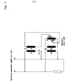
- the reactive power sensor 2 has two current terminals, which are inserted into the mains line L. It has two potential terminals, one is connected to the mains cable L, the other to neutral N.
- Transducers are omitted for simplicity and understanding, although in practice current sensing via a current transformer is essential and in many cases a voltage transformer is required.
- the feedback signal 23 generated by the reactive power sensor 2 is received by the reactive power controller 24.
- the reactive power controller 24 has a reference signal 25 fed by the control voltage L, N. This reference signal usually has 25 Z diodes
- the reactive power controller 24 further includes a feedback signal controller 26, which receives the feedback signal 23 from the reactive power sensor 2, a comparator 27 and a servo amplifier 28.
- the reference signal 25 and the feedback signal 23 are compared in the comparator 27 and a positive or negative error signal 29 is generated.
- the error signal 29 is then passed into the servo amplifier 28.
- the controlled and amplified signal either feeds the coil of relay K 30 (falling) or the coil of relay K 31 (rising).
- the coil of the K 30 relay is supplied, the corresponding K 30A make contact closes.
- the current from control voltage L flows via a normally closed limit switch 32 to that winding of the DC motor 11 which causes a counterclockwise rotation.
- the rotation of the DC motor 11 causes the pantograph 7 to slide down and the pantograph 8 to slide up, which causes a reduction in the voltage supplied to the capacitor 10.
- the rotation stops when the reactive power compensation - has reached the set value, and at this time the error signal 29 is almost zero, and as close to zero as permitted by the N enngenautechnik of the reactive power controller 24th If the error signal 29 becomes zero, the coil of the relay K 30 is de-energized, the corresponding contact K 30A opens and the feed line to the "left-turning" winding of the DC motor 11 is interrupted, the DC motor 11 stops, as well as the movement of the pantographs 7 and 8, the voltage change and the reactive power correction. After that, the process of power factor correction is practically complete. All of these processes also stop when the current collectors 7 and 8 reach their mechanical end position and thereby open the normally closed limit switches 32/33.
- the reactive power sensors 34 and 35 are used, which do not necessarily have to be of the same type.
- the reactive power sensor 34 is inserted into the load circuit and determines the magnitude of the reactive power caused by the load and whether it is leading or lagging.
- the reactive power sensor 35 is inserted into the parallel circuit for reactive power compensation and accordingly determines the size of the compensating reactive power and whether it is leading or lagging with respect to the mains voltage.
- the reactive power sensors 34 and 35 are each provided with a voltage sensor that ends in a voltage converter. For the sake of clarity, only the voltage sensor lines and their connections are shown in FIG. 9.
- the reactive power sensors 34 and 35 each have a current converter 36 and 37, which is shown as a coil.
- the reactive power sensor 34 is burdened by a potentiometer 38, as a result of which a given feedback signal 23 can be gradually reduced.
- the full feedback signal 23 indicates the total reactive power generated by the load.
- the consumer 39 of the potentiometer 38 is connected to one of the two inputs of the comparator 27.
- the system is arranged in such a way that when the customer 39 is fully adjusted, the corrected power factor becomes one. The further the customer 39 is removed from its "full exit" position, the lower the regulated power factor.
- the reactive power sensor 35 is inserted in the parallel circuit for the compensating reactive power. It generates a reference signal 25 which is compared in the comparator 27 with the feedback signal 23 from the consumer 39.
- the comparator 27 generates a positive or negative error signal 29 therefrom. With such an arrangement, a Z-diode controller can be dispensed with, which achieves higher accuracy.
- the reactive power caused by the load and the compensating reactive power are measured directly by the reactive power sensors 34 and 35 and compared with one another. Furthermore, this system is not dependent on the sinusoidal shape or the frequency of the mains voltage.
- the transmitter for the load is preferably a double transmitter and the same applies to the compensation circuit lying in parallel.
- the load transmitter is preferably a triple transmitter, while a double transmitter is sufficient for the parallel compensation circuit, even for uneven load.
- three single-phase reactive power compensation devices with three individual reactive power sensors are used per load or in parallel horizontal compensation circuit used.
- electromechanical relays K 30 and K 31 electronic relays can be used.
- the "up" - “down” relays are locked using auxiliary contacts to make the control circuit safe from switching.
- P-I-D proportional-integral-differential
- a microprocessor can of course also be used. This would then sample the lagging reactive power plus the leading reactive power using a three-point control,. in which the control process is interrupted until the ratio of the leading to the lagging reactive power has changed.
- a microcomputer can also be used for the control.
- Fig. 10 is a modification of the basic circuit of one phase of a three-phase system.
- a current converter 40 is inserted into the mains line L, the secondary winding of which feeds a commercially available AC converter 41.
- the AC converter 41 supplies a signal proportional to the load current of the mains line L to measuring devices 42, which are described in more detail in FIG. 12.
- an inductance 51 for resonance suppression is inserted into the mains supply line L, which is normally short-circuited via the contact of the contactor K 50A.
- a variable transformer 6 is inserted in an economy circuit, which feeds the primary winding 4 of the series transformer 3 with a fixed transformation ratio and whose secondary winding 5 is in turn connected in series with the capacitor 10.
- the current path of a reactive power sensor 43 the voltage path of which is connected to the terminals of the capacitor 10, is inserted in the circuit of the capacitor 10.
- another current transformer is inserted into the current path, which has been omitted here for the sake of clarity.
- the output of the reactive power sensor 43 supplies a signal which is proportional to the compensated reactive power and is fed to the measuring device 42 described in FIG. 12.
- FIG. 11 a further illustration of FIG. 9, shows the circuit of the DC motor 11, which drives the current collectors 7 and 8 of the variable transformer 6 in an economy circuit corresponding to FIG. 10 or FIG. 1.
- the coil of the relay K 30 has a normally open contact K 30A, which feeds the left-hand winding of the DC motor 11.
- the clockwise winding of the DC motor 11 is fed by the normally open contact K 31A of the coil of the relay K 31.
- a resonance threshold relay K44 receives a signal from the measuring devices 42 which is proportional to the differential quotient from the current square at the time.
- a normally closed contact K 44A of the resonance threshold relay K 44 inserted into the clockwise line of the DC motor 11, interrupts its clockwise function when a predetermined threshold is reached.
- a second normally closed contact K 44B of the resonance threshold relay K 44 feeds a resonance control relay K 46 at the same time in a separate circuit 45.
- the normally closed contact K 46A closes in a second separate circuit 47 and feeds a time delay relay K 48
- the predetermined delay time closes the normally closed contact K 48A of the time delay relay K 48 in a third separate circuit 49 and feeds the power contactor K 50.
- the resonance threshold relay K 44 has detected the resonance threshold of a dangerous initial value from the differential quotient of the current square over time and the normally closed contact K 44A has opened the danger is over.
- the power factor correction is stopped.
- the inductance 51 which is normally short-circuited via the normally closed contact K 50A of the power contactor K 50, as shown in FIG. 10, changes the reactance of the power line and thus prevents resonance.
- the coils of the resonance threshold relay K 44, the resonance control relay K 46 and the time delay relay K 48 are de-energized.
- the normally closed contact K 48A of the time delay relay K 48 remains closed, the power contactor K 50 continues to be supplied and its normally closed contact K 50A remains open.
- the normally closed contact K 44A remains closed, the normally closed contacts K 44B and K 46A remain open. This causes the "clockwise" movement of the DC electric motor 11 to be resumed and the process of improving the power factor to continue until the power factor has become one.
- An analog-to-digital converter 52 which is supplied by the AC converter 41, feeds a commercially available square circuit 53, the rectified output signal of which is proportional to the current square (I 2 ).
- the sampling rate of I 2 is relatively slow compared to the frequency of the network, for example two periods per second.
- a counter 54 samples I 2 at a rate sufficient to detect any changes in the average, for example at a rate of ten samples per second.
- An AND gate 55 which receives the I 2 signal, and an AND gate 56, which receives the signal of the reactive power sensor 43 digitized via an analog-digital converter 57, are both scanned by the counter 54.
- the output of the AND gate 55 which forms the I 2 signal sampled by the counter 54, feeds, on the one hand, directly to an input of a subtractor 58 and, on the other hand, to a second input of the subtractor 58 via a delay circuit, which is composed of a digital-to-analog converter 59 , a delay 60 and an analog-to-digital converter 61.
- the total delay of this delay circuit is 1 / f, where f is the sampling frequency of the counter 54. Accordingly, the subtractor 58 has at its output a signal which is proportional to the differential quotient from the current square at the time.
- an analog-to-digital converter 57 supplied by the reactive power sensor 43 feeds an AND gate 56 and an input of a subtractor 62 directly, while a second input of the subtractor 62 is fed via a delay circuit, which is composed of a digital-to-analog converter 63 , a delay 64 and an analog-to-digital converter 65.
- a signal appears at the output of the subtractor 62, which is proportional to the differential quotient from the reactive power over time.
- the output of subtractor 62 feeds an input of a commercially available logic divider 66, while the second input of logic divider 66 receives the output of subtractor 58 in such a way that a digitized signal appears at the output of logic divider 66 which is proportional to is the differential quotient from the current square to the reactive power.
- This digitized signal is converted by a digital-to-analog converter 67 into an analog signal.
- the output of the digital-to-analog converter 67 feeds the rectifiers 68 and 69 via an insulation circuit (not shown).
- the output of rectifier 68 gives a negative signal
- the output of rectifier 69 gives a positive signal. Turn feed these outputs': the coil of the relay K 30 and K 31st
- FIG. 13 shows a second embodiment for determining the differential quotient from the current square to the reactive power.
- the signal generated by the AC converter 41, FIG. 10 is digitized by the analog-to-digital converter 52 and made available to the input of a low-pass filter 70.
- the output of the low-pass filter 70 is fed to a sample and hold circuit 71.
- the Signal generated by the sampler and hold circuit 71 is supplied to an AND gate 74 via a current comparator 72 and a squarer 73.
- a second output of the low-pass filter 70 and a second output of the current comparator 72 are connected to a threshold element 75 for the lower threshold and a threshold element 76 for the upper threshold.
- the signal generated by the reactive power sensor 43 and digitized by the analog-digital converter 57 is made available to a low-pass filter 77.
- the output of the low-pass filter 77 is coupled to an AND gate 78.
- the counter 54 goes into a second input of the AND element 78 and of the AND element 74.
- the outputs of the AND elements 74 and 78 are connected to a programmable sequence controller 79, the connections to the disconnectors 32 and 33 and the resonance clamp relay K 44 has and consists of subtractors 80 and 81 and divider 82.
- the output signal of the programmable sequence controller 79 which is proportional to the differential quotient from the current square to the reactive power, is converted by a digital-to-analog converter 83 and applied to an optocoupler 84. If the signal is negative, it is connected to the input of relay K 30 via rectifier 68; if it is positive, it is connected to relay K 31 via rectifier 69.
Abstract
Description
Die Erfindung bezieht sich auf eine Blindleistungsregeleinrichtung zur Blindleistungskontrolle und Leistungsfaktorkorrektur, bestehend aus einer Blindleistungsausgleichsvorrichtung, die in Abhängigkeit einer induktiven oder kapazitiven Last im Netz mit vorgegebener Netzspannung über sich ändernden kapazitiven oder induktiven Einrichtungen eine kompensierende Blindleistung erzeugt.The invention relates to a reactive power control device for reactive power control and power factor correction, consisting of a reactive power compensation device which generates a compensating reactive power as a function of an inductive or capacitive load in the network with a predetermined network voltage via changing capacitive or inductive devices.
Eine Blindleistungsregeleinrichtung mit den im Oberbegriff des Hauptanspruchs angegebenen Merkmalen ist bekannt. Blindleistungen entstehen durch einer an das Netz angeschlossenen induktiven oder kapazitiven Last. Bei einer induktiven Last, zum Beispiel einem Elektromotor, erhält man eine nacheilende Blindleistung. Diese nacheilende Blindleistung wird durch Kondensatoren kompensiert, die eine vorauseilende Blindleistung liefern.A reactive power control device with the features specified in the preamble of the main claim is known. Reactive powers result from an inductive or capacitive load connected to the network. With an inductive load, for example an electric motor, one obtains a lagging reactive power. This lagging reactive power is compensated for by capacitors that provide leading reactive power.
Um eine ideale Kompensation zu erreichen, sollte die Größe der kompensierenden vorauseilenden Blindleistung der Größe der bestehenden nacheilenden Blindleistung gleichgesetzt werden, da das System sonst unter- oder überkompensiert wird. Um einer optimalen Kompensation so nahe wie möglich zu kommen, ist es bekannt, die erforderlichen, parallel zu schaltenden Kapazitäten aufzuteilen in eine Vielzahl von Kondensatoren, die durch Zu- und Abschaltung in dem Kreis parallel geschaltet sind. Diese Kondensatorschalttechnik stammt aus der Zeit vor 1918; hierbei wurden überwiegend 6 bis 9 parallel geschaltete Kondensatoren verwendet, welche durch Schütze geschaltet wurden, deren Spulen durch automatische Kontrolleinrichtungen gesteuert wurden, die wiederum durch Erfassen entweder des Leistungsfaktors oder des Verhältnisses von vorauseilendem zu nacheilendem $lindstrom oder vorauseilender zu nacheilender Blindleistung aktiviert wurden.In order to achieve ideal compensation, the size of the compensating leading reactive power should be set equal to the size of the existing lagging reactive power, otherwise the system will be under- or over-compensated. In order to get as close as possible to optimal compensation, it is known to divide the required capacitances to be connected in parallel into a large number of capacitors which are connected in parallel in the circuit by connection and disconnection. This capacitor switching technology dates from before 1918; predominantly 6 to 9 capacitors connected in parallel were used, which were switched by contactors, whose coils were controlled by automatic control devices, which in turn by detecting either the power factor or the ratio in advance rushing to lag behind the current or leading to lag behind the reactive power were activated.
Ein großer Nachteil dieser Kondensatorschalttechnik ist der, daß man zum Kompromiß gezwungen ist und einen Kompensationsgrad erreicht, der vom idealen Wert oder sogar von einem akzeptablen Wert abweicht. Bei Verwendung von 6 Kondensatoren zum Beispiel würde die Abweichung 1/12 des kompensierbaren Wertes betragen.A major disadvantage of this capacitor switching technique is that one is forced to compromise and achieve a degree of compensation that deviates from the ideal value or even from an acceptable value. For example, if 6 capacitors were used, the deviation would be 1/12 of the compensatable value.
Weiterhin nachteilig ist, daß eine Uberkompensation, also eine Leistungsfaktorkorrektur größer als 1,0, auftreten kann. Mit der Kombination von stufenweiser Zunahme der Kapazität und abrupter maximaler Stromschaltung könnte eine Überkompensation Überspannungen von 40% im Netz und nachfolgende Schäden an der Last, zum Beispiel an den Motorantriebseinrichtungen, unter bestimmten Betriebsbedingungen zur Folge haben.Another disadvantage is that overcompensation, that is to say a power factor correction greater than 1.0, can occur. With the combination of a gradual increase in capacity and an abrupt maximum current switching, overcompensation could result in overvoltages of 40% in the network and subsequent damage to the load, for example to the motor drive devices, under certain operating conditions.
Ein weiterer Nachteil liegt in der Kondensatorschaltung selbst. Bei Schaltung eines jeden Kondensators ergibt sich ein Stromstoß, eine Spitze oder ähnliches, welches extrem schädlich ist für empfindliche kritische elektronische Geräte, die an das Netz angeschlossen sind. Solche stromempfindlichen Geräte sind zum Beispiel Computer, bei denen sich als Hauptursache für Störungen die Kondensatorschaltung herausgestellt hat. Bei den heutigen Kondensatorschaltsystemen wird zwar die Zu- und Abschaltung der Kondensatoren im Spannungsnulldurchgang durchgeführt, aber hierdurch wird wenig erreicht, weil sich bei Kapazitäten die Stromamplitude im Maximum befindet, wenn die Spannungskurve durch Null geht und umgekehrt.Another disadvantage lies in the capacitor circuit itself. Switching each capacitor results in a surge, a peak or the like, which is extremely harmful for sensitive critical electronic devices that are connected to the network. Such current-sensitive devices are, for example, computers in which the capacitor circuit has been found to be the main cause of interference. In today's capacitor switching systems, the connection and disconnection of the capacitors is carried out at the zero voltage crossing, but little is achieved because the capacitance has the maximum current amplitude when the voltage curve goes through zero and vice versa.
Selbst bei Nichtvorhandensein von empfindlichen elektronischen Geräten verursacht die bisherige Methode der Kondensatorschaltung, die physikalisch gesehen rauh und heftig reagiert,.häufiges Auslösen der Kondensatorsicherungen. Dieses verursacht Leistungsverluste und erfordert dadurch eine Verbraucherleistungszunahme sowie Betriebskosten während der Ubergangsphase, bis die Sicherungen ersetzt sind.Even in the absence of sensitive electronic devices, the previous method of capacitor switching causes that from a physical point of view reacted roughly and violently, frequent tripping of the capacitor fuses. This causes performance losses and therefore requires an increase in consumer power and operating costs during the transition phase until the fuses are replaced.
Weitere Störungen treten bei dem bisherigen Stand der Tchnik auf, wenn der Verbraucher am Versorgungsnetz aus Gleichrichtern besteht, und zwar aus netzgeführten Stromrichtern, die bekannterweise eine sehr wesentliche Blindleistungskomponente und auch sehr wesentliche 5., 7. und 11. Oberwellen erzeugen. Es besteht die Gefahr, daß bei der Gleichrichter- Transformator- Wicklung bei einer bestimmten Schaltphase ein Resonanzkreis entsteht, dessen Frequenz dicht mit der Frequenz der 5. oder anderen ungeraden Oberwellen zusammentrifft und so die Stromzunahme in gefährlichem Maße unkontrollierbar wird.In the previous state of the art, further faults occur when the consumer on the supply network consists of rectifiers, namely line-guided converters which are known to produce a very important reactive power component and also very important 5th, 7th and 11th harmonics. There is a risk that in the rectifier-transformer winding a resonance circuit is formed in a certain switching phase, the frequency of which coincides closely with the frequency of the 5th or other odd harmonics and the current increase becomes dangerously uncontrollable.
Weiterhin nachteilig ist, daß die Kondensatoren mit Entladungswiderständen bestückt werden müssen. Bei Netzausfall oder einer Leistungsabschaltung oder Sicherungsauslösung, die häufig auftritt, bestand der Kreis ohne jegliche Entladung, und ohne die Entladungswiderstände würden die Kondensatoren bei der nächsten Belastung explodieren, wenn zur bestehenden Ladung eine weitere hinzugefügt wird. Die Entladungswiderstände haben neben den Beschaffungskosten den noch wesentlicheren Nachteil des ständigen Energieverbrauchs.Another disadvantage is that the capacitors must be equipped with discharge resistors. In the event of a power failure or a power cut or fuse trip that occurs frequently, the circuit would exist without any discharge, and without the discharge resistors, the capacitors would explode the next time the load was added, if another was added to the existing charge. In addition to the procurement costs, the discharge resistors have the even more significant disadvantage of constant energy consumption.
Ein weiterer Nachteil besteht in dem Unvermögen der Zurücksetzung des Grundanteils des Blindleistungskorrekturbereiches. Wenn man die Größe der zu korrigierenden Blindleistung untersucht, so ist die obere Grenze, nämlich die höchste vorauseilende Blindleistung, genau bestimmt. Bei der niedrigsten je benötigten Blindleistung sind selten Werte niedriger als 40% der höchsten Blindleistung erforderlich. Bei dem bisherigen Stand der Technik ist der Grundanteil jeglichen zu korrigierenden Blindleistungsbereiches immer Null, was unnötig und außerdem unangebracht ist.Another disadvantage is the inability to reset the base portion of the reactive power correction range. If one examines the magnitude of the reactive power to be corrected, the upper limit, namely the highest leading reactive power, is precisely determined. At the lowest reactive power required, values lower than 40% of the highest reactive power are rarely required. The basic part is in the previous state of the art Any reactive power range to be corrected is always zero, which is unnecessary and also inappropriate.
Weiterhin nachteilig ist die Tatsache, daß die Kondensatoren zu jeder Zeit bei voller Nennspannung arbeiten,und bei bestimmten Schaltstufen erhöht sich die Spitzenspannung über den Wert der Nennspitzenspannung der Kondensatoren, was diese Kondensatoren zerstören oder ihre Lebensdauer reduzieren kann.A further disadvantage is the fact that the capacitors operate at full nominal voltage at all times, and at certain switching stages the peak voltage increases above the value of the nominal peak voltage of the capacitors, which can destroy these capacitors or reduce their service life.
Der Erfindung liegt die Aufgabe zugrunde, eine Blindleistungsregeleinrichtung der eingangs beschriebenen Art so weiter zubilden, daß bei geringem baulichen Aufwand die kompensierende Blindleistung kontinuierlich geregelt werden kann und ein Leistungsfaktor von eins erreicht wird.The invention has for its object to develop a reactive power control device of the type described above so that the compensating reactive power can be controlled continuously with little construction and a power factor of one is achieved.
Erfindungsgemäß wird dies dadurch erreicht, daß die Blindleistungsausgleichsvorrichtung im Nebenschluß zum Netz geschaltet ist, mindestens eine feste kapazitive oder induktive Einrichtung und ein separates Versorgungsnetz beinhaltet, welches die Spannung für die kapazitive oder induktive Einrichtung liefert, wobei das separate Versorgungsnetz, in Abhängigkeit der im Netz vorhandenen Last, die an der kapazitiven oder induktiven Einrichtung angelegte Spannung automatisch fortlaufend stufenlos derart regelt, daß eine kompensierende Blindleistung erzeugt wird, die sich quadratisch mit der momentan angelegten Spannung ändert. Die kompensatorische Blindleistung des elektrischen Systems wird also durch Erhöhen oder Erniedrigen der den kapazitiven oder induktiven Einrichtungen zugeführten Spannung geregelt. Die Regelung der Spannung, und damit der kompensierenden Blindleistung, erfolgt stufenlos, wodurch Stromstöße Stromspitzen oder ähnliches im Netz vermieden werden.According to the invention, this is achieved in that the reactive power compensation device is connected in the bypass to the network, contains at least one fixed capacitive or inductive device and a separate supply network which supplies the voltage for the capacitive or inductive device, the separate supply network depending on the in the network existing load, the voltage applied to the capacitive or inductive device automatically continuously continuously such that a compensating reactive power is generated, which changes quadratically with the currently applied voltage. The compensatory reactive power of the electrical system is thus regulated by increasing or decreasing the voltage supplied to the capacitive or inductive devices. The regulation of the voltage, and thus the compensating reactive power, is infinitely variable, which prevents current surges or similar in the network.
Weiterhin kann durch die kontinuierliche Regelung ein Leistungsfaktor von eins erreicht werden, ohne Überspannungen im Netz, hervorgerufen durch die stufenweise Zuschaltung der induktiven oder kapazitiven Einrichtungen, zu erhalten.Furthermore, the continuous control enables a power factor of one to be achieved without overvoltages in the network caused by the gradual connection of the inductive or capacitive devices.
Bei erfindungsgemäßer Ausführung der Blindleistungregeleinrichtung kann die kompensierende Blindleistung in einem Bereicht variiert werden, der von Maximum bis herunter zu Null reicht. Es besteht weiterhin die Möglichkeit, die untere Grenze des Bereichs größer als Null zu wählen, wodurch die Größe der induktiven oder kapazitiven Einrichtung für die kompensierende Blindleistung reduziert werden kann und folglich die Kosten der Blindleistungsregeleinrichtung reduziert wird. Die untere Grenze des Bereichs liegt etwa bei 40% der maximal benötigten, kompensierenden Blindleistung. Eine den induktiven oder kapazitiven Einrichtungen zugeführte Spannung mit dem Wert Null, was gleichzusetzen ist mit dem Nichtvorhandensein einer eine Blindleistung hervorrufenden Last im Netz, ist niemals erforderlich. Das nachfolgende Beispiel veranschaulicht, in welchem Maße eine Größenreduzierung der Blindleistungsregeleinrichtung möglich ist:
- Es wird eine Last im Netz angenommen, die eine nacheilende Blindleistung erzeugt, also zum Beispiel ein Elektromotor. Das Netz ist einphasig und hat eine Leistung von 200 kVA, 60 Hz, 240 V, und benötigt eine maximale kompensierende Blindleistung von 100 kVAR. Bei Anwendung der in dem Stand der Technik bekannten Methode zur Blindleistungkompensation werden 9 Kondensatoren vorgesehen, wobei jeder eine Blindleistung von 11,1 kVAR bei 240 V besitzt. Die stufenweise Parallelschaltung der Kondensatoren bewirkt die folgenden' Blindleistungen: 0,0/11,1/22,2/33,3/44,4/55,5/66,6/77,7/88,8/99,9 kVAR, wobei die ersten 3 bis 4 Stufen nicht erforderlich sind. Nimmt man die jedoch weg, wird die Vorrichtung teurer, weil ein höherer Nennstrom geschaltet werden muß. Es ist weniger praktikabel, weil die Elemente nicht mehr austauschbar wären.
- A load is assumed in the network that generates lagging reactive power, for example an electric motor. The network is single-phase and has an output of 200 kVA, 60 Hz, 240 V, and requires a maximum compensating reactive power of 100 kVAR. When using the method for reactive power compensation known in the prior art, 9 capacitors are provided, each having a reactive power of 11.1 kVAR at 240 V. The stepwise parallel connection of the capacitors leads to the following reactive powers: 0.0 / 11.1 / 22.2 / 33.3 / 44.4 / 55.5 / 66.6 / 77.7 / 88.8 / 99.9 kVAR, with the first 3 to 4 stages not required are. However, if this is removed, the device becomes more expensive because a higher nominal current has to be switched. It is less practical because the elements would no longer be interchangeable.
Als 2. Beispiel wird die hier vorgeschlagene Blindleistungsregeleinrichtung benutzt. Es wird eine einzelne kapazitive Vorrichtung, also ein einzelner Kondensator,.mit einer Blindleistung von 100 kVAR bei 480 V verwendet. Solch ein Kondensator kostet ungefähr nur 1/4 eines einzelnen Kondensators mit einer Blindleistung von 100 kVAR bei 240 V oder sogar weniger im Vergleich zu 9 unterteilten Kondensatoren. Der Spannungsbereich des verwendeten Kondensators beträgt 480 V zu Null. Eine Hälfte dieser Blindleistung kommt direkt vom Netz, die andere Hälfte, d. h. 50 kVA, wird von dem separaten Versorgungsnetz geliefert.The reactive power control device proposed here is used as a second example. A single capacitive device, i.e. a single capacitor, with a reactive power of 100 kVAR at 480 V is used. Such a capacitor costs approximately 1/4 of a single capacitor with a reactive power of 100 kVAR at 240 V or even less compared to 9 divided capacitors. The voltage range of the capacitor used is 480 V to zero. Half of this reactive power comes directly from the network, the other half, i. H. 50 kVA, is supplied by the separate supply network.
.In dem folgenden Beispiel soll der Grundbereich der kompensierenden Blindleistung entfallen. Es wird ein Kondensator für 100 kVAR und 360 V verwendet. Die niedrigste dem Kondensator zugeführte Spannung sei 120 V, die höchste 360 V. Die Leistung des separaten Versorgungsnetzes beträgt dann 33,3 kVA. Dies ist eine Einsparung von 1/3 der Leistung. Jedoch ist der hier verwendete 360 V Kondensator treurer als der 480 V Kondensator bei gleicher Größe der Blindleistung von 100 kVAR.In the following example, the basic range of compensating reactive power is to be omitted. A capacitor for 100 kVAR and 360 V is used. The lowest voltage supplied to the capacitor is 120 V, the highest 360 V. The power of the separate supply network is then 33.3 kVA. This is a saving of 1/3 of the power. However, the 360 V capacitor used here is more trustworthy than the 480 V capacitor with the same reactive power of 100 kVAR.
Es können also Kondensatoren für höhere Nennspannungen verwendet werden. Es ist bekannt, je höher die Nennspannung des Kondensators ist, desto niedriger ist seine Kapazität in Mikrofarat für ein gegebenen kVA-Wert und folglich desto niedriger sein Preis.So capacitors for higher nominal voltages can be used. It is known that the higher the nominal voltage of the capacitor, the lower its capacitance in microfarat for a given kVA value and consequently the lower its price.
Es kann ein einzelner Kondensator, im Gegensatz zu mehreren Kondensatoren mit kleineren Werten, verwendet werden. Ein einzelner größerer Kondensator ist wirtschaftlicher hinsichtlich Kosten und Größe sowie Aufwand für Montage und Verdrahtung.A single capacitor can be used, as opposed to multiple capacitors with smaller values. A single larger capacitor is host more economical in terms of cost and size as well as effort for assembly and wiring.
Vorteilhaft braucht bei einer an die kapazitive Einrichtung angelegten kontinuierlich regelbaren Spannung keine Sicherung vorgesehen zu werden, da durch das Nichtvorhandensein von abruptem vorauseilendem Blindstromwechsel die Chance, daß solch eine Sicherung auslöst, gleich Null ist.In the case of a continuously controllable voltage applied to the capacitive device, there is advantageously no need to provide a fuse, since the absence of an abruptly leading change in reactive current means that the chance that such a fuse will trip is zero.
Das separate Versorgungsnetz besteht vorteilhaft aus einem Serientransformator mit isolierter Primär- und Sekundärwicklung und einem Stelltransformator, wobei die Sekundärwicklung des Serientransformators in Reihe mit der kapazitiven oder induktiven Einrichtung geschaltet und der Stelltransformator an das Netz angeschlossen ist. Mit einem Stelltransformator kann in einfacher Weise eine variable Spannung erzeugt werden. Die variable Spannung des Stelltransformators speist die Primärwicklung des Serientransformator,- Die Primärwicklung des Serientransformators induziert eine zweite variable Spannung in die Sekundärwicklung des Serientransformators. Die Spannung der Sekundärwicklung ist in Phase mit der Spannung des Netzes. Die Größe der induzierten Spannung ist abhängig von der Stellung des Stelltransformators und dem Übersetzungsverhältnis der Primär- zur Sekundärwicklung des Serientransformators. Die der induktiven oder kapazitiven Einrichtung für die kompensierende Blindleistung zugeführte Spannung variiert zwischen der Größe der Netzspannung und der höchsten verfügbaren Spannung der Sekundärwicklung des Serientransformators. Die Spannung kann nach Belieben in unendlich kleinen Schritten verändert werden und erzeugt dadurch extrem genaue Werte.The separate supply network advantageously consists of a series transformer with insulated primary and secondary windings and a variable transformer, the secondary winding of the series transformer being connected in series with the capacitive or inductive device and the variable transformer being connected to the network. A variable voltage can be generated in a simple manner with a variable transformer. The variable voltage of the variable transformer feeds the primary winding of the series transformer, - The primary winding of the series transformer induces a second variable voltage in the secondary winding of the series transformer. The voltage of the secondary winding is in phase with the voltage of the network. The size of the induced voltage depends on the position of the variable transformer and the transformation ratio of the primary to the secondary winding of the series transformer. The voltage supplied to the inductive or capacitive device for the compensating reactive power varies between the size of the mains voltage and the highest available voltage of the secondary winding of the series transformer. The voltage can be changed in infinitely small increments at will and thus generates extremely precise values.
Weiterhin ist die variable Spannung bei Verwendung eines Stelltransformators und eine Serientransformators frei von jeglichen Störungen.Furthermore, the variable voltage is free of any interference when using a variable transformer and a series transformer.
Vorteilhaft kann die Rückführsignalsteuerung auch aus einem Blindleistungssensor bestehen, der im separaten Versorgungsnetz eingefügt ist und die kompensierende Blindleistung anzeigt. Damit wird dann die kompensierende Blindleistung direkt mit der durch die Last hervorgerufenen Blindleistung verglichen. Durch die Verwendung eines Blindleistungssensors anstelle eines Z-Dioden- Reglers wird eine verbesserte Genauigkeit der Blindleistungskompensation erreicht, da ein z-Dioden- Regler, auch wenn er einwandfrei arbeitet, mit größeren Fehlern behaftet ist.The feedback signal control can advantageously also consist of a reactive power sensor, which is inserted in the separate supply network and indicates the compensating reactive power. This then directly compares the compensating reactive power with the reactive power caused by the load. By using a reactive power sensor instead of a Z- diode controller, an improved accuracy of the reactive power compensation is achieved, since a z-diode controller, even if it works properly, is associated with larger errors.
Vorteilhaft hängt die Genauigkeit des Systems nicht von der Sinusform oder der Frequenz der Netzspannung ab, im Gegensatz zu einem Regelsystem mit Leistungsfaktormeßeinrichtungen, welches frequenzempfindlich ist.The accuracy of the system advantageously does not depend on the sinusoidal shape or the frequency of the mains voltage, in contrast to a control system with power factor measuring devices, which is frequency-sensitive.
Vorteilhaft weist der Stelltransformator für jede Phase des Netzes eine Wicklungssäule auf, wobei jede Wicklungssäule eine gleiche Anzahl von Stromabnehmern hat, die um 180° versetzt auf dem Umfang der Wicklungsoberfläche angeordnet sind und von denen jeweils die Hälfte in entgegengesetzter Richtung läuft und für jede Phase des Netzes eine kapazitive oder induktive Einrichtung vorgesehen ist. Die Richtungen, in denen die Stromabnehmer auf dem Stelltransformator geführt werden, sind umkehrbar. Somit ist eine unendliche Variation der Größe und eine Polaritätsumkehr der variablen Spannung im separaten Versorgungsnetz möglich.The variable transformer advantageously has a winding column for each phase of the network, each winding column having an equal number of current collectors, which are arranged offset by 180 ° on the circumference of the winding surface and of which half runs in the opposite direction and for each phase of the Network a capacitive or inductive device is provided. The directions in which the current collectors are guided on the variable transformer are reversible. This enables an infinite variation in size and a polarity reversal of the variable voltage in the separate supply network.
Vorteilhaft weist das separate Versorgungsnetz Regelschleifen auf, die einen Blindleistungssensor und einen Blindleistungsregler beinhalten, wobei der Blindleistungssensor ein Rückführsignal erzeugt, welches proportional der durch die Last im Netz hervorgerufenen Blindleistung ist und der Blindleistungsregler aus einer Rückführsignalsteuerung, die ein der kompensierenden Blindleistung proportionales Referenzsignal erzeugt, einer Komparatoreinrichtung, die das Rückführ- und Referenzsignal vergleicht und in Abhängigkeit davon ein Fehlererkennungssignal bildet und einem Servoverstärker, der in Abhängigkeit vom Fehlererkennungssignal den Stelltransformator regelt, besteht.The separate supply network advantageously has control loops which contain a reactive power sensor and a reactive power controller, the reactive power sensor generating a feedback signal which is proportional to the reactive power caused by the load in the network and the reactive power controller from a feedback signal controller which generates a reference signal proportional to the compensating reactive power. a comparator which compares the return and reference signal and provides in response thereto an error detection signal and a ervoverstärker S, which controls the regulating transformer in dependence on the error detection signal is.
Diese Regelschleifen bieten vorteilhaft die Möglichkeit, daß die Blindleistungsregeleinrichtung voll automatisch betrieben werden kann. Natürlich ist auch die Möglichkeit vorgesehen, manuel in die Regeleinrichtung einzugreifen. Bei voll automatischem Betrieb wird die kompensatorische Blindleistung fortlaufend stufenlos derart geregelt, daß sie die im Netz vorhandene, durch die Last hervorgerufene, Blindleistung praktisch vollständig kompensiert. Die Genauigkeit der Kompensation ist dabei abhängig von der Nenngenauigkeit des Blindleistungsreglers.These control loops advantageously offer the possibility that the reactive power control device can be operated fully automatically. Of course, the possibility is also provided to intervene manually in the control device. In fully automatic operation, the compensating reactive power is continuously regulated in such a way that it virtually completely compensates for the reactive power present in the network caused by the load. The accuracy of the compensation depends on the nominal accuracy of the reactive power controller.
Die Rückführsignalsteuerung, die ein der kompensierenden Blindleistung proportionales Referenzsignal erzeugt, kann aus einem Z-Dioden- Regler bestehen. Der Z-Dioden- Regler wird von der Regelspannung gespeist und weist Z-Dioden und am Ausgang eine Potentiometereinstellung auf.The feedback signal control, which generates a reference signal proportional to the compensating reactive power, can consist of a Z-diode controller. The Zener diode regulator is powered by the control voltage and has Zener diodes and a potentiometer setting at the output.
Vorteilhaft ist die feste kapazitive Einrichtung ein einzelner Kondensator, der eine höhere Nennspannung als das Netzes haben kann. Dadurch werden die Kosten der Blindleistungsregeleinrichtung reduziert, da der Preis für einen Kondensator pro kVA sehr-viel niedriger ist, wenn die Nennspannung erhöht wird. Dies ist insbesondere dann wirtschaftlich, wenn eine hohe kompensierende Blindleistung erforderlich ist.The fixed capacitive device is advantageously a single capacitor, which can have a higher nominal voltage than the network. This reduces the costs of the reactive power control device, since the price for a capacitor per kVA is very much lower if the nominal voltage is increased. This is particularly economical when a high compensating reactive power is required.
Vorteilhaft ist dem Servoverstärker ein DC-Motor nachgeschaltet. Der Elektromotor wird vom Servoverstärker gesteuert und verschiebt seinerseits die Stromabnehmer des Stelltransformators. Durch die Verwendung eines umkehrbaren DC-Motors können die Stromabnehmer mit variabler Geschwindigkeit verfahren und dynamisch gebremst werden. Dies gewährleistet die schnelle Reaktion der Blindleistungsregeleinrichtung auf Änderungen der im Netz vorhandenen, durch eine Last hervorgerufenen, Blindleistung.A DC motor is advantageously connected downstream of the servo amplifier. The electric motor is controlled by the servo amplifier and in turn moves the current transformer's pantographs. By using a reversible DC motor, the pantographs can be moved at variable speeds and braked dynamically. This ensures that the reactive power control device reacts quickly to changes in the reactive power in the network caused by a load.
Vorteilhaft weist das separate Versorgungsnetz weiterhin einen Spartransformator in Zu- und Gegenschaltung auf, der vom Netz gespeist wird und dessen Ausgang vor die Sekundärwicklung des Serientransformators geschaltet ist. Die an dem Kondensator angelegte Spannung kann mit Hilfe des Spartransformators, entsprechend den vorliegenden Gegebenheiten, verschoben werden. Die Kondensatorspannung kann wesentlich höher als die verfügbare Netzspannung gewählt werden. Dies ist insoweit wichtig, da aus Kostengründen ein Kondensator mit höherer Nennspannung als die verfügbare Netzspannung bevorzugt wird. Der Spartransformator beinhaltet eine Grundwicklung und eine Zusatzwicklung. Die höchste Spannung, die mit der Kondensatornennspannung gleichgesetzt werden muß und die die höchste vorauseilende Blindleistung ergibt, ist gleich der Spannung: Spannung der Zusatzwicklung zu neutral plus Spannung der Zusatzwicklung zu neutral dividiert durch das Verhältnis der Windungen der Primärwicklung zu den Windungen der Sekundärwicklung des Serientransformators. Die niedrigste, mit dieser Einrichtung erreichbare Spannung, die die niedrigste verfügbare vorauseilende Blindleistung erzeugt, ist gleich: Spannung der Zusatzwicklung zu neutral minus Spannung der Zusatzwicklung zu neutral dividiert durch das Verhältnis der Windungen der Primärwicklung zu den Windungen der Sekundärwicklung des Serientransformators. Die höchste Spannung kann zum Beispiel fünfmal so hoch wie die Netznennspannung gewählt werden, wenn die di-elektrischen Umstände und die elektrischen Bestimmungen es zulassen.Advantageously, the separate supply network also has an autotransformer in connection and back-up connection, which is fed by the network and the output of which is connected upstream of the secondary winding of the series transformer. The voltage applied to the capacitor can be shifted with the help of the autotransformer in accordance with the present circumstances. The capacitor voltage can be chosen significantly higher than the available mains voltage. This is important because, for reasons of cost, a capacitor with a higher nominal voltage than the available mains voltage is preferred. The autotransformer includes a basic winding and an additional winding. The highest voltage that must be equated with the nominal capacitor voltage and that yields the highest leading reactive power is equal to the voltage: voltage of the additional winding to neutral plus voltage of the additional winding to neutral divided by the ratio of the turns of the primary winding to the turns of the secondary winding of the series transformer. The lowest voltage achievable with this device, which generates the lowest available leading reactive power, is the same: voltage of the additional winding to neutral minus voltage of the additional winding to neutral divided by the ratio of the turns of the primary winding to the turns of the secondary winding of the series transformer. The highest voltage can be selected, for example, five times as high as the nominal network voltage if the di-electrical circumstances and the electrical regulations allow it.
Ist das Netz ein Niederspannungsnetz mit einer kleineren Spannung als 1,2 kV und ist mindestens eine kapazitive Einrichtung eine feste kapazitive Einrichtung für eine Hochspannung von insbesondere 15 kV, so beinhaltet vorteilhaft das separate Versorgungsnetz weiterhin einen Aufwärtstransformator, der von dem Niederspannungsnetz gespeist wird und dessen Ausgang vor die Sekundärwicklung des Serientransformators geschaltet ist. Damit ist eine Erhöhung der an den Kondensator angelegten Spannung möglich, wobei eine sehr hohe Blindleistung kompensierbar wird. Die Kondensatornennspannung kann, im Vergleich zu der Kondensatornennspannung bei Verwendung eines Spartransformators, noch höher gewählt werden. Die zusätzlichen Kosten für einen weiteren Transformator mit zwei Wicklungen, also für einen Aufwärtstransformator, werden ganz oder zumindest teilweise ausgeglichen durch die niedrigeren Kosten für den Kondensator mit einer sehr hohen Nennspannung.If the network is a low-voltage network with a voltage lower than 1.2 kV and at least one capacitive device is a fixed capacitive device for a high voltage of in particular 15 kV, then the separate supply network advantageously also contains an step-up transformer which is fed by the low-voltage network and the latter Output is connected before the secondary winding of the series transformer. This makes it possible to increase the voltage applied to the capacitor, and a very high reactive power can be compensated for. The nominal capacitor voltage can be chosen to be even higher compared to the nominal capacitor voltage when using an autotransformer. The additional costs for a further transformer with two windings, that is to say for a step-up transformer, are fully or at least partially offset by the lower costs for the capacitor with a very high nominal voltage.
Hat das Netz eine höhere Spannung als 1,2 kV, also ab 1,2 kV bis 380 kV, so ist die Primärwicklung des Serientransformators vorteilhaft eine Niederspannungswicklung und der Stelltransformator weist zwei voneinander isolierte Wicklungen auf, von denen eine eine mit dem Netz parallel geschaltete Primärhochspannungswicklung ist, und die andere Wicklung des Stelltransformators eine Sekundärniederspannungswicklung mit variablem Ausgang ist, die die Primärwicklung des Serientransformators speist. Durch die Verwendung eines Stelltransformators mit zwei isolierten Wicklungen kann die dem Kondensator zugeführte Spannung kleiner als die Netz - Nennspannung gewählt werden. Es kann somit ein Kondensator mit kleinerer Nennspannung als der Netzspannung verwendet werden, um die Kosten zu reduzieren. Ein Kondensator mit kleinerer Nennspannung als der Netzspannung erweist sich insbesondere dann als kostengünstiger, wenn die zu kompensierende Blindleistung relativ gering ist.If the network has a higher voltage than 1.2 kV, i.e. from 1.2 kV to 380 kV, the primary winding of the series transformer is advantageously a low-voltage winding and the variable transformer has two windings insulated from each other, one of which is connected in parallel with the network Primary high voltage winding, and the other winding of the variable transformer is a secondary low voltage winding with variable output, which feeds the primary winding of the series transformer. By using a variable transformer with two insulated windings, the voltage supplied to the capacitor can be selected to be less than the nominal mains voltage. A capacitor with a nominal voltage lower than the mains voltage can thus be used in order to reduce the costs. A capacitor with a smaller nominal voltage than the mains voltage proves to be more cost-effective in particular if the reactive power to be compensated for is relatively low.
Hat das Netz eine höhere Spannung als 1,2 kV, dann ist der Stelltransformator vorteilhaft ein Niederspannungsspartransformator, die Primärwicklung des Serientransformators eine Niederspannungswicklung und das separate Versorgungsnetz beinhaltet einen isolierten Zwei-Wicklungen-Transformator mit festem Übersetzungsverhältnis, dessen Primärhochspannungswicklung parallel zum Netz geschaltet ist und dessen Sekundärniederspannungswicklung den Stelltransformator speist. Dies ist eine alternative Einrichtung zu einem Stelltransformator, der von einer Primärhochspannungswicklung gespeist wird, wie oben beschrieben. Auch hier ist es möglich, einen Kondensator zu verwenden, dessen Nennspannung kleiner als die Netzspannung ist. Entsprechend den Gegebenheiten kann bei Vorhandensein eines Hochspannungsnetzes und einer kleinen zu kompensierenden Blindleistung die eine oder andere Alternative Anwendung finden.If the network has a higher voltage than 1.2 kV, the variable transformer is advantageously a low-voltage saving transformer, the primary winding of the series transformer is a low-voltage winding and the separate supply network contains an insulated two-winding transformer with a fixed transformation ratio, the primary high-voltage winding of which is connected in parallel to the network and whose secondary low-voltage winding feeds the variable transformer. This is an alternative to a variable transformer powered by a primary high voltage winding as described above. Here, too, it is possible to use a capacitor whose nominal voltage is lower than the mains voltage. Depending on the circumstances, one or the other alternative can be used in the presence of a high-voltage network and a small reactive power to be compensated.
Vorteilhaft ist ein vom Netz gespeistes Einschaltregelsystem vorgesehen, daß aus Spannungsmeßeinrichtungen mit nachgeschalteten Regeleinrichtungen, aus Freigabeeinrichtungen und Nachfolgeeinrichtungen besteht, wobei die Spannungsmeßeinrichtungen mit den Regeleinrichtungen den Stelltransformator vom Netz trennen, wenn die Leistung des Netzes abgeschaltet wird, wobei dann der Stelltransformator zu einer dämpfenden Last für die Primärwicklung des Serientransformators wird und die Sekundärwicklung des Serientransformators zu einer Primärwicklung und die Primärwicklung die Serientransformators zu einer Sekundärwicklung wird, wobei gleichzeitig zu dem Trennen des Stelltransformators von dem Netz die Regelschleifen des separaten Versorgungsnetzes außer Betrieb gesetzt werden, wodurch keine weitere kompensierende Blindleistung erzeugt wird; die Freigabeeinrichtungen in Verbindung mit den Nachfolgeeinrichtungen beim Einschalten der Leistung des Netzes den Stelltransformator auf die kleinste mögliche Spannung einstellen, den Stelltransformator wieder an das Netz anschließen, wobei nachfolgend die Primär- und Sekundärwicklung des Serientransformators wieder entsprechend ihrer ursprünglichen Bestimmung geschaltet werden, die Nachfolgeeinrichtungen die Regelschleifen des separaten Versorgungsnetzes wieder freigeben und wieder eine kontinuierlich geregelte kompensierende Blindleistung erzeugt wird. Damit wird sichergestellt, daß die Spannung, die dem Kondensator zugeführt wird, zum Zeitpunkt der Leistungseinschaltung so niedrig wie möglich eingestellt wird. Das Einschaltregelsystem verhindert ein explodieren der Kondensatoren, wenn zum Beispiel nach einem Netzausfall die Blindleistungsregeleinrichtung wieder aktiviert wird. Ohne dem Einschaltregelsystem würde dem Kondensator zu der bestehenden Ladung eine weitere zugefügt werden, wodurch der Kondensator überlastet und letztendlich zerstört werden würde.Advantageously, a start-up control system powered by the network is provided, which consists of voltage measuring devices with downstream control devices, release devices and successor devices, the voltage measuring devices with the control devices separating the variable transformer from the network when the power of the network is switched off, in which case the variable transformer becomes a damping load for the primary winding of the series transformer and the secondary winding of the series transformer becomes a primary winding and the primary winding the series transformer becomes a secondary winding, with the control loops of the separate supply network being deactivated at the same time as the variable transformer is disconnected, as a result of which no further compensating reactive power is generated becomes; the enabling devices in connection with the successor devices set the variable transformer to the lowest possible voltage when the power of the network is switched on, reconnect the variable transformer to the mains, with the primary and secondary windings of the series transformer subsequently being switched again according to their original purpose, the successor devices Enable control loops of the separate supply network again and a continuously regulated compensating reactive power is generated again. This ensures that the voltage supplied to the capacitor is set as low as possible at the time the power is turned on. The switch-on control system prevents the capacitors from exploding if, for example, the reactive power control device is reactivated after a power failure. Without the switch-on control system, the capacitor would be added to the existing charge, thereby overloading the capacitor and would eventually be destroyed.
Vorteilhaft sind Meßeinrichtungen und Kontrolleinrichtungen vorgesehen, wobei die Meßeinrichtungen mit dem Netz verbunden sind und ein Signal erzeugen, welches proportional dem Differentialquotienten aus dem Stromquadrat zu der durch die Last hervorgerufenen Blindleistung ist, die Kontrolleinrichtungen mit Meßeinrichtungen und den Regelschleifen des separaten Versorgungsnetzes verbunden sind und die kompensierende Blindleistung derart regeln, daß der Differentialquotient aus dem Stromquadrat zu der durch die Last hervorgerufenen Blindleistung praktisch immer Null ist, wobei die Meßeinrichtungen Abtasteinrichtungen zur Ermittlung des im Netz fließenden Stromquadrates und der kompensierenden -Blindleistung, mit dem Netz verbundene Differentialmeßeinrichtungen zur Ermittlung des im Netz fließenden Stromquadrates über die Zeit, mit der Blindleistungsausgleichseinrichtung verbundene Differentialmeßeinrichtungen zur Ermittlung der kompensierenden Blindleistung über die Zeit und an den Differential - Meßeinrichtungen angeschlossene logische Schaltkreise einschließlich Teilereinrichtung, die ein zu dem Differentialquotienten aus dem Stromquadrat zu der durch die Last hervorgerufene Blindleistung proportionales Signal liefern, beinhalten und die Differentialen meßeinrichtung vorzugsweise aus Meßumformern, Analog/Digital- und Digital/Anlogwandler, Verzögerungseinrichtungen und Subtraktoren bestehen. Mit den Meßeinrichtungen und Kontrolleinrichtungen wird eine Regelung auch bei nicht sinusförmiger Spannung erreicht, wobei als Kriterium für die Regelung der Differentialquotient aus dem Stromquadrat zu der durch die Last hervorgerufenen Blindleistung Null gesetzt,wird. Bei den vorhergehenden Erläuterungen hat man stillschweigend vorausgesetzt, daß das beschriebene Gerät mit der Grundfrequenz des speisenden Generators des Elektrizitätsversorgungsunternehmens arbeitet. Unter diesen Bedingungen kann ein Leistungsfaktorregelsystem mit stufenloser Regelung zur Aufrechterhaltung eines konstanten Leistungsfaktors von 1,00 mit einer Genauigkeit von 0,25% eingesetzt werden. Einen Leistungsfaktor von 1,00 zu erreichen, ist bedeutend, jedoch nur mit sinusförmigen Spannungen, d. h. Spannungen, die von der Sinusform mit nicht mehr als 2% Oberwellenanteil abweichen.Measuring devices and control devices are advantageously provided, the measuring devices being connected to the network and generating a signal which is proportional to the differential quotient from the square of the current to the reactive power caused by the load, the control devices being connected to measuring devices and the control loops of the separate supply network, and the Regulate compensating reactive power in such a way that the differential quotient from the current square to the reactive power caused by the load is practically always zero, the measuring devices scanning devices for determining the square of the current flowing in the network and the compensating reactive power, differential measuring devices connected to the network for determining the network flowing current square over time, differential measuring devices connected to the reactive power compensation device for determining the compensating reactive power over time and to the difference ential - measuring devices connected logic circuits including dividing device, which supply a signal proportional to the differential quotient from the current square to the reactive power caused by the load, and the differential measuring device preferably consist of transducers, analog / digital and digital / analog converters, delay devices and subtractors . With the measuring devices and control devices, regulation is achieved even with a non-sinusoidal voltage, the criterion for the regulation being the differential quotient from the current square to that caused by the load Reactive power is set to zero. In the preceding explanations, it has been tacitly assumed that the device described operates at the fundamental frequency of the supply generator of the electricity supply company. Under these conditions, a power factor control system with stepless control can be used to maintain a constant power factor of 1.00 with an accuracy of 0.25%. Achieving a power factor of 1.00 is important, but only with sinusoidal voltages, ie voltages that deviate from the sinusoidal shape with no more than 2% harmonic content.
In heutigen Netzen sind Belastungen in vielen Fällen nicht linear aufgrund des Einsatzes von netzgeführten Stromrichtern, Thyristorgleichrichtern, unterbrechungsfreien Stromversorgungen und anderen nicht linearen Schaltkreisen. Außerdem ist die Leistungsversorgung der Uberlandleitungen unter den heutigen Bedingungen häufig nicht sinusförmig. Durch diese veränderten Bedingungen hat man es zusätzlich noch mit Oberwellen der Grundfrequenz zu tun. Hier geht es nicht mehr um einen Geräteleistungsfaktor, sondern um nichtlinearen Lasten und nicht sinusförmige Spannungsversorgungen zu den Belastungen.In today's networks, loads are in many cases non-linear due to the use of line-commutated converters, thyristor rectifiers, uninterruptible power supplies and other non-linear circuits. In addition, the power supply for the overhead lines is often not sinusoidal under today's conditions. Due to these changed conditions, one also has to deal with harmonics of the fundamental frequency. This is no longer about a device performance factor, but about non-linear loads and non-sinusoidal power supplies for the loads.
Dadurch bedingt hat man es nicht mit einer einzelnen Frequenz zu tun, sondern mit einer Vielzahl von Frequenzen, nämlich Oberwellen der Grundfrequenz. Die Minimierung des Energieverlustes auf Überlandleitungen und die Minimierung des Leistungsbedarfes und die Maximierung der verfügbaren Leistung wird erreicht, in dem das Verhältnis des Differentials des in der Netzleitung fließenden Stromquadrates (I2)zum Differential der kompensierenden Blindleistung (VAR) gleich Null gesetzt wird; mathematisch ausgedrückt: dI2/dVAR gleich Null, wobei I der gesamte, in der Überlandleitung zur Last fließende Strom ist, plus des zur Blindleistungsausgleichsvorrichtung fließenden Stromes. Das Quadrat dieses Stromes ist proportional zum tatsächlichen Wattverlust in der Netzleitung. VAR ist die Blindleistung, die durch die Blindleistungregeleinrichtung kompensiert werden soll. Daher setzt diese Erfindung neue Kriterien zur Minimierung von Leistungsverlusten auf Überlandleitungen bei nicht linearen Lasten oder von nicht sinusförmigen Spannungen der Stromversorgung - als Ersatz zur Erlangung eines Gerätefaktors "gleich eins" für lineare Lasten oder zur Leistungsversorgung mit sinusförmigen Spannungen.This means that you are not dealing with a single frequency, but with a multitude of frequencies, namely harmonics of the fundamental frequency. The minimization of the energy loss on overhead lines and the minimization of the power requirement and the maximization of the available power is achieved by setting the ratio of the differential of the current square flowing in the mains line (I 2 ) to the differential of the compensating reactive power (VAR) to zero; Expressed mathematically: dI 2 / dVAR equals zero, where I is the total current flowing in the overhead line to the load, plus the current flowing to the reactive power compensation device. The square of this current is proportional to the actual watt loss in the power line. VAR is the reactive power that is to be compensated for by the reactive power control device. Therefore, this invention sets new criteria for minimizing power losses on land lines with non-linear loads or non-sinusoidal voltages of the power supply - as a replacement for obtaining a device factor "equal to one" for linear loads or for power supply with sinusoidal voltages.
Vorteilhaft sind Einrichtungen zur Ermittlung einer entstehenden Anfangsresonanz, zur Resonanzunterdrückung und Abschalteinrichtungen zum Stoppen der Zunahme der kompensierenden Blindleistung vorgesehen, wobei die Einrichtungen zur Ermittlung einer entstehenden Anfangsresonanz an das Netz angeschlossen sind und ein Resonanzschwellenrelais, ein Resonanzkontrollrelais und ein Zeitverzögerungsrelais beinhalten, daß das Resonanzschwellenrelais zwei Ruhekontakte aufweist, wobei der erste Ruhekontakt bei Aktivierung der Einrichtungen zur Ermittlung einer entstehenden Anfangsresonanz den Stromkreis des DE-Motors für eine Zunahme der kompensierenden Blindleistung unterbricht, der zweite Ruhekontakt in Reihe geschaltet ist mit dem Resonanzkontrollrelais, ein Ruhekontakt des Resonanzkontrollrelais in Reihe geschaltet ist mit dem Zeitverzögerungsrelais vorgewählter Verzögerungszeit; die Einrichtungen zur Resonanzunterdrückung eine in das Netz eingefügte Induk- tivität und einen Leistungsschütz beinhalten, der Leistungsschütz einen Arbeitskontakt aufweist, der in Reihe mit dem Arbeitskontakt des Zeitverzögerungsrelais geschaltet ist und normalerweise die Induktivität kurzschließt, bei Energiezufuhr nach Ablauf der vorgewählten Verzögerungszeit das Zeitverzögerungsrelais diesen Kurzschluß beseitigt. Damit wird die zerstörerische Serienresonanz zwischen der Überlandleitung dund dem Kondensator vermieden und ein kontinuierlicher und sicherer Betrieb ermöglicht.Devices for determining an emerging initial resonance, for suppressing resonance and shutdown devices for stopping the increase in compensating reactive power are advantageously provided, the devices for determining an emerging initial resonance being connected to the network and comprising a resonance threshold relay, a resonance control relay and a time delay relay such that the resonance threshold relay contains two Has break contacts, the first break contact when activating the devices for determining an emerging initial resonance the circuit of the DE motor for an increase in compensating reactive power interrupts, the second normally closed contact is connected in series with the resonance control relay, a normally closed contact of the resonance control relay is connected in series with the time delay relay preselected delay time; the devices for suppressing resonance include an inductance inserted into the network and a power contactor, the power contactor has a make contact which is connected in series with the make contact of the time delay relay and normally short-circuits the inductor; when power is supplied after the preselected delay time, the time delay relay has this short circuit eliminated. This avoids the destructive series resonance between the overhead line and the capacitor and enables continuous and safe operation.
Die Erfindung wird anhand von bevorzugten Ausführungsbeispielen weiter beschrieben. Es zeigen:
- Fig. 1 das Grundschema der Blindleistungsregeleinrichtung, welches ein Einphasen-Wechselstromsystem betriebfähig macht,
- Fig. 2 ein Schema ähnlich Fig. 1, welches einen Zusatzspartransformator enthält, der eine Anpassung des Systems an eine wesentlich höhere Kondensatornennspannung und eine Reduzierung des unnötigen Grundanteils des Blindleistungskorrekturbereiches ermöglicht,
- Fig. 3 ein Schema ähnlich Fig. 2 für ein Drei-phasen-System,
- Fig. 4 eine alternative Lösung zu Fig. 1, welche einen Ringstelltransformator mit Mittelanzapfung enthält, um zu veranschaulichen, daß die Blindleistungsregeleinrichtung für begrenzte Leistungsbereiche auch mit sofort verfügbaren kommerziellen Komponenten realisiert werden kann,
- Fig. 5 ein Ausführungsbeispiel, wenn das Netz ein Niederspannungsnetz ist, d. h. die
Netzspannung kleiner als von größer als - Fig. 6 ein Ausführungsbeispiel, bei dem das Netz ein Hochspannungsnetz ist, die Netzspannung jedoch 15 kV nicht überschreitet und der Stelltransformator ein Isoliertransformator mit zwei Wicklungen ist,
- Fig. 7 eine Alternative zu Fig. 6, bei der ein Niederspannungsspartransformator verwendet wird, dieser aber von einem Isoliertransformator mit zwei Wicklungen gespeist wird, wobei der Isoliertransformator mit dem Hochspannungsnetz verbunden ist,
- Fig. 8 die Regelschleifen für Fig. 1 bis Fig. 7,
- Fig. 9 eine Alternative zu Fig. 8,
- Fig. 10 ein Ausführungsbeispiel, angepaßt für nicht sinusförmige Spannungen und/oder nicht lineare Belastungen,
- Fig. 11 ein Regelschaltkreis zur Vermeidung von Resonanzerscheinungen,
- Fig. 12 ein Blockschaltbild eines Schaltkreises, um das Differential des Stromquadrates dividiert durch das Differential der Blindleistung zu ermitteln,
- Fig. 13 ein alternatives Blockschaltbild zu Fig. 12.
- 1 shows the basic diagram of the reactive power control device, which makes a single-phase AC system operational,
- 2 shows a diagram similar to FIG. 1, which contains an additional autotransformer, which enables the system to be adapted to a significantly higher nominal capacitor voltage and a reduction in the unnecessary basic portion of the reactive power correction range,
- 3 shows a schematic similar to FIG. 2 for a three-phase system,
- 4 shows an alternative solution to FIG. 1, which contains a variable ring transformer with a center tap to illustrate that the reactive power control device for limited power ranges can also be realized with immediately available commercial components,
- Fig. 5 shows an embodiment when the network is a low-voltage network, that is, the network voltage is less than 1.2 kV, but the reactive power to be compensated is so enormous that it is economical to use a capacitor with a nominal voltage of greater than 1.2 kV to be used, an insulating transformer with two windings being provided,
- 6 shows an exemplary embodiment in which the network is a high-voltage network, but the network voltage does not exceed 15 kV and the variable transformer is an insulating transformer with two windings,
- 7 shows an alternative to FIG. 6, in which a low-voltage saving transformer is used, but this is fed by an insulating transformer with two windings, the insulating transformer being connected to the high-voltage network,
- 8 shows the control loops for FIGS. 1 to 7,
- 9 shows an alternative to FIG. 8,
- 10 shows an embodiment adapted for non-sinusoidal voltages and / or non-linear loads,
- 11 is a control circuit to avoid resonance phenomena,
- 12 is a block diagram of a circuit to determine the differential of the current square divided by the differential of the reactive power.
- FIG. 13 shows an alternative block diagram to FIG. 12.
Die nachfolgenden Ausführungsbeispiele finden sowohl bei sinusförmiger Netzspannung und/oder linearen Belastungen, sowie bei nicht sinusförmiger Netzspannung und/oder nicht linearen Belastungen Anwendung. Zum besseren Verständnis wird eine kurze Übersicht gegeben, welche Ausführungsformen bei den jeweiligen Gegebenheiten vorteilhaft Anwendung finden.The following exemplary embodiments are used both for sinusoidal mains voltage and / or linear loads, and for non-sinusoidal mains voltage and / or non-linear loads. For a better understanding, a brief overview is given of which embodiments are advantageously used in the respective circumstances.
Bei sinusförmiger Netzspannung und/oder linearer Belastung, bei dem das Netz ein Einphasensystem ist, finden die Ausführungsbeispiele der Fig. 1, 2, 4, 5, 6 und 7 Anwendung. Es wird die durch die Last hervorgerufene Blindleistung, die meist nacheilend ist, von dem Blindleistungssensor gemessen und ein der Blindleistung proportionales Signal, das Rückführsignal, dem Blindleistungsregler zur Verfügung gestellt. In Verbindung mit einem Referenzsignal wird ein Fehlersignal ermittelt, welches einen Servoverstärker speist.In the case of sinusoidal mains voltage and / or linear load, in which the network is a single-phase system, the exemplary embodiments in FIGS. 1, 2, 4, 5, 6 and 7 are used. The reactive power caused by the load, which is usually lagging, is measured by the reactive power sensor and a signal proportional to the reactive power, the feedback signal, is made available to the reactive power controller. In connection with a reference signal, an error signal is determined which feeds a servo amplifier.
Der Servoverstärker wiederum regelt über einen DC-Motor die Stellung der Stromabnehmer des Stelltransformators und bestimmt damit die kompensierende Blindleistung.The servo amplifier in turn regulates the position of the current transformer's pantographs via a DC motor and thus determines the compensating reactive power.
Bei sinusförmiger Netzspannung und/oder linearer Belastung, wobei das Netz drei Phasen mit leitlich gleichen Belastungen hat, findet das Ausführungsbeispiel der Fig. 3 Anwendung. Das Prinzip der Regelung ist dasselbe wie bei einem Einphasensystem, die Regelung umfaßt hier jedoch die drei Phasen des Netzes. Die durch die Last hervorgerufene Blindleistung wird mittels eines Blindleistungssensors in nur einer Phase gemessen. Für jede Phase des Netzes ist ein separater Stelltransformator vorgesehen, deren Stromabnehmer von dem DC-Motor positioniert werden. Dieses System sollte bei ausgeglichener Phasenbelastung angewand werden, wie zum Beispiel in einzelnen oder mehreren Drei-Phasen-Asynchronmotoren oder in Synchromotoren. Falls der Strom nicht kompensiert ist, sollte der Blindleistungssensor anstelle eines Stromkreises drei Stromkreise haben. Mit seinem Ausgang führt der Blindleistungssensor dem Servoverstärker dann die dreiphasige Blindleistung zu, die als Rückführsignal für den Servoverstärker verwendet wird, der mit seinem Ausgang die Stellung des DC-Motors regelt, der die Drei-Phasen-Stromabnehmer des Drei-Phasen-Stelltransformators positioniert, um einen Drei-Phasen-Parallelmittelwert zu erzeugen. Dieses System eignet sich für dreiphasige Belastungen, die nicht ganz symmetrisch sein müssen.In the case of sinusoidal mains voltage and / or linear load, the network having three phases with conductively identical loads, the exemplary embodiment in FIG. 3 is used. The principle of regulation is the same as for a single-phase system, but here the regulation comprises the three phases of the network. The reactive power caused by the load is measured in only one phase using a reactive power sensor. A separate variable transformer is provided for each phase of the network, the current collectors of which are positioned by the DC motor. This system should be used when the phase load is balanced, such as in single or multiple three-phase asynchronous motors or in synchromotors. If the current is not compensated, the reactive power sensor should have three circuits instead of one circuit. With its output, the reactive power sensor then feeds the three-phase reactive power to the servo amplifier, which is used as a feedback signal for the servo amplifier, which regulates with its output the position of the DC motor that positions the three-phase pantographs of the three-phase variable transformer, to generate a three phase parallel mean. This system is suitable for three-phase loads that do not have to be completely symmetrical.
Bei sinusförmiger Netzspannung und drei Netzphasen, wobei die einzelnen Netzphasen total ungleiche Belastungen haben, findet das Ausführungsbeispiel der Fig. 1 Anwendung, wobei jedoch die dort dargestellte" Blindleistungsregeleinrichtung für jede einzelne Phase vorzusehen ist. Solche ungleichen Belastungen der einzelnen Phasen treten dann auf, wenn die gesamte am Netz angeschlossene Last aus separaten, unabhängigen, hochinduktiven, individuellen Lasten mit geringem Leistungsfaktor besteht. Dies tritt beispielsweise bei Nahtschweißanlagen (Widerstandsschweißung) auf, wenn die Nahtschweißanlagen aus einzelnen Widerstandsschweißeinrichtungen bestehen, in denen jede einzelne Einphasen-Last einen Leistungsfaktor von nur 0,4 bis 0,6 hat und in denen jede einzelne Einphasen-Last Spannungsabfall, Wattverluste und Reduzierung der verfügbaren Betriebsleistung hervorruft. Durch die individuelle Kompensation der durch die Last hervorgerufenen Blindleistung in den einzelnen Phasen können bedeutende Energieeinsparungen und eine wesentliche Erhöhung der verfügbaren Betriebsleistung erreicht werden.In the case of sinusoidal line voltage and three line phases, the individual line phases having totally unequal loads, the embodiment of FIG. 1 is used, but the "reactive power control device shown there must be provided for each individual phase. Such unequal loads of the individual phases occur when the entire load connected to the network consists of separate, independent, highly inductive, individual loads with a low power factor. This occurs, for example, in seam welding systems (resistance welding), if the seam welding systems consist of individual resistance welding devices in which each individual single-phase load has a power factor of only 0.4 to 0.6 and in which each individual single-phase load causes voltage drop, wattage losses and a reduction in the available operating power. By individually compensating the reactive power caused by the load in the individual phases, significant energy savings and a substantial increase in the available operating power can be achieved.
Bei nicht sinusförmigen Netzspannungen und nicht linearen Belastungen kann prinzipiell das in Fig. 1 dargestellte separate Versorgungsnetz verwendet werden, wobei die Regelschleifen entsprechend Fig. 10, 11 und in der Ergänzung Fig. 12 sowie alternativ Fig. 13 auszuführen sind. Bei nicht sinusförmiger Netzspannung und/oder bei nicht linearen Lasten führt der Geräteleistungsfaktor nicht mehr zur Optimierung von Leistungsverbrauch, Leistungsbedarf und Leistungsverfügbarkeit. Daher sollte bei nicht sinusförmiger Netzspannung und/oder nicht linearen Lasten anstelle eines guten Geräteleistungsfaktors ein System angestrebt werden, welches die Wattverluste stromaufwärts zur Last minimiert, den Leistungsverbrauch minimiert und die verfügbare Leistung maximiert.In the case of non-sinusoidal mains voltages and non-linear loads, the separate supply network shown in FIG. 1 can in principle be used, the control loops corresponding to FIGS. 10, 11 and in addition to FIG. 12 and alternatively FIG. 13 to be carried out. In the case of non-sinusoidal mains voltage and / or non-linear loads, the device power factor no longer leads to the optimization of power consumption, power requirement and power availability. Therefore, in the case of non-sinusoidal mains voltage and / or non-linear loads, instead of a good device power factor, a system should be sought which minimizes the wattage losses upstream to the load, minimizes the power consumption and maximizes the available power.
Fig. 1 zeigt die vereinfachte Darstellung der Blindleistungsregeleinrichtung für ein Einphasen-System.mit L als Phase und N als Mittelpunkts- oder Neutralleiter. Das System speist eine Last 1, die teilweise induktiv ist und Kompensierung mit einer vorauseilenden Blindleistung erfordert. Die durch die Last hervorgerufene Blindleistung wird von einem Blindleistungssensor 2 gemessen, der in,Reihe mit der Last 1 geschaltet ist. Die Blindleistungskompensation wird durch einen Parallel-schaltkreis erreicht, der einen Serientransformator 3 mit festem Übersetzungsverhältnis zwischen der Primärwicklung 4 und der Sekundärwicklung 5, einen Stelltransformator 6 mit zwei Stromabnehmern 7 und 8, einer Sicherung 9 und einem Kondensator 10 umfaßt. Die Sekundärwicklung 5 des Serientransformators 3 mit festem Übersetzungsverhältnis ist in Reihe geschaltet mit der Sicherung 9 und dem Kondensator 10. Die Primärwicklung 4 des Serientransformators 3 wird über die Stromabnehmer 7 und 8 des Stelltransformators 6 gespeist. Der Stelltransformator 6 ist ein Säulentransformator, dessen Stromabnehmer 7 und 8 vorzugsweise mit Kohlerollen bestückt sind, die auf den Windungen des Säulentransformators gleiten. Diese Stromabnehmer 7 und 8 werden von einem DC-Motor 11 über Kegelrad und Antriebsspindeln in der Weise angetrieben, daß, wenn der Stromabnehmer 7 sich nach oben bewegt, der Stromabnehmer 8 mit derselben Geschwindigkeit in die entgegengesetzte Richtung geht. Die Stromabnehmer 7 und 8 befinden sich um 180° versetzt auf dem Umfang der Wicklungsoberfläche des Stelltranformators 6, so daß, wenn der Stromabnehmer 7 vorne auf der Wicklungsoberfläche gleitet, der Stromabnehmer 8 in entgegengesetzer Richtung auf der Rückseite der Wicklungsoberfläche gleitet. Der Stelltransformator 6 wird über die festen Anschlpsse des Netzes L-N gespeist. Wenn die Stellung des Stromabnehmers 7 mit der des Stromabnehmers 8 zusammentrifft, stehen beide auf derselben Windung des Stelltransformators 6, und die sich ergebende Spannung über Stromabnehmer 7 und 8 wird null. Wenn der Stromabnehmer 7 ein Ende der Wicklungssäule, zum Beispiel oben, erreicht hat und dementsprechend der Stromabnehmer 8 das untere Ende erreicht hat, wird die Spannung zwischen den Stromabnehmern 7 und 8 gleich der Netzspannung, und die Netzspannung wird in die Primärwicklung 4 des Serientransformators 3 gespeist. Diese Spannung induziert eine bestimmte Spannung in die Sekundärwicklung 5 des Serientransformators 3, wobei die Spannungsgröße von dem Ubersetzungsverhälnis der Primärwicklung 4 zur Sekundärwicklung 5 abhängig ist. Wenn dieses Verhältnis 1:1 ist, wird die vom Netz kommende Spannung plus der der Primärwicklung 4 des Serientransformators 3 doppelt so groß wie die Netzspannung. Aus demselben Grunde wird bei Zusammentreffen der Stromabnehmer 7 und 8, d. h. wenn sie sich in der Mitte der Wicklungssäule gegenüberstehen, die Spannung plus der Sekundärspannung des Serientransformators 3 gleich der Netzspannung.Fig. 1 shows the simplified representation of the reactive power control device for a Einphasen-System.mit L as phase and N as midpoint or N eutralleiter. The system feeds a
Bei jeglicher Stellung der Stromabnehmer 7 und 8 zwischen Mitte und oberem Ende der Wicklungssäule variiert die dem Kondensator 10 zugeführte Spannung zwischen der Größe der Netzspannung und der höchsten verfügbaren Spannung von der Sekundärwicklung 5 des Serientransformators 3. Die Spannung kann nach Belieben verändert werden, zum Beispiel manuell, durch Druckknopfsteuerung oder automatisch durch Regelschleifen 12, die mit dem Blindleistungssensor 2 und dem DC-Motor 11 verbunden sind. Die Spannungsänderung kann in beiden Fällen in unendlich kleinen Schritten durchgeführt werden und erzeugt dadurch eine extrem genaue kompensierende Blindleistung.With any position of the
Wenn der Stromabnehmer 7 das untere Ende der Wicklungssäule des Stelltransformators 6 erreicht und der Stromabnehmer 8 in diesem Fall das obere Ende, ist die Größe der verfügbaren. Spannung zwischen den Stromabnehmern 7 und 8 wiederum entsprechend der Netzspannung aber mit umgekehrter Polarität. Die umgekehrte Polarität kehrt die Richtung des magnetischen Flusses in dem Serientransformator 3 um, mit der Konsequenz, das die in der Sekundärwicklung 5 des Serientransformators 3 induzierte Sapnnung nicht mehr zur Netzspannung addiert, sondern subtrahiert wird. Ist das Windungsverhältnis des Serientransformators 3 1:1 und der Stromabnehmer 8 erreicht das obere Ende, wird die dem Kondensator 10 zugeführte Spannung Null, und entsprechend der Stellung der Stromabnehmer 7 und 8 kann der gesamte Spannungsbereich von Null bis zur doppelten Netzspannung erreicht werden.When the current collector 7 reaches the lower end of the winding column of the
Die dem Kondensator 10 zugeführte Spannung und damit die kompensierende Blindleistung ist in einem Bereich variierbar, der von Maximum bis herunter zu Null reicht. Diese untere Grenze ist in der Praxis jedoch niemals erforderlich. Vorteilhaft kann mit der Blindleistungsausgleichseinrichtung diese untere Grenze nach oben verschoben werden, wodurch die Größe und folglich auch die Kosten reduziert werden.The voltage supplied to the
Eine weitere Einsparung der Kosten ist durch die Möglichkeit gegeben, einen Kondensator 10 mit hoher Nennspannung zu verwenden. Es ist bekannt, je höher die Nennspannung des Kondersators 10 ist, desto niedriger ist seine Kapazität in Mikrofarat bei gleicher Leistung und folglich desto niedrigeren Preis.A further cost saving is given by the possibility of using a
In Fig. 2 ist zusätzlich zu dem Serientransformator 3 und dem Stelltransformator 6 ein Spartransformator 13 mit der Grund- oder Primärwicklung 14 und der Zusatzwicklung 15 vorgesehen. Die Grundwicklung 14 ist parallel zum Netz angeschlossen, die Zusatzwicklung 15 des Spartransformators 13 ist mit dem Serientransformator 3 verbunden. Dies ist nicht unbedingt erforderlich. Fig. 2A zeigt eine Variante, in der der Stelltransformator 6 von einer Anzapfung der Zusatzwicklung 15 des Spartransformators 13 gespeist wird, d. h. von einem Potential, welches niedriger als in Fig. 2 ist. Das niedrigste praktikable Potential ist der Punkt, an dem die Grundwicklung 14 des Spartransformators 13 an die Zusatzwicklung 15 angeschlossen ist. Fig. 2B stellt eine Variante dar in der der Stelltransformator 6 von einem Potential gespeist wird, welches höher ist als das in Fig. 2.2, in addition to the
Fig. 3 stellt dasselbe System wie Fig. 2 dar, jedoch angepaßt an ein dreiphasiges Vier-Leiter-Netz. Alle Transformatoren sollten vorzugsweise dreiphasig oderin Ringausführung sein. Ansonsten ist die Funktionsweise dieselbe, wie in Fig. 2 beschrieben.Fig. 3 shows the same system as Fig. 2, but adapted to a three-phase four-wire network. All transformers should preferably be three-phase or ring type. Otherwise the mode of operation is the same as described in FIG. 2.
Die Regelschleifen 12 sind dieselben wie in Fig. 1 und 2. Der Blindleistungssensor 2 ist in Fig. 2 in einer Ausführung dargestellt, die auch für ein ausgeglichenes Vier-Leiter-Netz gilt. Für ungleichmäßige Belastungen der einzelnen Netzphasen L1, L2, L3 ist ein Blindleistungssensor 2 entsprechend der hier gezeigten Ausführung zu verwenden. Der Blindleistungssensor 2 hat einen einfach Strompfad in der unterbrochenen Leitung der Netzphase L3. Weiterhin besitzt er drei Spannungszuführungen, die eine von der Netzphase L1 zu neutral, die zweite von der Netzphase L2 zu neutral und die dritte von der Netzphase L3 zu neutral. In einem dreiphasigen Vier-Leiter-Netz mit unausgeglichener Last sind diese drei Spannungszuführungen erforderlich, aber auch drei Strompfade, das bedeutet, daß alle drei Phasen L1, L2, L3 in der Weise, wie für Phase L3 dargestellt, unterbrochen werden. In einem dreiphasigen Drei-Leiter-Netz mit ausgeglichener Last benötigt man dagegen nur einen Strompfad und auch nur einen Spannungspfad.The
In Fig. 4 ist der Stelltransformator 6 als Ringstelltransformator in Sparschaltung mit Mittelanzapfung ausgeführt. Solch ein Ringstelltransformator 6 bietet den Vorteil, das er einerseits preiswert und andererseits handelsüblich ist. Allerdings besitzt er nur eine begrenzte Leistungsgröße und bei eventueller Parallelschaltung muß eine Leistungsreduzierung der einzelnen Ringstelltransformatoren 6 erfolgen.4, the
Die Fig. 5 zeigt eine Lösung, bei der die Netzspannung innerhalb des Niederspannungsbereiches bleibt, d. h. unter 1,2 kV, während aus Kostengründen ein Kondensator 10 als Hochspannungskondensator, zum Beispiel 15 kV, vorgesehen ist. Das System ist ähnlich dem in Fig. 1 dargestellten System, außer das ein Aufwärtstransformator 16 mit der Primärwicklung 17 und der Sekundärwicklung 18 eingefügt worden ist, wobei die Primärwicklung 17 die Niederspannungswicklung und die 'Sekundärwicklung 18 die Hochspannungswicklung ist. Der Schaltkreis der Sekundärwicklung 18 ist von dem der Primärwicklung 17 entsprechend isoliert. Der einzige Nachteil bei Verwendung eines Aufwärtstransformators 16 sind die zusätzlichen Kosten für diesen Transformator, die höher sind als für einen Spartransformator 13. Diese zusätzlichen Kosten werden jedoch ganz oder zumindest teilweise ausgeglichen durch die niedrigeren Kosten für den Kondensator 10 für eine noch höhere Spannung als zum Beispiel bei Fig. 2.5 shows a solution in which the mains voltage remains within the low-voltage range, ie below 1.2 kV, while a
Fig. 6 stellt einen Fall dar, wo die Netzspannung eine Hochspannung, beispielsweise 15 kV ist. Es wird ein Stelltransformator 6 mit zwei Wicklungen, einer Primärhochspannungswicklung 19 und einer Sekundärniederspannungswicklung 20, eingesetzt.Fig. 6 shows a case where the line voltage is a high voltage, for example 15 kV. A
In Fig. 7 ist neben dem Serientransformator 3 und dem Stelltransformator 6 ein Zwei-Wicklungen-Transformator 21, mit der Primärhochspannungswicklung 19 und der Sekundärniederspannungswicklung 22, vorgesehen. Die Primärhochspannungswicklung 19 und die Sekundärniederspannungswicklung 2 speisen den Stelltransformator 6, der als Niederspannungstransformator ausgebildet ist. Durch diese Anordnung wird an den Kondensator 10 eine niedrigere Spannung angelegt, als sie im Netz vorhanden ist.In addition to the
Fig. 8 zeigt eine detaillierte Darstellung der Regelschleifen 12. Der DC-Motor 1 treibt die Stromabnehmer 7 und 8 (hier nicht dargestellt) an, d.h. Stromabnehmer 7 nach oben und 8 nach unten, wenn der DC-Motor 11 rechts dreht, Stromabnehmer 8 nach oben und 7 nach unten, wenn er links dreht. Der DC-Motor 11 verursacht rechtsdrehende (zunehmen) und linksdrehende (abnehmend) Windungspositionen. Der Blindleistungssensor 2 hat einphasig zwei Stromklemmen, die in die Netzleitung L eingefügt sind. Er hat zwei Potentialklemmen, eine ist an die Netzleitung L angeschlossen, die andere an neutral N.8 shows a detailed illustration of the
Übertragungswandler sind der Einfachheit halber und zum besseren Verständnis weggelassen, obwohl in der Praxis die Stromerfassung über einen Stromwandler unerläßlich ist, und in vielen Fällen ist ein Spannungswandler erforderlich. Das von dem Blindleistungssensor 2 erzeugte Rückführsignal 23 wird von dem Blindleistungsregler 24 aufgenommen. Der Blindleistungsregler 24 hat ein von der Regelspannung L, N gespeistes Referenzsignal 25. Üblicherweise hat dieses Referenzsignal 25 Z-DiodenTransducers are omitted for simplicity and understanding, although in practice current sensing via a current transformer is essential and in many cases a voltage transformer is required. The
und am Ausgang eine Potentiometereinstellung. Der Blindleistungsregeler 24 beinhaltet weiterhin eine Rückführsignalsteuerung 26, die das Rückführsignal 23 vom Blindleistungssensor 2 aufnimmt, einen Komperator 27 und einen Servoverstärker 28.and a potentiometer setting at the output. The
In dem Komperator 27 werden das Referenzsignal 25 und das Rückführsignal 23 verglichen und es wird ein positives oder negatives Fehlersignal 29 erzeugt. Das Fehlersignal 29 wird danach in den Servoverstärker 28 geleitet. Das gesteuerte und vertärkte Signal speist entweder die Spule des Relais K 30 (fallend) oder die Spule des Relais K 31 (steigend). Wenn die Spule des Relais K 30 gespeist wird, schließt sich der entsprechende Arbeitskontakt K 30A. Dadurch fließt der Strom von Regelspannung L über eine normalerweise geschlossenen Endschalter 32 zu derjenigen Wicklung des DC-Motors 11, der eine Linksdrehung bewirkt. Durch die Drehung des DC-Motors 11 gleitet der Stromabnehmer 7 nach unten und der Stromabnehmer 8 nach oben, was eine Reduzierung der dem Kondensator 10 zugeführten Spannung verursacht.The
Die Drehung stoppt, wenn die Blindleistungskompensation - den eingestellten Wert erreicht hat, und zu diesem Zeitpunkt wird das Fehlersignal 29 fast Null, und zwar so nahe an Null, wie es die Nenngenauigkeit des Blindleistungsreglers 24 zuläßt. Wird das Fehlersignal 29 Null, so wird die Spule des Relais K 30 spannungslos, der entsprechende Kontakt K 30A öffnet sich, die Speiseleitung zu der "linksdrehenden" Wicklung des DC-Motors 11 wird unterbrochen, der DC-Motor 11 stoppt, ebenso die Bewegung der Stromabnehmer 7 und 8, die Spannungsänderung und die Blindleistungskorrektur. Danach ist der Prozeß der Leistungsfaktorkorrektur praktisch abgeschlossen. Alle diese Vorgänge stoppen auch, wenn die Stromabnehmer 7 und 8 ihre mechanische Endposition erreichen und dabei die normalerweise geschlossenen Endschalter 32/33 öffnen.The rotation stops when the reactive power compensation - has reached the set value, and at this time the
Fig. 9 zeigt eine alternative Ausführung der Regelschleifen 12. Es werden zwei Blindleistungssensoren 34 und 35 verwendet, die nicht unbedingt vom gleichen Typ sein müssen. Der Blindleistungssensor 34 wird in den Lastkreis eingefügt und ermittelt die Größe der durch die Last hervorgerufenen Blindleistung und ob diese vorauseilend oder nacheilend ist. Der Blindleistungssensor 35 wird in den Parallelschaltkreis zur Blindleistungskompensation eingefügt und ermittelt dementsprechend die Größe der kompensierenden Blindleistung und ob sie mit Bezug auf die Netzspannung vorauseilend oder nacheilend ist. Die Blindleistungssensoren 34 und 35 sind jeder mit einem Spannungssensor versehen, der in einem Spannungswandler endet. Der Klarkeit halber werden in Fig. 9 nur die Spannungsfühlerleitungen und deren Anschlüsse gezeigt. Die Blindleistungssensoren 34 und 35 besitzen jeweils einen Stromwandler 36 und 37, der als Spule dargestellt ist. Der Blindleistungssensor 34 wird durch einen Potentiometer 38 gebürdet, wodurch ein gegebenes Rückführsignal 23 stufenweise reduziert werden kann. Das volle Rückführsignal 23 weist auf die gesamte, von der Last erzeugte Blindleistung hin. Der Abnehmer 39 des Potentiometers 38 ist an einen der beiden Eingänge des Komparators 27 angeschlossen. Das System ist so angeordnet, das bei voller Einregelung des Abnehmers 39 der korrigierte Leistungsfaktor gleich Eins wird. Je weiter der Abnehmer 39 von seiner Position "voller Ausgang" entfernt wird, desto niedriger wird der regulierte Leistungsfaktor. Der Blindleistungssensor 35 ist in dem Parallel- schaltkreis für die kompensierende Blindleistung eingefügt. Er erzeugt ein Referenzsignal 25 welches in dem Komparator 27 mit dem Rückführsignal 23 von dem Abnehmer 39 verglichen wird. Der Komparator 27 erzeugt daraus ein positives oder negatives Fehlersignal 29. Bei solch einer Anordnung kann auf einen Z-Dioden-Regler verzichtet werden, wordurch eine höhere Genauigkeit erreicht wird.9 shows an alternative embodiment of the
Die durch die Last hervorgerufene Blindleistung und die kompensierende Blindleistung werden direkt durch die Blindleistungssensoren 34 und 35 gemessen und miteinander verglichen. Weiterhin ist dieses System nicht abhängig von der Sinusform oder der Frequenz der Netzspannung.The reactive power caused by the load and the compensating reactive power are measured directly by the
Fig. 9 zeigt ein Ausführungsbeispiel einer Blindleistungsausgleichseinrichtung für ein Ein-Phasen-Netz. Bei mehrphasigen Netzen ist es ähnlich, sie werden entsprechend der individuellen-Problemstellung ausgeführt. So ist bei dreiphasiger Last in Dreiecksschaltung der Meßumformer für die Last vorzugsweise ein Zweifach-Meßumformer und dasselbe gilt für den parallel liegenden Kompensationskreis. Bei dreiphasiger Last in Sternschaltung ist das System hinsichtlich der Leistung wie in Fig. 3 angeschlossen; der Last-Meßumformer ist vorzugsweise ein Dreifachmeßumformer, während für den parallel liegenden Kompensationskreis ein Zweifach-Meßumformer ausreicht, sogar für ungleichmäßige Last. Für Belastungen, die ganz aus einphasigen, ungleichmäßigen Lasten bestehen, werden drei Einphasen-Blindleistungsausgleichseinrichtungen mit drei einzelnen Blindleistungssensoren per Last bzw. per parallel liegendem Kompensationskreis verwendet.9 shows an exemplary embodiment of a reactive power compensation device for a single-phase network. It is similar with multi-phase networks, they are carried out according to the individual problem. In the case of a three-phase load in a delta connection, the transmitter for the load is preferably a double transmitter and the same applies to the compensation circuit lying in parallel. With a three-phase load in star connection, the system is connected in terms of performance as in FIG. 3; the load transmitter is preferably a triple transmitter, while a double transmitter is sufficient for the parallel compensation circuit, even for uneven load. For loads that consist entirely of single-phase, uneven loads, three single-phase reactive power compensation devices with three individual reactive power sensors are used per load or in parallel horizontal compensation circuit used.
Anstelle der elektromechanischen Relais K 30 und K 31 können elektronische Relais verwendet werden. Zur Sicherheit werden die "auf "-"ab"-Relais unter Verwendung von Hilfskontakten verriegelt, um den Regelschaltkreis schaltsicher zu machen. Eine weitere Verbesserung bietet ein zusätzliches P-I-D (Proportional-Integral-Differential) Modul innerhalb des Bereiches für Signalregelung und -vertärkung.Instead of the electromechanical relays K 30 and
Ebenso kann natürlich auch ein Mikroprozessor verwenden werden. Dieser würde dann die nacheilende Blindleistung plus der vorauseilenden Blindleistung abtasten unter Verwendung einer Drei-Punkt-Regelung, . in dem der Regelprozeß unterbrochen wird, bis sich das Verhältnis der vorauseilenden zur nacheilenden Blindleistung geändert hat. Für die Regelung kann auch ein Mikrocomputer verwendet werden.A microprocessor can of course also be used. This would then sample the lagging reactive power plus the leading reactive power using a three-point control,. in which the control process is interrupted until the ratio of the leading to the lagging reactive power has changed. A microcomputer can also be used for the control.
Fig. 10 ist eine Modifikation der Grundschaltung von einer Phase eines Drei-Phasen-Systems. Es ist ein Stromwandler 40 in die Netzleitung L eingefügt, dessen Sekundärwicklung einen handelsüblichen Wechselstrom-Umformer 41 speist. Der Wechselstromumformer 41 liefert ein dem Laststrom der Netzleitung L proportionales Signal an Meßeinrichtungen 42, die,in Fig. 12 näher beschreiben sind. Weiterhin ist in die Netzzuleitung L ein Induktivität 51 zur Resonanzunterdrückung eingefügt, die normalerweise über den Kontakt des Schützes K 50A kurzgeschlossen ist.Fig. 10 is a modification of the basic circuit of one phase of a three-phase system. A
In dem Parallelschaltkreis, zur Blindleistungskompensation ist ein Stelltransformator 6 in Sparschaltung eingefügt, welcher die Primärwicklung 4 des Serientransformators 3 mit festem Übersetzungsverhältnis speist und dessen Sekundärwicklung 5 wiederum mit dem Kondensator 10 in Reihe geschaltet ist. Im Schaltkreis des Kondensators 10 ist der Strompfad eines Blindleistungssensors 43 eingefügt, dessen Spannungspfad an den Klemmen des Kondensators 10 angeschlossen ist. In der Praxis wird in den Strompfad ein weiterer Stromwandler eingefügt, der hier der Klarheit wegen weggelassen worden ist. Der Ausgang des Blindleistungssensors 43 liefert ein Signal, welches proportional der kompensierten Blindleistung ist und den in Fig. 12 beschriebenen Meßeinrichtung 42 zugeführt wird.In the parallel circuit, for reactive power compensation, a
Fig. 11, eine weitere Darstellung von Fig. 9, zeigt den Kreis des DC-Motors 11, der die Stromabnehmer 7 und 8 des Stelltransformators 6 in Sparschaltung entsprechend Fig. 10 oder Fig. 1 antreibt. Die Spule des Relais K 30 hat einen Arbeitskontakt K 30A, der die linksdrehende Wicklung des DC-Motors 11 speist. Die rechtsdrehende Wicklung des DC-Motors 11 wird von dem ArbeitskontaktK 31A der Spule des Relais K 31 gespeist.FIG. 11, a further illustration of FIG. 9, shows the circuit of the
Zur Vermeidung von zerstörerischer Serienresonanz zwischen der überlandleitung und dem Kondensator 10, was eine ersthafte Gefahr bei Vorhandensein von höheren Oberwellen darstellt, ist eine Resonanzkontrolle vorgesehen. Ein ResonanzschwellenrelaisK44 nimmt von den Meßeinrichtungen 42 ein Signal auf, welches proportional dem Differentialquotienten aus dem Stromquadrat zu der Zeit ist. Ein Ruhekontakt K 44A des Resonanzschwellenrelais K 44, eingefügt in die rechtsdrehende Leitung des DC-Motors 11 unterbricht dessen rechtsdrehende Funktion bei erreichen einer vorgegebenen Schwelle. Ein zweiter Ruhekontakt K 44B des Resonanzschwellenrelais K 44 speist zur gleichen Zeit in einem separaten Schaltkreis 45 ein Resonanzkontrollrelais K 46. Bei Speisung des Resonanzkontrollrelais K 46 schließt sich in einem zweiten separaten Schaltkreis 47 der Ruhekontakt K 46A und speist ein ZeitverzögerungsrelaLsK 48. Nach Ablauf einer vorgegebenen Verzögerungszeit schließt sich in einem dritten separaten Schaltkreis 49 der Ruhekontakt K 48A des Zeitverzögerungsrelais K 48 und speist das Leistungsschütz K 50. Wenn das ResonanzschwellenrelaisK 44 die Resonanzschwelle eines gefährlichen Anfangswertes von dem Differentialquotienten des Stromquadrates über der Zeit erfaßt hat und der Ruhekontakt K 44A geöffent ist, ist die Gefahr vorbei. Die Leistungsfaktorkorrektur ist gestoppt. Nach Speisung des Leistungsschützes K 50 verändert die Induktivität 51, die normalerweise, wie in Fig. 10 dargestellt, über den Ruhekontakt K 50A des Leistungsschützes K 50 kurzgeschlossen ist, die Reaktanz der Netzleitung und verhindert somit die Resonanz. Die Spulen des Resonanzschwellenrelais K 44, des Resonanzkontrollenrelais K 46 und Zeitverzögerungsrelais K 48 werden spannungslos. Der Ruhekontakt K 48A des Zeitverzögerungsrelais K 48 bleibt aber geschlossen, das Leistungsschütz K 50 wird weiterhin gespeist und dessen Ruhekontakt K 50A bleibt geöffnet. Der Ruhekontakt K 44A bleibt geschlossen, die Ruhekontakte K 44B und K 46A bleiben geöffent,. Das bewirkt, daß die "rechtsdrehende" Bewegung des DC-Elektromotors 11 wieder aufgenommen und der Vorgang der Leistungsfaktorverbesserung fortgesetzt wird, bis das der Leistungsfaktor eins geworden ist.To avoid destructive series resonance between the overhead line and the
Fig. 12 zeigt eine mögliche Ausführungsform der Meßeinrichtungen 42. Ein Analog-Digitalwandler 52, der von dem Wechselstromumformer 41 versorgt wird, speist einen handelsüblichen Quadrierschaltkreis 53, dessen gleichgerichtetes Ausgangsignal proportional zum Stromquadrat (I2) ist. Die Abtastrate von I2 ist, verglichen mit der Frequenz des Netzes, relativ langsam, zum Beispiel zwei Perioden pro Sekunde. Ein Zähler 54 tastet I2 mit einer Rate ab, die ausreicht, um jegliche Veränderungen im Durchschnittswert zu ermitteln, zum Beispiel mit einer Rate von zehn Abtastungen pro Sekunde. Ein UND-Glied 55, welches das I2-Signal aufnimmt, und ein UND-Glied 56, welches das über einen Analog- Digital-Wandler 57 digitalisierte Signal des Blindleistungssensor 43 aufnimmt, werden beide vom Zähler 54 abgetastet. Der Ausgang des UND-Gliedes 55, der das vom Zähler 54 abgetastete I2-Signal bildet, speist zum einen direkt einen Eingang eines Subtrahierers 58 und zum anderen einen zweiten Eingang des Subtrahierers 58 über einen Verzögerungsschaltkreis, der sich aus einem Digital-Analogwandler 59, einer Verzögerung 60 und einem Analog-Digital-Wandler 61 zusammensetzt. Die gesamte Verzögerung dieses Verzögerungsschaltkreises ist gleich 1/f, wobei f die Abtastfrequenz des Zählers 54 ist. Demzufolge - hat der Subtrahierer 58 an seinem Ausgang ein Signal, welches proportional zu dem Differentialquotienten aus dem Stromquadrat zu der Zeit ist.12 shows a possible embodiment of the measuring
Gleichermaßen speist ein von den Blindleistungssensor 43 versorgter Analog-Digital-Wandler 57 ein UND-Glied 56 sowie einen Eingang eines Subtrahierers 62 direkt, während ein zweiter Eingang des Subtrahierers 62 über einen Verzögerungsschaltkreis gespeist wird, der sich aus einem Digital-Analog-Wandler 63, einer Verzögerung 64 und einem Analog-Digital-Wandler 65 zusammensetzt.Similarly, an analog-to-
Am Ausgang des Subtrahierers 62 erscheint somit ein Signal, welches proportional dem Differentialquotienten aus der Blindleistung über die Zeit ist.A signal appears at the output of the
Der Ausgang des Subtrahierers 62 speist einen Eingang eines handelsüblichen logischen Dividierers 66, während der zweite Eingang des logischen Dividierers 66 den Ausgang des Subtrahierers 58 aufnimmt, und zwar in der Weise, das am Ausgang des logischen Dividierers 66 ein digitalisiertes Signal erscheint, welches proportional zu dem Differentialquotienten aus dem Stromquadrat zu der Blindleistung ist. Dieses digitalisierte Signal wird von einem Digital-Analog-Wandler 67 in ein analoges Signal umgeformt. Der Ausgang des Digital-Analog-Wandlers 67 speist die Gleichrichter 68 und 69 über einen (nicht dargestellten) Isolierkreis. Der Ausgang des Gleichrichters 68 gibt ein negatives Signal, der Ausgang des Gleichrichters 69 ein positives Signal. Diese Ausgänge wiederum speisen': die Spule der Relais K 30 und K 31.The output of
In Fig. 13 ist eine zweite Ausführungsform zur Ermittlung des Differentialquotienten aus dem Stromquadrat zu der Blindleistung dargestellt. Das von dem Wechselstromumformer 41, Fig. 10, erzeugte Signal wird von dem Analog-Digital-Wandler 52 digitalisiert und dem Eingang eines Tiefpaßfilters 70 zur Verfügung gestellt. Der Ausgang des Tiefpaßfilters 70 wird einer Abtaster-und Halteschaltung 71 zugeführt. Das von der Abtaster-und Halteschaltung 71 erzeugte Signal wird über einen Stromkomparator 72 und einem Quadrierer 73 einem UND-Glied 74 zugeführt.13 shows a second embodiment for determining the differential quotient from the current square to the reactive power. The signal generated by the
Ein zweiter Ausgang des Tiefpaßfilters 70 und ein zweiter Ausgang des Stromkomparators 72 sind mit einem Schwellenglied 75 für die untere Schwelle und einem Schwellenglied 76 für die obere Schwelle verbunden. Das von dem Blindleistungssensor 43 erzeugte und von dem Analog-Digital-Wandler 57 digitalisierte Signal wird einem Tiefpaßfilter 77 zur Verfügung gestellt. Der Ausgang des Tiefpaßfilters 77 ist mit einem UND-Glied 78 gekoppelt. Der Zähler 54 geht in einen zweiten Eingang des UND-Gliedes 78 und des UND-Gliedes 74. Die Ausgänge der UND-Glieder 74 und 78 sind mit einer programmierbaren Ablaufsteuerung 79 verbunden, die Anschlüsse zu den Enschaltern 32 und 33 und dem Resonanzschellenrelais K 44 aufweist und aus Subtrahierer 80 und 81 und Teiler 82 besteht. Das Ausgangssignal der programmierbaren Ablaufsteuerung 79, welches proportional dem Differentialquotienten aus dem Stromquadrat zu der Blindleistung ist, wird von einem Digital-Analog-Wandler 83 umgeformt und an einen Optokoppler 84 angelegt. Ist das Signal negativ, so wird es über den Gleichrichter 68 mit dem Eingang des Relais K 30 verbunden, ist es positiv, über den Gleichrichter 69 mit dem Relais K 31.A second output of the low-pass filter 70 and a second output of the
- 1 = Last1 = load
- 2 = Blindleistungssensor2 = reactive power sensor
- 3 = Serientransformator3 = series transformer
- 4 = Primärwicklung des Serientransformators4 = primary winding of the series transformer
- 5 = Sekundärwicklung des Serientransformators5 = secondary winding of the series transformer
- 6 = Stelltransformator6 = variable transformer
- 7 = Stromabnehmer7 = pantograph
- 8 = Stromabnehmer8 = pantograph
- 9 = Sicherung9 = fuse
- 10 = Kondensator10 = capacitor
- 11 = DC-Motor11 = DC motor
- 12 = Regelschleifen12 = control loops
- 13 = Spartransformator13 = autotransformer
- 14 = Grund oder Primärwicklung des Spartransformators14 = basic or primary winding of the autotransformer
- 15 = Zusatzwicklung des Spartransformators15 = additional winding of the autotransformer
- 16 = Aufwärtstransformator16 = step-up transformer
- 17 = Primärwicklung des Aufwärtstransformators17 = primary winding of the step-up transformer
- 18 = Sekundärwicklung des Aufwärtstransformators18 = secondary winding of the step-up transformer
- 19 = Primärhochspannungswicklungdes Stelltransformators19 = primary high-voltage winding of the variable transformer
- 20 = Sekundärniederspannungswicklungdes Stelltransformators20 = secondary low-voltage winding of the variable transformer
- 21 = Zwei-Wicklungen-Transformator21 = two-winding transformer
- 22 = Sekundärniederspannungswicklung des Zwei-Wicklungen-Transformators22 = secondary low-voltage winding of the two-winding transformer
- 23 = Rückführsignal23 = feedback signal
- 24 = Blindleistungsregler24 = reactive power controller
- 25 = Referenzsignal25 = reference signal
- 26 = Rückführsignalsteuerung26 = feedback signal control
- 27 = Komparator27 = comparator
- 28 = Servoverstärker28 = servo amplifier
- 29 = Fehlersignal29 = error signal
- 30 = Relais30 = relay
- 31 = Relais31 = relay
- 32 = Endschalter32 = limit switch
- 33 = Endschalter33 = limit switch
- 34 = Blindleistungssensor34 = reactive power sensor
- 35 = Blindleistungssensor35 = reactive power sensor
- 36 = Stromwandler36 = current transformer
- 37 = Stromwandler37 = current transformer
- 38 = Potentiometer38 = potentiometer
- 39 = Abnehmer39 = customer
- 40 = Stromwandler40 = current transformer
- 41 = Wechselstromumformer41 = AC converter
- 42 = Meßeinrichtungen42 = measuring devices
- 43 = Blindleistungssensor43 = reactive power sensor
- 44 = Resonanzschwellenrelais44 = resonance threshold relay
- 45 = Schaltkreis45 = circuit
- 46 = Resonanzkontrollrelais46 = resonance control relay
- 47 = Schaltkreis47 = circuit
- 48 = Zeitverzögerungsrelais48 = time delay relay
- 49 = Schaltkreis49 = circuit
- 50 = Leistungsschütz50 = power contactor
- 51 = Induktivität51 = inductance
- 52 = Analog-Digital-Wandler52 = analog-digital converter
- 53 = Quadrierschaltkreis53 = squaring circuit
- 54 = Zähler54 = counter
- 55 = UND-Glied55 = AND gate
- 56 = UND-Glied56 = AND gate
- 57 = Analog-Digital-Wandler57 = analog-digital converter
- 58 = Subtrahierer58 = subtractor
- 59 = Digital-Analog-Wandler59 = digital-to-analog converter
- 60 = Verzögerung60 = delay
- 61 = Analog-Digital-Wandler61 = analog-digital converter
- 62 = Subtrahierer62 = subtractor
- 63 = Digital-Analog-Wandler63 = digital-to-analog converter
- 64 = Verzögerung64 = delay
- 65 = Analog-Digital-Wandler65 = analog-digital converter
- 66 = Dividierer66 = divider
- 67 = Digital-Analog-Wandler'67 = digital-to-analog converter '
- 68 = Gleichrichter68 = rectifier
- 69 = Gleichrichter69 = rectifier
- 70 = Tiefpaßfilter70 = low pass filter
- 71 = Abtaster und Halteschaltung71 = scanner and hold circuit
- 72 = Stromkomparator72 = current comparator
- 73 = Quadrierer73 = squarer
- 74 = UND-Glied74 = AND gate
- 75 = Schwellenglied75 = threshold link
- 76 = Schwellenglied76 = threshold link
- 77 = Tiefpaßfilter77 = low pass filter
- 78 = UND-Glied78 = AND gate
- 79 = programmierbare Ablaufsteuerung79 = programmable sequence control
- 80 = Subtrahierer80 = subtractor
- 81 = Subtrahierer81 = subtractor
- 82 = Teiler82 = divider
- 83 = Digital-Analog-Wandler83 = digital-to-analog converter
- 84 = Opto-Koppler84 = opto-coupler
Claims (13)
Applications Claiming Priority (2)
| Application Number | Priority Date | Filing Date | Title |
|---|---|---|---|
| US06/799,162 US4672298A (en) | 1983-05-06 | 1985-11-18 | Power factor correction system |
| US799162 | 1997-02-14 |
Publications (2)
| Publication Number | Publication Date |
|---|---|
| EP0227924A2 true EP0227924A2 (en) | 1987-07-08 |
| EP0227924A3 EP0227924A3 (en) | 1989-04-05 |
Family
ID=25175187
Family Applications (1)
| Application Number | Title | Priority Date | Filing Date |
|---|---|---|---|
| EP86115568A Withdrawn EP0227924A3 (en) | 1985-11-18 | 1986-11-10 | Reactive power regulation device for controlling reactive power and correcting power factor |
Country Status (2)
| Country | Link |
|---|---|
| US (1) | US4672298A (en) |
| EP (1) | EP0227924A3 (en) |
Cited By (1)
| Publication number | Priority date | Publication date | Assignee | Title |
|---|---|---|---|---|
| DE102012011246A1 (en) * | 2012-06-06 | 2013-12-12 | Robert Bosch Gmbh | Method for operating a welding converter and device |
Families Citing this family (40)
| Publication number | Priority date | Publication date | Assignee | Title |
|---|---|---|---|---|
| US4994684A (en) * | 1989-01-30 | 1991-02-19 | The State Of Oregon Acting By And Through The State Board Of Higher Education On Behalf Of Oregon State University | Doubly fed generator variable speed generation control system |
| US4982147A (en) * | 1989-01-30 | 1991-01-01 | State Of Oregon Acting By And Through The State Board Of Higher Education On Behalf Of Oregon State University | Power factor motor control system |
| US5239251A (en) * | 1989-06-30 | 1993-08-24 | The State Of Oregon Acting By And Through The State Board Of Higher Education On Behalf Of Oregon State University | Brushless doubly-fed motor control system |
| US5028804A (en) * | 1989-06-30 | 1991-07-02 | The State Of Oregon Acting By And Through The State Board Of Higher Education On Behalf Of Oregon State University | Brushless doubly-fed generator control system |
| US4982148A (en) * | 1989-12-01 | 1991-01-01 | Engelmann Rudolph H | Power factor maintenance system |
| US5081591A (en) * | 1990-02-28 | 1992-01-14 | Westinghouse Electric Corp. | Optimizing reactive power distribution in an industrial power network |
| US5105327A (en) * | 1990-05-10 | 1992-04-14 | Uses, Inc. | Ac power conditioning circuit |
| US5083077A (en) * | 1990-07-31 | 1992-01-21 | The State Of Oregon Acting By And Through The State Board Of Higher Education On Behalf Of Oregon State University | Brushless doubly-fed generation system for vehicles |
| US5424626A (en) * | 1992-04-16 | 1995-06-13 | Remtech Co. | Tuned A.C. power systems compensator having variable reflective impedance for linear and non-linear reactive load compensation |
| US5434496A (en) * | 1992-07-23 | 1995-07-18 | Remtech Co. | A.C. induction devices having compound resistive coupling of tuned reflux winding to neutral or electrical ground |
| EP0676854B1 (en) * | 1994-04-08 | 2001-12-12 | Vlt Corporation | Efficient power conversion |
| US5646512A (en) * | 1995-08-30 | 1997-07-08 | Beckwith; Robert W. | Multifunction adaptive controls for tapswitches and capacitors |
| US5847942A (en) * | 1996-05-30 | 1998-12-08 | Unitrode Corporation | Controller for isolated boost converter with improved detection of RMS input voltage for distortion reduction and having load-dependent overlap conduction delay of shunt MOSFET |
| US5801460A (en) * | 1996-07-18 | 1998-09-01 | Sundstrand Corporation | Electrical power transmitting system with reduced feeder size and method of operation |
| GB9811517D0 (en) * | 1998-05-28 | 1998-07-29 | Nat Grid Comp Plc | Reactive power compensation |
| US7161257B2 (en) * | 2004-03-08 | 2007-01-09 | Ingersoll-Rand Energy Systems, Inc. | Active anti-islanding system and method |
| US20070247103A1 (en) * | 2006-04-22 | 2007-10-25 | John Lottman Shudde | Method and Apparatus for Controlling Power Supply to Induction Motors |
| EP2321885A2 (en) * | 2008-08-14 | 2011-05-18 | Simplure, Llc. | Systems and methods for conditioning and controlling power usage |
| US8698433B2 (en) * | 2009-08-10 | 2014-04-15 | Emerson Climate Technologies, Inc. | Controller and method for minimizing phase advance current |
| US8264192B2 (en) | 2009-08-10 | 2012-09-11 | Emerson Climate Technologies, Inc. | Controller and method for transitioning between control angles |
| US8508166B2 (en) | 2009-08-10 | 2013-08-13 | Emerson Climate Technologies, Inc. | Power factor correction with variable bus voltage |
| US20110203103A1 (en) * | 2010-02-25 | 2011-08-25 | Steven Bruce Fish | Method of installing a capacitor to a service entrance panel to reduce kw consumption |
| CN103238258B (en) * | 2010-12-01 | 2017-03-22 | Abb技术有限公司 | Reactive power compensator, computer programs and computer program products |
| US8791782B2 (en) | 2011-01-28 | 2014-07-29 | Uses, Inc. | AC power conditioning circuit |
| US8866575B2 (en) | 2011-01-28 | 2014-10-21 | Uses, Inc. | AC power conditioning circuit |
| CN102810867A (en) * | 2011-05-30 | 2012-12-05 | 青岛海电电气有限公司 | Dynamic reactive compensation system based on magnetic control electric reactor |
| US9160172B2 (en) * | 2011-10-12 | 2015-10-13 | General Electric Company | Systems and methods for adaptive possible power determinaton in power generating systems |
| US9634593B2 (en) | 2012-04-26 | 2017-04-25 | Emerson Climate Technologies, Inc. | System and method for permanent magnet motor control |
| ES2898769T3 (en) * | 2012-07-12 | 2022-03-08 | Gen Electric | Electric power system and operating procedure thereof |
| EP2883302B1 (en) | 2012-08-10 | 2020-09-30 | Emerson Climate Technologies, Inc. | Motor drive control using pulse-width modulation pulse skipping |
| EP2765698B1 (en) * | 2013-02-06 | 2018-10-24 | Siemens Aktiengesellschaft | Assembly for igniting thin rods made of electrically conductive material, in particular thin silicon rods |
| WO2014161459A1 (en) * | 2013-03-30 | 2014-10-09 | Neal George Stewart | Algorithm for passive power factor compensation method with differential capacitor change and reduced line transient noise |
| US11320845B2 (en) * | 2013-12-27 | 2022-05-03 | Beckwith Electric Co., Inc. | Smart voltage reduction and reverse power operating mode determination for load tap charging transformers and voltage regulators |
| CN104050366B (en) * | 2014-06-13 | 2017-09-01 | 国家电网公司 | A kind of dynamic reactive compensation device response time method of testing |
| KR20170139399A (en) * | 2016-06-09 | 2017-12-19 | 엘에스산전 주식회사 | Reactive power compensation system and method thereof |
| WO2019031960A1 (en) * | 2017-08-09 | 2019-02-14 | Refec Sdn Bhd | Assembly for suppressing reactive power loss |
| US10686369B1 (en) | 2019-07-24 | 2020-06-16 | Dean Hatsuo Motoyama | Device and process for detecting and mitigating reverse power-flow |
| CN115280652A (en) * | 2020-01-14 | 2022-11-01 | 爱德文科技有限责任公司 | Enhanced reverse winding induction motor design, system and method |
| WO2023113796A1 (en) | 2021-12-16 | 2023-06-22 | Safran Passenger Innovations, Llc | Systems and methods for adaptive active power factor correction |
| CN114336669B (en) * | 2022-03-14 | 2022-06-03 | 东方博沃(北京)科技有限公司 | Control method, device and equipment for rapid reactive compensation and storage medium |
Citations (3)
| Publication number | Priority date | Publication date | Assignee | Title |
|---|---|---|---|---|
| US3422343A (en) * | 1966-11-21 | 1969-01-14 | Westinghouse Electric Corp | Reactive power compensation by phase angle control and tap changer means |
| US4438387A (en) * | 1981-06-08 | 1984-03-20 | Frederick Rohatin | Turn-on control system for voltage drop compensators |
| US4554502A (en) * | 1983-05-06 | 1985-11-19 | Frederick Rohatyn | Power factor correction system |
-
1985
- 1985-11-18 US US06/799,162 patent/US4672298A/en not_active Expired - Lifetime
-
1986
- 1986-11-10 EP EP86115568A patent/EP0227924A3/en not_active Withdrawn
Patent Citations (3)
| Publication number | Priority date | Publication date | Assignee | Title |
|---|---|---|---|---|
| US3422343A (en) * | 1966-11-21 | 1969-01-14 | Westinghouse Electric Corp | Reactive power compensation by phase angle control and tap changer means |
| US4438387A (en) * | 1981-06-08 | 1984-03-20 | Frederick Rohatin | Turn-on control system for voltage drop compensators |
| US4554502A (en) * | 1983-05-06 | 1985-11-19 | Frederick Rohatyn | Power factor correction system |
Cited By (2)
| Publication number | Priority date | Publication date | Assignee | Title |
|---|---|---|---|---|
| DE102012011246A1 (en) * | 2012-06-06 | 2013-12-12 | Robert Bosch Gmbh | Method for operating a welding converter and device |
| US9302342B2 (en) | 2012-06-06 | 2016-04-05 | Robert Bosch Gmbh | Method for operating a welding converter and apparatus |
Also Published As
| Publication number | Publication date |
|---|---|
| US4672298A (en) | 1987-06-09 |
| EP0227924A3 (en) | 1989-04-05 |
Similar Documents
| Publication | Publication Date | Title |
|---|---|---|
| EP0227924A2 (en) | Reactive power regulation device for controlling reactive power and correcting power factor | |
| DE2653333C2 (en) | Arrangement for stepless compensation of reactive power in an electrical AC voltage network | |
| EP0152002B1 (en) | Phase-shifter | |
| EP1927186B1 (en) | Control method for direct current transmission by means of several power converters | |
| EP1493921A1 (en) | Method for operating a wind energy plant | |
| DE3225285A1 (en) | METHOD FOR OPERATING A HIGH VOLTAGE DC TRANSFER SYSTEM WITH ANY MANY TRANSFORMER STATIONS | |
| DE1588947A1 (en) | Arrangement for speed control of a motor | |
| DE2901263A1 (en) | REGULATION OF A HGUE (HIGH VOLTAGE DIRECT CURRENT TRANSMISSION) - SHORT COUPLING | |
| EP1310032B1 (en) | Circuit arrangement for the static generation of a variable electric output | |
| DE2538493C3 (en) | High-voltage direct current transmission system protected against overcurrent | |
| DE69728406T2 (en) | Adaptive multifunction controls for tap changers and capacitors | |
| EP0053413B1 (en) | Device for the continuous control of the phase angle in electric energy transmission installations | |
| WO1994029939A1 (en) | Process and device for reducing asymmetric voltages in a three-phase system by means of a static compensator | |
| WO2015169692A2 (en) | System and method for providing reactive power | |
| DE3034498A1 (en) | Rectifier efficiency factor improvement circuit - has multi-winding transformer sec. for bridge rectifiers and thyristor circuit coupled to prim. voltage and phase monitor circuit | |
| DE3115097C1 (en) | Iron choke with air gap for starting a single or multi-phase squirrel cage motor with a low starting torque | |
| DE2626096C3 (en) | Device for starting single or multi-phase squirrel cage motors | |
| DE2162988C3 (en) | Actuator for an AC voltage regulator | |
| DE1943840C3 (en) | Device for connecting two alternating current networks | |
| EP0165898A2 (en) | Device for compensating AC network power failure | |
| DE3502889C2 (en) | ||
| DE2730010C2 (en) | Circuit arrangement for generating reactive currents that can be changed quickly according to size and curve shape | |
| DE683433C (en) | Device for the automatic control of the energy transfer between alternating current networks or between direct and alternating current networks | |
| DE3446847C1 (en) | Voltage regulating device for the busbar of a transformer station | |
| DE902403C (en) | Device for exciting synchronous machines |
Legal Events
| Date | Code | Title | Description |
|---|---|---|---|
| PUAI | Public reference made under article 153(3) epc to a published international application that has entered the european phase |
Free format text: ORIGINAL CODE: 0009012 |
|
| AK | Designated contracting states |
Kind code of ref document: A2 Designated state(s): AT BE CH DE ES FR GB GR IT LI LU NL SE |
|
| PUAL | Search report despatched |
Free format text: ORIGINAL CODE: 0009013 |
|
| RHK1 | Main classification (correction) |
Ipc: H02J 3/18 |
|
| AK | Designated contracting states |
Kind code of ref document: A3 Designated state(s): AT BE CH DE ES FR GB GR IT LI LU NL SE |
|
| 17P | Request for examination filed |
Effective date: 19890318 |
|
| 17Q | First examination report despatched |
Effective date: 19910115 |
|
| RBV | Designated contracting states (corrected) |
Designated state(s): AT BE DE ES FR GB GR IT NL SE |
|
| STAA | Information on the status of an ep patent application or granted ep patent |
Free format text: STATUS: THE APPLICATION IS DEEMED TO BE WITHDRAWN |
|
| 18D | Application deemed to be withdrawn |
Effective date: 19920602 |
|
| RIN1 | Information on inventor provided before grant (corrected) |
Inventor name: ROHATYN, FREDERICK |