EP0169488B1 - Transformer circuit - Google Patents
Transformer circuit Download PDFInfo
- Publication number
- EP0169488B1 EP0169488B1 EP85108921A EP85108921A EP0169488B1 EP 0169488 B1 EP0169488 B1 EP 0169488B1 EP 85108921 A EP85108921 A EP 85108921A EP 85108921 A EP85108921 A EP 85108921A EP 0169488 B1 EP0169488 B1 EP 0169488B1
- Authority
- EP
- European Patent Office
- Prior art keywords
- voltage
- winding
- switching state
- switch
- switches
- Prior art date
- Legal status (The legal status is an assumption and is not a legal conclusion. Google has not performed a legal analysis and makes no representation as to the accuracy of the status listed.)
- Expired - Lifetime
Links
Images


Classifications
-
- G—PHYSICS
- G05—CONTROLLING; REGULATING
- G05F—SYSTEMS FOR REGULATING ELECTRIC OR MAGNETIC VARIABLES
- G05F1/00—Automatic systems in which deviations of an electric quantity from one or more predetermined values are detected at the output of the system and fed back to a device within the system to restore the detected quantity to its predetermined value or values, i.e. retroactive systems
- G05F1/10—Regulating voltage or current
- G05F1/12—Regulating voltage or current wherein the variable actually regulated by the final control device is ac
- G05F1/24—Regulating voltage or current wherein the variable actually regulated by the final control device is ac using bucking or boosting transformers as final control devices
- G05F1/26—Regulating voltage or current wherein the variable actually regulated by the final control device is ac using bucking or boosting transformers as final control devices combined with discharge tubes or semiconductor devices
- G05F1/30—Regulating voltage or current wherein the variable actually regulated by the final control device is ac using bucking or boosting transformers as final control devices combined with discharge tubes or semiconductor devices semiconductor devices only
Definitions
- the invention relates to a transformer circuit of the type mentioned in the preamble of claim 1.
- Such a transformer circuit is used, if necessary, to change the amplitude of an alternating supply voltage supplied by a voltage source with the aid of an actuating unit, which can be brought into different switching states, before it is used as a load. AC voltage is applied to a consumer.
- the transformer of the known control unit comprises, in addition to a first winding, which is seen in series with the load from the voltage source, two further windings, one of which is used only as an adding and the other only as a subtracting winding in that it can be connected alternately to corresponding control voltages with the aid of switches.
- control unit can be brought into several switching states, a control voltage being applied to one of the two further windings in a first switching state such that the voltage thereby induced in the first winding of the transformer is added to the input voltage, while in a second switching state the second of the two further windings a control voltage is applied such that the voltage thereby induced in the first winding of the transformer is subtracted from the input voltage.
- control voltages the input voltage of the actuating unit is used in the first switching state and the output voltage of the actuating unit is used in the second switching state.
- the control unit can be brought into a third, neutral switching state in which no voltage is induced in the first winding of the transformer. So that the first winding in the neutral switching state does not develop a choke effect with a correspondingly high voltage drop, care must be taken that the magnetization of the transformer core is not essentially caused in it by the flooding of the first winding alone.
- the transformer of the known actuating unit has a short-circuit winding which is short-circuited with the aid of a switch in the third, neutral switching state, while the two further windings are simultaneously disconnected from all control voltages.
- the output voltage of the actuating unit changes from its old to the new amplitude value without large fluctuations in the output AC voltage.
- This can not be achieved in the known circuit arrangement, in which the neutral switching state is established with the aid of a short-circuit winding, since criteria must be observed for the closing and opening of the switches, which make it impossible to switch so quickly that after less than a full oscillation period of the load AC voltage, the new amplitude value has been reached in a stable manner.
- the invention has for its object to provide an improved circuit arrangement in which the neutral switching state can be achieved with less technical effort and in which it is possible to change the amplitude of the output voltage so quickly that the new amplitude value at the latest at the second half-wave of the AC output voltage following the switching process is available in a stable manner.
- the third, neutral switching state is produced in a transformer which has only a single further winding in that this only further winding is electrically connected in parallel with the first winding.
- a transformer which has two further windings which are connected in each case with one of their two ends to the front or rear end of the first winding as seen from the voltage source a series circuit consisting of these two further windings is connected in parallel with the first winding;
- these two further windings lying in series with one another can be regarded as a single winding with a continuous winding sense for the subsequent consideration.
- the current flowing through the further winding or the two further windings lying in series with one another is also correspondingly small, since these further Windings have a significantly higher impedance than the first winding of the transformer. As a result, the load current flows practically exclusively through this first winding.
- switches are sufficient for a transformer which has only a single further winding, and three switches are sufficient for a transformer which has two further windings in the manner specified above, in order to be able to bring the relevant actuating unit into the three different switching states mentioned.
- the third and fourth switches ie the two switches, with which the two ends of the further winding can be connected to the connecting connecting conductor the control unit can be connected, for example, each be designed as a current limiting circuit in such a way that they do not let any current through at all in the open state and only provide a very small, constant resistance to the current flowing through them as long as this current is below a predetermined limit value remains, but prevent the current from rising above this limit.
- the transition from the first to the second switching state or from the second to the first switching state then takes place simply in such a way that the two switches opened in the previous switching state are also closed, which corresponds to a transition to the third switching state, and only then do the switches opened, which must be open in the new switching state. Because of their current limiting properties, the third and fourth switches prevent impermissibly high short-circuit currents from flowing in the third switching state.
- the third and fourth switches ie the two switches with which the two ends of the further winding can be connected to the connection connecting conductor of the actuating unit, are not directly connected to this connection. Lead the connecting conductor. Instead, the third and fourth switches are directly connected to each other in a galvanically conductive manner by a further conductor and is a circuit arrangement between this further conductor and the connecting connecting conductor provided that on the one hand connects the two conductors in an electrically conductive manner and on the other hand prevents the flow of an impermissibly large current from one of these two conductors to the other.
- this circuit arrangement can be a switch which is always opened when the actuating unit is to be brought into its third switching state, in which an impermissibly high short-circuit current would otherwise flow via this switch.
- switches can only be opened at very specific times, so that the optimum switching speed cannot yet be achieved with them.
- an automatically operating current limiting circuit is preferably used as the circuit arrangement, which opposes the current flowing through it with only a very small, constant resistance, as long as this current is less than a predetermined limit value.
- the current limiting circuit steadily increases its resistance so that the current cannot exceed the predetermined limit.
- this continuous limiting process has the advantage that there are no voltage peaks in the output voltage of the actuating unit.
- the limit value is chosen so that it is only slightly greater than the current which must flow through the further winding in the first or second switching state and also through the current limiting circuit lying in series with the further winding in these two switching states.
- the transition from the first to the second switching state is preferably carried out here in such a way that first the second switch is closed, which connects the second end of the further winding to the end of the first winding on the output side. Since in the first switching state the first switch is closed, which connects the first end of the further winding with the input-side end of the first winding, and since this first switch initially remains closed, the two windings are temporarily electrically parallel to one another and the actuating unit is located in the third switching state.
- the current limiting circuit prevents an inadmissibly high short-circuit current from flowing through the closed second switch and the fourth switch, which is also still closed and which connects the second end of the further winding to the further conductor and thus also to the connecting connecting conductor.
- the switching process is then continued in such a way that the fourth switch is opened and then the third switch is closed, which connects the first end of the further winding to the further conductor. Even with this switch position, the actuating unit is in the third switching state, since the first and the second switch are still closed. An impermissibly high short-circuit current could now flow through the first and third switches, but this is prevented again by the current limiting circuit. Finally, the first switch is then opened so that the actuating unit changes to the second switching state.
- the two switches with which the two free ends of the two further windings can be connected to the connecting connecting conductor are also preferably connected directly to one another in a galvanically conductive manner by a further conductor, and is A circuit arrangement of the type described above is provided between the further conductor and the connecting connecting conductor, which circuit configuration is preferably again in the form of a current limiting circuit.
- the previously open switch is first closed during the transition from the first to the second switching state or from the second to the first switching state, as a result of which the actuating unit temporarily changes to the third switching state; the current limiting circuit in turn prevents the flow of an impermissibly high short-circuit current.
- the switch which was closed in the previous switching state is then opened, as a result of which the control unit changes to the new switching state.
- the current limiting circuit can advantageously be designed such that it switches over to at least one second current limiting value can be significantly lower than the first current limit value, preferably zero. In this way, the further winding or series connection of two further windings lying in parallel with the first winding of the transformer is practically completely separated from the input voltage U E and there is no longer any short-circuit current at the connecting connecting conductor.
- An automatically operating current limiting circuit has the advantage over a switch, in addition to the already mentioned avoidance of switching peaks, that it prevents the current flowing through it from exceeding the predetermined limit value without any delay.
- the limit value to which the current limiting circuit limits the current flowing through it can not only be switched back and forth between two values but can be changed continuously in a predetermined range. This makes it possible, on the one hand, to limit the short-circuit current flowing in the third switching state to an uncritical value, and, on the other hand, to control or regulate the currents which flow through the relevant further winding in the first or second switching state, if necessary.
- an actuating unit comprises a transformer with a single further winding and four switches, of which the first and second are designed as triac and the third and fourth as current limiting circuits, then when switching from the first (second) to the second (first) switching state the to open switch at the start of switching, ie the second (first) and third (fourth) switches are closed immediately and without any delay, as a result of which the actuating unit changes to the third switching state. To get from this into the second (first) switching state, the first (second) and fourth (third) switch must be opened. Since it is assumed here that the first (second) switch is a triac, this is only possible if the short-circuit current flowing through it and the further winding has a zero crossing.
- the third (fourth) switch can then be closed with a certain time safety margin and only then is it possible to open the first (second) switch, for which a zero current crossing must again be waited for.
- a waiting time of two half-periods can result in the worst case. If the actuator is held in the third switching state for a long time, the third and fourth switches can be opened. If a transition to the first (or second) switching state is then to take place, the fourth (third) switch must first be closed, which can happen at any time; then the second (first) switch is opened, for which a zero current crossing must again be waited for.
- the transformer has two further windings, each of which can be connected to the further conductor by means of a switch and via this and a current limiting circuit to the connecting connecting conductor, in the worst case one must also use triacs as a switch Wait half a period until the corresponding switch can be opened when changing from the third to the first or second switching state. It is again irrelevant whether the actuating unit has been in the third switching state for a long time or if it briefly runs through when switching from the first, to the second or from the second to the first switching state.
- the invention provides instead of using triacs electronic switches which can not only be closed at any time but also opened again.
- V-MOS transistors are available, two of which must be connected in series with their source-drain paths with opposite polarity in order to create one To build AC voltage switch. With these switches, there are no waiting times until the next zero current crossing when opening.
- a switching criterion that is independent of the zero crossing of the short-circuit current can be used for the opening processes, which each lead from the third switching state to the first or second switching state, which leads to the smallest possible change in the current in the further winding lying on its control voltage after the switching process .
- the time interval of the zero crossing becomes according to the invention of the last-mentioned current from the zero crossing of the input AC voltage measured and stored at an earlier point in time in which the actuating unit is in the relevant switching state.
- the above-mentioned favorable switching time can then be determined on the basis of a zero crossing of the input AC voltage.
- a fourth switching state can be produced for an actuating unit, the transformer of which has only a single further winding, in that the switches of the actuating unit are actuated in such a way that the circuit of the other Winding has a high resistance value, which provides a high resistance value even after transformation down on the side of the first winding.
- the entire magnetization of the transformer core is caused by the flooding of the first winding.
- a voltage drop depends on the size of this flow and thus on the size of the load current at the first winding. This throttling effect of the first winding in the fourth switching state can be used to limit the power supplied to the load to a safe level when a short circuit occurs at the load.
- each of the two actuating units connected in series, the transformers of which are dimensioned so that each of the two actuating units, both in an adding and in a subtracting manner, is capable of effecting approximately half of the total voltage change that is to be applied by the actuating unit pair.
- the pair of actuating units should be able to change the input voltage by ⁇ ⁇ U P
- each of the two actuating units alone can change the input voltage supplied to them by approximately ⁇ ⁇ U P / 2.
- the turn ratios of the two transformers are matched to one another in such a way that the effects of the two actuating units compensate one another when the actuating unit pair is in a third switching state combination;
- this third switching state combination for example, the first actuating unit, ie closer to the supply voltage source, is in the first and the second actuating unit in the second switching state. It then applies to the output voltage of the actuator pair
- the fourth switching state combination remains unused for a pair of actuating units, in which the first actuating unit is in the second switching state and the second actuating unit is in the first switching state.
- each of the two actuating units of the pair of actuating units can be brought into the third switching state on its own.
- each of the two actuating units is designed in accordance with one of the above-described embodiments such that it can be brought into the third switching state on its own; you can see the above in every control unit mentioned current limiting circuit or current limiting circuits before, with the help of V-MOS transistor switches an extremely fast, in several steps switching from each switching state combination of the actuator pair in any other switching state combination can be carried out.
- the third switching state combination has the advantage over the other switching state combination that, if necessary, a transition to the first or the second switching state combination can take place in two equally large change steps, the first of which can be carried out without any delay, that the second or the first actuating unit is brought into its third switching state by closing the switch in question.
- the transition from the first to the second or from the second to the first switching state combination likewise takes place in two steps, of which the first can be carried out immediately and the second at the latest within the next half cycle of the AC voltage.
- the first step consists in bringing both actuating units into their third switching state simultaneously by closing the corresponding switches; in the second step, the two actuating units are each converted into their second or their first switching state by opening the corresponding switches.
- transformer circuit consisting of one or more such pairs of actuating units (which can then cause different voltage changes) is used as a voltage regulator or voltage constant, it can also be used to meet the extremely high requirements in terms of switching speed and switching accuracy, such as those used in the Power supply of data processing systems are provided.
- stages which either consist of individual actuating units, each of which can be brought into the third switching state, or consist of the actuating unit pairs described above (in one arrangement also both types can be mixed), to connect in series and to select the voltage differences ⁇ ⁇ U1, ..., ⁇ ⁇ U n , which can generate n such stages, from each other.
- the percentage values that result when each of these voltage differences is divided by the supply voltage divided by 100 are in relation to one another in the form of integer powers of three. This applies to the smallest voltage difference ⁇ ⁇ U min that can be generated by one of the stages: so the voltage differences of the other stages are chosen so that they are approximately equal to ⁇ 3A%, ⁇ 9A% etc. of the supply voltage U V.
- a "+” means that one or both actuating units of a pair are in the first switching state in the relevant stage, so that the amplitude of the supply voltage is increased by 9A%, 3A% or A% while a "-" means a corresponding reduction and "O” symbolizes the third switching state of an individual control unit or the switching state combination 3 (see Table 1) of the relevant control unit pair, in which or in which the amplitude of the input AC voltage is passed on unchanged becomes.
- the right column shows the total changes in amplitude that can be achieved by the respective combination of the switching states of all stages. Only rounded values are given, which do not take into account that the input voltage of the stages closer to the load can change depending on the switching state of the preceding stages.
- a stage is made up of two actuating units which form a pair, then, as an alternative to the arrangement just explained, only two switching state combinations can be used for each pair of actuating units Use is made, for example, of the switching state combination O, in which the output voltage is equal to the input voltage, and the combination “-”, in which the output voltage is lower than the input voltage by n ⁇ A%, where n is different for each pair of actuating units takes an integer value.
- control unit pairs can also be provided, which can only assume the two switching state combinations O and + n ⁇ A%.
- transformer circuit according to the invention consisting of two, three or more stages does not consist in the fact that nine, twenty-seven or more output voltages should be able to be generated one after the other starting from a fixed supply voltage originating from a voltage source.
- a circuit arrangement comprises, in addition to a transformer circuit with a corresponding number of stages, a sensor arrangement which measures the amplitude of the supply voltage and / or the amplitude of the load voltage, a comparator arrangement which compares the sensor signal or signals with one or more reference values and, in the event of deviations, corresponding difference signals generates, as well as a switch control that compares these difference signals, for example, with a permanently programmed table of difference signal values. From this comparison, the switch controller determines the combination n+ or n ⁇ of switching states (see Table 2) that is required to compensate for the deviation of the supply voltage from the nominal value, so that the load voltage remains within the specified range S L ⁇ ⁇ %.
- a corresponding integer multiple of A% is subtracted from the supply voltage and the load voltage is thus kept in the desired range S L ⁇ ⁇ %.
- the transition from the nth combination to the (n + 1) ⁇ th combination takes place at a certain switching threshold SW n - / (n + 1) - ie a fixed amplitude value of the supply voltage. If the positive deviation continues to decrease, the transition from the (n + 1) ⁇ th combination to the n ⁇ th combination of switching states takes place in the opposite direction at approximately the same switching threshold. It is advantageous to separate the last two switching thresholds from one another by means of a small voltage difference. The "hysteresis" achieved in this way prevents an excessive switching cycle in cases in which the supply voltage U V has a value for a long time which is equal to a switching threshold and fluctuates slightly around this value.
- the switching thresholds are preferably set such that when the amplitude of the supply voltage passes the value of the switching threshold in question without a sudden change, the amplitude values U Lvor and U Lnach are symmetrical to the setpoint.
- U Lvor is the amplitude of the load voltage before the switching process and U Lnach is the amplitude of the load voltage after the switching process.
- the percentage value A is constant, but is not related to the target value S L but to the amplitude of the input voltage of the respective stage.
- the size of U Lvor and U Lnach therefore depends on which combination of switching states a transition to an adjacent combination takes place.
- A should be as large as possible so that as few actuators as possible are required to cover a given fluctuation range ⁇ , but on the other hand A should not be chosen too large, because otherwise the desired control accuracy ⁇ will not can be observed.
- A is preferably chosen so that it is between 1.6 ⁇ ⁇ and 1.8 ⁇ ⁇ .
- the switching thresholds can be used regardless of whether the circuit arrangement works as a voltage constant or as a voltage regulator, i.e. whether the load voltage U L is kept at a setpoint value S L which is equal to the nominal value of the supply voltage emitted by the voltage source or at a target value that differs from this nominal value.
- switching thresholds are also independent of whether the supply voltage or the load voltage is measured with the sensor arrangement.
- the difference between the above switching thresholds and the desired value S L can be contained directly in the table used by the switch control, with which the difference signal supplied by the comparator is compared.
- the switch control In the second case, the switch control must determine from the approximation of the amplitude of the load voltage to one of the values U Lvor and U Lnach and / or knowledge of the currently valid combination of switching states, to which switching threshold the supply voltage is approaching and which switchover is therefore undertaken got to.
- the sensor arrangement measures the amplitude of the alternating voltages in front of and behind the transformer circuit.
- the changes in both the supply voltage U V and the load voltage U L are then detected and evaluated in such a way that the switches of the actuating units are controlled in such a way that the amplitude of the voltage supplied to the load is as constant as possible.
- a transformer circuit according to the invention can advantageously be used in multiphase systems with or without a neutral conductor.
- at least one control unit is provided for each phase, the first winding of which lies in the respective phase conductor in such a way that the load current flowing on this phase conductor flows through it, while the connecting connecting conductor of each control unit with the neutral conductor of the multiphase system connected is.
- the multiphase system does not have a neutral conductor leading from the voltage source to consumption, the first windings of the actuating units which are provided for a specific phase are switched back into the phase conductor and all the connecting connecting conductors are connected to one another, thereby creating an artificial zero -Conductor is formed, which can be at any potential.
- the actuating units provided for the different phases can be arranged in a daisy-chained circuit.
- FIG. 1 shows an AC voltage source 1, which emits a supply voltage U V , which is fed to the input connections 2, 3 of an actuating unit 4 as an input voltage U E.
- An output voltage U A appears at the output connections 5, 6 of the actuating unit 4 and is supplied to a load 7 as a load voltage U L.
- the control unit 4 With the help of the control unit 4, the amplitude of the output voltage U A can be changed compared to the amplitude of the input voltage U E.
- the control unit 4 comprises a transformer 8, the first winding 9 of which is connected between the input terminal 2 and the output terminal 5, while the input terminal 3 is directly electrically connected to the output terminal 6 by means of the connecting connecting conductor 10. In this way, seen from the voltage source 1, the first winding 9 is connected in series with the load 7.
- the transformer 8 has a further winding 11 which is magnetically coupled to the first winding 9 via the iron core 12 of the transformer 8.
- Two switches 150, 152 and 151, 153 are connected to the two ends 13, 14 of the further winding 11.
- switch 150 If the switch 150 is closed, it connects the end 13 of the further winding 11 to the input terminal 2, to which the one end of the first winding 9 is also connected. If the switch 151 is closed, it connects the other end 14 of the further winding 11 to the output terminal 5, to which the other end of the first winding 9 is connected.
- the switch 152 If the switch 152 is closed, it connects the end 13 of the further winding 11 to a line 155, with which the switch 153 also connects the other end 14 of the further winding 11 in the closed state.
- a circuit arrangement 157 is provided between the line 155 and the connecting connecting conductor 10, which can be a simple controllable off / on switch, but is preferably formed by a current limiting circuit, as will be explained in more detail below with reference to FIG. 3 .
- the actuating unit 4 can be brought into four different switching states.
- the first switching state in which the switches 150 and 153 are closed, the input voltage U E is applied to the further winding 11 and the current limiting circuit 157 lying in series therewith. Since the limit value to which the current limiting circuit 157 limits the current flowing through it is selected to be greater than the current which flows through the further winding 11 in this first switching state, the voltage drop across the current limiting circuit 157 is very small and it is practically the whole Input voltage U E at the further winding 11 as a control voltage.
- the winding sense of the windings 9, 11 defined by the points 19, 20 is selected so that the voltage ⁇ U 1, which is induced in this first switching state by the further winding 11 in the first winding 9, is added to the input voltage U E.
- the switches 150 and 153 are open and the switches 151 and 152 are closed, as a result of which the output voltage U A of the actuating unit is connected to the further winding 11 and the current limiting circuit 157 which is in series with it again 4 is laid. Since the current flowing through the further winding 11 in this second switching state is approximately equal to the current flowing through the further winding 11 in the first switching state, this current is also below that Limit value of the current limiting circuit 157, so that its resistance is very small even in this second switching state and practically the entire output voltage U A is applied to the further winding 11. The winding direction of the further winding 11 is reversed compared to the first switching state.
- a third switching state of the actuating unit 4 at least the two switches 150 and 151 are closed, so that the further winding 11 with antiparallel winding direction to the first winding 9 and electrically parallel to this first winding 9 is at the same voltage as this.
- the transformer 8 is therefore short-circuited and the currents flowing in the two antiparallel windings 9, 11 each try to build up a magnetic field; however, these fields face each other and almost cancel each other out.
- the current limiting circuit 157 can be dispensed with, ie the conductor 155 can be connected directly to the connecting connecting conductor 10 in a galvanically conductive manner.
- this has the consequence that when switching, for example from the second switching state shown in FIG. 1 to the first switching state, the switches 151, 152 must first be opened, and that the switches 150 only when these switches are open with certainty , 153 can be closed.
- the current limiting circuit 157 It enables the setting unit 4 to be brought into the third switching state first, in a switching process by which the setting unit is to be switched from the second switching state shown in FIG. 1, for example, which is done by closing the first switch 150. A short time later, the third switch 152 is then opened and the fourth switch 153 is then closed. The actuating unit remains in the third switching state since the first switch 150 and the second switch 151 are closed during this time. Short-circuiting of the two windings 9 and 11 by the further conductor 155 is avoided in that the two switches 152 and 153 are not closed at the same time.
- the current limiting circuit 157 prevents the flow of an inadmissibly large short-circuit current from the connection 5 or connection 2 to the connection connecting conductor 10 via the simultaneously closed switches 151, 153 or the simultaneously closed switches 150, 152.
- the switch 151 is then opened as the last step of the switching process, as a result of which the actuating unit changes from the third switching state to the first switching state.
- the actuating unit 4 also briefly passes through the third switching state whenever it is intended to change from the first to the second or from the second to the first switching state. If the actuating unit 4 is to be kept in the third switching state for a longer period of time, the switches 152 and / or 153 are opened so that no more currents can flow from the input connection 2 or from the output connection 5 to the connection connecting conductor 10 and the power loss is thus further reduced .
- a fourth switching state all four switches 150 to 153 are open, so that the circuit of the further winding 11 has a high resistance value, which provides a high resistance value even after transformation down on the side of the first winding 9. A voltage drop dependent on the size of the load current thus occurs at the first winding.
- This throttling effect of the first winding 9 in the fourth switching state can be used to limit the power supplied to the load to a safe level at least until a short circuit occurs at the load until further switch-off measures have been taken.
- the switches 150 to 153 are actuated by a switch control 23, which controls the switches via lines 158, 159, 160 and 161.
- the switch controller 23 can obtain the information required for this from a comparator (not shown in FIG. 1) which compares the load voltage U L and / or the supply voltage U V with setpoints and outputs corresponding difference signals in the event of deviations.
- the transformer 8 of the actuating unit 4 comprises a short-circuit winding 28 which can be short-circuited with the aid of a switch 29 which is parallel to it.
- This switch 29 is also controlled by the switch control 23 via a line 30. According to the invention, this only occurs when certain faults occur in the switches 150 to 153 or in the current limiting circuit 157, as will be explained in more detail below.
- the current limiting circuit 157 in the actuating unit 4 can be omitted without the delays in the switching process mentioned above having to occur.
- the two switches 152, 153 which are then directly connected again to the connecting connecting conductor 10, are each designed as a current limiting circuit, the limit value of which can be switched back and forth between the value zero and a value other than zero . If such a current limiting circuit is switched to the limit value zero, this corresponds to the open state of a switch. If, on the other hand, it is switched to the limit value other than zero, it only opposes the current flowing through it with a very small, constant resistance, as long as this current remains significantly below the limit value. This limit becomes so chosen that it is greater than the current that must flow through the further winding 11 and the relevant switch 153 or 152 in the first or in the second switching state.
- the switchover from the first to the second switching state or from the second to the first switching state takes place in such a way that the two previously open switches are closed simultaneously and a short time later the two switches which are open in the new switching state are opened simultaneously have to. If switches 150 and 151 are implemented with the aid of triacs, this opening process must be used until the next zero crossing of the current which flows through the relevant switch 150 or 151 before opening.
- the actuating unit can be brought into the fourth switching state by opening all four switches 150 to 153 simultaneously.
- FIG. 2 shows a transformer circuit with an actuating unit 34, the structure of which differs from that of the actuating unit 4, but which in principle has the same functions.
- the actuating unit 34 in turn comprises a transformer 8, the first winding of which is connected between the input connection 2 and the output connection 5, while the other input connection 3 is connected via the connection connecting conductor 10 is directly electrically connected to the other output terminal 6.
- the transformer 8 here has two further windings 35, 36, one of which, as an additional winding 35, is firmly connected at one end to the end of the first winding 9 in a galvanically conductive manner, which with the Input terminal 2 is directly electrically conductively connected, while the other end of the adding winding 35 can be connected or disconnected from a line 185 by means of a switch 180, which in turn is connected to the connecting connecting conductor 10 via a current limiting circuit 157.
- the other of the two windings is fixed as a subtracting further winding 36 with one end and is directly galvanically conductively connected to the end of the first winding 9, which is directly galvanically conductively connected to the output terminal 5 of the actuating unit 34, while the other end of the further subtracting Winding 36 can be connected or disconnected from line 185 by means of a switch 181.
- the sense of winding of the three windings 9, 35 and 36, which are magnetically coupled to one another via the core 12, is identified by points 19, 20 and 21.
- the limit value of the current limiting circuit 157 is selected to be greater than the currents which are generated in the first switching state by the adding winding 35 or in the second switching state by the subtracting one Winding 36 flow.
- a current limiting circuit 157 is again provided here between the conductor 185 and the connecting connecting conductor 10 , which could in principle be replaced by a controllable on / off switch.
- protection times would then have to be introduced and special verification circuits would have to be provided for switching from one switching state to the other so that it is absolutely certain that switches 180 and 181 are closed at the same time as long as the switch connecting lines 185 and 10 is closed.
- a current limiting circuit is therefore preferably used again as circuit arrangement 157, which automatically and without time delay prevents a further increase in the current flowing through it if this current threatens to exceed a predetermined limit value.
- the actuating unit 34 can also be brought into a fourth switching state, as shown in FIG. 2.
- this switching state the two switches 180 and 181 are opened at the same time, as a result of which a strong throttling action of the first winding 9 occurs again, which can be used to limit the short-circuit current in the event of a load short circuit.
- Switching from the first to the second or from the second to the first switching state takes place in such a way that the one of the two switches 180, 181 that was previously open is closed, and only then is the switch closed until then opened.
- the actuating unit 34 therefore also briefly passes through the third switching state with each transition from the first to the second or from the second to the first switching state.
- the current limiting circuit 157 is controlled via two lines 163 by the switch controller 23 so that its limit value is significantly smaller Value, preferably takes the value zero.
- the current limiting circuit 157 then acts like an open switch and practically only the very small short-circuit current flows, which is driven by the small voltage drop across the first winding 9 in the two further windings 35, 36.
- the switches 180, 181 are controlled by the switch controller 23 via the lines 164, 165.
- the transformer 8 of the actuating unit 34 also has a short-circuit winding 28 which can be short-circuited via a switch 29 which is controlled by the switch controller 23 via a line 30.
- a fuse 167 can also be provided in the setting unit 4 shown in FIG. 1, which is connected in series with the current limiting circuit 157.
- FIG. 3 shows a current limiting circuit 157, as can be used in the actuating units 4, 34 in FIGS. 1 and 2.
- This current limiting circuit has two current connections 187, 188, one of which is connected directly to line 155 or line 185 and the other to the connecting connecting conductor 10 in a directly electrically conductive manner.
- a series circuit is arranged between the two current connections 187, 188 and consists of the source-drain path of a first V-MOS transistor 190, two resistors 192, 193 and the source-drain path of a second V-MOS transistor 191 .
- Parallel to this series connection are between the two power connections 187, 188 two diodes 198, 199 connected in series with one another, whose forward directions are opposite to each other.
- the connection point 196 of the two diodes 198, 199 is electrically connected to the connection point 195 of the two resistors 192, 193.
- each of the two transistors 190, 191 has a diode characteristic, i.e. its blocking effect can only develop in one direction
- the two transistors 190, 191 are arranged such that their forward directions are parallel to the forward direction of the diodes 198 and 199 lying in the parallel branch and thus opposed to one another.
- an alternating current can also be limited in the required manner with the aid of this current limiting circuit 157.
- the diodes 198, 199 are selected so that the voltage drop across them when the rated current flows is smaller than the corresponding voltage drop across the parallel V-MOS transistor 190 and 191, respectively. Since each diode 198 and 199 is not only the one parallel to it V-MOS transistor 190 or 191 but also bypasses its associated series resistor 192 or 193, the half-waves of the alternating current to be limited either flow via diode 198 and further via resistor 193 and V-MOS transistor 191 or via the diode 199 and further via the resistor 192 and the V-MOS transistor 190.
- the alternating current in each half-wave can be limited as required by one of the two V-MOS transistors 190 and 191; on the other hand it is avoided that the half-waves also the second Resistor and the second V-MOS transistor must flow through, which are only necessary for limiting the half-waves with the other sign.
- the power loss occurring in the current limiting circuit 157 can thus be kept particularly small.
- the gate voltage for the two transistors 190, 191 supplied from the switch controller 23 via the two lines 163 is applied between the connection point 195 of the two resistors 192, 193 and the two gate connections of the transistors 190, 191.
- the size of this gate voltage is selected so that the current flowing from one of the two connections 187, 188 to the respective other connection cannot exceed a predetermined limit value.
- the gate voltage supplied via the lines 163 is chosen to be so low that it is below the threshold voltage U TH of the V- MOS transistors 190, 191, which thus practically no longer allow current to flow through their source / drain path.
- switches 150 to 153 or 180 and 181 triacs can be used as switches. However, this means that these switches can only be opened when the current flowing through them passes through a zero crossing. It has already been pointed out that according to the invention, switches which are initially open until then are closed when changing from one switching state to the other. Then Both the actuating unit 4 and the actuating unit 34 are each in their third switching state. The respective short-circuit current then flows through the switches 150, 151 or 152, 153 or 180, 181 and it can only be switched to the subsequent first or second switching state when this short-circuit current passes through a zero crossing.
- the further winding 11 or one of the two further windings 35, 36 is connected to its control voltage U E or U A , which as a rule attempts to force the flow of a current against the current flowing up to that point Short-circuit current is out of phase, that is, at the point in time at which the respective switch is opened, has no zero crossing.
- Fig. 4 are shown in a diagram the curve of an oscillation period of the input voltage U E , the short-circuit current I K flowing in the third switching state, the current I 1 flowing in the first switching state and the current I 2 flowing in the second switching state.
- the amplitude of the short-circuit current I K is shown greatly enlarged for the sake of clarity.
- control unit 4 or 34 is in the third switching state, from which during the first half period of the input voltage U E shown in FIG. 4, ie between the times t 1 and t 1, the transition is made into the first switching state should.
- switch 151 must be opened in the embodiment according to FIG. 1 and switch 181 in the embodiment according to FIG. 2. Since these switches are traversed by the short-circuit current I K , they can, if they are implemented with the help of triacs, only be opened at the time t4 in which the short-circuit current I K passes through a zero crossing. 4 that at this point in time the current I 1, which should flow through the further winding 11 or the further winding 35 immediately following the opening of the switches, has a value which is equal to the zero crossing value of the short-circuit current I K which has flowed through this further winding 11 or 35 before opening, is considerably different.
- the compensation current I G is added to the current driven by the input voltage U E through the further winding 11 or 35. Since the transformer 8 is dimensioned so that the current that normally flows through a further winding connected to its control voltage is just below of the saturation limit, the transformer is driven into saturation by this compensation current I G. This has the consequence that there is a voltage drop in the switching process just described, the leads to the fact that the transition from the old to the new voltage amplitude is not completely smooth, but that voltage peaks are impressed on the first half-wave of the output voltage U A following the switching operation.
- switches 150 to 153 and 180, 181 also be constructed with V-MOS transistors instead of triacs, two of which are again connected in series with opposite polarity. These transistors have the advantage that the switch they form can be opened regardless of the size of the current flowing through them. It is therefore no longer necessary to wait for the next zero crossing of the short-circuit current I K , but the transition from the third to the first or second switching state can take place at a much more favorable time.
- the optimal switching times would be the times t2 or t3, because in them the short-circuit current I K , which flows in the other windings in question before switching, is equal to the current after the switching process in the respective other Winding should flow.
- the time intervals ⁇ 1 and ⁇ 2 which have the replacement times t2 'and t3' from the nearest zero crossing of the input voltage U E , are load-dependent, they cannot be stored once and for all in the switch control 23. Instead, they are measured whenever the actuating unit 4 or 34 is in the first or second switching state, and the measured values are stored. If the next switch from the third switching state to the first or second switching state is to be made, the switching time t2 'or the switching time t2' or, starting from the time which has elapsed since the zero crossing t 1 of the input voltage U E and which the switching process is to follow. the switching time t3 'can be easily specified.
- the voltage change 2 ⁇ U occurring in total can be carried out in two steps; the first step, in which the output voltage is changed by ⁇ U, takes place immediately, ie simultaneously with the generation of the switchover signal. This is done in that the control unit is switched to the third switching state by closing one or more switches that were open until then.
- the second half of the required change is then accomplished within a period of time, which in the worst case is equal to half an oscillation period of the input voltage U E. Assuming that U E has an oscillation frequency of 50 Hz, the overall change can be accomplished within a maximum of 10 ms. Then the output voltage U A has a stable new value.
- an actuating unit is to be switched to the first or second switching state after it has been in the third switching state for a long time. Since only one or two switches have to be opened during such a transition, after the changeover signal has been generated it is only necessary to wait until the next favorable switching time t2 'or t3' occurs. Since each of these points in time is available twice per AC voltage period, a time period corresponding to the length of a half cycle of the AC voltage must therefore be waited in the worst case before switching can take place. Although the change in the output voltage takes place in a single step, the magnitude of this change is only half the size of the total change which is made during the transition from the first to the second or from the second to the first switching state.
- a particularly fast and precise switchover occurs when two of the actuating units 34 described above are connected in series to form a pair of actuating units.
- FIG. 5 shows a transformer circuit which serves as a single-phase voltage constant for the voltage U L supplied to the load 7. It is assumed that a set value S L is specified for the amplitude of the alternating voltage supplied to the load 7, which is set to 100% below, and from which the voltage actually applied to the load 7 may deviate by a maximum of ⁇ ⁇ %. Furthermore, it is assumed that the supply voltage U V supplied by the AC voltage source 1 can deviate in amplitude by ⁇ ⁇ % from the nominal value U Vnom . In principle, the setpoint S L the load voltage U L is equal to the nominal value U Vnom of the supply voltage U V or different from this nominal value.
- the transformer circuit according to the invention enables the load voltage U L to be regulated to a desired value S L , which is, for example, at or near the limit of the intended control range.
- S L a desired value
- this is only useful if deviations in the supply voltage can only occur in one direction. If, for example, the supply voltage is generated from a battery arrangement with the aid of an inverter, this requirement is met without further ado, since the direct battery voltage and thus also the amplitude of the alternating voltage generated therefrom only prolonged operation with progressive discharge of the battery arrangement, but not can increase.
- a transformer circuit according to the invention which consists of three stages 55, 56, 57 connected in series with one another, each of which either from an actuating unit 4 or 34, according to FIG. 1 or from can be formed a pair of actuators, which is composed of two actuators 34, 34 'according to FIG. 2.
- Steps 55, 56, 57 are controlled with the aid of a switch control 23, which is connected to each step 55, 56, 57 via a pair of lines 61, 62 connected is.
- an actuating unit 34 or an actuating unit pair 34, 34 ' symbolize the lines 158, 159, 160, 161 and 30 (see FIG. 1), lines 163, 164, 165 and 30 (see FIG. 2), or twice lines 163, 164, 165 and 30 (see FIG. 2).
- the switch control 23 issues the switching commands to the switches of the stages 55, 56, 57 via the lines 61 and receives the information generated by the sensor windings 43 about the phase position of the magnetic flux in the first windings 9 of the transformers 8 and thus via the lines 62 the favorable closing times and periods for the switches. Furthermore, a first comparator 63 is provided, which receives a reference voltage U ref1 at one of its two inputs, which represents the setpoint S L for the load voltage U L. The other of its two inputs is supplied with the output signal of a first sensor 64, which measures the load voltage U L. Via the line 65, the comparator 63 outputs a differential signal to the switch controller 23, which indicates whether and how far the load voltage U L from the target value S L from the original.
- the switch control 23 changes the switching states of the stages 55, 56, 57, which then impress a new amplitude change on the supply voltage U V and thus the load voltage U L within the permissible control range Hold ⁇ ⁇ %.
- a second comparator 66 is provided which compares a reference voltage U ref2 corresponding to the nominal value U Vnom of the supply voltage U V with the output signal of a second sensor 67 which measures this supply voltage U V.
- the differential signal emitted by the second comparator 66 is likewise fed via line 68 to the switch control 23, which can thus operate not only in the control mode but also in the control mode or in a combination of both.
- the switch controller 23 preferably comprises a microprocessor for processing the information coming in via the lines 62, 68 and 65 and for converting this information into corresponding switching commands.
- the stages 55, 56, 57 are constructed in such a way that each stage increases the input voltage supplied to it in a first switching state or in a first switching state combination by a predetermined percentage, in a second switching state or in a second switching state -Combination reduced by approximately the same percentage rate and passed on unchanged in a third switching state or in a third switching state combination.
- switching state combinations also referred to simply as the first, second or third switching state.
- the specified percentages by which the individual stages can change the input voltage supplied in each case differ from stage to stage and are preferably approximately in relation to one another in the form of integer powers of three.
- the last stage 57 which is closest to the load 7, can change the input voltage supplied to it, for example, by ⁇ A% or pass it on almost unchanged.
- the middle stage 56 can change the input voltage supplied to it by approximately ⁇ 3A% or pass it on almost unchanged, and the foremost stage 55 closest to the voltage source 1 can change the input voltage supplied to it by approximately ⁇ 9A% or pass it on almost unchanged.
- each stage 55, 56, 57 is formed by a pair of actuators 34, 34 '
- this is shown in more detail in Table 3 for the case that ⁇ A% ⁇ ⁇ 1% is selected so that there is a possible amplitude change of approximately ⁇ 3% of the input voltage supplied to this pair for the actuator unit pair of the middle stage 56 and a possible amplitude change of approximately ⁇ 9% for the actuator unit pair of the foremost stage 55.
- the additive winding of the actuating unit 34 can effect a change of + 4.5%, while the subtracting winding can bring about a change of - 4.9%, and the additive or subtracting one Winding the actuator 34 'can apply a change of + 4.4% or - 4.2% to the input voltage of this rear actuator 34' of level 55.
- level 56 with values that are about 0.02% to 0.03% higher, as can be seen in Table 3 without any problems.
- Table 4 Similar to Table 2 on the left, the twenty-seven switching state combinations are listed again, which can be achieved with a transformer circuit comprising three actuator unit pairs according to FIG. 5, if only three switching state combinations are used for each actuator unit pair.
- Table 4 shows for each actuator 34, 34 'of the three actuator pairs whether the additive or the subtracting winding is connected to the associated input or output voltage.
- a “1” means that the further winding in question is connected to the associated voltage, while a "0" indicates that the winding by opening the relevant switch 180, 181 or 180, 181 'from the connection connecting conductor 10 (see. Fig. 2) separately and therefore not connected to the input or output voltage.
- the number combination 1001 for a pair of actuating units thus means that in the front actuating unit, ie closer to the voltage source 1, the additive winding is switched on and the subtracting winding is switched off, while in the rear actuating unit arranged closer to the load 7, the additive winding switched off and the subtracting winding is switched on.
- a pair of actuators identified in this way is therefore in the third switching state combination defined above, in which the effects of the front and rear actuators virtually cancel each other out, so that the input voltage appears at the output of the actuator pair with an almost unchanged amplitude.
- the switch controller 23 selects this combination when the supply voltage U V has dropped significantly compared to the setpoint.
- Fig. 6 shows a modification of the circuit arrangement according to the invention, as it can be used to control the voltage output by a three-phase network.
- a transformer circuit 75, 76, 77 is provided for each of the three phase conductors R, S and T, each of which is constructed in the same way as the transformer circuit in FIG. 5.
- Each of these therefore exists three transformer circuits 75, 76, 77 from three stages 55, 56, 57 connected in series, each of which here consists of a pair of actuating units 34, 34 'and can assume four different switching states.
- the AC voltage on each of the three phase conductors R, S and T can thus be subjected to change amounts which are in a ratio of 1: 3: 9, or the AC input voltage can be passed on unchanged or the load current can be throttled.
- each of the transformer circuits 75, 76, 77 is not only with its associated phase conductor R, S or T, but also with the zero -N conductor connected.
- a three-phase network 80 is used here as the voltage source.
- the voltage amplitudes supplied by the network 80 on the individual phase conductors R, S, T are continuously measured with the aid of a sensor arrangement 81, which supplies the three measurement signals to a comparator arrangement 82. There, the measurement signals are compared with a common reference value U ref . Alternatively, a separate reference value can also be specified for each phase conductor R, S and T.
- the comparator 82 generates a separate difference signal for each of the three phase conductors R, S, T, which is fed to a switch controller 83.
- This controls via the line groups 85, 86, 87, the switches of the stages 55, 56, 57 in each of the transformer circuits 75, 76, 77 in the manner as has been explained in detail above.
- each control unit is connected to the switch control 83 via several lines, as shown in FIGS. 1 and 2. For the sake of simplicity, however, these lines have only been shown in FIG. 6 as a single bidirectional line.
- each transformer circuit 75, 76, 77 is formed by a phase conductor R K , S K or T K , the letter "K" indicating that an AC voltage with a constant amplitude is available on these phase conductors.
- These voltages can either be applied together to a single load that requires a three-phase current, or different loads, each of which only has to be operated with a 1-phase alternating current.
- the sensor arrangement 81 can also be designed in a multi-phase system in such a way that it measures the AC voltages supplied to the phase conductors R K , S K , T K of the loads.
- the circuit arrangement according to the invention can also be used in multi-phase systems which comprise fewer or more than three phases.
Description
Die Erfindung betrifft eine Transformatorschaltung der im Oberbegriff des Anspruches 1 genannten Art.The invention relates to a transformer circuit of the type mentioned in the preamble of
Eine solche Transformatorschaltung, wie sie der DE-A 2 233 020 entnehmbar ist, dient dazu, mit Hilfe einer Stelleinheit, die in verschiedene Schaltzustände bringbar ist, die Amplitude einer von einer Spannungsquelle abgegebenen Versorgungs-Wechselspannung erforderlichenfalls zu verändern, bevor sie als Last-Wechselspannung an einen Verbraucher angelegt wird.Such a transformer circuit, as can be found in
Zu diesem Zweck umfaßt der Transformator der bekannten Stelleinheit neben einer ersten Wicklung, die von der Spannungsquelle her gesehen mit der Last in Reihe liegt, zwei weitere Wicklungen, von denen die eine nur als addierende und die andere nur als subtrahierende Wicklung dadurch Verwendung findet, daß sie mit Hilfe von Schaltern alternierend an entsprechende Steuerspannungen anschließbar ist.For this purpose, the transformer of the known control unit comprises, in addition to a first winding, which is seen in series with the load from the voltage source, two further windings, one of which is used only as an adding and the other only as a subtracting winding in that it can be connected alternately to corresponding control voltages with the aid of switches.
Somit kann die Stelleinheit in mehrere Schaltzustände gebracht werden, wobei in einem ersten Schaltzustand an die eine der beiden weiteren Wicklungen eine Steuerspannung so angelegt ist, daß sich die hierdurch in der ersten Wicklung des Transformators induzierte Spannung zur Eingangsspannung addiert, während in einem zweiten Schaltzustand an die zweite der beiden weiteren Wicklungen eine Steuerspannung so angelegt ist, daß sich die hierdurch in der ersten Wicklung des Transformators induzierte Spannung von der Eingangsspannung subtrahiert. Als Steuerspannungen finden dabei im ersten Schaltzustand die Eingangsspannung der Stelleinheit und im zweiten Schaltzustand die Ausgangsspannung der Stelleinheit Verwendung.Thus, the control unit can be brought into several switching states, a control voltage being applied to one of the two further windings in a first switching state such that the voltage thereby induced in the first winding of the transformer is added to the input voltage, while in a second switching state the second of the two further windings a control voltage is applied such that the voltage thereby induced in the first winding of the transformer is subtracted from the input voltage. As control voltages the input voltage of the actuating unit is used in the first switching state and the output voltage of the actuating unit is used in the second switching state.
Damit auch eine unveränderte Weitergabe der Amplitude der Eingangsspannung der Stelleinheit an die Ausgangsanschlüsse der Stelleinheit möglich ist, kann die Stelleinheit in einen dritten, neutralen Schaltzustand gebracht werden, in welchem in der ersten Wicklung des Transformators keine Spannung induziert wird. Damit die erste Wicklung im neutralen Schaltzustand keine Drosselwirkung mit einem entsprechend hohen Spannungsabfall entfaltet, muß dafür Sorge getragen werden, daß in ihm die Magnetisierung des Transformatorkerns nicht im wesentlichen durch die Durchflutung der ersten Wicklung allein bewirkt wird. Zu diesem Zweck weist der Transformator der bekannten Stelleinheit eine Kurzschlußwicklung auf, die im dritten, neutralen Schaltzustand mit Hilfe eines Schalters kurzgeschlossen ist, während die beiden weiteren Wicklungen gleichzeitig von allen Steuerspannungen getrennt sind. In diesem dritten Schaltzustand fällt an der ersten Wicklung des Transformators nur eine äußerst geringe Spannung ab, so daß mit guter Näherung die Ausgangsspannung der Stelleinheit gleich der Eingangsspannung ist. Wegen des kleinen Spannungsabfalls an der ersten Wicklung wird auch in der Kurzschlußwicklung nur eine kleine Spannung induziert, so daß der in ihrem Stromkreis fließende Kurzschlußstrom klein bleibt und nur sehr geringe Leistungsverluste verursacht.So that an unchanged transmission of the amplitude of the input voltage of the control unit to the output connections of the control unit is also possible, the control unit can be brought into a third, neutral switching state in which no voltage is induced in the first winding of the transformer. So that the first winding in the neutral switching state does not develop a choke effect with a correspondingly high voltage drop, care must be taken that the magnetization of the transformer core is not essentially caused in it by the flooding of the first winding alone. For this purpose, the transformer of the known actuating unit has a short-circuit winding which is short-circuited with the aid of a switch in the third, neutral switching state, while the two further windings are simultaneously disconnected from all control voltages. In this third switching state, only an extremely low voltage drops across the first winding of the transformer, so that the output voltage of the actuating unit is, with good approximation, equal to the input voltage. Because of the small voltage drop across the first winding, only a small voltage is induced in the short-circuit winding, so that the short-circuit current flowing in its circuit remains small and causes very little power loss.
Um bei der bekannten Schaltungsanordnung den Transformator nicht zu überlasten, muß sichergestellt werden, daß der Schalter der Kurzschlußwicklung nur geschlossen wird, wenn die zum Anlegen der Steuerspannungen dienenden Schalter geöffnet sind. Auch muß dafür gesorgt werden, daß die zum Anlegen der einen Steuerspannung dienenden Schalter nur dann geschlossen werden, wenn die Schalter geöffnet sind, die zum Anlegen der anderen Steuerspannung dienen, und umgekehrt. Hierzu ist es erforderlich, den Schaltzustand eines jeden Schalters zu überwachen und einen Schließbefehl für einen bisher offenen Schalter zu unterdrücken, wenn angezeigt wird, daß ein eigentlich zu öffnender Schalter noch geschlossen ist.In order not to overload the transformer in the known circuit arrangement, it must be ensured that the switch of the short-circuit winding is only closed when the switches serving to apply the control voltages are open. It must also be ensured that the one to apply a control voltage serving switches are only closed when the switches are open, which are used to apply the other control voltage, and vice versa. For this purpose, it is necessary to monitor the switching status of each switch and to suppress a closing command for a previously open switch if it is indicated that a switch that is actually to be opened is still closed.
Auch ist es wünschenswert, daß beim Umschalten von einem Schaltzustand in einen anderen die Ausgangsspannung der Stelleinheit ohne starke Schwankungen der Ausgangswechselspannung von ihrem alten zum neuen Amplitudenwert übergeht. Dies kann bei der bekannten Schaltungsanordnung, bei der der neutrale Schaltzustand mit Hilfe einer Kurzschlußwicklung hergestellt wird, nicht in optimaler Weise erreicht werden, da für das Schließen und Öffnen der Schalter Kriterien beachtet werden müssen, die es unmöglich machen, so schnell umzuschalten, daß nach weniger als einer vollen Schwingungsperiode der Last-Wechselspannung der neue Amplitudenwert stabil erreicht ist.It is also desirable that when switching from one switching state to another, the output voltage of the actuating unit changes from its old to the new amplitude value without large fluctuations in the output AC voltage. This can not be achieved in the known circuit arrangement, in which the neutral switching state is established with the aid of a short-circuit winding, since criteria must be observed for the closing and opening of the switches, which make it impossible to switch so quickly that after less than a full oscillation period of the load AC voltage, the new amplitude value has been reached in a stable manner.
Somit liegt der Erfindung die Aufgabe zugrunde, eine verbesserte Schaltungsanordnung anzugeben, bei der der neutrale Schaltzustand mit einem geringeren technischen Aufwand erzielt werden kann und bei der es möglich ist, die Amplitude der Ausgangsspannung so schnell zu ändern, daß der neue Amplitudenwert spätestens bei der zweiten auf den Schaltvorgang folgenden Halbwelle der Ausgangs-Wechselspannung stabil zur Verfügung steht.Thus, the invention has for its object to provide an improved circuit arrangement in which the neutral switching state can be achieved with less technical effort and in which it is possible to change the amplitude of the output voltage so quickly that the new amplitude value at the latest at the second half-wave of the AC output voltage following the switching process is available in a stable manner.
Zur Lösung dieser Aufgabe sieht die Erfindung die in den Ansprüchen 1 bzw. 26 niedergelegten Merkmale vor.To achieve this object, the invention provides the features set out in
Durch diese Maßnahmen wird bei einem Transformator, der nur eine einzige weitere Wicklung besitzt, der dritte, neutrale Schaltzustand dadurch hergestellt, daß diese einzige weitere Wicklung zur ersten Wicklung elektrisch parallelgeschaltet wird. Bei einem Transformator, der zwei weitere Wicklungen aufweist, die ohnehin mit jeweils einem ihrer beiden Enden mit dem von der Spannungsquelle her gesehen vorderen bzw. hinteren Ende der ersten Wicklung verbunden sind, wird eine aus diesen beiden weiteren Wicklungen bestehende Serienschaltung zur ersten Wicklung parallelgeschaltet; dabei können diese beiden miteinander in Reihe liegenden weiteren Wicklungen für die nachfolgende Betrachtung als eine einzige, einen durchgehenden Wicklungssinn aufweisende Wicklung betrachtet werden.By these measures, the third, neutral switching state is produced in a transformer which has only a single further winding in that this only further winding is electrically connected in parallel with the first winding. In the case of a transformer which has two further windings which are connected in each case with one of their two ends to the front or rear end of the first winding as seen from the voltage source, a series circuit consisting of these two further windings is connected in parallel with the first winding; In this case, these two further windings lying in series with one another can be regarded as a single winding with a continuous winding sense for the subsequent consideration.
In beiden Fällen erhält man in diesem dritten Schaltzustand einen kurzgeschlossenen Transformator mit zwei auf den Kern des Transformators antiparallel gewickelten Wicklungen, die elektrisch zueinander parallel an der gleichen Spannung liegen. Die Ströme, die dabei in den beiden antiparallelen Wicklungen fließen, versuchen jeweils im Kern des Transformators ein Magnetfeld aufzubauen; diese Felder sind jedoch einander entgegengerichtet und heben sich im wesentlichen gegenseitig auf. Die Streuinduktivität und der ohmsche Widerstand der vom Laststrom durchflossenen ersten Wicklung sind sehr klein. Damit ist der an ihr auftretende Spannungsabfall sehr klein und es gilt mit guter Näherung
![]()
In both cases, in this third switching state, a short-circuited transformer is obtained with two windings wound antiparallel to the core of the transformer, which are electrically parallel to one another at the same voltage. The currents that flow in the two antiparallel windings each try to build up a magnetic field in the core of the transformer; however, these fields face each other and essentially cancel each other out. The leakage inductance and the ohmic resistance of the first winding through which the load current flows are very small. The voltage drop occurring at it is therefore very small and it applies with good approximation
![]()
Entsprechend klein ist auch der durch die weitere Wicklung bzw. die beiden miteinander in Serie liegenden weiteren Wicklungen fließende Strom, da diese weiteren Wicklungen einen wesentlich größeren Scheinwiderstand besitzen als die erste Wicklung des Transformators. Hierdurch fließt der Laststrom also praktisch ausschließlich durch diese erste Wicklung.The current flowing through the further winding or the two further windings lying in series with one another is also correspondingly small, since these further Windings have a significantly higher impedance than the first winding of the transformer. As a result, the load current flows practically exclusively through this first winding.
Prinzipiell genügen bei einem Transformator, der nur eine einzige weitere Wicklung besitzt, vier Schalter, und bei einem Transformator, der zwei weitere Wicklungen in der oben angegebenen Art besitzt, drei Schalter, um die betreffende Stelleinheit in die genannten drei verschiedenen Schaltzustände bringen zu können.In principle, four switches are sufficient for a transformer which has only a single further winding, and three switches are sufficient for a transformer which has two further windings in the manner specified above, in order to be able to bring the relevant actuating unit into the three different switching states mentioned.
Werden keine weiteren Maßnahmen getroffen, so muß in diesen Fällen allerdings sorgfältig darauf geachtet werden, daß nicht durch gleichzeitiges Schließen entsprechender Schalter die Eingangsspannung der Stelleinheit entweder unmittelbar kurzgeschlossen oder an eine der kurzgeschlossenen weiteren Wicklungen angelegt wird, in der dann ein unzulässig hoher Kurzschlußstrom fließen würde. Dies würde allerdings bedeuten, daß auch hier wieder für das Öffnen und Schließen der Schalter bestimmte Schaltkriterien beachtet werden müßten, die beim Übergang von einem Schaltzustand in einen anderen das Erreichen des neuen Amplitudenwertes verzögern würden.If no further measures are taken, care must be taken in these cases to ensure that the input voltage of the actuating unit is not either short-circuited or applied to one of the short-circuited further windings, in which an impermissibly high short-circuit current would then flow, by simultaneously closing corresponding switches . However, this would mean that here again certain switching criteria would have to be observed for the opening and closing of the switches, which would delay the reaching of the new amplitude value when changing from one switching state to another.
Um dies zu vermeiden, ist bei besonders bevorzugten Ausführungsformen der erfindungsgemäßen Stelleinheit die Verwendung einer oder mehrerer Strombegrenzungsschaltungen vorgesehen.To avoid this, the use of one or more current limiting circuits is provided in particularly preferred embodiments of the actuating unit according to the invention.
Wenn der Transformator nur eine einzige weitere Wicklung umfaßt, können der dritte und vierte Schalter, d.h. die beiden Schalter, mit denen die beiden Enden der weiteren Wicklung mit dem Anschluß-Verbindungsleiter der Stelleinheit verbindbar sind, beispielsweise selbst jeweils als Strombegrenzungsschaltung in der Weise ausgebildet sein, daß sie im geöffneten Zustand überhaupt keinen Strom durchlassen und im geschlossenen Zustand dem sie durchfließenden Strom nur solange einen sehr kleinen, konstanten Widerstand entgegensetzten, solange dieser Strom unterhalb eines vorgegebenen Grenzwertes bleibt, ein Ansteigen des Stromes über diesen Grenzwert hinaus aber verhindern.If the transformer comprises only a single further winding, the third and fourth switches, ie the two switches, with which the two ends of the further winding can be connected to the connecting connecting conductor the control unit can be connected, for example, each be designed as a current limiting circuit in such a way that they do not let any current through at all in the open state and only provide a very small, constant resistance to the current flowing through them as long as this current is below a predetermined limit value remains, but prevent the current from rising above this limit.
Der Übergang vom ersten in den zweiten Schaltzustand oder vom zweiten in den ersten Schaltzustand erfolgt dann einfach in der Weise, daß zunächst auch die beiden im bisherigen Schaltzustand geöffneten Schalter geschlossen werden, was einem Übergang in den dritten Schaltzustand entspricht, und daß erst danach die Schalter geöffnet werden, die im neuen Schaltzustand geöffnet sein müssen. Aufgrund ihrer Strombegrenzungseigenschaften verhindern dabei der dritte und vierte Schalter, daß im dritten Schaltzustand unzulässig hohe Kurzschlußströme fließen.The transition from the first to the second switching state or from the second to the first switching state then takes place simply in such a way that the two switches opened in the previous switching state are also closed, which corresponds to a transition to the third switching state, and only then do the switches opened, which must be open in the new switching state. Because of their current limiting properties, the third and fourth switches prevent impermissibly high short-circuit currents from flowing in the third switching state.
Eine andere Möglichkeit für einen Transformator mit einer einzigen weiteren Wicklung besteht darin, daß der dritte und vierte Schalter, d.h. die beiden Schalter, mit denen die beiden Enden der weiteren Wicklung mit dem Anschluß-Verbindungsleiter der Stelleinheit verbindbar sind, nicht unmittelbar zu diesem Anschluß-Verbindungsleiter führen. Statt dessen sind der dritte und vierte Schalter durch einen weiteren Leiter unmittelbar galvanisch leitend miteinander verbunden und ist zwischen diesem weiteren Leiter und dem Anschluß-Verbindungsleiter eine Schaltungsanordnung vorgesehen, die einerseits die beiden Leiter elektrisch leitend miteinander verbindet und andererseits das Fließen eines unzulässig großen Stroms von einem dieser beiden Leiter auf den anderen verhindert. Diese Schaltungsanordnung kann im einfachsten Fall ein Schalter sein, der immer dann geöffnet wird, wenn die Stelleinheit in ihren dritten Schaltzustand gebracht werden soll, in welchem über diesen Schalter ansonsten ein unzulässig hoher Kurzschlußstrom fließen würde. Allerdings können solche Schalter nur zu ganz bestimmten Zeitpunkten geöffnet werden, so daß hiermit noch nicht die optimale Umschaltgeschwindigkeit erzielbar ist.Another possibility for a transformer with a single further winding is that the third and fourth switches, ie the two switches with which the two ends of the further winding can be connected to the connection connecting conductor of the actuating unit, are not directly connected to this connection. Lead the connecting conductor. Instead, the third and fourth switches are directly connected to each other in a galvanically conductive manner by a further conductor and is a circuit arrangement between this further conductor and the connecting connecting conductor provided that on the one hand connects the two conductors in an electrically conductive manner and on the other hand prevents the flow of an impermissibly large current from one of these two conductors to the other. In the simplest case, this circuit arrangement can be a switch which is always opened when the actuating unit is to be brought into its third switching state, in which an impermissibly high short-circuit current would otherwise flow via this switch. However, such switches can only be opened at very specific times, so that the optimum switching speed cannot yet be achieved with them.
Statt dessen wird vorzugsweise als Schaltungsanordnung auch hier eine selbsttätig arbeitende Strombegrenzungsschaltung verwendet, die dem durch sie hindurchfließenden Strom einen nur sehr kleinen, konstanten Widerstand entgegensetzt, solange dieser Strom kleiner als ein vorgegebener Grenzwert ist. Nähert sich der Strom diesem Grenzwert jedoch zu sehr an, so vergrößert die Strombegrenzungsschaltung in stetiger Weise ihren Widerstand, so daß der Strom den vorgegebenen Grenzwert nicht übersteigen kann. Im Gegensatz zu einem einfachen Schalter, der beim Öffnen den ihn durchfließenden Strom schlagartig auf den Wert Null begrenzt, hat dieser stetige Begrenzungsvorgang den Vorteil, daß bei ihm keine Spannungsspitzen in der Ausgangsspannung der Stelleinheit auftreten. Der Grenzwert wird so gewählt, daß er nur wenig größer ist, als derjenige Strom, der im ersten oder zweiten Schaltzustand durch die weitere Wicklung und auch über die in diesen beiden Schaltzuständen mit der weiteren Wicklung in Reihe liegende Strombegrenzungsschaltung fließen muß.Instead of this, an automatically operating current limiting circuit is preferably used as the circuit arrangement, which opposes the current flowing through it with only a very small, constant resistance, as long as this current is less than a predetermined limit value. However, if the current approaches this limit too much, the current limiting circuit steadily increases its resistance so that the current cannot exceed the predetermined limit. In contrast to a simple switch that suddenly limits the current flowing through it to zero when opened, this continuous limiting process has the advantage that there are no voltage peaks in the output voltage of the actuating unit. The limit value is chosen so that it is only slightly greater than the current which must flow through the further winding in the first or second switching state and also through the current limiting circuit lying in series with the further winding in these two switching states.
Da bei dieser Anordnung der weitere Leiter, der den dritten und den vierten Schalter miteinander verbindet, die weitere Wicklung kurzschließen würde, wenn der dritte und der vierte Schalter gleichzeitig geschlossen sind, wird hier der Übergang vom ersten in den zweiten Schaltzustand vorzugsweise so durchgeführt, daß zuerst der zweite Schalter geschlossen wird, der das zweite Ende der weiteren Wicklung mit dem ausgangsseitigen Ende der ersten Wicklung verbindet. Da im ersten Schaltzustand der erste Schalter geschlossen ist, der das erste Ende der weiteren Wicklung mit dem eingangsseitigen Ende der ersten Wicklung verbindet, und da dieser erste Schalter zunächst geschlossen bleibt, liegen somit die beiden Wicklungen vorübergehend elektrisch zueinander parallel und die Stelleinheit befindet sich im dritten Schaltzustand. Dabei verhindert die Strombegrenzungsschaltung, daß über den geschlossenen zweiten Schalter und den ebenfalls noch geschlossenen vierten Schalter, der das zweite Ende der weiteren Wicklung mit dem weiteren Leiter und damit auch mit dem Anschluß-Verbindungsleiter verbindet, ein unzulässig hoher Kurzschlußstrom fließt. Der Umschaltvorgang wird dann in der Weise fortgesetzt, daß der vierte Schalter geöffnet und danach der dritte Schalter geschlossen wird, der das erste Ende der weiteren Wicklung mit dem weiteren Leiter verbindet. Auch bei dieser Schalterstellung befindet sich die Stelleinheit im dritten Schaltzustand, da der erste und der zweite Schalter noch immer geschlossen sind. Ein unzulässig hoher Kurzschlußstrom könnte jetzt über den ersten und dritten Schalter fließen, was aber wieder durch die Strombegrenzungsschaltung verhindert wird. Schließlich wird dann der erste Schalter geöffnet, so daß die Stelleinheit in den zweiten Schaltzustand übergeht.In this arrangement, since the further conductor, which connects the third and fourth switches to one another, would short-circuit the further winding if the third and fourth switches are closed at the same time, the transition from the first to the second switching state is preferably carried out here in such a way that first the second switch is closed, which connects the second end of the further winding to the end of the first winding on the output side. Since in the first switching state the first switch is closed, which connects the first end of the further winding with the input-side end of the first winding, and since this first switch initially remains closed, the two windings are temporarily electrically parallel to one another and the actuating unit is located in the third switching state. The current limiting circuit prevents an inadmissibly high short-circuit current from flowing through the closed second switch and the fourth switch, which is also still closed and which connects the second end of the further winding to the further conductor and thus also to the connecting connecting conductor. The switching process is then continued in such a way that the fourth switch is opened and then the third switch is closed, which connects the first end of the further winding to the further conductor. Even with this switch position, the actuating unit is in the third switching state, since the first and the second switch are still closed. An impermissibly high short-circuit current could now flow through the first and third switches, but this is prevented again by the current limiting circuit. Finally, the first switch is then opened so that the actuating unit changes to the second switching state.
Entsprechendes gilt für das Umschalten vom zweiten in den ersten Schaltzustand.The same applies to switching from the second to the first switching state.
Bei einer Stelleinheit, bei der der Transformator zwei weitere Wicklungen umfaßt, sind die beiden Schalter, mit denen die beiden freien Enden der beiden weiteren Wicklungen mit dem Anschluß-Verbindungsleiter verbindbar sind, ebenfalls vorzugsweise durch einen weiteren Leiter unmittelbar galvanisch leitend miteinander verbunden, und ist zwischen dem weiteren Leiter und dem Anschluß-Verbindungsleiter eine Schaltungsanordnung der oben beschriebenen Art vorgesehen, die vorzugsweise wieder als Strombegrenzungsschaltung ausgebildet ist.In the case of an actuating unit in which the transformer comprises two further windings, the two switches with which the two free ends of the two further windings can be connected to the connecting connecting conductor are also preferably connected directly to one another in a galvanically conductive manner by a further conductor, and is A circuit arrangement of the type described above is provided between the further conductor and the connecting connecting conductor, which circuit configuration is preferably again in the form of a current limiting circuit.
Auch hier wird beim Übergang vom ersten in den zweiten Schaltzustand oder vom zweiten in den ersten Schaltzustand zuerst der bisher offene Schalter geschlossen, wodurch die Stelleinheit vorübergehend in den dritten Schaltzustand übergeht; die Strombegrenzungsschaltung verhindert dabei wiederum das Fließen eines unzulässig hohen Kurzschlußstroms. Kurze Zeit später wird dann der im bisherigen Schaltzustand geschlossene Schalter geöffnet, wodurch die Stelleinheit in den neuen Schaltzustand übergeht.Here, too, the previously open switch is first closed during the transition from the first to the second switching state or from the second to the first switching state, as a result of which the actuating unit temporarily changes to the third switching state; the current limiting circuit in turn prevents the flow of an impermissibly high short-circuit current. A short time later, the switch which was closed in the previous switching state is then opened, as a result of which the control unit changes to the new switching state.
Soll die Stelleinheit nicht übergangsweise sondern für längere Zeit im dritten Schaltzustand gehalten werden, so kann vorteilhafterweise die Strombegrenzungsschaltung so ausgebildet sein, daß sie auf wenigstens einen zweiten Strombegrenzungswert umgeschaltet werden kann, der wesentlich niedriger als der erste Strombegrenzungswert, vorzugsweise gleich Null ist. Auf diese Weise ist dann praktisch die zur ersten Wicklung des Transformators parallel liegende weitere Wicklung bzw. Serienschaltung aus zwei weiteren Wicklungen völlig von der Eingangsspannung UE getrennt und es fließt zum Anschluß-Verbindungsleiter überhaupt kein Kurzschlußstrom mehr.If the actuating unit is not to be kept in the third switching state temporarily, but for a longer period of time, the current limiting circuit can advantageously be designed such that it switches over to at least one second current limiting value can be significantly lower than the first current limit value, preferably zero. In this way, the further winding or series connection of two further windings lying in parallel with the first winding of the transformer is practically completely separated from the input voltage U E and there is no longer any short-circuit current at the connecting connecting conductor.
Eine selbsttätig arbeitende Strombegrenzungsschaltung hat gegenüber einem Schalter neben der bereits erwähnten Vermeidung von Schaltspitzen den Vorteil, daß sie ohne jegliche Verzögerung verhindert, daß der durch sie hindurchfließende Strom den vorgegebenen Grenzwert übersteigt.An automatically operating current limiting circuit has the advantage over a switch, in addition to the already mentioned avoidance of switching peaks, that it prevents the current flowing through it from exceeding the predetermined limit value without any delay.
Gemäß einer besonders bevorzugten Ausführungsform ist vorgesehen, daß der Grenzwert, auf den die Strombegrenzungsschaltung den sie durchfließenden Strom begrenzt, nicht nur zwischen zwei Werten hin- und hergeschaltet sondern in einem vorgegebenen Bereich kontinuierlich verändert werden kann. Dadurch ist es einerseits möglich, den im dritten Schaltzustand fließenden Kurzschlußstrom auf einen unkritischen Wert zu begrenzen, und andererseits die Ströme, die im ersten bzw. zweiten Schaltzustand durch die betreffende weitere Wicklung fließen, erforderlichenfalls zu steuern bzw. zu regeln.According to a particularly preferred embodiment, it is provided that the limit value to which the current limiting circuit limits the current flowing through it can not only be switched back and forth between two values but can be changed continuously in a predetermined range. This makes it possible, on the one hand, to limit the short-circuit current flowing in the third switching state to an uncritical value, and, on the other hand, to control or regulate the currents which flow through the relevant further winding in the first or second switching state, if necessary.
Werden als Schalter Triacs verwendet, die bekanntlich zu beliebigen Zeitpunkten geschlossen aber nur beim Nulldurchgang des sie durchfließenden Stroms geöffnet werden können, so müssen bei den oben beschriebenen Umschaltvorgängen keine besonderen weiteren Kriterien hinsichtlich der Schaltzeitpunkte beachtet werden.If triacs are used as switches, which are known to be closed at any time, but can only be opened when the current flowing through them is zero, then those described above must be used Switching operations no special other criteria regarding the switching times are observed.
Für die verschiedenen Ausführungsformen von erfindungsgemäßen Stelleinheiten ergeben sich dabei folgende Zeitabläufe:The following time sequences result for the different embodiments of actuating units according to the invention:
Umfaßt eine Stelleinheit einen Transformator mit einer einzigen weiteren Wicklung und vier Schalter, von denen der erste und zweite als Triac und der dritte und vierte als Strombegrenzungsschaltung ausgebildet ist, so können beim Umschalten vom ersten (zweiten) in den zweiten (ersten) Schaltzustand die bis zum Schaltbeginn offenen Schalter, d.h. der zweite (erste) und dritte (vierte) Schalter sofort und ohne jede Verzögerung geschlossen werden, wodurch die Stelleinheit in den dritten Schaltzustand übergeht. Um von diesem in den zweiten (ersten) Schaltzustand zu gelangen, müssen der erste (zweite) und vierte (dritte) Schalter geöffnet werden. Da hier angenommen wird, daß der erste (zweite) Schalter ein Triac ist, ist dies nur dann möglich, wenn der ihn und die weitere Wicklung durchfließende Kurzschlußstrom einen Nulldurchgang aufweist. Dies führt zu einer zeitlichen Verzögerung, die im ungünstigsten Fall eine halbe Periode des Wechselstroms betragen kann. Dies gilt in gleicher Weise, wenn die Stelleinheit den dritten Schaltzustand nicht nur beim Übergang vom ersten in den zweiten oder vom zweiten in den ersten Schaltzustand kurzzeitig durchläuft sondern sich längere Zeit im dritten Schaltzustand befunden hat und von diesem in den ersten oder zweiten Schaltzustand gebracht werden soll.If an actuating unit comprises a transformer with a single further winding and four switches, of which the first and second are designed as triac and the third and fourth as current limiting circuits, then when switching from the first (second) to the second (first) switching state the to open switch at the start of switching, ie the second (first) and third (fourth) switches are closed immediately and without any delay, as a result of which the actuating unit changes to the third switching state. To get from this into the second (first) switching state, the first (second) and fourth (third) switch must be opened. Since it is assumed here that the first (second) switch is a triac, this is only possible if the short-circuit current flowing through it and the further winding has a zero crossing. This leads to a time delay, which in the worst case can be half a period of the alternating current. This applies in the same way if the actuating unit not only briefly passes through the third switching state during the transition from the first to the second or from the second to the first switching state, but has been in the third switching state for a long time and is brought into the first or second switching state by the latter should.
Auch der folgende Effekt tritt bei allen diesen Übergängen immer dann ein, wenn der dritte Schaltzustand verlassen wird: Nach dem Öffnen der Schalter fließt im ersten bzw. zweiten Schaltzustand durch die dann an ihrer Steuerspannung liegende weitere Wicklung ein Strom, der von einer ganz anderen Spannungsquelle als der Kurzschlußstrom, nämlich im ersten Schaltzustand von der Eingangsspannung der Stelleinheit und im zweiten Schaltzustand von der Ausgangsspannung der Stelleinheit getrieben wird; dieser Strom ist in Abhängigkeit vom Laststrom gegen den vor dem Öffnen der Schalter fließenden Kurzschlußstrom phasenverschoben, d.h. im Regelfall sind diese beiden Ströme nicht phasengleich. Somit tritt also bei der Verwendung von Triacs beim Übergang vom dritten in den zweiten bzw. ersten Schaltzustand in der dann an der Steuerspannung liegenden weiteren Wicklung eine starke Änderung des durch diese weitere Wicklung hindurchfließenden Stroms auf, was sich in der Ausgangsspannung der Stelleinheit durch eine Spannungsspitze auf der ersten auf das Öffnen des betreffenden Schalters folgenden Halbwelle bemerkbar macht. Erst die zweite folgende Halbwelle besitzt dann den exakten neuen Amplitudenwert und weist keinerlei Überschwinger oder Spannungsspitzen mehr auf.The following effect also occurs with all of these transitions whenever the third switching state is left: After opening the switch flows in the first or second switching state, through the further winding which is then connected to its control voltage, a current which is driven by a completely different voltage source than the short-circuit current, namely in the first switching state by the input voltage of the actuating unit and in the second switching state by the output voltage of the actuating unit; depending on the load current, this current is out of phase with the short-circuit current flowing before the switches are opened, ie as a rule these two currents are not in phase. Thus, when using triacs during the transition from the third to the second or first switching state in the further winding which is then connected to the control voltage, there is a strong change in the current flowing through this further winding, which is reflected in the output voltage of the actuating unit by a voltage spike on the first half-wave following the opening of the relevant switch. Only the second following half-wave then has the exact new amplitude value and no longer has any overshoots or voltage peaks.
Bei allen diesen Umschaltvorgängen kann sich somit in Verbindung mit der oben erwähnten Wartezeit bis zum Eintreten des nächsten Nulldurchgangs des Kurzschlußstroms eine Gesamtumschaltdauer ergeben, die für bestimmte Anwendungsfälle zu lang ist.With all of these switching processes, in connection with the above-mentioned waiting time until the next zero crossing of the short-circuit current occurs, a total switching time that is too long for certain applications can result.
Noch etwas ungünstiger ist die Situation bei einer Stelleinheit, bei der der Transformator eine einzige weitere Wicklung aufweist und bei der alle vier Schalter als Triacs ausgebildet sind. Wie oben bereits geschildert, dürfen hier beim Übergang vom ersten (zweiten) Schaltzustand in den zweiten (ersten) Schaltzustand die beiden bis zu Beginn des Umschaltvorganges offenen Schalter, nämlich der zweite (erste) und der dritte (vierte) Schalter nicht gleichzeitig geschlossen werden. Vielmehr darf hier zunächst nur der zweite (erste) Schalter geschlossen werden; dann muß der vierte (dritte) Schalter geöffnet werden, was bei Verwendung von Triacs erst beim nächsten Nulldurchgang des diesen Schalter durchfließenden Stromes möglich ist. Mit einem gewissen zeitlichen Sicherheitsabstand kann dann der dritte (vierte) Schalter geschlossen werden und erst danach ist es möglich, den ersten (zweiten) Schalter zu öffnen, wofür wieder ein Strom-Nulldurchgang abgewartet werden muß. Beim Umschalten vom ersten in den zweiten Schaltzustand oder umgekehrt kann sich hier also im ungünstigsten Fall eine Wartezeit von zwei Halbperioden ergeben. Wird die Stelleinheit längere Zeit im dritten Schaltzustand gehalten, so können der dritte und vierte Schalter geöffnet werden. Soll dann ein Übergang in den ersten (oder zweiten) Schaltzustand erfolgen, so muß zunächst der vierte (dritte) Schalter geschlossen werden, was jederzeit geschehen kann; hierauf wird dann der zweite (erste) Schalter geöffnet, wofür wieder ein Strom-Nulldurchgang abgewartet werden muß.The situation is even more unfavorable for an actuating unit in which the transformer has a single further winding and in which all four switches are designed as triacs. As already described above, in the transition from the first (second) switching state to the second (first) switching state, the two may until the start of the switching process open switch, namely the second (first) and the third (fourth) switch cannot be closed simultaneously. Rather, only the second (first) switch may be closed here initially; then the fourth (third) switch must be opened, which is only possible when using triacs at the next zero crossing of the current flowing through this switch. The third (fourth) switch can then be closed with a certain time safety margin and only then is it possible to open the first (second) switch, for which a zero current crossing must again be waited for. When switching from the first to the second switching state or vice versa, a waiting time of two half-periods can result in the worst case. If the actuator is held in the third switching state for a long time, the third and fourth switches can be opened. If a transition to the first (or second) switching state is then to take place, the fourth (third) switch must first be closed, which can happen at any time; then the second (first) switch is opened, for which a zero current crossing must again be waited for.
Da auch in diesen Fällen der Kurzschlußstrom und der Strom, der im neuen Schaltzustand durch die weitere Wicklung fließt, im Regelfall gegeneinander phasenverschoben sind, tritt wiederum die oben beschriebene Spannungsspitze auf der ersten Halbwelle der Ausgangsspannung auf, die auf den letzten Schaltschritt des gesamten Umschaltvorganges folgt. Es ergeben sich also Gesamtumschaltzeiten, die beim Übergang vom dritten in den ersten oder zweiten Schaltzustand genauso lang sind, wie bei der ersten Ausführungsform einer erfindungsgemäßen Stelleinheit, und die beim Übergang vom ersten in den zweiten oder vom zweiten in den ersten Schaltzustand sogar noch länger sind.Since the short-circuit current and the current which flows through the further winding in the new switching state are usually phase-shifted with respect to one another in these cases, the voltage peak described above again occurs on the first half-wave of the output voltage, which follows the last switching step of the entire switching process . This results in total changeover times which are as long in the transition from the third to the first or second switching state as in the first embodiment of an actuating unit according to the invention, and which are in the transition from the first to the second or the second in the first switching state are even longer.
Bei der dritten Ausführungsform, bei der der Transformator zwei weitere Wicklungen aufweist, die jeweils mit Hilfe eines Schalters mit dem weiteren Leiter und über diesen und eine Strombegrenzungsschaltung mit dem Anschluß-Verbindungsleiter verbindbar sind, muß bei Verwendung von Triacs als Schalter im ungünstigsten Fall ebenfalls eine Halbperiode gewartet werden, bis beim Übergang vom dritten in den ersten oder zweiten Schaltzustand der entsprechende Schalter geöffnet werden kann. Dabei ist es wieder ohne Bedeutung, ob sich die Stelleinheit längere Zeit im dritten Schaltzustand befunden hat oder ihn beim Umschalten vom ersten, in den zweiten oder vom zweiten in den ersten Schaltzustand kurzzeitig durchläuft.In the third embodiment, in which the transformer has two further windings, each of which can be connected to the further conductor by means of a switch and via this and a current limiting circuit to the connecting connecting conductor, in the worst case one must also use triacs as a switch Wait half a period until the corresponding switch can be opened when changing from the third to the first or second switching state. It is again irrelevant whether the actuating unit has been in the third switching state for a long time or if it briefly runs through when switching from the first, to the second or from the second to the first switching state.
Auch hier ist beim Umschalten in den ersten oder zweiten Schaltzustand der Strom, der nach Beendigung des Umschaltvorganges durch die weitere Wicklung fließt, die im neuen Schaltzustand an ihrer Steuerspannung liegt, gegen den zuvor durch diese Wicklung fließenden Kurzschlußstrom phasenverschoben, so daß sich dieselbe störende Spannungsspitze ergibt wie bei den beiden vorausgehend beschriebenen Ausführungsformen.Here, too, when switching to the first or second switching state, the current which flows through the further winding after the switching process has ended, which is due to its control voltage in the new switching state, is phase-shifted from the short-circuit current previously flowing through this winding, so that the same disturbing voltage peak occurs results as in the two previously described embodiments.
Will man die Umschaltvorgänge bei allen drei Ausführungsformen noch schneller gestalten, so ist erfindungsgemäß vorgesehen, statt Triacs elektronische Schalter zu verwenden, die zu beliebigen Zeitpunkten nicht nur geschlossen sondern auch wieder geöffnet werden können. Hierzu bieten sich beispielsweise V-MOS-Transistoren an, von denen jeweils zwei mit ihren Source-Drain-Strecken mit entgegengesetzter Polung in Reihe geschaltet werden müssen, um einen Wechselspannungsschalter aufzubauen. Mit diesen Schaltern entfallen beim Öffnen die Wartezeiten bis zum nächsten Strom-Nulldurchgang. Überdies kann für die Öffnungsvorgänge, die jeweils aus dem dritten Schaltzustand in den ersten oder zweiten Schaltzustand führen, ein vom Nulldurchgang des Kurzschlußstroms unabhängiges Schaltkriterium angewendet werden, das zu einer möglichst geringen Änderung des Stroms in der nach dem Umschaltvorgang an ihrer Steuerspannung liegenden weiteren Wicklung führt. Verwendet man beispielsweise als Schaltzeitpunkt denjenigen Zeitpunkt, in welchem der Strom, der nach dem Umschaltvorgang durch die an ihrer Steuersapnnung liegende weitere Wicklung fließt, seinen Nulldurchgang besitzt, so läßt sich erreichen, daß bereits bei der ersten Halbwelle, die auf diesen Schaltvorgang folgt, die Ausgangsspannung der Stelleinheit ohne Spannungsspitzen oder Spannungseinbrüche exakt den neuen Amplitudenwert besitzt.If you want to make the switching processes even faster in all three embodiments, the invention provides instead of using triacs electronic switches which can not only be closed at any time but also opened again. For this purpose, for example, V-MOS transistors are available, two of which must be connected in series with their source-drain paths with opposite polarity in order to create one To build AC voltage switch. With these switches, there are no waiting times until the next zero current crossing when opening. In addition, a switching criterion that is independent of the zero crossing of the short-circuit current can be used for the opening processes, which each lead from the third switching state to the first or second switching state, which leads to the smallest possible change in the current in the further winding lying on its control voltage after the switching process . If, for example, you use the time at which the current that flows through the further winding due to its control voltage after the switchover has its zero crossing, it can be achieved that already at the first half-wave that follows this switching process Output voltage of the actuator without voltage peaks or dips has exactly the new amplitude value.
Da in dem Zwischenzeitraum, in dem sich die Stelleinheit im dritten Schaltzustand befindet, ein anderer Strom durch die eine oder die beiden weiteren Wicklungen fließt, als dann, wenn im neuen Schaltzustand die entsprechende weitere Wicklung an ihrer Steuerspannung liegt, wird erfindungsgemäß der Zeitabstand des Nulldurchgangs des zuletzt genannten Stroms vom Nulldurchgang der Eingangs-Wechselspannung zu einem früheren Zeitpunkt gemessen und gespeichert, in dem sich die Stelleinheit in dem betreffenden Schaltzustand befindet. Mit Hilfe dieses gespeicherten Wertes kann dann ausgehend von einem Nulldurchgang der Eingangs-Wechselspannung der oben erwähnte günstige Schaltzeitpunkt bestimmt werden.Since in the interim period in which the actuating unit is in the third switching state, a different current flows through the one or the two further windings than when the corresponding further winding is connected to its control voltage in the new switching state, the time interval of the zero crossing becomes according to the invention of the last-mentioned current from the zero crossing of the input AC voltage measured and stored at an earlier point in time in which the actuating unit is in the relevant switching state. With the help of this stored value, the above-mentioned favorable switching time can then be determined on the basis of a zero crossing of the input AC voltage.
Somit lassen sich also bei allen drei Ausführungsformen die Zeiten erheblich verkürzen, die zwischen dem Einleiten eines Umschaltvorganges und dem Zeitpunkt vergehen, in welchem die Ausgangsspannung ihren neuen Amplitudenwert stabil, d.h. ohne aufgeprägte Spannungsspitzen oder Spannungseinbrüche erreicht hat. Befindet sich die Stelleinheit im ersten oder im zweiten Schaltzustand und wird ein Umschalten in den zweiten oder ersten Schaltzustand erforderlich, so läßt sich bei dem mit V-MOS-Transistoren als Schaltern ausgestatteten Ausführungsformen die erste Hälfte der hierbei in der Ausgangsspannung auftretenden Änderung zu jedem beliebigen Zeitpunkt sofort und die zweite Hälfte dieser Änderung innerhalb einer Halbperiode der zu schaltenden Wechselspannung durchführen.Thus, in all three embodiments, the times that elapse between the initiation of a switching process and the point in time at which the output voltage stabilizes its new amplitude value, i.e. reached without impressed voltage peaks or dips. If the actuating unit is in the first or in the second switching state and a switchover to the second or first switching state is necessary, then in the embodiments equipped with V-MOS transistors as switches, the first half of the change occurring in the output voltage can be changed to any number Immediately carry out the instant and the second half of this change within a half period of the AC voltage to be switched.
Eine solche Änderung bzw. Beeinflussung der Ausgangsspannung in zwei sehr rasch aufeinanderfolgenden Schritten ist außerordentlich vorteilhaft, weil hierdurch dem System trotz der großen Schnelligkeit, mit der der neue Zustand erreicht wird, genügend Zeit bleibt, um ohne Schaltspitzen und Überschwinger von einem Schaltzustand in den anderen zu wechseln.Such a change or influencing of the output voltage in two very rapid successive steps is extremely advantageous, because in spite of the great speed with which the new state is reached, the system has enough time to switch from one switching state to the other without switching peaks and overshoots switch.
Eine solche in zwei Schritten erfolgende Änderung ist allerdings bei einer einzelnen Stelleinheit nicht möglich, wenn diese sich bereits im dritten Schaltzustand befindet und aus diesem heraus in den ersten oder zweiten Schaltzustand gebracht werden soll. Sie ändert dabei zwar die Ausgangsspannung nur um die Hälfte der maximal möglichen Änderung, doch muß diese Hälfte in einem einzigen schritt bewältigt werden.Such a change, which takes place in two steps, is however not possible with a single actuating unit if it is already in the third switching state and is to be brought out of this into the first or second switching state. Although it only changes the output voltage by half of the maximum possible change, this half must be managed in a single step.
Ein vierter Schaltzustand kann für eine Stelleinheit, deren Transformator nur eine einzige weitere Wicklung aufweist, dadurch hergestellt werden, daß die Schalter der Stelleinheit so betätigt werden, daß der Stromkreis der weiteren Wicklung einen hohen Widerstandswert besitzt, der auch nach Heruntertransformation auf der Seite der ersten Wicklung einen hohen Widerstandswert liefert. In diesem Schaltzustand wird die gesamte Magnetisierung des Transformatorkerns von der Durchflutung der ersten Wicklung bewirkt. Es tritt an der ersten Wicklung ein von der Größe dieser Durchflutung und damit von der Größe des Laststroms abhängiger Spannungsabfall auf. Diese Drosselwirkung der ersten Wicklung im vierten Schaltzustand kann dazu verwendet werden, beim Auftreten eines Kurzschlusses an der Last die der Last zugeführte Leistung auf ein ungefährliches Maß zu begrenzen.A fourth switching state can be produced for an actuating unit, the transformer of which has only a single further winding, in that the switches of the actuating unit are actuated in such a way that the circuit of the other Winding has a high resistance value, which provides a high resistance value even after transformation down on the side of the first winding. In this switching state, the entire magnetization of the transformer core is caused by the flooding of the first winding. A voltage drop depends on the size of this flow and thus on the size of the load current at the first winding. This throttling effect of the first winding in the fourth switching state can be used to limit the power supplied to the load to a safe level when a short circuit occurs at the load.
Besonders günstige Umschaltmöglichkeiten ergeben sich, wenn zwei Stelleinheiten gemäß der Erfindung zu einem Stelleinheiten-Paar kombiniert werden.Particularly favorable switching options result when two actuating units according to the invention are combined to form a pair of actuating units.
Es handelt sich dabei um zwei in Reihe geschaltete Stelleinheiten, deren Transformatoren so bemessen sind, daß jede der beiden Stelleinheiten sowohl in addierender als auch in subtrahierender Weise in etwa die Hälfte der Gesamtspannungsänderung zu bewirken vermag, die vom Stelleinheiten-Paar aufgebracht werden soll. Soll z.B. das Stelleinheiten-Paar die Eingangsspannung um ± ΔUP ändern können, so kann jede der beiden Stelleinheiten für sich allein die ihr zugeführte Eingangsspannung um ca. ± ΔUP/2 ändern. Befindet sich jede der beiden Stelleinheiten in ihrem ersten Schaltzustand, so wird dies als erste Schaltzustands-Kombination des Stelleinheiten-Paares bezeichnet und es gilt für die Ausgangsspannung des Stelleinheiten-Paares
![]()
wenn UEP die Eingangsspannung des Stelleinheiten-Paares ist.These are two actuating units connected in series, the transformers of which are dimensioned so that each of the two actuating units, both in an adding and in a subtracting manner, is capable of effecting approximately half of the total voltage change that is to be applied by the actuating unit pair. For example, if the pair of actuating units should be able to change the input voltage by ± ΔU P , each of the two actuating units alone can change the input voltage supplied to them by approximately ± ΔU P / 2. If each of the two actuating units is in its first switching state, this is referred to as the first switching state combination of the actuating unit pair and it applies to the output voltage of the actuating unit pair
![]()
when U EP is the input voltage of the actuator pair.
Befindet sich jede der beiden Stelleinheiten in ihrem zweiten Schaltzustand, so wird dies als zweite Schaltzustands-Kombination des Stelleinheiten-Paares bezeichnet, und es gilt
![]()
If each of the two actuating units is in its second switching state, this is referred to as the second switching state combination of the actuating unit pair, and it applies
![]()
Weiterhin sind die Windungsverhältnisse der beiden Transformatoren so aufeinander abgestimmt, daß die Wirkungen der beiden Stelleinheiten einander kompensieren, wenn sich das Stelleinheiten-Paar in einer dritten Schaltzustands-Kombination befindet; in dieser dritten Schaltzustand-Kombination befindet sich beispielsweise die erste, d.h. näher an der Versorgungsspannungsquelle liegende Stelleinheit im ersten und die zweite Stelleinheit im zweiten Schaltzustand. Es gilt dann für die Ausgangsspannung des Stelleinheiten-Paares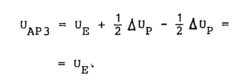
Dabei ist von großem Vorteil, daß in allen drei Schaltzustands-Kombinationen die Verluste, die in den Stelleinheiten auftreten, extrem gering sind. Insbesondere erfolgt auch die unveränderte Weitergabe der Eingangsspannung auf den Ausgang des Stelleinheiten-Paares in der dritten Schaltzustands-Kombination praktisch verlustfrei. Ein solches Stelleinheiten-Paar besitzt den Vorteil, daß von jeder einzelnen Stelleinheit nur die Hälfte der für die betreffende Stufe vorgesehenen Spannungs- bzw. Leistungsänderung aufgebracht werden muß. Es werden zwar zwei Transformatoren benötigt, doch können diese der halben Leistung entsprechend auch erheblich kleiner und leichter dimensioniert werden. Dies ist insbesondere bei der Herstellung, dem Transport sowie bei der Ersatzteilhaltung von Vorteil.It is of great advantage that the losses that occur in the control units are extremely low in all three switching state combinations. In particular, the unchanged transmission of the input voltage to the output of the pair of actuators in the third switching state combination is practically loss-free. Such a pair of actuating units has the advantage that only half of that for each individual actuating unit is for the respective one The intended voltage or power change must be applied. Although two transformers are required, they can also be dimensioned considerably smaller and lighter in accordance with half the power. This is particularly advantageous when it comes to manufacturing, transport and spare parts storage.
Im allgemeinen bleibt für ein Stelleinheiten-Paar die vierte Schaltzustands-Kombination ungenutzt, bei der sich die erste Stelleinheit im zweiten Schaltzustand und die zweite Stelleinheit im ersten Schaltzustand befindet. Dies läßt sich in folgender Tabelle 1 zusammenfassen:

Grundsätzlich ist es hier nicht erforderlich, daß jede der beiden Stelleinheiten des Stelleinheiten-Paares für sich allein in den dritten Schaltzustand gebracht werden kann.Basically, it is not necessary here that each of the two actuating units of the pair of actuating units can be brought into the third switching state on its own.
Vorzugsweise wird jedoch auch bei einem Stelleinheiten-Paar jede der beiden Stelleinheiten gemäß einer der oben beschriebenen Ausführungsformen so ausgebildet, daß sie für sich allein in den dritten Schaltzustand gebracht werden kann; sieht man dabei in jeder Stelleinheit die oben erwähnte Strombegrenzungsschaltung bzw. Strombegrenzungsschaltungen vor, so läßt sich mit Hilfe von V-MOS-Transistor-Schaltern ein außerordentlich schnelles, in mehreren Teilschritten erfolgendes Umschalten von jeder Schaltzustands-Kombination des Stelleinheiten-Paares in jede andere Schaltzustands-Kombination durchführen.Preferably, however, in the case of a pair of actuating units, each of the two actuating units is designed in accordance with one of the above-described embodiments such that it can be brought into the third switching state on its own; you can see the above in every control unit mentioned current limiting circuit or current limiting circuits before, with the help of V-MOS transistor switches an extremely fast, in several steps switching from each switching state combination of the actuator pair in any other switching state combination can be carried out.
Soll z.B. das Stelleinheiten-Paar aus der zweiten Schaltzustands-Kombination ![]()
![]()
![]()
![]()
![]()
![]()
Entsprechendes gilt für einen Übergang des Stelleinheiten-Paares aus der ersten Schaltzustands-Kombination ![]()
![]()
Allerdings ist es zweckmäßig, das Stelleinheiten-Paar dann, wenn die Ausgangsspannung UAP längere Zeit gleich der Eingangsspannung UEP bleiben soll, aus dieser weiteren Schaltzustands-Kombination in die oben beschriebene dritte Schaltzustands-Kombination umzuschalten. Dies erfolgt zu den jeweils günstigen Zeitpunkten dadurch, daß durch das Öffnen der entsprechenden Schalter die erste Stelleinheit in ihren ersten Schaltzustand und die zweite Stelleinheit in ihren zweiten Schaltzustand gebracht wird. Der Ausgangsspannung des Stelleinheiten-Paares geht dabei von ![]()
![]()
![]()
![]()
Die dritte Schaltzustands-Kombination hat gegenüber der weiteren Schaltzustands-Kombination den Vorteil, daß aus ihr heraus erforderlichenfalls ein Übergang in die erste oder die zweite Schaltzustands-Kombination in zwei gleich großen Änderungsschritten erfolgen kann, von denen der erste ohne jede Verzögerung dadurch durchführbar ist, daß durch Schließen des betreffenden Schalters die zweite oder die erste Stelleinheit in ihren dritten Schaltzustand gebracht wird. Dadurch geht die Ausgangsspannung des Stelleinheiten-Paares augenblicklich von ![]()
![]()
![]()
![]()
![]()
![]()
![]()
![]()
![]()
![]()
Der Übergang von der ersten in die zweite oder von der zweiten in die erste Schaltzustands-Kombination erfolgt ebenfalls in zwei Schritten, von denen der erste sofort und der zweite spätestens innerhalb der nächsten Halbperiode der Wechselspannung durchgeführt werden kann. In diesem Fall besteht der erste Schritt darin, daß beide Stelleinheiten gleichzeitig durch Schließen der entsprechenden Schalter in ihren dritten Schaltzustand gebracht werden; im zweiten Schritt werden dann die beiden Stelleinheiten durch Öffnen der entsprechenden Schalter jeweils in ihren zweiten bzw. ihren ersten Schaltzustand übergeführt.The transition from the first to the second or from the second to the first switching state combination likewise takes place in two steps, of which the first can be carried out immediately and the second at the latest within the next half cycle of the AC voltage. In this case, the first step consists in bringing both actuating units into their third switching state simultaneously by closing the corresponding switches; in the second step, the two actuating units are each converted into their second or their first switching state by opening the corresponding switches.
Wird eine aus einem oder mehreren solcher Stelleinheiten-Paare (die dann unterschiedliche Spannungsänderungen bewirken können) bestehende Transformator-Schaltung als Spannungsregler oder Spannungskonstanter eingesetzt, so lassen sich mit ihr auch die extrem hohen Anforderungen hinsichtlich der Schaltgeschwindigkeit und Schaltgenauigkeit erfüllen, wie sie beispielsweise bei der Stromversorgung von Datenverarbeitungsanlagen gestellt werden.If a transformer circuit consisting of one or more such pairs of actuating units (which can then cause different voltage changes) is used as a voltage regulator or voltage constant, it can also be used to meet the extremely high requirements in terms of switching speed and switching accuracy, such as those used in the Power supply of data processing systems are provided.
Um einen größeren Bereich von Ausgangsspannungswerten in kleinen Spannungsschritten Überdecken zu können, ist es vorteilhaft, mehrere Stufen, die entweder aus einzelnen Stelleinheiten die jeweils für sich in den dritten Schaltzustand gebracht werden können oder aus den oben beschriebenen Stelleinheiten-Paaren bestehen (wobei in einer Anordnung auch beide Arten gemischt werden können), seriell hintereinander zu schalten und die Spannungsdifferenzen ± ΔU₁, ...,± ΔUn, die n solcher Stufen erzeugen können, voneinander verschieden zu wählen. Besonders vorteilhaft ist es, wenn die Prozentwerte, die sich ergeben, wenn man jede dieser Spannungsdifferenzen durch die durch 100 geteilte Versorgungsspannung dividiert, zueinander im Verhältnis ganzzahliger Dreierpotenzen stehen. Gilt also für die kleinste, durch eine der Stufen erzeugbare Spannungsdifferenz ± ΔUmin: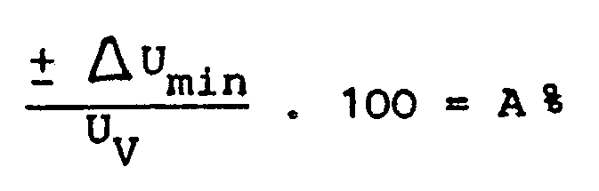
so werden die Spannungsdifferenzen der anderen Stufen so gewählt, daß sie in etwa gleich ± 3A%, ± 9A% usw. der Versorgungsspannung UV sind.In order to be able to cover a larger range of output voltage values in small voltage steps, it is advantageous to have several stages, which either consist of individual actuating units, each of which can be brought into the third switching state, or consist of the actuating unit pairs described above (in one arrangement also both types can be mixed), to connect in series and to select the voltage differences ± ΔU₁, ..., ± ΔU n , which can generate n such stages, from each other. It is particularly advantageous if the percentage values that result when each of these voltage differences is divided by the supply voltage divided by 100 are in relation to one another in the form of integer powers of three. This applies to the smallest voltage difference ± ΔU min that can be generated by one of the stages:
so the voltage differences of the other stages are chosen so that they are approximately equal to ± 3A%, ± 9A% etc. of the supply voltage U V.
Sind beispielsweise in einer Transformatorschaltung drei Stufen hintereinander geschaltet, und werden für jede Stufe die drei oben genannten Schaltzustände bzw. Schaltzustands-Kombinationen verwendet, so sind für die gesamte Transformatorschaltung siebenundzwanzig Kombinationen von Schaltzuständen möglich, von denen eine die von der Spannungsquelle abgegebene Versorgungsspannung mit nahezu unveränderter Amplitude an die Last gelangen läßt, während dreizehn Kombinationen die Amplitude der Versorgungsspannung in etwa um ganzzahlige Vielfache von A% erhöhen und dreizehn Kombinationen diese Amplitude in etwa um ganzzahlige Vielfache von A% erniedrigen. Dies ist in Tabelle 2 genauer dargestellt.If, for example, three stages are connected in series in a transformer circuit, and if the three switching states or switching state combinations mentioned above are used for each stage, twenty-seven combinations of switching states are possible for the entire transformer circuit, one of which with almost the supply voltage supplied by the voltage source unchanged amplitude can get to the load, while thirteen combinations increase the amplitude of the supply voltage by approximately integer multiples of A% and thirteen combinations decrease this amplitude by approximately integer multiples of A%. This is shown in more detail in Table 2.
In dieser Tabelle ist in der linken Spalte die laufende Nummer n der jeweiligen Kombination von Schaltzuständen wiedergegeben, wobei durch das hochgestellte Vorzeichen "+" oder "-" angedeutet wird, ob es sich um eine Kombination handelt, die zu einer Vergrößerung ("+") der Amplitude der Versorgungsspannung führt oder um eine Kombination, die die Versorgungsspannung erniedrigt ("-").
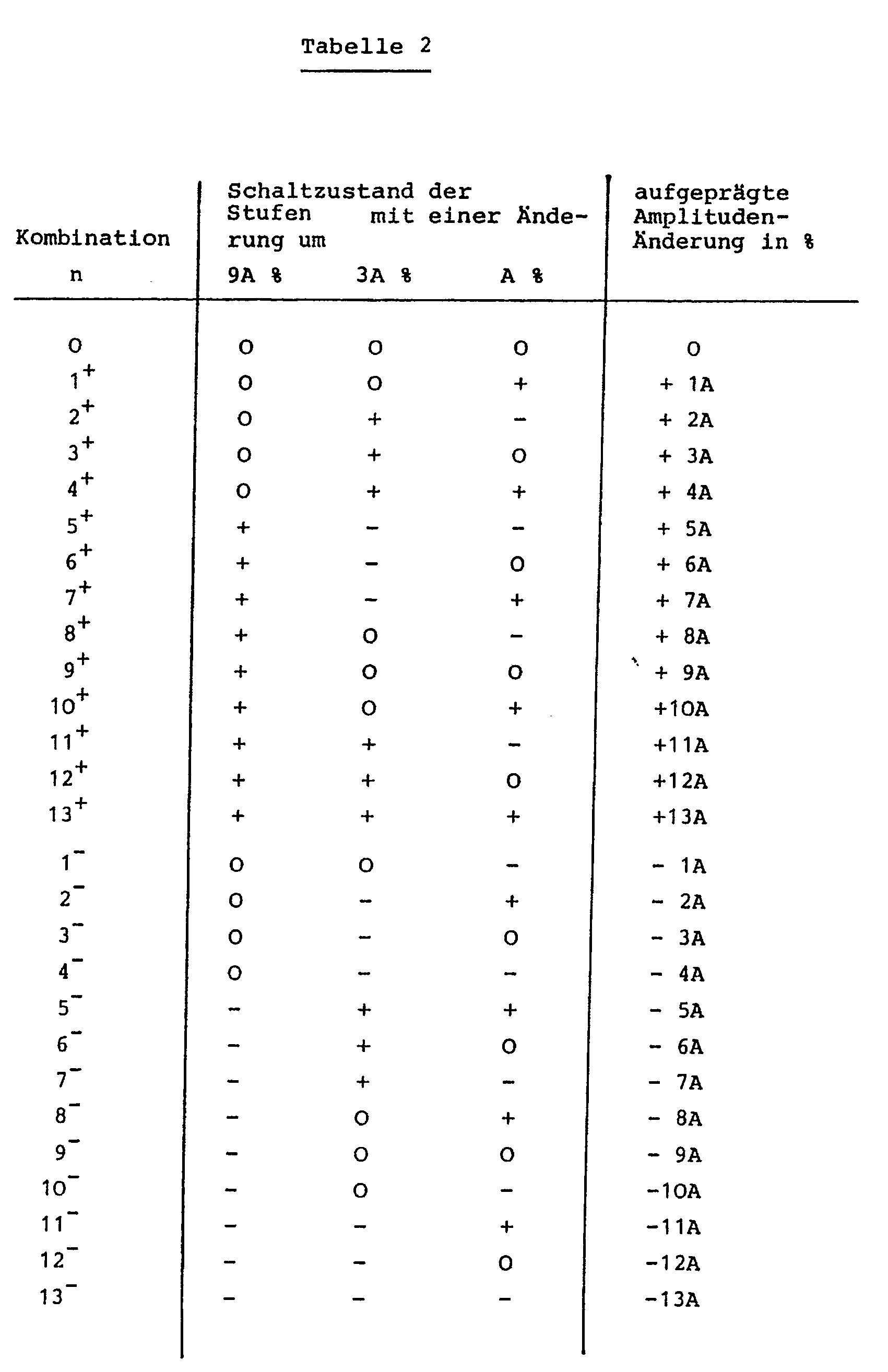
In der mittleren Spalte bedeutet ein "+", daß sich in der betreffenden Stufe die eine Stelleinheit bzw. beide Stelleinheiten eines Paares im ersten Schaltzustand befinden, so daß die Amplitude der Versorgungsspannung um 9A%, 3A% oder A% vergrößert wird, während ein "-" eine entsprechende Verkleinerung bedeutet und "O" den dritten Schaltzustand einer einzelnen Stelleinheit bzw. die Schaltzustands-Kombination 3 (siehe Tabelle 1) des betreffenden Stelleinheiten-Paares symbolisiert, in dem bzw. in der die Amplitude der Eingangs-Wechselspannung unverändert weitergegeben wird. In der rechten Spalte sind die durch die jeweilige Kombination der Schaltzustände aller Stufen erzielbaren Gesamtänderungen der Amplitude wiedergegeben. Dabei sind nur gerundete Werte angegeben, die nicht berücksichtigen, daß sich die Eingangsspannung der näher bei der Last angeordneten Stufen in Abhängigkeit vom Schaltzustand der vorausgehenden Stufen ändern kann.In the middle column, a "+" means that one or both actuating units of a pair are in the first switching state in the relevant stage, so that the amplitude of the supply voltage is increased by 9A%, 3A% or A% while a "-" means a corresponding reduction and "O" symbolizes the third switching state of an individual control unit or the switching state combination 3 (see Table 1) of the relevant control unit pair, in which or in which the amplitude of the input AC voltage is passed on unchanged becomes. The right column shows the total changes in amplitude that can be achieved by the respective combination of the switching states of all stages. Only rounded values are given, which do not take into account that the input voltage of the stages closer to the load can change depending on the switching state of the preceding stages.
Man sieht, daß die Amplitudenänderung mit Hilfe einer solchen erfindungsgemäßen Transformatorschaltung in diskreten Schritten erfolgt, wobei die Schrittweite von einer Schaltzustands-Kombination zur nächstn immer in etwa gleich A% der jeweiligen Versorgungsspannung ist.It can be seen that the amplitude change takes place with the aid of such a transformer circuit according to the invention in discrete steps, the step width from one switching state combination to the next always being approximately equal to A% of the respective supply voltage.
Ist eine Stufe aus zwei Stelleinheiten aufgebaut, die ein Paar bilden, so können alternativ zu der eben erläuterten Anordnung auch von jedem Stelleinheiten-Paar nur zwei Schaltzustands-Kombinationen Verwendung finden, beispielsweise die Schaltzustands-Kombination O, in der die Ausgangsspannung gleich der Eingangsspannung ist, und die Kombination "-", in der die Ausgangsspannung um n·A% niedriger als die Eingangsspannung ist, wobei n für jedes Stelleinheiten-Paar einen anderen ganzzahligen Wert annimmt. Für diesen Verwendungsfall ist es möglich, die Stelleinheiten-Paare so zu konstruieren, daß sie nur diese beiden Schaltzustands-Kombinationen einnehmen können. Dies kann in der Weise geschehen, daß z.B. die vordere Stelleinheit eines jeden Paares eine fest verdrahtete, nicht schaltbare weitere Wicklung aufweist, die permanent beispielsweise eine negativ aufgeprägte Spannung - (n/2)·A% induziert, während die zweite Stelleinheit eine addierende und eine subtrahierende weitere Wicklung besitzt, die alternativ so geschaltet werden können, daß sie entweder eine Spannung von + (n/2)·A% oder von - (n/2)·A% induzieren, was in Verbindung mit der induzierten Spannung - (n/2)·A% der vorderen Stelleinheit entweder eine Spannungsänderung O oder - n·A% ergibt. Entsprechend können auch Stelleinheiten-Paare vorgesehen werden, die nur die beiden Schaltzustands-Kombinationen O und + n·A% annehmen können.If a stage is made up of two actuating units which form a pair, then, as an alternative to the arrangement just explained, only two switching state combinations can be used for each pair of actuating units Use is made, for example, of the switching state combination O, in which the output voltage is equal to the input voltage, and the combination “-”, in which the output voltage is lower than the input voltage by n · A%, where n is different for each pair of actuating units takes an integer value. For this application, it is possible to construct the pairs of actuators so that they can only assume these two switching state combinations. This can be done in such a way that, for example, the front actuating unit of each pair has a hard-wired, non-switchable further winding that permanently induces, for example, a negatively impressed voltage - (n / 2) · A%, while the second actuating unit has an adding and has a subtracting further winding, which can alternatively be switched such that they either induce a voltage of + (n / 2) · A% or of - (n / 2) · A%, which in connection with the induced voltage - ( n / 2) · A% of the front actuator either results in a voltage change O or - n · A%. Correspondingly, control unit pairs can also be provided, which can only assume the two switching state combinations O and + n · A%.
In allen diesen Fällen erfolgt die Änderung der Ausgangsspannung der gesamten Transformatorschaltung gegenüber der Eingangsspannung nicht nach dem in Tabelle 2 wiedergegebenen Ternär-Kode sondern nach einem Binär-Kode. Zwar werden hier zur Überdeckung desselben Spannungsänderungsbereiches mehr Stelleinheiten-Paare als beim Ternär-Kode benötigt; es gibt jedoch Anwendungsfälle, in denen ohnehin die Eingangsspannung ausgehend von einer Gesamtänderung O nur in einer Richtung verändert werden soll und/oder der Spannungsänderungsbereich nicht groß ist. Dann kann der Vorteil einer rein binären Ansteuerung den erhöhten Bedarf an Stelleinheiten unter Umständen überwiegen.In all these cases, the change in the output voltage of the entire transformer circuit with respect to the input voltage does not take place according to the ternary code shown in Table 2, but according to a binary code. To cover the same voltage change range, more actuator pairs are required than with the ternary code; However, there are applications in which the input voltage is to be changed in only one direction based on an overall change O and / or the voltage change range is not large. Then he can The advantage of a purely binary control may outweigh the increased need for control units.
Unabhängig davon, wieviele Stufen hintereinander geschaltet werden und ob ein Binär- oder ein Ternär- oder ein anderer Kode Verwendung findet, ist es ein hervorstechendes Merkmal einer derart aufgebauten erfindungsgemäßen Transformatorschaltung, daß sie eine stufenweise bzw. digitale Beeinflussung auch von sehr großen Leistungen erlaubt. Im Gegensatz zu analog arbeitenden Systemen besitzt sie eine außerordentlich hohe Regel- bzw. Steuerungsgeschwindigkeit. Die jeweils erzielte Genauigkeit hängt dabei im wesentlichen nur von der Zahl der verwendeten Stelleinheiten bzw. Stufen ab.Regardless of how many stages are connected in series and whether a binary or a ternary or another code is used, it is a salient feature of a transformer circuit according to the invention which is constructed in such a way that it allows a gradual or digital influencing even of very large powers. In contrast to analog systems, it has an extraordinarily high regulating or control speed. The accuracy achieved in each case essentially depends only on the number of actuating units or stages used.
Der typische und bevorzugte Anwendungsfall einer aus zwei, drei oder mehr Stufen bestehenden erfindungsgemäßen Transformatorschaltung besteht jedoch nicht darin, daß ausgehend von einer festen, von einer Spannungsquelle stammenden Versorgungsspannung neun, siebenundzwanzig oder mehr Ausgangsspannungen nacheinander wahlweise erzeugbar sein sollen.However, the typical and preferred application of a transformer circuit according to the invention consisting of two, three or more stages does not consist in the fact that nine, twenty-seven or more output voltages should be able to be generated one after the other starting from a fixed supply voltage originating from a voltage source.
Vielmehr ist in einem besonders bevorzugten Anwendungsfall der Einsatz einer solchen Transformatorschaltung als Spannungskonstanter und/oder Spannungsregler vorgesehen. Das bedeutet, daß als Sollwert SL für die der Last zugeführte Spannung entweder der Nennwert der von der Spannungsquelle abgegebenen Versorgungsspannung UV oder ein anderer Spannungswert gewählt werden können. Allerdings muß ein solcher anderer Sollwert innerhalb des Änderungsbereichs der erfindungsgemäßen Transformatorschaltung liegen. Liegt er sehr nahe an der Grenze dieses Änderungsbereiches, so ist eine Regelung der Lastspannung UL nur bei Abweichungen vom Sollwert SL in einer Richtung möglich. Dies ist aber in Fällen, in denen Abweichungen in der anderen Richtung nicht auftreten, völlig ausreichend.Rather, the use of such a transformer circuit as a voltage constant and / or voltage regulator is provided in a particularly preferred application. This means that either the nominal value of the supply voltage U V emitted by the voltage source or another voltage value can be selected as the target value S L for the voltage supplied to the load. However, such a different setpoint must lie within the change range of the transformer circuit according to the invention. If it is very close to the limit of this change range, the load voltage U L can only be regulated in one direction if there are deviations from the set value S L possible. However, this is completely sufficient in cases where deviations in the other direction do not occur.
Im folgenden wird die Anwendung als symmetrischer Spannungsregler genauer erläutert, mit dessen Hilfe verhindert wird, daß die Amplitude der einer Last zugeführten Lastspannung von einem vorgegebenen Sollwert SL um mehr als ± δ % abweicht, der gleich dem Nennwert der Versorgungsspannung UV ist, die in einem wesentlich größeren Bereich, beispielsweise um maximal ± Δ % des Nennwertes schwanken kann.In the following, the application as a symmetrical voltage regulator is explained in more detail, with the aid of which the amplitude of the load voltage supplied to a load is prevented from deviating from a predetermined desired value S L by more than ± δ%, which is equal to the nominal value of the supply voltage U V , which can fluctuate in a much larger range, for example by a maximum of ± Δ% of the nominal value.
Zu diesem Zweck umfaßt eine erfindungsgemäße Schaltungsanordnung neben einer Transformatorschaltung mit entsprechend vielen Stufen eine Meßfühleranordnung, die die Amplitude der versorgungsspannung und/oder die Amplitude der Lastspannung mißt, eine Komparatoranordnung, die das oder die Meßfühlersignale mit einem oder mehreren Referenzwerten vergleicht und bei Abweichungen entsprechende Differenzsignale erzeugt, sowie eine Schaltersteuerung, die diese Differenzsignale beispielsweise mit einer fest einprogrammierten Tabelle von Differenzsignalwerten vergleicht. Aus diesem Vergleich ermittelt die Schaltersteuerung diejenige Kombination n⁺ oder n⁻ von Schaltzuständen (siehe Tabelle 2), die für eine Kompensation der aufgetretenen Abweichung der Versorgungsspannung vom Nennwert erforderlich ist, so daß die Lastspannung innerhalb des vorgegebenen Bereiches SL± δ % bleibt.For this purpose, a circuit arrangement according to the invention comprises, in addition to a transformer circuit with a corresponding number of stages, a sensor arrangement which measures the amplitude of the supply voltage and / or the amplitude of the load voltage, a comparator arrangement which compares the sensor signal or signals with one or more reference values and, in the event of deviations, corresponding difference signals generates, as well as a switch control that compares these difference signals, for example, with a permanently programmed table of difference signal values. From this comparison, the switch controller determines the combination n⁺ or n⁻ of switching states (see Table 2) that is required to compensate for the deviation of the supply voltage from the nominal value, so that the load voltage remains within the specified range S L ± δ%.
Es sei nun angenommen, daß die Amplitude der Versorgungsspannung zunächst dem Nennwert und damit auch dem Sollwert SL entspricht, dann aber im Laufe der Zeit von diesem Nennwert in zunehmendem Maße beispielsweise nach oben abweicht: In diesem Fall muß die Schaltersteuerung von der zunächst vorhandenen Schaltzustands-Kombination n = O (siehe Tabelle 2), bei der die Lastspannung UL gleich der Versorgungsspannung UV ist, rechtzeitig zur Schaltzustands-Kombination n = 1⁻, bei weiterem Ansteigen zur Kombination n = 2⁻ usw. übergehen. Dadurch wird ein entsprechendes ganzzahliges Vielfaches von A % von der Versorgungsspannung subtrahiert und somit die Lastspannung im gewünschten Bereich SL± δ % gehalten.It is now assumed that the amplitude of the supply voltage initially corresponds to the nominal value and thus also to the nominal value S L , but then increases over time from this nominal value Dimensions deviate upwards, for example: In this case, the switch control must be in time for the switching state combination n = O (see table 2), in which the load voltage U L is equal to the supply voltage U V , in time for the switching state combination n = 1⁻ , continue to increase to the combination n = 2⁻ etc. As a result, a corresponding integer multiple of A% is subtracted from the supply voltage and the load voltage is thus kept in the desired range S L ± δ%.
Bei stetig zunehmender positiver Abweichung erfolgt der Übergang von der n⁻-ten Kombination zur (n+1)⁻-ten Kombination jeweils bei einer bestimmten Schaltschwelle SWn-/(n+1)-, d.h. einem festgelegten Amplitudenwert der Versorgungsspannung. Nimmt die positive Abweichung wieder stetig ab, so erfolgt in etwa bei derselben Schaltschwelle in umgekehrter Richtung der Übergang von der (n+1)⁻-ten Kombination zur n⁻-ten Kombination von Schaltzuständen. Es ist vorteilhaft, die beiden zuletzt genannten Schaltschwellen durch eine kleine Spannungsdifferenz voneinander zu trennen. Durch die so erzielte "Hysterese" wird ein zu häufiges Schaltspiel in den Fällen verhindert, in denen die Versorgungsspannung UV längere Zeit einen Wert besitzt, der gleich einer Schaltschwelle ist, und um diesen Wert geringfügig schwankt.With a continuously increasing positive deviation, the transition from the nth combination to the (n + 1) ⁻th combination takes place at a certain switching threshold SW n - / (n + 1) - ie a fixed amplitude value of the supply voltage. If the positive deviation continues to decrease, the transition from the (n + 1) ⁻th combination to the n⁻th combination of switching states takes place in the opposite direction at approximately the same switching threshold. It is advantageous to separate the last two switching thresholds from one another by means of a small voltage difference. The "hysteresis" achieved in this way prevents an excessive switching cycle in cases in which the supply voltage U V has a value for a long time which is equal to a switching threshold and fluctuates slightly around this value.
Entsprechendes gilt auch für negative Abweichungen der Amplitude der Versorgungsspannung vom Nennwert nur daß hier die Schaltschwellen mit SWn+/(n+1)+ bezeichnet werden, weil in diesem Fall bei zunehmender Abweichung nach unten von der additiven Aufprägung des n-fachen der minimalen Amplitudenänderung A % zur additiven Aufprägung des (n+1)-fachen von A % übergegangen werden muß, um die gewünschte Konstanz der Amplitude der Lastspannung zu erzielen.The same applies to negative deviations in the amplitude of the supply voltage from the nominal value only that the switching thresholds are denoted by SW n + / (n + 1) +, because in this case with increasing deviations downwards from the additive imprint of n times the minimum Amplitude change A% to additive impressions of (n + 1) times from A% must be achieved in order to achieve the desired constancy of the amplitude of the load voltage.
Bei jedem Übergang von einer Kombination von Schaltzuständen zu einer benachbarten Kombination ändert sich die Ampliutude der Lastspannung sprungartig etwa um A %. Vorzugsweise werden die Schaltschwellen so festgelegt, daß dann, wenn die Amplitude der Versorgungsspannung den Wert der betreffenden Schaltschwelle ohne sprungartige Änderung durchläuft, die Amplitudenwerte ULvor und ULnach symmetrisch zum Sollwert liegen. Dabei ist ULvor die Amplitude der Lastspannung vor dem Umschaltvorgang und ULnach die Amplitude der Lastspannung nach dem Umschaltvorgang. Es soll also mit möglichst guter Näherung gelten:
![]()
weiterhin gilt
Der Prozentwert A ist zwar konstant, ist aber nicht auf den Sollwert SLsondern auf die Amplitude der Eingangsspannung der jeweiligen Stufe bezogen. Somit ist die Größe von ULvor und ULnach davon abhängig, von welcher Kombination von Schaltzuständen ein Übergang zu einer benachbarten Kombination erfolgt.With each transition from a combination of switching states to an adjacent combination, the amplitude of the load voltage changes abruptly by approximately A%. The switching thresholds are preferably set such that when the amplitude of the supply voltage passes the value of the switching threshold in question without a sudden change, the amplitude values U Lvor and U Lnach are symmetrical to the setpoint. U Lvor is the amplitude of the load voltage before the switching process and U Lnach is the amplitude of the load voltage after the switching process. The following should therefore apply with the best possible approximation:
![]()
still applies
The percentage value A is constant, but is not related to the target value S L but to the amplitude of the input voltage of the respective stage. The size of U Lvor and U Lnach therefore depends on which combination of switching states a transition to an adjacent combination takes place.
Die obige Gleichtung kann durch geeignete Wahl der Schaltschwellen SW in jedem Fall eingehalten werden. Auch ist es erfindungsgemäß möglich, durch eine entsprechende Wahl von A sicherzustellen, daß ULvor und ULnach innerhalb des durch die gewünschte Regelgenauigkeit SL± δ % vorgegebenen Amplitudenbereiches liegen, wobei der Prozentwert auf den Sollwert SL= 100 % bezogen ist.The above equation can be maintained in any case by suitable selection of the switching thresholds SW. It is also possible according to the invention to ensure by a corresponding selection of A that U Lvor and U Lnach lie within the amplitude range specified by the desired control accuracy S L ± δ%, the percentage value being related to the target value S L = 100%.
Bei der Festlegung des Wertes von A ist zu berücksichtigen, daß einerseits A möglichst groß sein sollte, damit möglichst wenig Stelleinheiten zur Abdeckung eines gegebenen Schwankungsbereiches Δ erforderlich sind, daß aber andererseits A nicht zu groß gewählt werden darf, weil sonst die gewünschte Regelgenauigkeit δ nicht eingehalten werden kann. Erfindungsgemäß wird A vorzugsweise so gewählt, daß es zwischen 1,6 · δ und 1,8 · δ liegt.When determining the value of A, it must be taken into account that on the one hand A should be as large as possible so that as few actuators as possible are required to cover a given fluctuation range Δ, but on the other hand A should not be chosen too large, because otherwise the desired control accuracy δ will not can be observed. According to the invention, A is preferably chosen so that it is between 1.6 · δ and 1.8 · δ.
Es sei hier nochmals darauf hingewiesen, daß die Schaltschwellen unabhängig davon verwendet werden können, ob die Schaltungsanordnung als Spannungskonstanter oder als Spannungsregler arbeitet, ob also die Lastspannung UL auf einem Sollwert SL gehalten wird, der gleich dem Nennwert der von der Spannungsquelle abgegebenen Versorgungsspannung ist, oder auf einem Sollwert, der sich von diesem Nennwert unterscheidet.It should be pointed out again here that the switching thresholds can be used regardless of whether the circuit arrangement works as a voltage constant or as a voltage regulator, i.e. whether the load voltage U L is kept at a setpoint value S L which is equal to the nominal value of the supply voltage emitted by the voltage source or at a target value that differs from this nominal value.
Auch ist die Verwendung dieser Schaltschwellen unabhängig davon, ob mit der Meßfühleranordnung die Versorgungsspannung oder die Lastspannung gemessen wird. Im ersten Fall kann die Differenz der obigen Schaltschwellen zum Sollwert SLunmittelbar in der von der Schaltersteuerung benutzten Tabelle enthalten sein, mit welcher das vom Komparator gelieferte Differenzsignal verglichen wird. Im zweiten Fall muß die Schaltersteuerung aus der Annäherung der Amplitude der Lastspannung an einen der Werte ULvor und ULnach und/oder der Kenntnis der momentan gültigen Kombination von Schaltzuständen ermitteln, an welche Schaltschwelle sich-die Versorgungsspannung gerade annähert und welche Umschaltung daher vorgenommen werden muß.The use of these switching thresholds is also independent of whether the supply voltage or the load voltage is measured with the sensor arrangement. In the first case, the difference between the above switching thresholds and the desired value S L can be contained directly in the table used by the switch control, with which the difference signal supplied by the comparator is compared. In the second case, the switch control must determine from the approximation of the amplitude of the load voltage to one of the values U Lvor and U Lnach and / or knowledge of the currently valid combination of switching states, to which switching threshold the supply voltage is approaching and which switchover is therefore undertaken got to.
Eine weitere Möglichkeit besteht darin, daß die Meßfühleranordnung die Amplitude der Wechselspannungen vor und hinter der Transformatorschaltung mißt. Es werden dann also die Änderungen sowohl der Versorgungsspannung UV als auch der Lastspannung UL erfaßt und so ausgewertet, daß die Schalter der Stelleinheiten so gesteuert werden, daß sich eine möglichst gute Konstanz der Amplitude der der Last zugeführten Spannung ergibt.Another possibility is that the sensor arrangement measures the amplitude of the alternating voltages in front of and behind the transformer circuit. The changes in both the supply voltage U V and the load voltage U L are then detected and evaluated in such a way that the switches of the actuating units are controlled in such a way that the amplitude of the voltage supplied to the load is as constant as possible.
Vorteilhafterweise kann eine erfindungsgemäße Transformatorschaltung bei Mehrphasensystemen mit oder ohne Null-Leiter eingesetzt werden. Im ersten Fall ist für jede Phase wenigstens eine Stelleinheit vorgesehen, deren erste Wicklung jeweils so in dem betreffenden Phasenleiter liegt, daß sie von dem auf diesem Phasenleiter fließenden Laststrom durchflossen wird, während der Anschluß-Verbindungsleiter einer jeden Stelleinheit mit dem Null-Leiter des Mehrphasensystems verbunden ist.A transformer circuit according to the invention can advantageously be used in multiphase systems with or without a neutral conductor. In the first case, at least one control unit is provided for each phase, the first winding of which lies in the respective phase conductor in such a way that the load current flowing on this phase conductor flows through it, while the connecting connecting conductor of each control unit with the neutral conductor of the multiphase system connected is.
Weist das Mehrphasensystem keinen von der Spannungsquelle zum Verbrauch führenden Null-Leiter auf, so werden die ersten Wicklungen der Stelleinheiten, die für eine bestimmte Phase vorgesehen sind, wieder in den Phasenleiter geschaltet und es werden sämtliche Anschluß-Verbindungsleiter miteinander verbunden, wodurch ein künstlicher Null-Leiter gebildet wird, der auf einem beliebigen Potential liegen kann.If the multiphase system does not have a neutral conductor leading from the voltage source to consumption, the first windings of the actuating units which are provided for a specific phase are switched back into the phase conductor and all the connecting connecting conductors are connected to one another, thereby creating an artificial zero -Conductor is formed, which can be at any potential.
Schließlich können bei einem Mehrphasensystem ohne Nulleiter die für die verschiedenen Phasen vorgesehenen Stelleinheiten in einer verketteten Schaltung angeordnet werden.Finally, in the case of a multi-phase system without a neutral conductor, the actuating units provided for the different phases can be arranged in a daisy-chained circuit.
Die Erfindung wird im folgenden anhand von Ausführungsbeispielen unter Bezugnahme auf die Zeichnung beschrieben; in dieser zeigt:
- Fig. 1
- eine Transformatorschaltung, bei der zwischen Spannungsquelle und Last eine Stelleinheit angeordnet ist, die gemäß einer ersten Ausführungsform einen Transformator mit einer einzigen weiteren Wicklung besitzt, die zur ersten Wicklung parallelgeschaltet werden kann,
- Fig. 2
- eine Transformatorschaltung, bei der zwischen Spannungsquelle und Last eine Stelleinheit angeordnet ist, die gemäß einer zweiten Ausführungsform einen Transformator mit zwei weiteren Wicklungen besitzt, die miteinander in Reihe zur ersten Wicklung parallelgeschaltet werden können,
- Fig. 3
- den Aufbau einer Strombegrenzungsschaltung, wie sie bei den in den Fig. 1 und 2 wiedergegebenen Stelleinheiten Verwendung findet,
- Fig. 4
- ein Diagramm zur Erläuterung der Wahl der günstigsten Schaltzeitpunkte beim Übergang von einem Schaltzustand in einen anderen,
- Fig. 5
- eine als einphasiger Spannungskonstanter aufgebaute Transformatorschaltung mit drei in Reihe geschalteten Stufen, und
- Fig. 6
- eine weitere Ausführungsform eines Spannungskonstanters für ein 3-Phasen-System.
- Fig. 1
- a transformer circuit in which a control unit is arranged between the voltage source and the load, which according to a first embodiment has a transformer with a single further winding which can be connected in parallel with the first winding,
- Fig. 2
- a transformer circuit in which a control unit is arranged between the voltage source and the load, which according to a second embodiment has a transformer with two further windings which can be connected in parallel with one another in series with the first winding,
- Fig. 3
- the construction of a current limiting circuit, as used in the control units shown in FIGS. 1 and 2,
- Fig. 4
- 1 shows a diagram to explain the selection of the cheapest switching times when changing from one switching state to another,
- Fig. 5
- a transformer circuit constructed as a single-phase voltage constant with three stages connected in series, and
- Fig. 6
- a further embodiment of a voltage constant for a 3-phase system.
Fig. 1 zeigt eine Wechselspannungsquelle 1, die eine Versorgungsspannung UV abgibt, die den Eingangsanschlüssen 2, 3 einer Stelleinheit 4 als Eingangsspannung UE zugeführt wird. An den Ausgangsanschlüssen 5,6 der Stelleinheit 4 erscheint eine Ausgangsspannung UA, die einer Last 7 als Lastspannung UL zugeführt wird.1 shows an
Mit Hilfe der Stelleinheit 4 ist die Amplitude der Ausgangsspannung UA gegenüber der Amplitude der Eingangsspannung UE veränderbar. Zu diesem Zweck umfaßt die Stelleinheit 4 einen Transformator 8, dessen erste Wicklung 9 zwischen den Eingangsanschluß 2 und den Ausgangsanschluß 5 geschaltet ist, während der Eingangsanschluß 3 mit dem Ausgangsanschluß 6 vermittels des Anschluß-Verbindungsleiters 10 direkt galvanisch leitend verbunden ist. Auf diese Weise ist von der Spannungsquelle 1 her gesehen die erste Wicklung 9 mit der Last 7 in Reihe geschaltet.With the help of the
Der Transformator 8 besitzt eine weitere Wicklung 11, die über den Eisenkern 12 des Transformators 8 mit dessen erster Wicklung 9 magnetisch gekoppelt ist. Mit den beiden Enden 13, 14 der weiteren Wicklung 11 sind jeweils zwei Schalter 150, 152 bzw. 151, 153 verbunden.The
Ist der Schalter 150 geschlossen, so verbindet er das Ende 13 der weiteren Wicklung 11 mit dem Eingangsanschluß 2, mit dem auch das eine Ende der ersten Wicklung 9 verbunden ist. Ist der Schalter 151 geschlossen, so verbindet er das andere Ende 14 der weiteren Wicklung 11 mit dem Ausgangsanschluß 5, mit dem das andere Ende der ersten Wicklung 9 verbunden ist.If the
Ist der Schalter 152 geschlossen, so verbindet er das Ende 13 der weiteren Wicklung 11 mit einer Leitung 155, mit der der Schalter 153 im geschlossenen Zustand auch das andere Ende 14 der weiteren Wicklung 11 verbindet. Zwischen der Leitung 155 und dem Anschluß-Verbindungsleiter 10 ist eine Schaltungsanordnung 157 vorgesehen, die ein einfacher steuerbarer Aus/Ein-Schalter sein kann, vorzugsweise aber von einer Strombegrenzungsschaltung gebildet wird, wie sie weiter unten unter Bezugnahme auf Fig. 3 noch genauer erläutert wird.If the
Mit Hilfe der Schalter 150 bis 153 kann die Stelleinheit 4 in vier verschiedene Schaltzustände gebracht werden. Im ersten Schaltzustand, in dem die Schalter 150 und 153 geschlossen sind, wird an die weitere Wicklung 11 und die mit ihr in Reihe liegende Strombegrenzungsschaltung 157 die Eingangsspannung UE angelegt. Da der Grenzwert, auf den die Strombegrenzungsschaltung 157 den sie durchfließenden Strom begrenzt, größer gewählt ist, als der Strom, der in diesem ersten Schaltzustand durch die weitere Wicklung 11 fließt, ist der Spannungsabfall an der Strombegrenzungsschaltung 157 sehr klein und es liegt praktisch die gesamte Eingangsspannung UE an der weiteren Wicklung 11 als Steuerspannung an. Der durch die Punkte 19, 20 definierte Wicklungssinn der Wicklungen 9, 11 ist so gewählt, daß sich die Spannung ΔU₁, die in diesem ersten Schaltzustand durch die weitere Wicklung 11 in der ersten Wicklung 9 induziert wird, zur Eingangsspannung UE addiert. Zwischen den Ausgangsanschlüssen 5, 6 der Stelleinheit erhält man also die Spannung
![]()
With the help of the
![]()
Der Amplituden-Absolutbetrag der induzierten Spannung ΔU₁ ist dabei durch das Windungsverhältnis w₁/ww der ersten Wicklung 9 zur weiteren Wicklung 11 nach der Gleichung ![]()
![]()
Im zweiten Schaltzustand, der in Fig. 1 dargestellt ist, sind die Schalter 150 und 153 geöffnet und sind die Schalter 151 und 152 geschlossen, wodurch an die weitere Wicklung 11 und die mit ihr wieder in Serie liegende Strombegrenzungsschaltung 157 die Ausgangsspannung UA der Stelleinheit 4 gelegt ist. Da der in diesem zweiten Schaltzustand durch die weitere Wicklung 11 fließende Strom in etwa gleich dem Strom ist, der durch die weitere Wicklung 11 im ersten Schaltzustand fließt, liegt auch dieser Strom unter dem Grenzwert der Strombegrenzungsschaltung 157, so daß deren Widerstand auch in diesem zweiten Schaltzustand sehr klein ist und praktisch die gesamte Ausgangsspannung UA an der weiteren Wicklung 11 anliegt. Der Wicklungssinn der weiteren Wicklung 11 ist gegenüber dem ersten Schaltzustand umgekehrt. Dadurch subtrahiert sich die Spannung ΔU₂, die in diesem zweiten Schaltzustand in der ersten Wicklung 9 des Transformators 8 induziert wird, von der Eingangsspannung UE, So daß man am Ausgang 5, 6 erhält:
![]()
Für die induzierte Spannung gilt in diesem Fall ![]()
![]()
In this case applies to the induced voltage ![]()
In einem dritten Schaltzustand der Stelleinheit 4 sind zumindest die beiden Schalter 150 und 151 geschlossen, so daß die weitere Wicklung 11 mit antiparallelem Wicklungssinn zur ersten Wicklung 9 und elektrisch parallel zu dieser ersten Wicklung 9 an der gleichen Spannung wie diese liegt. Der Transformator 8 ist in diesem Schaltzustand also kurzgeschlossen und die Ströme, die in den beiden antiparallelen Wicklungen 9, 11 fließen, versuchen, jeweils ein Magnetfeld aufzubauen; diese Felder sind jedoch einander entgegengerichtet und heben sich nahezu auf.In a third switching state of the
Die Streuinduktivität der ersten Wicklung 9 kann so gering gehalten werden, daß die erste Wicklung 9 dem durch sie hindurchfließenden Laststrom in diesem Schaltzustand nur ihren sehr kleinen ohmschen Widerstand entgegensetzt, wodurch der an der ersten Wicklung 9 auftretende Spannungsabfall sehr klein ist. Dies bedeutet, daß in diesem dritten Schaltzustand gilt
![]()
The leakage inductance of the first winding 9 can be kept so low that the first winding 9 the load current flowing through it in this switching state only opposes their very small ohmic resistance, whereby the voltage drop occurring at the first winding 9 is very small. This means that applies in this third switching state
![]()
Als treibende Spannung für den durch die weitere Wicklung 11 fließenden Kurzschlußstrom steht nur der geringe Spannungsabfall an der ersten Wicklung 9 zur Verfügung, so daß auch der Kurzschlußstrom durch die weitere Wicklung 11 sehr gering bleibt. Da der Scheinwiderstand der weiteren Wicklung 11 erheblich größer als der der ersten Wicklung 9 ist, fließt der Laststrom praktisch ausschließlich durch die erste Wicklung 9.Only the slight voltage drop across the first winding 9 is available as the driving voltage for the short-circuit current flowing through the further winding 11, so that the short-circuit current through the further winding 11 also remains very low. Since the impedance of the further winding 11 is considerably greater than that of the first winding 9, the load current flows practically exclusively through the first winding 9.
Wenn immer sichergestellt ist, daß die Schalter 152, 153 beide geöffnet sind, wenn die Schalter 150, 151 geschlossen sind, kann auf die Strombegrenzungsschaltung 157 verzichtet, d.h. der Leiter 155 unmittelbar mit dem Anschluß-Verbindungsleiter 10 galvanisch leitend verbunden werden. Dies hat allerdings zur Folge, daß beim Umschalten beispielsweise von dem in der Fig. 1 dargestellten zweiten Schaltzustand in den ersten Schaltzustand zunächst die Schalter 151, 152 geöffnet werden müssen, und daß erst dann, wenn diese Schalter mit Sicherheit offen sind, die Schalter 150, 153 geschlossen werden können. Würden nämlich bei fehlender Strombegrenzungsschaltung 157 alle vier Schalter 150 bis 153 gleichzeitig geschlossen, so wären sowohl die Eingangsspannung UE als auch die Ausgangsspannung UA kurzgeschlossen, was zu unzulässig hohen Kurzschlußströmen und zu einem unerwünschten Zusammenbrechen dieser Spannungen führen würde.If it is always ensured that the
Ohne eine Strombegrenzungsschaltung 157 müßten also beim Übergang von einem Schaltzustand in den anderen zunächst die bisher geschlossenen Schalter geöffnet werden, was dann, wenn man als Schalter Triacs verwendet, nur beim Nulldurchgang des durch sie hindurchfließenden Stroms möglich wäre, und es müßten dann die für den neuen Schaltzustand zu schließenden Schalter geschlossen werden, wofür wieder bestimmte Zeitpunkte abgewartet werden müßten, in denen sich durch diesen Umschaltvorgang möglichst geringe Schaltspitzen in der Ausgangsspannung UA ergeben. Dies führt insgesamt dazu, daß frühestens nach eineinhalb bis zwei Perioden der Ausgangswechselspannung UA der neue Amplitudenwert stabil zur Verfügung steht.Without a current limiting
Zur Beschleunigung der Umschaltvorgänge ist es daher vorteilhaft, die Strombegrenzungsschaltung 157 vorzusehen. Sie ermöglicht es, bei einem Umschaltvorgang, durch den die Stelleinheit beispielsweise aus dem in Fig. 1 dargestellten zweiten Schaltzustand in den ersten Schaltzustand umgeschaltet werden soll, die Stelleinheit 4 zuerst in den dritten Schaltzustand zu bringen, was durch Schließen des ersten Schalters 150 geschieht. Kurze Zeit später wird dann der dritte Schalter 152 geöffnet und hierauf der vierte Schalter 153 geschlossen. Dabei bleibt die Stelleinheit im dritten Schaltzustand, da der erste Schalter 150 und der zweite Schalter 151 in dieser Zeit geschlossen sind. Ein Kurzschließen der beiden Wicklungen 9 und 11 durch den weiteren Leiter 155 wird dadurch vermieden, daß die beiden Schalter 152 und 153 nicht gleichzeitig geschlossen sind. Während der gesamten Zeit, in der sich die Stelleinheit 4 im dritten Schaltzustand befindet, verhindert die Strombegrenzungsschaltung 157 das Fließen eines unzulässig großen Kurzschlußstroms vom Anschluß 5 bzw. vom Anschluß 2 zum Anschluß-Verbindungsleiter 10 über die gleichzeitig geschlossenen Schalter 151, 153 bzw. die gleichzeitig geschlossenen Schalter 150, 152. Als letzter Schritt des Umschaltvorganges wird dann der Schalter 151 geöffnet, wodurch die Stelleinheit aus dem dritten Schaltzustand in den ersten Schaltzustand übergeht.To accelerate the switching processes, it is therefore advantageous to provide the current limiting
Entsprechendes gilt auch für einen Umschaltvorgang, der vom ersten in den zweiten Schaltzustand führt.The same also applies to a switching process that leads from the first to the second switching state.
Bei den eben beschriebenen Umschaltvorgängen durchläuft die Stelleinheit 4 also auch immer dann, wenn vom ersten in den zweiten oder vom zweiten in den ersten Schaltzustand übergegangen werden soll, kurzfristig den dritten Schaltzustand. Soll die Stelleinheit 4 längere Zeit im dritten Schaltzustand gehalten werden, werden die Schalter 152 und/oder 153 geöffnet, so daß vom Eingangsanschluß 2 bzw. vom Ausgangsanschluß 5 keine Ströme mehr zum Anschluß-Verbindungsleiter 10 fließen können und somit die Verlustleistung noch weiter reduziert wird.In the switching processes just described, the
In einem vierten Schaltzustand sind alle vier Schalter 150 bis 153 geöffnet, so daß der Stromkreis der weiteren Wicklung 11 einen hohen Widerstandswert besitzt, der auch nach Heruntertransformation auf der Seite der ersten Wicklung 9 einen hohen Widerstandswert liefert. Somit tritt an der ersten Wicklung ein von der Größe des Laststroms abhängiger Spannungsabfall auf. Diese Drosselwirkung der ersten Wicklung 9 im vierten Schaltzustand kann dazu verwendet werden, beim Auftreten eines Kurzschlusses an der Last die der Last zugeführte Leistung zumindest solange auf ein ungefährliches Maß zu begrenzen, bis weitere Abschaltmaßnahmen getroffen worden sind.In a fourth switching state, all four
Die Schalter 150 bis 153 werden durch eine Schaltersteuerung 23 betätigt, die über Leitungen 158, 159, 160 und 161 die Schalter ansteuert. Die hierfür nötigen Informationen kann die Schaltersteuerung 23 von einem in der Fig. 1 nicht wiedergegebenen Komparator erhalten, der die Lastspannung UL und/oder die Versorgungsspannung UV mit Sollwerten vergleicht und bei Abweichungen entsprechende Differenzsignale abgibt. Weiterhin umfaßt der Transformator 8 der Stelleinheit 4 eine Kurzschlußwicklung 28, die mit Hilfe eines Schalters 29, der zu ihr parallel liegt, kurzgeschlossen werden kann. Auch dieser Schalter 29 wird von der Schaltersteuerung 23 über eine Leitung 30 angesteuert. Dies erfolgt gemäß der Erfindung nur dann, wenn bei den Schaltern 150 bis 153 bzw. in der Strombegrenzungsschaltung 157 bestimmte Störungen auftreten, wie dies weiter unten noch genauer erläutert wird.The
Alternativ zu der eben beschriebenen Ausführungsform kann die Strombegrenzungsschaltung 157 in der Stelleinheit 4 weggelassen werden, ohne daß es zu den oben erwähnten Verzögerungen im Umschaltvorgang kommen muß. Dies wird dadurch erreicht, das die beiden Schalter 152, 153, die dann wieder unmittelbar mit dem Anschluß-Verbindungsleiter 10 verbunden sind, jeweils als Strombegrenzungsschaltung ausgebildet werden, deren Grenzwert zwischen dem Wert Null und einem von Null verschiedenen Wert hin- und hergeschaltet werden kann. Wird eine solche Strombegrenzungsschaltung auf den Grenzwert Null geschaltet, so entspricht dies dem geöffneten Zustand eines Schalters. Ist sie dagegen auf den von Null verschiedenen Grenzwert geschaltet, so setzt sie dem durch sie hindurchfließenden Strom nur einen sehr kleinen, konstanten Widerstand entgegen, solange dieser Strom deutlich unterhalb des Grenzwertes bleibt. Dabei wird dieser Grenzwert so gewählt, daß er größer ist als der Strom, der im ersten bzw. im zweiten Schaltzustand durch die weitere Wicklung 11 und den betreffenden Schalter 153 bzw. 152 fließen muß.As an alternative to the embodiment just described, the current limiting
Eine Schaltungsanordnung, die die eben beschriebenen Eigenschaften besitzt, wird weiter unten unter Bezugnahme auf Fig.3 noch näher erläutert.A circuit arrangement which has the properties just described is explained in more detail below with reference to FIG. 3.
In dem eben geschilderten Fall erfolgt die Umschaltung vom ersten in den zweiten Schaltzustand oder vom zweiten in den ersten Schaltzustand in der Weise, daß die beiden bisher geöffneten Schalter gleichzeitig geschlossen und kurze Zeit später die beiden Schalter gleichzeitig geöffnet werden, die im neuen Schaltzustand offen sein müssen. Sind die Schalter 150 und 151 mit Hilfe von Triacs realisiert, so muß mit diesem Öffnungsvorgang bis zum nächsten Nulldurchgang des Stromes gewartet werden, der vor dem Öffnen durch den betreffenden Schalter 150 oder 151 fließt.In the case just described, the switchover from the first to the second switching state or from the second to the first switching state takes place in such a way that the two previously open switches are closed simultaneously and a short time later the two switches which are open in the new switching state are opened simultaneously have to. If
Auch bei dieser Ausführungsform kann die Stelleinheit in den vierten Schaltzustand dadurch gebracht werden, daß alle vier Schalter 150 bis 153 gleichzeitig geöffnet werden.In this embodiment too, the actuating unit can be brought into the fourth switching state by opening all four
In Fig.2 ist eine Transformatorschaltung mit einer Stelleinheit 34 dargestellt, deren Aufbau sich zwar von dem der Stelleinheit 4 unterscheidet, die aber im Prinzip die gleichen Funktionen aufweist.2 shows a transformer circuit with an
Die Stelleinheit 34 umfaßt wiederum einen Transformator 8, dessen erste Wicklung zwischen den Eingangsanschluß 2 und den Ausgangsanschluß 5 geschaltet ist, während der andere Eingangsanschluß 3 über den Anschluß-Verbindungsleiter 10 direkt galvanisch leitend mit dem anderen Ausgangsanschluß 6 verbunden ist.The actuating
Im Gegensatz zur Stelleinheit 4 in Fig. 1 besitzt hier der Transformator 8 zwei weitere Wicklungen 35, 36, von denen die eine als addierende weitere Wicklung 35 mit ihrem einen Ende fest mit dem Ende der ersten Wicklung 9 galvanisch leitend verbunden ist, das mit dem Eingangsanschluß 2 direkt galvanisch leitend verbunden ist, während das andere Ende der addierenden Wicklung 35 mit Hilfe eines Schalters 180 mit einer Leitung 185 verbunden oder von dieser getrennt werden kann, die ihrerseits über eine Strombegrenzungsschaltung 157 mit dem Anschluß-Verbindungsleiter 10 verbunden ist. Die andere der beiden Wicklungen ist als subtrahierende weitere Wicklung 36 mit ihrem einen Ende fest und direkt galvanisch leitend mit dem Ende der ersten Wicklung 9 verbunden, das direkt galvanisch leitend mit dem Ausgangsanschluß 5 der Stelleinheit 34 verbunden ist, während das andere Ende der subtrahierenden weiteren Wicklung 36 mit Hilfe eines Schalters 181 mit der Leitung 185 verbunden oder von dieser getrennt werden kann. Der Wicklungssinn der drei Wicklungen 9, 35 und 36, die über den Kern 12 magnetisch miteinander gekoppelt sind, ist durch die Punkte 19, 20 und 21 gekennzeichnet. Er ist so gewählt, daß sich die Spannung ΔU₁, die durch die weitere Wicklung 35 bei geschlossenem Schalter 180 in der ersten Wicklung 9 induziert wird, zur Eingangsspannung UE addiert (erster Schaltzustand), und daß sich die Spannung ΔU₂, die bei geschlossenem Schalter 181 von der weiteren Wicklung 36 in der ersten Wicklung 9 induziert wird, von der Eingangsspannung UE subtrahiert (zweiter Schaltzustand). Auch hier ist der Grenzwert der Strombegrenzungsschaltung 157 größer als die Ströme gewählt, die im ersten Schaltzustand durch die addierende Wicklung 35 bzw. im zweiten Schaltzustand durch die subtrahierende Wicklung 36 fließen. Somit ist in diesen beiden Schaltzuständen der Widerstand der Strombegrenzungsschaltung 157 praktisch vernachläßigbar und es liegt die gesamte Eingangsspannung UE bzw. die gesamte Ausgangsspannung UA an der addierenden Wicklung 35 bzw. an der subtrahierenden Wicklung 36 an.In contrast to the
Um diese in Fig. 2 dargestellte Stelleinheit in den dritten Schaltzustand bringen zu können, ist es erforderlich, die beiden Schalter 180 und 181 gleichzeitig zu schließen, wodurch die beiden weiteren Wicklungen 35, 36 mit gleichem Wicklungssinn miteinander in Reihe geschaltet und mit antiparallelem Wicklungssinn zur ersten Wicklung 9 parallelgeschaltet sind. Da in diesem Schaltzustand die beiden weiteren Wicklungen 35, 36 als eine einzige Wicklung betrachtet werden können, erhält man also den gleichen Schaltzustand, wie er oben als dritter Schaltzustand der Stelleinheit 4 aus Fig. 1 beschrieben wurde und es wird auch hier die Eingangsspannung UE praktisch unverändert an den Ausgang der Stelleinheit weitergegeben.In order to be able to bring this actuating unit shown in FIG. 2 into the third switching state, it is necessary to close the two
Damit in diesem dritten Schaltzustand nicht die Eingangsspannung UE an der im Kurzschlußkreis liegenden weiteren Wicklung 35 anliegt und einen unzulässig hohen Kurzschlußstrom vom Eingangsanschluß 2 zum Eingangsschluß 3 treibt, ist auch hier wieder zwischen dem Leiter 185 und dem Anschluß-Verbindungsleiter 10 eine Strombegrenzungsschaltung 157 vorgesehen, die prinzipiell wieder durch einen steuerbaren Ein/Aus-Schalter ersetzt werden könnte. Allerdings müßten dann für das Umschalten von einem Schaltzustand in den anderen auch hier wieder Schutzzeiten eingeführt und spezielle Überprüfungsschaltungen vorgesehen werden, damit mit absoluter Sicherheit ausgeschlossen wird, daß die Schalter 180 und 181 gleichzeitig geschlossen werden, solange der die Leitungen 185 und 10 miteinander verbindende Schalter geschlossen ist. Vorzugsweise wird daher als Schaltungsanordnung 157 wieder eine Strombegrenzungsschaltung verwendet, die automatisch und ohne zeitliche Verzögerung ein weiteres Ansteigen des durch sie hindurchfließenden Stroms verhindert, wenn dieser Strom einen vorgegebenen Grenzwert zu übersteigen droht.So that in this third switching state the input voltage U E is not present at the further winding 35 in the short-circuit and drives an impermissibly high short-circuit current from the
Auch die Stelleinheit 34 kann in einen vierten Schaltzustand gebracht werden, wie er in der Fig. 2 dargestellt ist. In diesem Schaltzustand sind die beiden Schalter 180 und 181 gleichzeitig geöffnet, wodurch wieder eine starke Drosselwirkung der ersten Wicklung 9 auftritt, die dazu verwendet werden kann, in Fall eines Lastkurzschlusses den Kurzschlußstrom zu begrenzen.The actuating
Außerdem bietet die in Fig. 2 dargestellte Ausführungsform die Möglichkeit, ΔU₁ innerhalb gewisser Grenzen von ΔU₂ unabhängig zu wählen, so daß hier also die beiden Ausgangsspannungen ![]()
![]()
![]()
![]()
Das Umschalten vom ersten in den zweiten oder vom zweiten in den ersten Schaltzustand erfolgt in der Weise, daß zunächst derjenige der beiden Schalter 180, 181 geschlossen wird, der bis dahin offen war und daß erst danach der bis dahin geschlossene Schalter geöffnet wird. Die Stelleinheit 34 durchläuft also auch hier bei jedem Übergang vom ersten in den zweiten oder vom zweiten in den ersten Schaltzustand kurzfristig den dritten Schaltzustand.Switching from the first to the second or from the second to the first switching state takes place in such a way that the one of the two
Damit dann, wenn der dritte Schaltzustand für längere Zeiten aufrechterhalten werden soll, die Verlustleistung besonders klein gehalten werden kann, ist bei dieser Ausführungsform vorgesehen, daß die Strombegrenzungsschaltung 157 über zwei Leitungen 163 von der Schaltersteuerung 23 so angesteuert wird, daß ihr Grenzwert einen wesentlich kleineren Wert, vorzugsweise den Wert Null annimmt. Die Strombegrenzungsschaltung 157 wirkt dann wie ein geöffneter Schalter und es fließt praktisch nur noch der sehr kleine Kurzschlußstrom, der von dem kleinen Spannungabfall an der ersten Wicklung 9 in den beiden weiteren Wicklungen 35, 36 getrieben wird.So that when the third switching state is to be maintained for longer times, the power loss can be kept particularly small, it is provided in this embodiment that the current limiting
Die Schalter 180, 181 werden von der Schaltersteuerung 23 über die Leitungen 164, 165 angesteuert.The
Auch der Transformator 8 der Stelleinheit 34 weist eine Kurzschlußwicklung 28 auf, die über einen Schalter 29 kurzschließbar ist, der von der Schaltersteuerung 23 über eine Leitung 30 angesteuert wird.The
Aufgrund des erfindungsgemäßen Aufbaus ist es bei bestimmten Störfällen möglich, die Stelleinheit 34 zumindest teilweise funktionsfähig zu erhalten oder sie wenigstens so anzusteuern, daß sie ihre Eingangsspannung unverändert an den Ausgangsanschlüssen 5, 6 abgibt. Bildet die Stelleinheit ein Glied in einer längeren Kette von Stelleinheiten, die insgesamt als Spannungskonstanter eingesetzt werden, so bleiben hierdurch wenigstens die übrigen Stelleinheiten funktionsfähig und die gesamte Transformatorschaltung kann, wenn auch im beschränktem Umfang, ihre Steuerungs- bzw. Regelfunktion aufrechterhalten. Dies wird im folgenden für einige typische Störungsfälle erläutert:
- 1.
Kurzschluß im Schalter 180 oder 181:
Ein solcher Kurzschluß bedeutet, daß sich der betreffende Schalter nicht mehr öffnen läßt, die Stelleinheit also dann, wenn sie nicht gemäß der Erfindung ausgebildet wäre, ständig im ersten bzw. zweiten Schaltzustand bleiben würde. Nimmt man an, daß z.B.der Schalter 180 ständig geschlossen ist, so kann aufgrund des Vorhandenseins derStrombegrenzungsschaltung 157 in all den Fällen, in denen keine additive Aufprägung der in der Wicklung 9 induzierten Spannung gewünscht wird, derSchalter 181 geschlossen und dieStrombegrenzungsschaltung 157 auf den kleineren Grenzwert geschaltet werden. Die Stelleinheit geht dann also in den dritten Schaltzustand über und gibt die Eingangsspannung unverändert am Ausgang ab.Wird der Schalter 181 wieder geöffnet und dieStrombegrenzungsschaltung 157 wieder auf den größeren Grenzwert zurückgeschaltet, so geht die Stelleinheit wieder in den ersten Schaltzustand über. Sie kann also trotz der Störung immer noch zwischen dem ersten und dem dritten Schaltzustand hin- und hergeschaltet werden und die Amplitude der Ausgangsspannung UA in entsprechender Weise verändern. Der zweite Schaltzustand kann in einem solchen Fall allerdings nicht mehr hergestellt werden. Entsprechendes gilt, wenn einKurzschluß im Schalter 181 auftritt, derSchalter 180 aber funktionsfähig bleibt. In diesem Fall kann dieStelleinheit 34 zwischen dem zweiten und dritten Schaltzustand hin- und hergeschaltet werden, den ersten Schaltzustand aber nicht mehr einnehmen. - 2. Gleichzeitiger Kurzschluß in
den Schaltern 180 und 181:
In diesem Fall wird dieStrombegrenzungsschaltung 157 auf den kleineren Grenzwert geschaltet und die Stelleinheit bleibt auf Dauer im dritten Schaltzustand, in dem die Ausgangsspannung gleich der Eingangsspannung ist. In den ersten oder zweiten Schaltzustand kann sie dann allerdings nicht mehr gebracht werden. - 3. Sollte ein Kurzschluß gleichzeitig in
den beiden Schaltern 180 und 181 und inder Strombegrenzungsschaltung 157 auftreten, so würde zunächst ein sehr hoher Kurzschlußstrom vom Anschluß 2 zum Anschluß 3 fließen. Für diesen Fall istmit der Strombegrenzungsschaltung 157eine Sicherung 167 in Reihe geschaltet, die dann durchbrennt und somit die Verbindung zwischenden Leitungen 185 und 10 endgültig unterbricht. Wegen des Kurzschlusses inden beiden Schaltern 180 und 181 befindet sich die Stelleinheit dann im dritten Schaltzustand. - 4. Leitungsunterbrechung in der Strombegrenzungsschaltung 157:
Läßt die Strombegrenzungsschaltung 157 aufgrund einer Störung keinen Strom mehr fließen, so werden dieSchalter 180und 181 durch dieSchaltersteuerung 23 permanent geschlossen und dieStelleinheit 34 wird auf Dauer in dem sich so ergebenden dritten Schaltzustand gehalten. - 5. Leitungsunterbrechung in einem der
Schalter 180 bzw. 181
Läßt sich einer der beidenSchalter Kurzschlußwicklung 28 vorgesehen,deren Schalter 29 dann geschlossen wird. Damit befindet sich dieStelleinheit 34 wieder im dritten Schaltzustand; sie kann somit weiterhin zwischen dem dritten Schaltzustand und dem einen der beiden anderen Betriebs-Schaltzustände hin- und hergeschaltet werden.
- 1. Short circuit in
switch 180 or 181:
Such a short circuit means that the switch in question can no longer be opened, that is to say if the control unit were not designed according to the invention, it would remain in the first or second switching state at all times. Assuming that, for example, switch 180 is permanently closed, the current limiting circuit may be present 157 in all cases in which no additive impressing of the voltage induced in the winding 9 is desired, theswitch 181 is closed and the current limitingcircuit 157 is switched to the smaller limit value. The control unit then changes to the third switching state and outputs the input voltage unchanged at the output. If theswitch 181 is opened again and the current limitingcircuit 157 is switched back to the larger limit value, the actuating unit returns to the first switching state. In spite of the fault, it can therefore still be switched back and forth between the first and the third switching state and change the amplitude of the output voltage U A in a corresponding manner. In such a case, however, the second switching state can no longer be established. The same applies if a short circuit occurs in theswitch 181, but theswitch 180 remains functional. In this case, the actuatingunit 34 can be switched back and forth between the second and third switching states, but can no longer assume the first switching state. - 2. Simultaneous short circuit in
switches 180 and 181:
In this case, the current limitingcircuit 157 is switched to the smaller limit value and the actuator remains permanently in the third switching state, in which the output voltage is equal to the input voltage. However, it can then no longer be brought into the first or second switching state. - 3. If a short circuit occurs simultaneously in the two
switches circuit 157, a very high short circuit current would initially flow from theconnection 2 to the connection 3. In this case, afuse 167 is connected in series with the current limitingcircuit 157, which then blows and thus finally interrupts the connection between thelines switches - 4. Line interruption in the current limiting circuit 157:
If the current limitingcircuit 157 no longer allows current to flow due to a fault, theswitches switch controller 23 and theactuating unit 34 is kept permanently in the third switching state which results in this way. - 5. Line interruption in one of the
switches
If one of the twoswitches switch 29 is then closed. The actuatingunit 34 is thus again in the third switching state; it can thus be switched back and forth between the third switching state and one of the other two operating switching states.
Die eben beschriebenen Störfälle können auch bei der in Fig.1 dargestellten Stelleinheit 4 auftreten und aufgrund ihres erfindungsgemäßen Aufbaus in ähnlicher Weise zum Teil überwunden werden, wie dies eben geschildert wurde. Selbstverständlich kann auch bei der in Fig. 1 dargestellten Stelleinheit 4 eine Sicherung 167 vorgesehen werden, die mit der Strombegrenzungsschaltung 157 in Reihe liegt.The malfunctions just described can also occur in the
In Fig.3 ist eine Strombegrenzungsschaltung 157 dargestellt, wie sie bei den Stelleinheiten 4, 34 in den Fig. 1 und 2 verwendet werden kann.3 shows a current limiting
Diese Strombegrenzungsschaltung besitzt zwei Stromanschlüsse 187, 188, von denen der eine mit der Leitung 155 bzw. der Leitung 185 und der andere mit dem Anschluß-Verbindungsleiter 10 direkt galvanisch leitend verbunden ist. Zwischen den beiden Stromanschlüssen 187, 188 ist eine Reihenschaltung angeordnet, die aus der Source-Drain-Strecke eines ersten V-MOS-Transistors 190, zwei Widerständen 192, 193 und der Source-Drain-Strecke eines zweiten V-MOS-Transistors 191 besteht. Parallel zu dieser Reihenschaltung sind zwischen die beiden Stromanschlüsse 187, 188 zwei miteinander in Reihe liegende Dioden 198, 199 geschaltet, deren Durchlaßrichtungen einander entgegengesetzt sind. Der Verbindungspunkt 196 der beiden Dioden 198, 199 ist mit dem Verbindungspunkt 195 der beiden Widerstände 192, 193 galvanisch leitend verbunden.This current limiting circuit has two
Da jeder der beiden Transistoren 190, 191 eine Diodencharakteristik besitzt, d.h. seine Sperrwirkung nur in einer Richtung entfalten kann, sind die beiden Transistoren 190, 191 so angeordnet, daß ihre Durchlaßrichtungen parallel zu der Durchlaßrichtung der im Parallelzweig liegenden Dioden 198 bzw. 199 und somit einander entgegengerichtet sind. Dadurch kann mit Hilfe dieser Strombegrenzungsschaltung 157 auch ein Wechselstrom in der erforderlichen Weise begrenzt werden.Since each of the two
Die Dioden 198, 199 sind so ausgewählt, daß der an ihnen beim Fließen des Nennstroms auftretende Spannungsabfall kleiner ist als der entsprechende Spannungsabfall am parallelen V-MOS-Transistor 190 bzw. 191. Da jede Diode 198 bzw. 199 nicht nur den zu ihr parallelen V-MOS-Transistor 190 bzw. 191 sondern auch dessen zugehörigen Serienwiderstand 192 bzw. 193 überbrückt, fließen die Halbwellen des zu begrenzenden Wechselstroms entweder über die Diode 198 und weiter über den Widerstand 193 und den V-MOS-Transistor 191 oder über die Diode 199 und weiter über den Widerstand 192 und den V-MOS-Transistor 190. Dadurch kann einerseits der Wechselstrom in jeder Halbwelle durch den einen der beiden V-MOS-Transistoren 190 bzw. 191 in der erforderlichen Weise begrenzt werden; andererseits wird vermieden, daß die Halbwellen auch noch den zweiten Widerstand und den zweiten V-MOS-Transistor durchfliessen müssen, die nur für die Begrenzung der Halbwellen mit dem jeweils anderen Vorzeichen erforderlich sind. Somit kann die in der Strombegrenzungsschaltung 157 auftretende Verlustleistung besonders klein gehalten werden.The
Die über die beiden Leitungen 163 von der Schaltersteuerung 23 her zugeführte Gate-Spannung für die beiden Transistoren 190, 191 ist zwischen dem Verbindungspunkt 195 der beiden Widerstände 192, 193 und den beiden Gate-Anschlüssen der Transistoren 190, 191 angelegt. Hierdurch zieht sich die Spannung, die an den Widerständen 192, 193 beim Fließen eines Stroms zwischen den Anschlüssen 187 und 188 abfällt, von der Gate-Spannung ab. Die Größe dieser Gate-Spannung ist so gewählt, daß der Strom, der von einem der beiden Anschlüsse 187, 188 zum jeweils anderen Anschluß fließt, einen vorgegebenen Grenzwert nicht übersteigen kann.The gate voltage for the two
Für den oben beschriebenen Fall, daß die Strombegrenzungsschaltung 157 auf einen zweiten, kleineren Grenzwert geschaltet werden soll, der praktisch gleich Null ist, wird die über die Leitungen 163 zugeführte Gate-Spannung so niedrig gewählt, daß sie unterhalb der Schwellenspannung UTH der V-MOS-Transistoren 190, 191 liegt, die somit praktisch keinen Strom mehr durch ihre Source/Drain-Strecke fließen lassen.In the case described above that the current limiting
Wie bereits erwähnt, können als Schalter 150 bis 153 bzw. 180 und 181 Triacs verwendet werden. Dies bedeutet jedoch, daß diese Schalter nur dann geöffnet werden können, wenn der durch sie hindurchfließende Strom einen Nulldurchgang durchläuft. Es wurde bereits darauf hingewiesen, daß gemäß der Erfindung beim Übergang von einem Schaltzustand in den anderen zunächst bis dahin offene Schalter geschlossen werden. Dann befindet sich sowohl die Stelleinheit 4 als auch die Stelleinheit 34 jeweils in ihrem dritten Schaltzustand. Durch die Schalter 150, 151 bzw. 152, 153 bzw. 180, 181 fließt dann der jeweilige Kurzschlußstrom und es kann in den nachfolgenden ersten oder zweiten Schaltzustand nur dann übergegangen werden, wenn dieser Kurzschlußstrom einen Nulldurchgang durchläuft.As already mentioned,
Wird dann der betreffende Schalter geöffnet, so liegt die weitere Wicklung 11 bzw. eine der beiden weiteren Wicklungen 35, 36 an ihrer Steuerspannung UE bzw. UA, die im Regelfall das Fließen eines Stroms zu erzwingen versucht, der gegen den bis dahin fließenden Kurzschlußstrom phasenverschoben ist, d.h. also in dem Zeitpunkt, in dem der jeweilige Schalter geöffnet wird, keinen Nulldurchgang aufweist.If the switch in question is then opened, the further winding 11 or one of the two
In Fig. 4 sind in einem Diagramm der Kurvenverlauf einer Schwingungsperiode der Eingangsspannung UE, des im dritten Schaltzustand fließenden Kurzschlußstroms IK, des im ersten Schaltzustand fließenden Stroms I₁ sowie des im zweiten Schaltzustand fließenden Stroms I₂ dargestellt. Dabei ist die Amplitude des Kurzschlußstroms IK der Deutlichkeit halber stark vergrößert dargestellt.In Fig. 4 are shown in a diagram the curve of an oscillation period of the input voltage U E , the short-circuit current I K flowing in the third switching state, the
Es sei ausdrücklich darauf hingewiesen, daß die drei Ströme IK, I₁ und I₂ nicht gleichzeitig fließen können, da sich die Stelleinheit 4 bzw. 34 immer nur in einem der drei Schaltzustände befinden kann.It should be expressly pointed out that the three currents I K , I 1 and I 2 cannot flow at the same time, since the
Für die folgenden Betrachtungen sei nun angenommen, daß sich die Stelleinheit 4 oder 34 im dritten Schaltzustand befindet, von dem während der in Fig. 4 dargestellten ersten Halbperiode der Eingangsspannung UE, d.h. also zwischen den Zeitpunkten t₁ und t₄ in den ersten Schaltzustand übergegangen werden soll.For the following considerations, it is now assumed that the
Hierzu muß bei dem Ausführungsbeispiel nach Fig. 1 der Schalter 151 und beim Ausführungsbeispiel nach Fig. 2 der Schalter 181 geöffnet werden. Da diese Schalter vom Kurzschlußstrom IK durchflossen werden, können sie, wenn sie mit Hilfe von Triacs realisiert sind, nur im Zeitpunkt t₄ geöffnet werden, in welchem der Kurzschlußstrom IK einen Nulldurchgang durchläuft. Man entnimmt der Fig. 4, daß zu diesem Zeitpunkt der Strom I₁, der im unmittelbaren Anschluß an das Öffnen der Schalter durch die weitere Wicklung 11 bzw. die weitere Wicklung 35 fließen sollte, einen Wert aufweist, der von dem Nulldurchgangswert des Kurzschlußstroms IK, der vor dem Öffnen durch diese weitere Wicklung 11 bzw. 35 geflossen ist, erheblich verschieden ist.For this purpose, switch 151 must be opened in the embodiment according to FIG. 1 and switch 181 in the embodiment according to FIG. 2. Since these switches are traversed by the short-circuit current I K , they can, if they are implemented with the help of triacs, only be opened at the time t₄ in which the short-circuit current I K passes through a zero crossing. 4 that at this point in time the
Es ist klar, daß der im neuen Schaltzustand durch die weitere Wicklung 11 bzw. 35 fließende Strom nicht sprungartig von Null auf den eigentlich erforderlichen Wert IS ansteigen kann. Statt dessen wird im Transformator ein Kompensationsstrom IG induziert, dessen Wert zunächst gleich -IS ist und der über einen längeren Zeitraum hinweg exponentiell abklingt. Es kann mehrere Schwingungsperioden der Eingangsspannung UE dauern, bis dieser Kompensationsstrom IG vollständig verschwunden ist.It is clear that the current flowing through the further winding 11 or 35 in the new switching state cannot jump abruptly from zero to the actually required value I S. Instead, a compensation current I G is induced in the transformer, the value of which is initially equal to -I S and which decays exponentially over a longer period of time. It can take several oscillation periods of the input voltage U E until this compensation current I G has completely disappeared.
Der Kompensationsstrom IG addiert sich zu dem von der Eingangsspannung UE getriebenen Strom durch die weitere Wicklung 11 bzw. 35. Da der Transformator 8 so dimensioniert ist, daß der Strom, der durch eine an ihrer Steuerspannung liegende weitere Wicklung normalerweise fließt, knapp unterhalb der Sättigungsgrenze liegt, wird der Transformator durch diesen sich addierenden Kompensationsstrom IG in die Sättigung getrieben. Dies hat zur Folge, daß sich bei dem eben beschriebenen Schaltvorgang ein Spannungseinbruch ergibt, der dazu führt, daß der Übergang von der alten auf die neue Spannungsamplitude nicht völlig glatt verläuft, sondern daß auf die erste auf den Schaltvorgang folgende Halbwelle der Ausgangsspannung UA Spannungsspitzen aufgeprägt sind.The compensation current I G is added to the current driven by the input voltage U E through the further winding 11 or 35. Since the
Um diesen störenden Effekt zu vermeiden ist erfindungsgemäß vorgesehen, die Schalter 150 bis 153 und 180, 181 statt mit Triacs ebenfalls mit V-MOS-Transistoren aufzubauen, von denen wieder jeweils zwei mit entgegengesetzter Polung hintereinander geschaltet sind. Diese Transistoren haben den Vorteil, das der von ihnen gebildete Schalter unabhängig von der Größe des sie momentan durchfließenden Stroms geöffnet werden kann. Es muß also nicht mehr auf den nächsten Nulldurchgang des Kurzschlußstroms IK gewartet werden, sondern es kann der Übergang vom dritten in den ersten bzw. zweiten Schaltzustand zu einem wesentlich günstigeren Zeitpunkt stattfinden.In order to avoid this disruptive effect, the invention provides that
Wie man der Figur 4 entnimmt, wären die optimalen Umschaltzeitpunkte die Zeitpunkte t₂ bzw. t₃, weil in ihnen der Kurzschlußstrom IK, der vor dem Umschalten in den betreffenden weiteren Wicklungen fließt, gleich dem Strom ist, der nach dem Umschaltvorgang in der jeweiligen weiteren Wicklung fließen soll.As can be seen from Figure 4, the optimal switching times would be the times t₂ or t₃, because in them the short-circuit current I K , which flows in the other windings in question before switching, is equal to the current after the switching process in the respective other Winding should flow.
Da diese idealen Zeitpunkte t₂ bzw. t₃ meßtechnisch nur sehr schwer zu erfassen sind, können sie näherungsweise durch die Zeitpunkte t₂' bzw. t₃' ersetzt werden, in denen der Strom, der die weitere Wicklung im ersten bzw. im zweiten Schaltzustand durchfließt, einen Nulldurchgang aufweist. Diese Ersatzzeitpunkte t₂' bzw. t₃' sind von den idealen Zeitpunkten t₂ bzw. t₃ nicht allzu weit entfernt. Da, wie bereits erwähnt, die Amplitude von IK in Fig. 4 stark übertrieben dargestellt ist, ist die bei Verwendung der Ersatzzeitpunkte t₂' bzw. t₃' erforderliche Stromänderung auch nicht besonders groß.Since these ideal times t₂ and t₃ are very difficult to measure technically, they can be replaced approximately by the times t₂ 'or t₃', in which the current that flows through the further winding in the first or in the second switching state, one Has zero crossing. These replacement times t₂ 'and t₃' are not too far away from the ideal times t₂ and t₃. Since, as already mentioned, the Amplitude of I K in Fig. 4 is shown greatly exaggerated, the current change required when using the replacement times t₂ 'or t₃' is not particularly large.
Da die Zeitabstände τ₁ bzw. τ₂, die die Ersatzzeitpunkte t₂' bzw. t₃' vom nächstliegenden Nulldurchgang der Eingangsspannung UE aufweisen, lastabhängig sind, können sie nicht ein für allemal in der Schaltersteuerung 23 gespeichert werden. Statt dessen werden sie immer dann, wenn sich die Stelleinheit 4 bzw. 34 im ersten bzw. zweiten Schaltzustand befindet, gemessen und die Meßwerte werden gespeichert. Soll dann das nächste Mal vom dritten Schaltzustand in den ersten bzw. zweiten Schaltzustand übergegangen werden, so kann ausgehend von der Zeit, die seit dem Nulldurchgang t₁ der Eingangsspannung UE verstrichen ist, auf den der Schaltvorgang folgen soll, der Schaltzeitpunkt t₂' bzw. der Schaltzeitpunkt t₃' ohne weiteres vorgegeben werden.Since the time intervals τ₁ and τ₂, which have the replacement times t₂ 'and t₃' from the nearest zero crossing of the input voltage U E , are load-dependent, they cannot be stored once and for all in the
Durch diese Maßnahmen läßt sich erreichen, daß die Ausgangsspannung der Stelleinheit bereits bei der nächsten Halbschwingung den neuen Amplitudenwert in völlig ungestörter Weise durchläuft.These measures make it possible for the output voltage of the actuating unit to pass through the new amplitude value in a completely undisturbed manner at the next half-oscillation.
Soll eine Stelleinheit, die mit V-MOS-Transistor-Schaltern und einer Strombegrenzungsschaltung 157 ausgestattet ist und die im ersten Schaltzustand auf ihre Eingangsspannung eine Spannungsänderung + ΔU aufprägt und im zweiten Schaltzustand eine Spannungsänderung von - ΔU bewirkt, vom ersten in den zweiten Schaltzustand oder umgekehrt umgeschaltet werden, so läßt sich die dabei insgesamt auftretende Spannungsänderung 2 ΔU in zwei Schritten durchführen; der erste Schritt, bei dem die Ausgangsspannung um ΔU geändert wird, erfolgt sofort, d.h. gleichzeitig mit der Erzeugung des Umschaltsignals. Dies geschieht dadurch, daß durch Schließen eines oder mehrerer bis dahin offener Schalter die Stelleinheit in den dritten Schaltzustand übergeführt wird. Die zweite Hälfte der erforderlichen Änderung wird dann innerhalb eines Zeitraumes bewerkstelligt, der im ungünstigsten Fall gleich einer halben Schwingungsperiode der Eingangsspannung UE ist. Nimmt man an, daß UE eine Schwingungsfrequenz von 50 Hz besitzt, so läßt sich also die Gesamtänderung innerhalb von höchstens 10 ms bewerkstelligen. Danach hat die Ausgangsspannung UA stabil ihren neuen Wert.Should an actuator, which is equipped with V-MOS transistor switches and a current limiting
Entsprechendes gilt auch dann, wenn eine Stelleinheit in den ersten oder zweiten Schaltzustand übergeführt werden soll, nachdem sie sich längere Zeit im dritten Schaltzustand befunden hat. Da bei einem solchen Übergang nur ein bzw. zwei Schalter geöffnet werden müssen, muß nach der Erzeugung des Umschaltsignals lediglich gewartet werden, bis der nächste günstige Schaltzeitpunkt t₂' bzw. t₃' auftritt. Da jeder dieser Zeitpunkte pro Wechselspannungsperiode zweimal zur Verfügung steht, muß also im ungünstigsten Fall eine Zeitdauer abgewartet werden, die der Länge einer Halbperiode der Wechselspannung entspricht, bis umgeschaltet werden kann. Zwar erfolgt hier die Änderung der Ausgangsspannung in einem einzigen Schritt, doch ist die Größe dieser Änderung auch nur halb so groß wie die Gesamtänderung, die beim Übergang vom ersten in den zweiten oder vom zweiten in den ersten Schaltzustand durchlaufen wird.The same also applies if an actuating unit is to be switched to the first or second switching state after it has been in the third switching state for a long time. Since only one or two switches have to be opened during such a transition, after the changeover signal has been generated it is only necessary to wait until the next favorable switching time t₂ 'or t₃' occurs. Since each of these points in time is available twice per AC voltage period, a time period corresponding to the length of a half cycle of the AC voltage must therefore be waited in the worst case before switching can take place. Although the change in the output voltage takes place in a single step, the magnitude of this change is only half the size of the total change which is made during the transition from the first to the second or from the second to the first switching state.
Ein besonders schnelles und präzises Umschalten ergibt sich dann, wenn jeweils zwei der oben beschriebenen Stelleinheiten 34 zur Bildung eines Stelleinheiten-Paares miteinander in Reihe geschaltet werden.A particularly fast and precise switchover occurs when two of the
In Fig. 5 ist eine Transformatorschaltung dargestellt, die als einphasiger Spannungskonstanter für die der Last 7 zugeführte Spannung UL dient. Dabei wird davon ausgegangen, daß für die Amplitude der der Last 7 zugeführten Wechselspannung ein Sollwert SL vorgegeben ist, der im folgenden gleich 100% gesetzt wird, und von dem die tatsächlich an die Last 7 angelegte Spannung um maximal ± δ % abweichen darf. Weiterhin wird angenommen, daß die von der Wechselspannungsquelle 1 gelieferte Versorgungsspannung UV in ihrer Amplitude um ± Δ % vom Nennwert UVnenn abweichen kann. Dabei kann prinzipiell der Sollwert SL der Lastspannung UL gleich dem Nennwert UVnenn der Versorgungsspannung UV oder von diesem Nennwert verschieden sein. Es stellt einen besonderen Vorteil der erfindungsgemäßen Transformatorschaltung dar, daß sie es ohne weiteres ermöglicht, die Lastspannung UL auch auf einen Sollwert SL, einzuregeln, der beispielsweise an oder in der Nähe der Grenze des vorgesehenen Regelbereiches liegt. Dies ist allerdings nur dann zweckmäßig, wenn Abweichungen der Versorgungsspannung nur in einer Richtung auftreten können. Wird die Versorgungsspannung z.B. mit Hilfe eines Wechselrichters aus einer Batterie-Anordnung erzeugt, so ist diese Voraussetzung ohne weiteres gegeben, da die Batterie-Gleichspannung und damit auch die Amplitude der hieraus erzeugten Wechselspannung bei längerem Betrieb mit fortschreitender Entladung der Batterie-Anordnung nur ababer nicht zunehmen kann.5 shows a transformer circuit which serves as a single-phase voltage constant for the voltage U L supplied to the load 7. It is assumed that a set value S L is specified for the amplitude of the alternating voltage supplied to the load 7, which is set to 100% below, and from which the voltage actually applied to the load 7 may deviate by a maximum of ± δ%. Furthermore, it is assumed that the supply voltage U V supplied by the
Im folgenden wird jedoch der erste Fall (UVnenn = SL) betrachtet und angenommen, daß Δ » δ ist, so daß eine Regelung der Amplitude der Versorgungsspannung UV auf den Sollwert SL erforderlich ist.In the following, however, the first case (U Vnom = S L ) is considered and assumed that Δ »δ, so that the amplitude of the supply voltage U V must be regulated to the setpoint S L.
Zu diesem Zweck ist zwischen der Spannungsquelle 1 und der Last 7 eine erfindungsgemäße Transformatorschaltung vorgesehen, die aus drei miteinander in Reihe geschalteten Stufen 55, 56, 57 besteht, von denen jede entweder von einer Stelleinheit 4 oder 34, gemäß Fig. 1 oder oder von einem Stelleinheiten-Paar gebildet sein kann, das aus zwei Stelleinheiten 34, 34' gemäß Fig. 2 aufgebaut ist. Die Steuerung der Stufen 55, 56, 57 erfolgt mit Hilfe einer Schaltersteuerung 23, die mit jeder Stufe 55, 56, 57 über ein Leitungspaar 61, 62 verbunden ist. Diese Leitungspaare symbolisieren je nachdem, ob die Stufen 55, 56, 57 von einer Stelleinheit 4, einer Stelleinheit 34 oder einem Stelleinheiten-Paar 34, 34' gebildet werden, die Leitungen 158, 159, 160, 161 und 30 (s. Fig. 1), die Leitungen 163, 164, 165 und 30 (s. Fig. 2), oder zweimal die Leitungen 163, 164, 165 und 30 (s. Fig. 2).For this purpose, between the
Über die Leitungen 61 gibt die Schaltersteuerung 23 die Schaltbefehle an die Schalter der Stufen 55, 56, 57 ab und erhält über die Leitungen 62 die von den Sensorwicklungen 43 erzeugte Information über die Phasenlage des Magnetflusses in den ersten Wicklungen 9 der Transformatoren 8 und damit über die günstigen Schließ-Zeitpunkte bzw. -Zeiträume für die Schalter. Weiterhin ist ein erster Komparator 63 vorgesehen, der an einem seiner beiden Eingänge eine Referenzspannung Uref1 erhält, die den Sollwert SL für die Lastspannung UL darstellt. Dem anderen seiner beiden Eingänge wird das Ausgangssignal eines ersten Meßfühlers 64 zugeführt, der die Lastspannung UL mißt. Über die Leitung 65 gibt der Komparator 63 ein Differenzsignal an die Schaltersteuerung 23, das anzeigt, ob und wie weit die Lastspannung UL vom Sollwert SL abweicht. Bevor diese Abweichung aus dem zulässigen Bereich ± δ % herausläuft, ändert die Schaltersteuerung 23 die Schaltzustände der Stufen 55, 56, 57, die daraufhin der Versorgungsspannung UV eine neue Amplitudenänderung aufprägen und somit die Lastspannung UL innerhalb des zulässigen Regelbereichs ± δ % halten. Darüber hinaus ist ein zweiter Komparator 66 vorgesehen, der eine dem Nennwert UVnenn der Versorgungsspannung UV entsprechende Referenzspannung Uref2 mit dem Ausgangssignal eines zweiten Meßfühlers 67 vergleicht, der eben diese Versorgungsspannung UV mißt. Das vom zweiten Komparator 66 abgegebene Differenzsignal wird über die Leitung 68 ebenfalls der Schaltersteuerung 23 zugeführt, die somit nicht nur im Regelmodus, sondern auch im Steuerungsmodus oder in einer Kombination aus beiden arbeiten kann. Dies bietet den Vorteil, daß bei einem Kurzschluß auf der Lastseite, d.h. bei UL = 0, die Schaltersteuerung aus der Tatsache, daß UV nach wie vor von Null verschieden ist, den Störfall erkennen kann und nicht versucht, die Lastspannung UL hochzuregeln; statt dessen kann sie die Stelleinheiten aller Stufen in den oben definierten vierten Schaltzustand bringen, in dem die ersten Wicklungen 9 aller Transformatoren 8 eine starke Drosselwirkung ausüben und somit den Last-Kurzschlußstrom begrenzen. Zur Verarbeitung der über die Leitungen 62, 68 und 65 eingehenden Information und zur Umsetzung dieser Information in entsprechende Schaltbefehle umfaßt die Schaltersteuerung 23 vorzugsweise einen Mikroprozessor.The
Wie bereits erwähnt, sind die Stufen 55, 56, 57 so aufgebaut, daß jede Stufe die ihr zugeführte Eingangsspannung in einem ersten Schaltzustand bzw. in einer ersten Schaltzustands-Kombination um einen vorgegebenen Prozentsatz erhöht, in einem zweiten Schaltzustand bzw. in einer zweiten Schaltzustands-Kombination in etwa um den gleichen Prozenzsatz erniedrigt und in einem dritten Schaltzustand bzw. in einer dritten Schaltzustands-Kombination in etwa unverändert weitergibt. In diesem Sinn werden im folgenden immer dann, wenn nicht ausdrücklich von Stelleinheiten-Paaren die Rede ist, Schaltzustands-Kombinationen auch vereinfacht als erster, zweiter bzw. dritter Schaltzustand bezeichnet.As already mentioned, the
Die vorgegebenen Prozentsätze, um die die einzelnen Stufen die jeweils zugeführte Eingangsspannung ändern können, sind von Stufe zu Stufe verschieden und stehen vorzugsweise zueinander in etwa im Verhältnis von ganzzahligen Dreierpotenzen. So kann bei dem in Fig. 5 gezeigten Ausführungsbeispiel die letzte Stufe 57, die der Last 7 am nächsten liegt,die ihr zugeführte Eingangsspannung beispielsweise um ± A% verändern oder nahezu unverändert weitergeben. Die mittlere Stufe 56 kann die ihr zugeführte Eingangsspannung um ca. ± 3A% ändern oder nahezu unverändert weitergeben und die vorderste, der Spannungsquelle 1 am nächsten liegende Stufe 55 kann die ihr zugeführte Eingangsspannung um ca. ± 9A% ändern oder nahezu unverändert weitergeben.

Für ein Ausführungsbeispiel, bei dem jede Stufe 55, 56, 57 von einem Stelleinheiten-Paar 34, 34' gebildet wird, ist dies in Tabelle 3 nochmals genauer für den Fall dargestellt, daß ± A% ≈ ± 1% gewählt wird, so daß sich für das Stelleinheiten-Paar der mittleren Stufe 56 eine mögliche Amplitudenänderung von ca. ± 3% der diesem Paar zugeführten Eingangsspannung und für das Stelleinheiten-Paar der vordersten Stufe 55 eine mögliche Amplitudenänderung von ca. ± 9% ergibt.For an embodiment in which each
Wie man der Tabelle 3 entnimmt, ist es zweckmäßig, zur Erzielung einer möglichst symmetrischen Änderung der jeweiligen Eingangsspannung eines Stelleinheiten-Paares die durch die einzelnen weiteren Wicklungen erzielbaren prozentualen Spannungsänderungen zumindest teilweise unterschiedlich zu wählen.As can be seen from Table 3, in order to achieve a change in the respective input voltage of a pair of actuating units that is as symmetrical as possible, the percentage voltage changes that can be achieved by the individual further windings are selected at least partially differently.
So gilt für das Paar der vordersten Stufe 55, daß die addierende Wicklung der Stelleinheit 34 eine Änderung von + 4,5% zu bewirken vermag, während die subtrahierende Wicklung eine Änderung von - 4,9% bewirken kann, und die addierende bzw. subtrahierende Wicklung der Stelleinheit 34' eine Änderung von + 4,4% bzw. - 4,2% auf die Eingangsspannung dieser hinteren Stelleinheit 34' der Stufe 55 aufprägen können.For the pair of the
Diese Prozentwerte sind durch eine entsprechende Wahl der Windungsverhältnisse so gewählt, daß sich für die drei verwendeten Schaltzustände der ersten Stufe die in Tabelle 3 rechts wiedergegebenen Gesamtänderungen ergeben, die + 9,1%, -8,9% und + 0,1% betragen. Diese drei Werte sind mit 0,1% höher gewählt als die angestrebten + 9%, - 9% und 0%. Hierdurch wird der Spannungsabfall ausgeglichen, der sich beim Fließen des Last-Stromes aufgrund der verbleibenden Drosselwirkung an den betreffenden ersten Windungen dieser beiden Stelleinheiten 34, 34' ergibt.These percentages are selected by a corresponding choice of the turns ratios so that the total changes shown in Table 3 on the right result for the three switching states used in the first stage, which are + 9.1%, -8.9% and + 0.1% . These three values are chosen to be 0.1% higher than the target + 9%, - 9% and 0%. This compensates for the voltage drop that occurs when the load current flows due to the remaining throttling effect on the relevant first turns of these two actuating
Entsprechendes gilt auch für die Stufe 56, mit um ca. 0,02% bis 0,03% höheren Werten, wie man der Tabelle 3 ohne weiteres entnehmen kann.The same applies to
In Tabelle 4 sind, ähnlich wie in Tabelle 2 links nochmals die siebenundzwanzig Schaltzustands-Kombinationen aufgelistet, die sich mit einer drei Stelleinheiten-Paare umfassenden Transformatorschaltung gemäß Fig. 5 erzielen lassen, wenn für jedes Stelleinheiten-Paar nur drei Schaltzustands-Kombinationen benützt werden. Daneben ist in Tabelle 4 für jede Stelleinheit 34, 34' der drei Stelleinheiten-Paare wiedergegeben, ob die addierende oder die subtrahierende Wicklung an die zugehörige Eingangs- bzw. Ausgangsspannung angeschlossen ist. Eine "1" bedeutet, daß die betreffende weitere Wicklung an die zugehörige Spannung angeschlossen ist, während eine "0" anzeigt, daß die Wicklung durch öffnen des betreffenden Schalters 180, 181 bzw 180, 181' von dem Anschluß-Verbindungsleiter 10 (s. Fig. 2) getrennt und damit nicht an die Eingangs- bzw. Ausgangsspannung angeschlossen ist. Die Zahlenkombination 1001 für ein Stelleinheiten-Paar bedeutet somit, daß in der vorderen, d.h. näher an der Spannungsquelle 1 liegenden Stelleinheit die addierende Wicklung eingeschaltet und die subtrahierende Wicklung ausgeschaltet ist, während bei der hinteren, näher bei der Last 7 angeordneten Stelleinheit die addierende Wicklung ausgeschaltet und die subtrahierende Wicklung eingeschaltet ist. Ein so gekennzeichnetes Stelleinheiten-Paar befindet sich also in der oben definierten dritten Schaltzustands-Kombination, in der sich die Wirkungen der vorderen und der hinteren Stelleinheit praktisch gegenseitig aufheben, so daß am Ausgang des Stelleinheiten-Paares die Eingangsspannung mit nahezu unveränderter Amplitude erscheint.

Bei der Kombination n = 0 befinden sich alle drei Stelleinheiten-Paare in dem eben geschilderten Zustand und man entnimmt der ganz rechten Spalte der Tabelle 4, daß das Verhältnis von Lastspannung UL zur Versorgungsspannung UV in diesem Fall gleich 1,0014 also praktisch gleich 1 ist.With the combination n = 0, all three pairs of actuating units are in the state just described and one can see from the right-hand column in Table 4 that the ratio of load voltage U L to supply voltage U V in this case is 1.0014, which is practically the same 1 is.
Demgegenüber befinden sich z.B. bei n = 13⁺ alle drei Stelleinheiten-Paare in einem Zustand, in dem in beiden Stelleinheiten die addierende Wicklung eingeschaltet ist (erste Schaltzustands-Kombination gekennzeichnet durch 1010). Der rechten Spalte entnimmt man, daß hier die Lastspannung UL um 13,52% größer als die Versorgungsspannung UV ist.In contrast, for example, when n = 13⁺, all three pairs of actuating units are in a state in which the adding winding is switched on in both actuating units (first switching state combination identified by 1010). The right column shows that the load voltage U L is 13.52% greater than the supply voltage U V here .
Die Schaltersteuerung 23 wählt diese Kombination dann, wenn die Versorgungsspannung UV gegenüber dem Sollwert stark abgefallen ist.The
Nimmt man an, daß die Abweichung ± δ % der Lastspannung vom Sollwert S, der hier gleich 100% gesetzt wird, maximal ± 0,5% betragen darf, so kann die Versorgungsspannung UV auf 87,65% dieses Sollwerts abfallen, weil die erfindungsgemäße Transformatorschaltung diese abgesunkene Versorgungsspannung UV um 13,52% (bezogen auf UV = 100%) anheben kann; der sich ergebende Wert für die Lastspannung von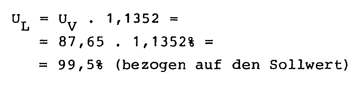
liegt an der unteren Grenze von 99,5% (bezogen auf den Sollwert) und somit innerhalb des zulässigen Bereichs.Assuming that the deviation ± δ% of the load voltage from the setpoint S, which is set to 100% here, may not exceed ± 0.5%, the supply voltage U V can drop to 87.65% of this setpoint because the transformer circuit according to the invention can raise this lowered supply voltage U V by 13.52% (based on U V = 100%); the resulting value for the load voltage of
lies at the lower limit of 99.5% (based on the setpoint) and thus within the permissible range.
Für die Schaltzustands-Kombination n = 13⁻ gilt entsprechend, daß hier die Versorgungsspannung UV auf 114,84% des Sollwerts angestiegen sein kann, ohne daß die Lastspannung
die obere Grenze 100,5% des zulässigen Bereichs übersteigt.For the switching state combination n = 13⁻ applies accordingly that here the supply voltage U V can have risen to 114.84% of the target value without the load voltage
the upper limit exceeds 100.5% of the permissible range.
Entsprechendes läßt sich für alle übrigen Schaltzustands-Kombinationen n erreichen. Dabei wird vorzugsweise immer bei solchen Werten der Versorgungsspannung UV von einer Schaltzustands-Kombination zur nächsten übergegangen, bei denen die Amplitude der Lastspannung ULvor vor dem Schalten und die Amplitude der Lastspannung ULnach nach dem Schalten zum Sollwert SL in etwa symmetrisch liegen. Aus den obigen Werten ergibt sich, daß bei diesem Ausführungsbeispiel Schwankungen der Versorgungsspannung UV von + Δ = + 14,84% (bezogen auf den Sollwert S = 100%) bis - Δ = - 13,35% (ebenfalls bezogen auf S = 100%) so kompensiert werden können, daß die Lastspannung UL nur innerhalb eines Bereiches von S ± 0,5% schwankt.The same can be achieved for all other switching state combinations n. In this case, preferably one always switches from one switching state combination to the next at values of the supply voltage U V in which the amplitude of the load voltage U L before switching and the amplitude of the load voltage U L after switching are approximately symmetrical to setpoint value S L. It follows from the above values that, in this exemplary embodiment, fluctuations in the supply voltage U V from + Δ = + 14.84% (based on the setpoint S = 100%) to - Δ = - 13.35% (also based on S = 100%) can be compensated so that the load voltage U L only fluctuates within a range of S ± 0.5%.
Soll ein größerer Schwankungsbereich ± Δ % erfaßt werden, muß entweder die minimale Amplitudenänderung A vergrößert werden, was auf Kosten der Regelgenauigkeit δ geht, oder es muß die Anzahl der Stufen vergrößert werden. Dabei kann es zweckmäßig sein, eine Stufe hinzuzufügen, deren Änderungsbereich nicht gleich der nächsten ganzzahligen Dreierpotenz von A, hier also nicht gleich ± 27A ist, sondern nur ein ganzzahliges Vielfaches kleiner 27 von A beträgt, das so groß ist, daß dann, wenn alle vier Stufen in derselben Richtung, d.h. alle additiv oder alle subtraktiv wirken, der geforderte Schwankungsbereich ± Δ gerade überdeckt werden kann.If a larger fluctuation range ± Δ% is to be detected, either the minimum amplitude change A must be increased, which is at the expense of the control accuracy δ, or the number of stages must be increased. It can be useful to add a level whose The change range is not equal to the next integer power of three of A, here is not equal to ± 27A, but is only an integer multiple less than 27 of A, which is so large that if all four stages are in the same direction, i.e. all additive or all act subtractively, the required fluctuation range ± Δ can just be covered.
Fig. 6 zeigt eine Abwandlung der erfindungsgemäßen Schaltungsanordnung, wie sie zur Steuerung der von einem Drei-Phasen-Netz abgegebenen Spannung Verwendung finden kann.Fig. 6 shows a modification of the circuit arrangement according to the invention, as it can be used to control the voltage output by a three-phase network.
Wie man der Fig. 6 entnimmt, ist für jeden der drei Phasenleiter R, S und T eine erfindungsgemäße Transformatorschaltung 75, 76, 77 vorgesehen, die jeweils in gleicher Weise aufgebaut ist, wie die Transformatorschaltung in Fig. 5. Es besteht also jede dieser drei Transformatorschaltungen 75, 76, 77 aus drei in Reihe geschalteten Stufen 55, 56, 57, von denen hier jede aus einem Stelleinheiten-Paar 34, 34' besteht und vier verschiedene Schaltzustände annehmen kann. Somit können der Wechselspannung auf jedem der drei Phasenleiter R, S und T Änderungsbeträge aufgeprägt werden, die zueinander im Verhältnis 1 : 3 : 9 stehen, oder es kann die Eingangswechselspannung unverändert weitergegeben werden oder es kann der Laststrom gedrosselt werden.As can be seen from FIG. 6, a
Um die Stufen der Transformatorschaltungen 75, 76, 77 in der erforderlichen Weise in die drei verschiedenen Schaltzustände bringen zu können, ist jede der Transformatorschaltungen 75, 76, 77 nicht nur mit ihrem zugehörigen Phasenleiter R, S bzw. T, sondern auch mit dem Null-Leiter N verbunden. Als Spannungsquelle dient hier ein Drei-Phasen-Netz 80.In order to be able to bring the stages of the
Die auf den einzelnen Phasenleitern R, S, T vom Netz 80 gelieferten Spannungsamplituden werden mit Hilfe einer Meßfühleranordnung 81 ständig gemessen, die die drei Meßsignale einer Komparatoranordnung 82 zuführt. Dort werden die Meßsignale mit einem gemeinsamen Referenzwert Uref verglichen. Alternativ kann auch für jeden Phasenleiter R, S und T ein eigener Referenzwert vorgegeben werden.The voltage amplitudes supplied by the
Der Komparator 82 erzeugt für jeden der drei Phasenleiter R, S, T ein eigenes Differenzsignal, das einer Schaltersteuerung 83 zugeführt wird. Diese steuert über die Leitungsgruppen 85, 86, 87, die Schalter der Stufen 55, 56, 57 in jeder der Transformatorschaltungen 75, 76, 77 in der Weise, wie dies oben ausführlich erläutert wurde. Selbstverständlich ist auch hier jede Stelleinheit über mehrere Leitungen mit der Schaltersteuerung 83 verbunden, wie dies in den Fig. 1 und 2 dargestellt ist. Der Einfachheit halber wurden in Fig. 6 diese Leitungen jedoch nur als eine einzige bidirektionale Leitung dargestellt.The
Den Ausgang einer jeden Transformatorschaltung 75, 76, 77 bildet ein Phasenleiter RK, SK bzw. TK, wobei der Buchstabe "K" andeutet, daß auf diesen Phasenleitern eine Wechselspannung mit konstant gehaltener Amplitude zur Verfügung steht. Diese Spannungen können entweder gemeinsam einer einzigen, einen Drei-Phasen-Strom benötigenden Last oder verschiedenen Lasten zugeführt werden, die jeweils nur mit einem 1-phasigen Wechselstrom betrieben werden müssen.The output of each
Alternativ kann auch bei einem Mehrphasensystem die Meßfühleranordnung 81 so ausgebildet sein, daß sie die auf den Phasenleitern RK, SK, TK der oder den Lasten zugeführten Wechselspannungen mißt.Alternatively, the
Bei größeren Anforderungen an die Regelgenauigkeit oder bei noch größeren Regelbereichen können auch bei den Transformatorschaltungen 75, 76, 77 mehr als drei Stufen vorgesehen werden. Analog zu Fig. 6 kann die erfindungsgemäße Schaltungsanordnung auch bei Mehrphasen-Systemen eingesetzt werden, die weniger oder mehr als drei Phasen umfassen.With greater demands on the control accuracy or with even larger control ranges, more than three stages can also be provided for the
Claims (36)
- A transformer circuit for producing an adjustable load voltage at a load from a supply voltage which is delivered by a voltage source, comprising at least one adjusting unit which includes the following components:- a transformer having a first winding which is disposed in series with the load, and at least one further winding, the turns ratio of which with respect to the first winding is greater than 1,- a terminal connecting conductor which is arranged downstream of the load as viewed from the first winding of the transformer and is in series with the load, and- switches by means of which the adjusting unit can be switched over between different switching states, wherein in at least one of said switching states applied to a further winding is a control ac voltage which induces in the first winding a voltage which is impressed on the input ac voltage in such a way that the amplitude of the output ac voltage differs from the amplitude of the input ac voltage by the amplitude of the induced voltage, and in a neutral switching state a further winding is switched into circuit in such a way that the output voltage of the adjusting unit is equal to the input voltage,
characterised in that in the neutral switching state by means of the switches (150, 151; 180, 181) the at least one further winding (11; 35, 36) is connected into a current path (150, 11, 151; 35, 180, 185, 181, 36) which is disposed electrically in parallel with the first winding (9) of the transformer (8). - A transformer circuit according to claim 1 wherein the transformer (8) includes a single further winding (11), characterised in that the adjusting unit (4) can be put into the two following switching states by means of the switches (150, 151, 152, 153):- an adding (first) switching state in which the further winding (11) is applied to the input voltage (UE) of the adjusting unit (4) with a sense of winding such that the voltage (ΔU₁) induced thereby in the first winding (9) is additively impressed on the input voltage (UE), and- a subtracting (second) switching state in which the further winding (11) is applied to the output voltage (UA) of the adjusting unit (4) with a sense of winding such that the voltage (ΔU₂) induced thereby in the first winding (9) is subtractively impressed on the input voltage (UE),
and that to produce the neutral (third) switching state the two ends (13, 14) of the further winding (11) can be connected by means of first and second switches (150, 151) to the two ends of the first winding (9). - A transformer circuit according to claim 2 characterised in that the two ends (13, 14) of the further winding (11) can be connected to the terminal connecting line (10) by way of a third switch (152) and a fourth switch (153) respectively and that the third and fourth switches (152, 153) are each in the form of a current limiting circuit in such a manner that in the closed condition they oppose only a low constant resistance to the current flowing through them as long as that current is less than a predetermined limit value and that said limit value is selected to be somewhat greater than the current which flows through the further winding (11) in the first or second switching state.
- A transformer circuit according to claim 2 characterised in that the two ends (13, 14) of the further winding (11) can be directly galvanically conductively connected to a further conductor (155) by way of a third switch (152) and a fourth switch (153) respectively and that provided between the further electric conductor (155) and the terminal connecting conductor (10) is a current limiting circuit arrangement (157) which electrically conductively connects together the two conductors (155, 10).
- A transformer circuit according to claim 4 characterised in that the current path (152, 155, 153) which connects together the two ends (13, 14) of the further winding (11) when the third and fourth switches (152, 153) are closed at the same time has an electrical resistance which is greater than the ohmic resistance of the further winding (11).
- A transformer circuit according to claim 1 characterised in that the transformer (8) includes two further windings (35, 36) of which the one is constantly connected as an adding winding (35) by its first end to the input terminal (2) of the adjusting unit (34), to which terminal the first winding (9) is connected, while the other of said two further windings is constantly connected as a subtracting winding (36) by its first end to the output terminal (5) of the adjusting unit (34), to which terminal the first winding (9) is connected, wherein the adjusting unit can be put into the following switching states by means of the switches (180, 181):- an adding (first) switching state in which only the adding further winding (35) is connected by its second end to the terminal connecting conductor (10) whereby induced in the first winding (9) is a voltage (ΔU₁) which is added to the input voltage (UE), and- a subtracting (second) switching state in which only the subtracting further winding (36) is connected by its second end to the terminal connecting conductor (10) whereby induced in the first winding (9) is a voltage (ΔU₂) which is subtracted from the input voltage (UE), and that in the neutral (third) switching state the two second ends of the two further windings (35, 36) are directly galvanically conductively connected to each other.
- A transformer circuit according to claim 6 characterised in that the two switches (180, 181) by which the two ends of the two further windings (35, 36) can be connected to the terminal connecting conductor (10) are directly galvanically conductively connected together by a further electric conductor (185) and that provided between said conductor (185) and the terminal connecting conductor (10) is a current limiting circuit arrangement (157) which electrically conductively connects the two conductors (185, 10) together.
- A transformer circuit according to one of claims 4, 5 and 7 characterised in that the circuit arrangement (157) is a switch which is closed in the first and second switching states of the adjusting unit (4, 34) and which is opened in the third switching state.
- A transformer circuit according to one of claims 4, 5 and 7 characterised in that the circuit arrangement (157) is a current limiting circuit which opposes a low constant resistance to the current flowing through it as long as said current is less than a predetermined limit value and that the limit value is selected to be somewhat greater than the current which flows in the first or second switching state through the respective further winding (11; 35, 36) connected to the control voltage.
- A transformer circuit according to claim 3 or claim 9 characterised in that the limit value of the current limiting circuit is variable.
- A transformer circuit according to claim 10 characterised in that for periods of time in which the adjusting unit is disposed for a longer period in the third switching state the current limiting circuit can be switched over to a second limit value which is substantially lower than the first limit value.
- A transformer circuit according to claim 11 characterised in that the second limit value is equal to zero.
- A transformer circuit according to claim 3 or one of claims 9 to 12 characterised in that the current limiting circuit regulates the current flowing therethrough, as it approaches the limit value, with a steady transition to said limit value.
- A transformer circuit according to claim 3 or one of claims 9 to 13 characterised in that the current limiting circuit (157) comprises two V-MOS-transistors (190, 191) whose source/drain paths are connected in series with mutually opposite polarities, and two resistors (192, 193) which are connected to each other and to the source/drain paths of the two transistors (190, 191) in series between the two transistors (190, 191), and that the gate voltage for the two transistors (190, 191) is applied to the connection point (195) of the two resistors (192, 193) and the respective gate terminal.
- A transformer circuit according to claim 14 characterised in that the current limiting circuit (157) comprises two diodes (198, 199) which are connected with mutually opposite polarities in series between the two current terminals (187, 188) of the current limiting circuit (157) and whose connection point (196) is electrically conductively connected to the connection point (195) of the two resistors (192, 193), wherein the forward direction of each diode (198, 199) is the same as the permanent forward direction of the V-MOS-transistor (190, 191) disposed in the respective parallel branch.
- A transformer circuit according to one of the preceding claims characterised in that the turns ratio of each further winding (11; 35, 36, 35', 36') of the transformer (8) relative to the first winding (9) is in a range of from 3:1 to 200:1.
- A transformer circuit according to one of the preceding claims characterised in that the transformer circuit comprises at least two stages (55, 56, 57)each of which comprises at least one adjusting unit (4; 34; 34, 34') and which are so connected together in series that the output ac voltage (UA) of the upstream stage (55, 56) is the input ac voltage (UE) of the downstream stage (56, 57) and that the at least two first windings (9) of the transformers (8) of the at least two stages (55, 56, 57) are directly disposed in series with each other.
- A transformer circuit according to claim 17 characterised in that each stage (55, 56, 57) includes at least two adjusting units (34, 34') which form an adjusting unit pair, wherein the turns ratios of the respective first windings (9, 9') with respect to the associated further windings (35, 36, 35', 36') are so matched to each other that the output voltage (UAP) of the adjusting unit pair (34, 34') is equal to the input voltage (UEP) of the adjusting unit pair (34, 34') when one (34) of the adjusting units additively impresses an induced voltage (ΔU₁) on its input voltage (UEP) and the other adjusting unit (34') subtractively impresses an induced voltage (ΔU₂) on its input voltage (UE).
- A transformer circuit according to claim 18 characterised in that the absolute values of the amplitude differences which can be produced at least by some of the stages (55, 56, 57) are related to each other in a relationship of integral powers of three 1:3:9: etc.
- A circuit arrangement comprising a transformer circuit according to one or more of claims 17 to 19 characterised in that there are provided an ac measuring sensor arrangement (64, 67; 81), a comparator arrangement (63, 66; 82) for comparing the output signals of the measuring sensor arrangement to reference values Uref1, Uref2, Uref), and a switch control means (23; 83) by which the switches of the stages (55, 56, 57) can be selectively actuated so that the load (7) is supplied with a load voltge (UL) at an amplitude which is as constant as possible.
- A circuit arrangement according to claim 20 characterised in that the measuring sensor arrangement comprises a measuring sensor (67; 81) which measures the supply voltage (UV) outputted by the voltage source (1; 80), and/or a measuring sensor (64) which measures the load voltage (UL).
- A circuit arrangement according to one of claims 20 and 21 characterised in that for each of the phase conductors (R, S, T) of a multi-phase system there are provided a transformer circuit (75, 76, 77) with one or more stages (55, 56, 57), a measuring sensor arrangement (81) for measuring the voltage on each of the phase conductors (R, S, T or RK, SK, TK), a comparator arrangement (82) for comparing the output signals of the measuring sensor arrangement (81) to at least one reference value (Uref), and a switch control means (83) which controls the switches of the stages (55, 56, 57) of all transformer circuits (75, 76, 77) on the basis of the difference signals outputted by the comparator arrangement (82).
- A transformer circuit for a multi-phase system with neutral conductor according to one of the preceding claims characterised in that for each phase it includes at least one adjusting unit (4; 34) whose first winding (9) is disposed in the respective phase conductor and whose terminal connecting conductor (10) is connected to the neutral conductor of the multi-phase system.
- A transformer circuit for a multi-phase system without neutral conductor according to one of Claims 1 to 22 characterised in that for each phase it includes at least one adjusting unit (4; 34) whose first winding (9) is disposed in the respective phase conductor and that the terminal connecting conductors (10) of all adjusting units are connected together to form an artificial neutral conductor.
- A transformer circuit for a multi-phase system without neutral conductor according to one of claims 1 to 22 characterised in that for each phase it includes at least one adjusting unit (4; 34) and that the adjusting units belonging to different phases are arranged in a linked circuit, wherein for each adjusting unit the first winding is in the associated phase conductor and the terminal connecting conductor (10) is formed by one of the other phase conductors.
- A method of switching over a transformer circuit which, for producing an adjusting load voltage at a load from a supply voltage delivered by a voltage source, has at least one adjusting unit which comprises the following components:- a transformer with a first winding disposed in series with the load and with at least one further winding, the turns ratio of which is greater than 1 relative to the first winding,- a terminal connecting conductor which is arranged downstream of the load as viewed from the first winding of the transformer and which is in series with the load, and- switches by means of which the adjusting unit can be switched over between different switching states, wherein in at least one of said switching states applied to a further winding is a control ac voltage which induces in the first winding a voltage which is impressed on the input ac voltage in such a way that the amplitude of the output ac voltage differs from the amplitude of the input ac voltage by the amplitude of the induced voltage, and in a neutral switching state a further winding can be switched into circuit so that the output voltage of the adjusting unit is equal to the input voltage, characterised in that in the neutral switching state by means of the switches (150, 151; 180, 181) the at least one further winding (11; 35, 36) is connected into a current path (150, 11, 151; 35, 180, 185, 181, 36) which is disposed electrically in parallel with the first winding (9) of the transformer (8).
- A method according to claim 26 for a transformer circuit having an adjusting unit (4) in which the transformer (8) includes a single further winding (11), characterised in that the adjusting unit (4) can be put into the two following switching states by means of the switches (150, 151, 152, 153):- an adding (first) switching state in which the further winding (11) is applied to the input voltage (UE) of the adjusting unit (4) with a sense of winding such that the voltage (ΔU₁) induced thereby in the first winding (9) is additively impressed on the input voltage (UE), and- a subtracting (second) switching state in which the further winding (11) is applied to the output voltage (UA ) of the adjusting unit (4) with a sense of winding such that the voltage (ΔU₂) induced thereby in the first winding (9) is subtractively impressed on the input voltage (UE),
and that to produce the neutral (third) switching state the two ends (13, 14) of the further winding (11) are connected by means of first and second switches (150, 151) to the two ends of the first winding (9). - A method according to claim 27 characterised in that the two ends (13, 14) of the further winding (11) can be connected to the terminal connecting conductor (10) by way of a third switch (152) and a fourth switch (153) respectively and that the third and fourth switches (152, 153) are each in the form of a current limiting circuit in such a manner that in the closed condition they oppose only a low constant resistance to the current flowing through them as long as that current is less than a predetermined limit value, that said limit value is selected to be somewhat greater than the current which flows through the further winding (11), in the first or second switching state, that the transition from the first to the second or from the second to the first switching state is effected, in each case with the temporary interposition of the third switching state, in that in the transition from the first switching state in which the first switch (150) and the fourth switch (153) are closed and the second switch (151) and the third switch (152) are opened, into the second switching state in which the second switch (151) and the third switch (152) are closed and the first switch (150) and the fourth switch (153) are opened, firstly the second switch (151) and the third switch (152) are closed and then the first switch (150) and the fourth switch (153) are opened, and that in the transition from the second to the first switching state, firstly the first switch (150) and the fourth switch (153) are closed and then the second switch (151) and the third switch (152) are opened.
- A method according to claim 27 characterised in that the third and fourth switches (152, 153) are directly galvanically conductively connected together by a further electric conductor (155), that provided between the further electric conductor (155) and the terminal connecting conductor (10) is a current limiting circuit arrangement (157) which electrically conductively connects the two conductors (155, 10) together and that the transition from the first to the second or from the second to the first switching state is effected, in each case with the temporary interposition of the third switching state, in that in the transition from the first switching state into the second switching state firstly the second switch (151) is closed, then the fourth switch (153) is opened, then the third switch (152) is closed and then the first switch (150) is opened, and that in the transition from the second to the first switching state firstly the first switch (150) is closed, then the third switch (152) is opened, then the fourth switch (153) is closed and then the second switch (151) is opened, so that the third and fourth switches (152, 153) are never simultaneously closed.
- A method according to claim 26 for a transformer circuit comprising an adjusting unit (34) in which the transformer (8) includes two further windings (35, 36) of which the one is constantly connected as an adding winding (35) by its first end to the input terminal (2) of the adjusting unit (34), to which terminal the first winding (9) is connected, while the other of said two further windings is constantly connected as a subtracting winding (36) by its first end to the output terminal (5) of the adjusting unit (34), to which terminal the first winding (9) is connected, characterised in that the adjusting unit can be put into the following switching states by means of the switches (180, 181):- an adding (first) switching state in which only the adding further winding (35) is connected by its second end to the terminal connecting conductor (10) whereby induced in the first winding (9) is a voltage (ΔU₁) which is added to the input voltage (UE), and- a subtracting (second) switching state in which only the subtracting further winding (36) is connected by its second end to the terminal connecting conductor (10) whereby induced in the first winding (9) is a voltage (ΔU₂) which is subtracted from the input voltage (UE), and that in the neutral (third) switching state the two second ends of the two further windings (35, 36) are directly galvanically conductively connected to each other.
- A method according to claim 30 characterised in that the two switches (180, 181) by which the two ends of the two further windings (35, 36) can be connected to the terminal connecting conductor (10) are directly galvanically conductively connected together by a further electric conductor (185), that provided between said conductor (185) and the terminal connecting conductor (10) is a current limiting circuit arrangement (157) which electrically conductively connects the two conductors (185, 10) together, that in the transition from the first switching state in which the switch (180) which is connected to the second end of the adding further winding (35) is closed and the switch (181) which is connected to the second end of the subtracting further winding (36) is opened into the second switching state in which the switch (180) which is connected to the second end of the adding further winding (35) is opened and the switch (181) which is connected to the second end of the subtracting further winding (36) is closed, firstly the switch (181) for the subtracting winding (36) is closed and thereafter the switch (180) for the adding winding (35) is opened, and that in the transition from the second to the first switching state firstly the switch (180) for the adding winding (35) is closed and thereafter the switch (181) for the subtracting winding (36) is opened.
- A method according to one of claims 26 to 31 characterised in that the switches (150, 151, 152, 153; 180, 181) used are electronic switches which can be closed and opened at any times and that the switches which must be opened for the transition from the third switching state to the first or second switching state are opened as precisely as possible at the ideal switching times at which the current which flows in the third switching state through the further winding (11; 35, 36) which is connected to its corresponding control voltage after the transition into the first or second switching state respectively is of the same value as the current which flows in said further winding (11; 35, 36) immediately after the switching operation.
- A method according to claim 32 characterised in that used as an approximation for the ideal switching times are the times for opening of the switches at which the current which flows in the first or second switching state through the further winding (11; 35, 36) which in that switching state is connected to its corresponding control voltage has a passage through zero.
- A method according to claim 33 characterised in that the time interval of a passage through zero of the current which in the first or second switching state flows through the further winding (11; 35, 36) which in that switching state is connected to its respective control voltage, from the preceding or in relation to the subsequent passage through zero of said control voltage is measured and the measurement value is stored, and that in later transitions from the third to the first or the second switching state said stored measurement value is used in order to determine the time for opening of the respective switches, beginning with a passage through zero of the control voltage.
- A method according to one of claims 26 to 34 for a transformer circuit which includes at least two stages of which each comprises at least one adjusting unit and which are so connected together in series that the output ac voltage of the upstream stage is the input ac voltage of the downstream stage, wherein the at least two first windings of the transformers of the at least two stages are disposed directly in series with each other, and wherein there are provided an ac voltage measuring sensor arrangement, a comparator arrangement for comparing the output signals of the measuring sensor arrangement with reference values, and a switch control means by which the switches of the stages can be selectively actuated so that the load receives a load voltage at an amplitude which is as constant as possible, characterised in that the absolute value of the smallest possible variation (A) in amplitude is between 1.0 times and 2.0 times the absolute value of the admissible deviation (δ) of the load voltage (UL) from the desired value (SL), and that the switching thresholds at which, with an increasing deviation in respect of the supply voltage (UV) which is outputted by the voltage source from the nominal ac voltage, the impressed amplitude difference is switched over from n-times the smallest possible change (A) in amplitude to (n+1)-times, and with a decreasing deviation it is switched over from (n-1)-times to n-times, are so selected that the amplitude values of the load voltage (UL) with a steady passage of the supply voltage (UV) through the respective switching threshold, lie symmetrically relative to the desired value (SL) before and after the switching-over operation.
- A method according to claim 35 characterised in that the load voltage (UL) is regulated to a desired value (SL) which is different from the nominal value (UVnenn) of the supply voltage (UV).
Priority Applications (1)
| Application Number | Priority Date | Filing Date | Title |
|---|---|---|---|
| AT85108921T ATE68611T1 (en) | 1984-07-24 | 1985-07-16 | TRANSFORMER CIRCUIT. |
Applications Claiming Priority (6)
| Application Number | Priority Date | Filing Date | Title |
|---|---|---|---|
| DE3427291 | 1984-07-24 | ||
| DE3427291 | 1984-07-24 | ||
| DE3502889 | 1985-01-29 | ||
| DE19853502889 DE3502889A1 (en) | 1984-07-24 | 1985-01-29 | Transformer circuit |
| DE3511182 | 1985-03-25 | ||
| DE19853511182 DE3511182A1 (en) | 1985-03-27 | 1985-03-27 | Transformer circuit |
Publications (3)
| Publication Number | Publication Date |
|---|---|
| EP0169488A2 EP0169488A2 (en) | 1986-01-29 |
| EP0169488A3 EP0169488A3 (en) | 1987-08-19 |
| EP0169488B1 true EP0169488B1 (en) | 1991-10-16 |
Family
ID=27192190
Family Applications (1)
| Application Number | Title | Priority Date | Filing Date |
|---|---|---|---|
| EP85108921A Expired - Lifetime EP0169488B1 (en) | 1984-07-24 | 1985-07-16 | Transformer circuit |
Country Status (3)
| Country | Link |
|---|---|
| US (1) | US4774451A (en) |
| EP (1) | EP0169488B1 (en) |
| DE (1) | DE3584401D1 (en) |
Families Citing this family (13)
| Publication number | Priority date | Publication date | Assignee | Title |
|---|---|---|---|---|
| JPH0729747Y2 (en) * | 1986-11-26 | 1995-07-05 | 株式会社東芝 | AC / DC converter |
| KR930010265B1 (en) * | 1991-05-14 | 1993-10-16 | 삼성전자 주식회사 | Stabilizing circuit for a microwave range |
| DE4431021C1 (en) * | 1994-08-31 | 1995-10-19 | Siemens Ag | Equivalent circuit for several functional units |
| JP2561055B2 (en) * | 1994-11-18 | 1996-12-04 | インターナショナル・ビジネス・マシーンズ・コーポレイション | Information processing apparatus and control method thereof |
| US6351106B1 (en) * | 2000-09-29 | 2002-02-26 | Silicon Power Corporation | Static voltage regulator and controller |
| WO2009058695A2 (en) * | 2007-10-30 | 2009-05-07 | Northrop Grumman Systems Corporation | Cool impact-ionization transistor and method for making same |
| RU2377630C1 (en) * | 2008-09-16 | 2009-12-27 | Лев Залманович Фейгин | Stabiliser of ac voltage with elements of protection and back-up (versions) |
| KR20110114697A (en) * | 2009-02-06 | 2011-10-19 | 에이비비 리써치 리미티드 | A hybrid distribution transformer with ac & dc power capabilities |
| EP2401805B1 (en) * | 2009-02-27 | 2017-04-05 | ABB Research Ltd. | A hybrid distribution transformer with an integrated voltage source converter |
| EP2549495B1 (en) * | 2011-07-18 | 2018-05-23 | ABB Schweiz AG | Dry type transformer |
| GB201313774D0 (en) * | 2013-08-01 | 2013-09-18 | Vphase Smart Energy Ltd | Apparatus and method for voltage control |
| CN112994549A (en) * | 2021-02-25 | 2021-06-18 | 上海交大海洋水下工程科学研究院有限公司 | Stabilizing device, method and medium for full-sea-depth ROV power supply |
| CN113258146B (en) * | 2021-03-29 | 2022-12-30 | 华为数字能源技术有限公司 | Battery system, driving system and energy storage container |
Family Cites Families (8)
| Publication number | Priority date | Publication date | Assignee | Title |
|---|---|---|---|---|
| US3621375A (en) * | 1970-04-16 | 1971-11-16 | Gen Electric | Voltage regulator with zero current static switching between tapped portions of the primary of a regulator transformer |
| US3621374A (en) * | 1970-04-16 | 1971-11-16 | Gen Electric | Voltage regulator with zero current static switching between taps for a regulator transformer |
| DE2233020A1 (en) * | 1971-07-06 | 1973-01-25 | Edward Cooper | AC AC VOLTAGE REGULATOR WITH MULTIPLE SWITCHING OF YOUR TAPS OF THE TRANSFORMER PRIMARY DEVELOPMENT |
| IT1010601B (en) * | 1974-03-11 | 1977-01-20 | Legnaioli L | ELECTRIC MACHINE TO CHANGE THE TRANSFORMATION RATIO OF A VOLTAGE WITH THE AID OF SWITCHES |
| GB1476699A (en) * | 1974-12-24 | 1977-06-16 | Matsushita Electric Ind Co Ltd | Power supply system |
| US3970918A (en) * | 1975-01-13 | 1976-07-20 | Edward Cooper | High speed, step-switching AC line voltage regulator with half-cycle step response |
| US4178539A (en) * | 1978-08-03 | 1979-12-11 | The Superior Electric Company | Stepping AC line voltage regulator |
| GB2043971B (en) * | 1979-03-13 | 1983-04-07 | Koffler R | Voltage regulators |
-
1985
- 1985-07-16 DE DE8585108921T patent/DE3584401D1/en not_active Expired - Fee Related
- 1985-07-16 EP EP85108921A patent/EP0169488B1/en not_active Expired - Lifetime
- 1985-07-22 US US06/757,831 patent/US4774451A/en not_active Expired - Fee Related
Also Published As
| Publication number | Publication date |
|---|---|
| EP0169488A3 (en) | 1987-08-19 |
| EP0169488A2 (en) | 1986-01-29 |
| US4774451A (en) | 1988-09-27 |
| DE3584401D1 (en) | 1991-11-21 |
Similar Documents
| Publication | Publication Date | Title |
|---|---|---|
| EP0382110B1 (en) | Output control circuit for reversers, and high-frequency power supply for the DC supply of a welding station | |
| EP0169488B1 (en) | Transformer circuit | |
| DE2338538B2 (en) | Circuit arrangement for regulated direct current supply | |
| DE4413546A1 (en) | DC control circuit | |
| DE3105636C2 (en) | ||
| DE3530966C2 (en) | ||
| DE2538493C3 (en) | High-voltage direct current transmission system protected against overcurrent | |
| DE3511182C2 (en) | ||
| DE1638316A1 (en) | Control circuit for the electronic commutation of an electric motor | |
| DE2504407C2 (en) | Chopper regulator | |
| DE2731501C3 (en) | Control arrangement for a direct current motor operated with series connection-shunt switching | |
| EP0243948B1 (en) | Control circuit for an arc lamp | |
| DE3502889C2 (en) | ||
| WO1998043266A1 (en) | Electromagnetic control device | |
| DE3546614C2 (en) | Transformer circuit | |
| DE19718814C2 (en) | Method and device for power control of electrical consumers connected to an AC supply network | |
| DE1928538A1 (en) | Voltage regulator for devices operated with alternating current, in particular stepless speed regulator for electric motors | |
| DE2852065C2 (en) | Control circuit for a speed-controlled direct current machine | |
| EP1170855B1 (en) | Discharge circuit | |
| DE1613775C3 (en) | Arrangement for controlling the speed of an AC motor operated by an inverter | |
| DE2827357A1 (en) | Control device for double static converter - has zero current signalling device with variable switching threshold depending on current actual value | |
| DE2003587B2 (en) | Circuit arrangement for controlling the average resistance of an electronic switching element by means of pulse width modulation | |
| DE2166454C3 (en) | Saturation reactor | |
| DE2736781C3 (en) | Circuit arrangement for regulating or controlling the excitation current of an electrical machine, in particular a DC machine | |
| DE741172C (en) | Device for the control or for the direct operation of apparatus used for voltage regulation |
Legal Events
| Date | Code | Title | Description |
|---|---|---|---|
| PUAI | Public reference made under article 153(3) epc to a published international application that has entered the european phase |
Free format text: ORIGINAL CODE: 0009012 |
|
| AK | Designated contracting states |
Designated state(s): AT CH DE FR GB IT LI NL SE |
|
| 17P | Request for examination filed |
Effective date: 19860724 |
|
| PUAL | Search report despatched |
Free format text: ORIGINAL CODE: 0009013 |
|
| AK | Designated contracting states |
Kind code of ref document: A3 Designated state(s): AT CH DE FR GB IT LI NL SE |
|
| RAP1 | Party data changed (applicant data changed or rights of an application transferred) |
Owner name: VOIGT & HAEFFNER GMBH |
|
| 17Q | First examination report despatched |
Effective date: 19890814 |
|
| GRAA | (expected) grant |
Free format text: ORIGINAL CODE: 0009210 |
|
| AK | Designated contracting states |
Kind code of ref document: B1 Designated state(s): AT CH DE FR GB IT LI NL SE |
|
| REF | Corresponds to: |
Ref document number: 68611 Country of ref document: AT Date of ref document: 19911115 Kind code of ref document: T |
|
| REF | Corresponds to: |
Ref document number: 3584401 Country of ref document: DE Date of ref document: 19911121 |
|
| ITF | It: translation for a ep patent filed |
Owner name: ING. DR. LAZZARO MARTINI S.R.L. |
|
| ET | Fr: translation filed | ||
| GBT | Gb: translation of ep patent filed (gb section 77(6)(a)/1977) | ||
| PLBE | No opposition filed within time limit |
Free format text: ORIGINAL CODE: 0009261 |
|
| STAA | Information on the status of an ep patent application or granted ep patent |
Free format text: STATUS: NO OPPOSITION FILED WITHIN TIME LIMIT |
|
| 26N | No opposition filed | ||
| PGFP | Annual fee paid to national office [announced via postgrant information from national office to epo] |
Ref country code: FR Payment date: 19930507 Year of fee payment: 9 |
|
| PGFP | Annual fee paid to national office [announced via postgrant information from national office to epo] |
Ref country code: SE Payment date: 19930514 Year of fee payment: 9 |
|
| PGFP | Annual fee paid to national office [announced via postgrant information from national office to epo] |
Ref country code: GB Payment date: 19930706 Year of fee payment: 9 |
|
| PGFP | Annual fee paid to national office [announced via postgrant information from national office to epo] |
Ref country code: CH Payment date: 19930721 Year of fee payment: 9 |
|
| PGFP | Annual fee paid to national office [announced via postgrant information from national office to epo] |
Ref country code: AT Payment date: 19930730 Year of fee payment: 9 |
|
| PGFP | Annual fee paid to national office [announced via postgrant information from national office to epo] |
Ref country code: NL Payment date: 19930731 Year of fee payment: 9 |
|
| PGFP | Annual fee paid to national office [announced via postgrant information from national office to epo] |
Ref country code: DE Payment date: 19930930 Year of fee payment: 9 |
|
| PG25 | Lapsed in a contracting state [announced via postgrant information from national office to epo] |
Ref country code: GB Effective date: 19940716 Ref country code: AT Effective date: 19940716 |
|
| PG25 | Lapsed in a contracting state [announced via postgrant information from national office to epo] |
Ref country code: SE Effective date: 19940717 |
|
| PG25 | Lapsed in a contracting state [announced via postgrant information from national office to epo] |
Ref country code: LI Effective date: 19940731 Ref country code: CH Effective date: 19940731 |
|
| EUG | Se: european patent has lapsed |
Ref document number: 85108921.9 Effective date: 19950210 |
|
| PG25 | Lapsed in a contracting state [announced via postgrant information from national office to epo] |
Ref country code: NL Effective date: 19950201 |
|
| GBPC | Gb: european patent ceased through non-payment of renewal fee |
Effective date: 19940716 |
|
| NLV4 | Nl: lapsed or anulled due to non-payment of the annual fee | ||
| PG25 | Lapsed in a contracting state [announced via postgrant information from national office to epo] |
Ref country code: FR Effective date: 19950331 |
|
| REG | Reference to a national code |
Ref country code: CH Ref legal event code: PL |
|
| PG25 | Lapsed in a contracting state [announced via postgrant information from national office to epo] |
Ref country code: DE Effective date: 19950401 |
|
| EUG | Se: european patent has lapsed |
Ref document number: 85108921.9 |
|
| REG | Reference to a national code |
Ref country code: FR Ref legal event code: ST |