DE102010015470A1 - Process for the internal coating of functional layers with a tempering material - Google Patents
Process for the internal coating of functional layers with a tempering material Download PDFInfo
- Publication number
- DE102010015470A1 DE102010015470A1 DE201010015470 DE102010015470A DE102010015470A1 DE 102010015470 A1 DE102010015470 A1 DE 102010015470A1 DE 201010015470 DE201010015470 DE 201010015470 DE 102010015470 A DE102010015470 A DE 102010015470A DE 102010015470 A1 DE102010015470 A1 DE 102010015470A1
- Authority
- DE
- Germany
- Prior art keywords
- layer
- base material
- pores
- precursor
- coating
- Prior art date
- Legal status (The legal status is an assumption and is not a legal conclusion. Google has not performed a legal analysis and makes no representation as to the accuracy of the status listed.)
- Withdrawn
Links
Images


Classifications
-
- B—PERFORMING OPERATIONS; TRANSPORTING
- B28—WORKING CEMENT, CLAY, OR STONE
- B28B—SHAPING CLAY OR OTHER CERAMIC COMPOSITIONS; SHAPING SLAG; SHAPING MIXTURES CONTAINING CEMENTITIOUS MATERIAL, e.g. PLASTER
- B28B19/00—Machines or methods for applying the material to surfaces to form a permanent layer thereon
-
- C—CHEMISTRY; METALLURGY
- C23—COATING METALLIC MATERIAL; COATING MATERIAL WITH METALLIC MATERIAL; CHEMICAL SURFACE TREATMENT; DIFFUSION TREATMENT OF METALLIC MATERIAL; COATING BY VACUUM EVAPORATION, BY SPUTTERING, BY ION IMPLANTATION OR BY CHEMICAL VAPOUR DEPOSITION, IN GENERAL; INHIBITING CORROSION OF METALLIC MATERIAL OR INCRUSTATION IN GENERAL
- C23C—COATING METALLIC MATERIAL; COATING MATERIAL WITH METALLIC MATERIAL; SURFACE TREATMENT OF METALLIC MATERIAL BY DIFFUSION INTO THE SURFACE, BY CHEMICAL CONVERSION OR SUBSTITUTION; COATING BY VACUUM EVAPORATION, BY SPUTTERING, BY ION IMPLANTATION OR BY CHEMICAL VAPOUR DEPOSITION, IN GENERAL
- C23C16/00—Chemical coating by decomposition of gaseous compounds, without leaving reaction products of surface material in the coating, i.e. chemical vapour deposition [CVD] processes
- C23C16/04—Coating on selected surface areas, e.g. using masks
- C23C16/045—Coating cavities or hollow spaces, e.g. interior of tubes; Infiltration of porous substrates
-
- C—CHEMISTRY; METALLURGY
- C23—COATING METALLIC MATERIAL; COATING MATERIAL WITH METALLIC MATERIAL; CHEMICAL SURFACE TREATMENT; DIFFUSION TREATMENT OF METALLIC MATERIAL; COATING BY VACUUM EVAPORATION, BY SPUTTERING, BY ION IMPLANTATION OR BY CHEMICAL VAPOUR DEPOSITION, IN GENERAL; INHIBITING CORROSION OF METALLIC MATERIAL OR INCRUSTATION IN GENERAL
- C23C—COATING METALLIC MATERIAL; COATING MATERIAL WITH METALLIC MATERIAL; SURFACE TREATMENT OF METALLIC MATERIAL BY DIFFUSION INTO THE SURFACE, BY CHEMICAL CONVERSION OR SUBSTITUTION; COATING BY VACUUM EVAPORATION, BY SPUTTERING, BY ION IMPLANTATION OR BY CHEMICAL VAPOUR DEPOSITION, IN GENERAL
- C23C16/00—Chemical coating by decomposition of gaseous compounds, without leaving reaction products of surface material in the coating, i.e. chemical vapour deposition [CVD] processes
- C23C16/22—Chemical coating by decomposition of gaseous compounds, without leaving reaction products of surface material in the coating, i.e. chemical vapour deposition [CVD] processes characterised by the deposition of inorganic material, other than metallic material
- C23C16/30—Deposition of compounds, mixtures or solid solutions, e.g. borides, carbides, nitrides
- C23C16/40—Oxides
- C23C16/403—Oxides of aluminium, magnesium or beryllium
-
- C—CHEMISTRY; METALLURGY
- C23—COATING METALLIC MATERIAL; COATING MATERIAL WITH METALLIC MATERIAL; CHEMICAL SURFACE TREATMENT; DIFFUSION TREATMENT OF METALLIC MATERIAL; COATING BY VACUUM EVAPORATION, BY SPUTTERING, BY ION IMPLANTATION OR BY CHEMICAL VAPOUR DEPOSITION, IN GENERAL; INHIBITING CORROSION OF METALLIC MATERIAL OR INCRUSTATION IN GENERAL
- C23C—COATING METALLIC MATERIAL; COATING MATERIAL WITH METALLIC MATERIAL; SURFACE TREATMENT OF METALLIC MATERIAL BY DIFFUSION INTO THE SURFACE, BY CHEMICAL CONVERSION OR SUBSTITUTION; COATING BY VACUUM EVAPORATION, BY SPUTTERING, BY ION IMPLANTATION OR BY CHEMICAL VAPOUR DEPOSITION, IN GENERAL
- C23C16/00—Chemical coating by decomposition of gaseous compounds, without leaving reaction products of surface material in the coating, i.e. chemical vapour deposition [CVD] processes
- C23C16/44—Chemical coating by decomposition of gaseous compounds, without leaving reaction products of surface material in the coating, i.e. chemical vapour deposition [CVD] processes characterised by the method of coating
- C23C16/455—Chemical coating by decomposition of gaseous compounds, without leaving reaction products of surface material in the coating, i.e. chemical vapour deposition [CVD] processes characterised by the method of coating characterised by the method used for introducing gases into reaction chamber or for modifying gas flows in reaction chamber
- C23C16/45523—Pulsed gas flow or change of composition over time
- C23C16/45525—Atomic layer deposition [ALD]
- C23C16/45555—Atomic layer deposition [ALD] applied in non-semiconductor technology
-
- F—MECHANICAL ENGINEERING; LIGHTING; HEATING; WEAPONS; BLASTING
- F01—MACHINES OR ENGINES IN GENERAL; ENGINE PLANTS IN GENERAL; STEAM ENGINES
- F01D—NON-POSITIVE DISPLACEMENT MACHINES OR ENGINES, e.g. STEAM TURBINES
- F01D5/00—Blades; Blade-carrying members; Heating, heat-insulating, cooling or antivibration means on the blades or the members
- F01D5/12—Blades
- F01D5/28—Selecting particular materials; Particular measures relating thereto; Measures against erosion or corrosion
- F01D5/288—Protective coatings for blades
-
- Y—GENERAL TAGGING OF NEW TECHNOLOGICAL DEVELOPMENTS; GENERAL TAGGING OF CROSS-SECTIONAL TECHNOLOGIES SPANNING OVER SEVERAL SECTIONS OF THE IPC; TECHNICAL SUBJECTS COVERED BY FORMER USPC CROSS-REFERENCE ART COLLECTIONS [XRACs] AND DIGESTS
- Y10—TECHNICAL SUBJECTS COVERED BY FORMER USPC
- Y10T—TECHNICAL SUBJECTS COVERED BY FORMER US CLASSIFICATION
- Y10T428/00—Stock material or miscellaneous articles
- Y10T428/249921—Web or sheet containing structurally defined element or component
- Y10T428/249953—Composite having voids in a component [e.g., porous, cellular, etc.]
- Y10T428/249967—Inorganic matrix in void-containing component
- Y10T428/249969—Of silicon-containing material [e.g., glass, etc.]
-
- Y—GENERAL TAGGING OF NEW TECHNOLOGICAL DEVELOPMENTS; GENERAL TAGGING OF CROSS-SECTIONAL TECHNOLOGIES SPANNING OVER SEVERAL SECTIONS OF THE IPC; TECHNICAL SUBJECTS COVERED BY FORMER USPC CROSS-REFERENCE ART COLLECTIONS [XRACs] AND DIGESTS
- Y10—TECHNICAL SUBJECTS COVERED BY FORMER USPC
- Y10T—TECHNICAL SUBJECTS COVERED BY FORMER US CLASSIFICATION
- Y10T428/00—Stock material or miscellaneous articles
- Y10T428/249921—Web or sheet containing structurally defined element or component
- Y10T428/249953—Composite having voids in a component [e.g., porous, cellular, etc.]
- Y10T428/249967—Inorganic matrix in void-containing component
- Y10T428/24997—Of metal-containing material
Abstract
Im Rahmen der Erfindung wurde ein Verfahren zur Innenbeschichtung der Poren einer porösen Funktionsschicht aus einem Basismaterial mit einem Vergütungsmaterial, das die Diffusion des Basismaterials und/oder die Reaktivität des Basismaterials mit seiner Umgebung herabsetzt, entwickelt. Erfindungsgemäß wird das Vergütungsmaterial aus der Gasphase auf den inneren Oberflächen der Poren abgeschieden. Es wurde erkannt, dass durch das Abscheiden aus der Gasphase das Vergütungsmaterial deutlich tiefer in das Porensystem der Funktionsschicht eingebracht werden kann, als dies nach dem bisherigen Stand der Technik möglich war. Dies gilt insbesondere, wenn nicht das Vergütungsmaterial selbst in das Porensystem eingebracht wird, sondern ein oder zwei Precursoren desselben, aus denen erst an den inneren Oberflächen der Poren das eigentliche Vergütungsmaterial entsteht.In the context of the invention, a method for the inner coating of the pores of a porous functional layer made of a base material with a coating material which reduces the diffusion of the base material and / or the reactivity of the base material with its surroundings was developed. According to the invention, the compensation material is deposited from the gas phase on the inner surfaces of the pores. It was recognized that the deposition from the gas phase enables the coating material to be introduced significantly deeper into the pore system of the functional layer than was possible according to the prior art. This applies in particular if the coating material itself is not introduced into the pore system, but rather one or two precursors of the same, from which the actual coating material is only created on the inner surfaces of the pores.
Description
Die Erfindung betrifft ein Verfahren zur Innenbeschichtung von Funktionsschichten mit einem Vergütungsmaterial.The invention relates to a method for internal coating of functional layers with a compensation material.
Stand der TechnikState of the art
Bauteile für den Hochtemperatureinsatz, wie beispielsweise Turbinenschaufeln für Gasturbinen, bestehen aus Grundwerkstoffen, die entsprechend der an das Bauteil zu stellenden mechanischen Anforderungen ausgewählt werden. Dies können beispielsweise warmfeste Stähle sein. Da der Wirkungsgrad etwa einer Gasturbine gemäß den Grundgesetzen der Thermodynamik mit zunehmender Betriebstemperatur deutlich ansteigt, besteht ein Bedürfnis, die Betriebstemperatur über die Temperatur hinaus zu steigern, bis zu der der Grundwerkstoff stabil bleibt. Hierfür wird das Bauteil mit einer porösen Wärmedämmschicht versehen.Components for high-temperature use, such as turbine blades for gas turbines, consist of base materials that are selected according to the mechanical requirements to be placed on the component. These can be, for example, heat-resistant steels. Since the efficiency of, for example, a gas turbine increases significantly with increasing operating temperature in accordance with the basic laws of thermodynamics, there is a need to increase the operating temperature beyond the temperature up to which the base material remains stable. For this purpose, the component is provided with a porous thermal barrier coating.
Nachteilig unterliegt eine solche Wärmedämmschicht im fortwährenden Hochtemperatureinsatz in der Regel einem irreversiblen Alterungsprozess, bis sie schließlich vom Bauteil abplatzt. Das Bauteil muss dann aufwändig ausgebaut und neu beschichtet werden, wenn es auf Grund der lokal fehlenden Wärmedämmschicht nicht gleich endgültig versagt.The disadvantage of such a thermal barrier coating in continuous high-temperature use usually an irreversible aging process until it finally flakes off the component. The component then has to be extensively removed and recoated if it does not fail completely due to the lack of a local thermal barrier coating.
Aus der
Die damit erzielbare Eindringtiefe des Vergütungsmaterials in das Porensystem des Basismaterials und die mit dem Vergütungsmaterial erzielbare Verbesserung der Dauerhaltbarkeit von Wärmedämmschichten ist spürbar, jedoch ist ohne Zweifel auch Verbesserungspotential erkennbar.The achievable penetration depth of the remuneration material in the pore system of the base material and the achievable with the compensation material improvement in the durability of thermal barrier coatings is noticeable, but is undoubtedly also improvement potential recognizable.
Aufgabe und LösungTask and solution
Aufgabe der Erfindung ist daher, ein Verfahren zur Verfügung zu stellen, mit dem das Vergütungsmaterial tiefer in das Porensystem des Basismaterials eingebracht werden kann und mit dem es in einer Weise eingebracht werden kann, dass es eine größere Wirkung auf die Dauerhaltbarkeit der Schicht hat.The object of the invention is therefore to provide a method by which the tempering material can be introduced deeper into the pore system of the base material and with which it can be introduced in such a way that it has a greater effect on the durability of the layer.
Diese Aufgabe wird erfindungsgemäß gelöst durch ein Verfahren gemäß Hauptanspruch. Weitere vorteilhafte Ausgestaltungen ergeben sich aus den darauf rückbezogenen Unteransprüchen.This object is achieved by a method according to the main claim. Further advantageous embodiments will be apparent from the dependent claims.
Gegenstand der ErfindungSubject of the invention
Im Rahmen der Erfindung wurde ein Verfahren zur Innenbeschichtung der Poren einer porösen Funktionsschicht aus einem Basismaterial mit einem Vergütungsmaterial, das die Diffusion des Basismaterials und/oder die Reaktivität des Basismaterials mit seiner Umgebung herabsetzt, entwickelt. Erfindungsgemäß wird das Vergütungsmaterial aus der Gasphase auf den inneren Oberflächen der Poren abgeschieden.In the context of the invention, a method has been developed for coating the pores of a porous functional layer comprising a base material with a tempering material, which reduces the diffusion of the base material and / or the reactivity of the base material with its surroundings. According to the invention, the tempering material is deposited from the gas phase on the inner surfaces of the pores.
Es wurde erkannt, dass durch das Abscheiden aus der Gasphase das Vergütungsmaterial deutlich tiefer in das Porensystem der Funktionsschicht eingebracht werden kann, als dies nach dem bisherigen Stand der Technik möglich war.It was recognized that the coating material can be introduced much deeper into the pore system of the functional layer by deposition from the gas phase, as was possible in the prior art.
Wärmedämmschichten, Schutzschichten, Einlaufschichten und andere Funktionsschichten für den Hochtemperatureinsatz werden porös ausgestaltet, damit sie einerseits gut auf dem beschichteten Bauteil haften und andererseits dehnungstolerant auf Temperaturänderungen reagieren können. Bei Betriebstemperaturen von 1000°C oder mehr, häufig sogar von 1300°C oder mehr, kommt es zu einer Relaxation der Spannungen in der Funktionsschicht. Vorteilhaft wird daher ein Basismaterial mit einer Schmelztemperatur oberhalb von 1000°C, bevorzugt oberhalb von 2000°C, gewählt. Kühlt das Bauteil von der Betriebstemperatur ab, zieht sich das Bauteil schneller zusammen als die Funktionsschicht, weil es in der Regel einen größeren thermischen Ausdehnungskoeffizienten hat als die Funktionsschicht. Es wurde erkannt, dass die Porosität sowie die Mikrorisse in der Funktionsschicht den Spielraum zur Verfügung stellt, innerhalb dessen die beim Abkühlen entstehende mechanische Spannung innerhalb der Funktionsschicht sowie zwischen der Funktionsschicht und dem Bauteil zumindest teilweise kompensiert werden kann.Thermal barrier coatings, protective layers, run-in layers and other functional layers for high-temperature use are designed to be porous so that, on the one hand, they adhere well to the coated component and, on the other hand, can react to temperature changes in a strain-tolerant manner. At operating temperatures of 1000 ° C or more, often even 1300 ° C or more, there is a relaxation of the stresses in the functional layer. Advantageously, therefore, a base material having a melting temperature above 1000 ° C, preferably above 2000 ° C, is selected. If the component cools from the operating temperature, the component contracts faster than the functional layer, because it usually has a larger thermal expansion coefficient than the functional layer. It has been recognized that the porosity as well as the microcracks in the functional layer provide the latitude within which the mechanical stress arising during cooling can be at least partially compensated within the functional layer and between the functional layer and the component.
Vorteilhaft wird daher ein Basismaterial mit einer Porosität von 5 Vol.-% oder mehr, bevorzugt zwischen 15 und 20 Vol.-%, für die erfindungsgemäße Beschichtung ausgewählt. Besonders Basismaterialien mit einer Porenverteilung mit Porendurchmessern von unter 1 Mikrometer und hohen Aspektverhältnissen (Tiefe der Pore) sind vorteilhaft mit diesem Verfahren zu beschichten. Solche Porenverteilungen liegen häufig bei thermisch gespritzten Schichten vor.Therefore, a base material having a porosity of 5% by volume or more, preferably between 15 and 20% by volume, is advantageous inventive coating selected. Especially base materials with a pore distribution with pore diameters of less than 1 micron and high aspect ratios (depth of the pore) are advantageous to coat with this method. Such pore distributions are often present in thermally sprayed layers.
Das erfindungsgemäße Verfahren ist insbesondere geeignet für ein poröses Basismaterial mit einer derartigen Porenverteilung, bei der die Poren mit einem Porendurchmesser von weniger als 1 Mikrometer, typischerweise zu mehr als 40%, zur Porosität beitragen, insbesondere zu mehr als 60%. Das bedeutet, ein Großteil der Porosität liegt im Bereich unter 1 Mikrometer. Ähnliche Porengrößenverteilung findet man auch in EB-PVD-Schichten, das bedeutet Basisschichten, die mit Hilfe des Electron-Beam Physical Vapor Deposition-Verfahrens aufgebracht wurden. Allgemein können als Basisschichten alle Wärmedämmschichten in Betracht gezogen werden.The method according to the invention is particularly suitable for a porous base material with such a pore distribution, in which the pores having a pore diameter of less than 1 micron, typically more than 40%, contribute to the porosity, in particular more than 60%. This means that a large part of the porosity is in the range below 1 micrometer. Similar pore size distributions are also found in EB PVD layers, that is, base layers deposited using the Electron Beam Physical Vapor Deposition method. In general, all thermal barrier coatings can be considered as base layers.
Mit zunehmender Betriebsdauer neigt das Basismaterial der Funktionsschicht in der Regel zur Sinterung. Die Körner des Basismaterials berühren sich über Kontaktflächen, die Bereiche mit starker Krümmung, also engen Krümmungsradien, aufweisen. Bei Betriebstemperatur ist nun die Diffusion von Atomen oder Molekülen des Basismaterials erleichtert. Das Basismaterial neigt dazu, aus der Kontaktfläche in die Krümmungszone zu diffundieren, um die Krümmung einzuebnen und somit die potentielle Energie dieser Krümmungszone zu minimieren. Dadurch wird die Kontaktfläche vergrößert. Dieser Effekt wird verstärkt durch einen Materialtransport entlang der Oberfläche der Krümmungszone hin zu dem Ort, wo die Krümmung am größten ist und durch das verlagerte Material am meisten potentielle Energie abgebaut werden kann. Dies führt zu einer beständigen Vergrößerung der Kontaktflächen zwischen den Körnern sowie teilweise zu einem Verschließen der Poren des Materials. Damit steigt das E-Modul des Materials in der Schicht und damit die Spannungen und gleichzeitig verschwindet die Möglichkeit des Spannungsabbaus durch Mikrorisse. Das Material der Funktionsschicht wird immer weniger widerstandsfähig gegen diese Belastung und platzt schließlich ab, wenn die gespeicherte elastische Energie die Energiefreisetzungsrate des Systems übersteigt. Weil das Basismaterial durch das zunehmende Verschließen der Poren verdichtet wird, ist der Alterungsprozess als progressive Schrumpfung (Sinterschrumpfung) des Basismaterials makroskopisch beobachtbar.As the operating time increases, the base material of the functional layer generally tends to sinter. The grains of the base material touch via contact surfaces, which have areas with strong curvature, ie narrow radii of curvature. At operating temperature, the diffusion of atoms or molecules of the base material is now facilitated. The base material tends to diffuse from the contact surface into the curvature zone to level the curvature and thus minimize the potential energy of that curvature zone. This increases the contact area. This effect is enhanced by transporting material along the surface of the curvature zone to where the curvature is greatest and where the most potential energy can be dissipated by the displaced material. This leads to a constant increase in the contact surfaces between the grains and partly to a closure of the pores of the material. This increases the modulus of elasticity of the material in the layer and thus the tensions and at the same time the possibility of stress relaxation disappears due to microcracks. The material of the functional layer becomes less and less resistant to this load and finally bursts off when the stored elastic energy exceeds the energy release rate of the system. Because the base material is compacted by the increasing closure of the pores, the aging process is macroscopically observable as progressive shrinkage (sintering shrinkage) of the base material.
An dieser Stelle setzt die Wirkung der Erfindung an. Das besonders tief in das Porensystem der Funktionsschicht eingebrachte Vergütungsmaterial bildet in den Krümmungszonen zwischen den Körnern eine Barriere gegen eine Diffusion der Atome oder Moleküle des Basismaterials und schützt das Basismaterial zugleich vor aggressiven Betriebsatmosphären. Dazu weist es vorteilhaft eine langsame Diffusionskonstante für die Atome oder Moleküle des Basismaterials auf. Diese sollte vorteilhaft kleiner als 10–15 m2/s sein.At this point, the effect of the invention begins. The compensation material introduced particularly deeply into the pore system of the functional layer forms a barrier in the bending zones between the grains against diffusion of the atoms or molecules of the base material and at the same time protects the base material from aggressive operating atmospheres. For this purpose, it advantageously has a slow diffusion constant for the atoms or molecules of the base material. This should be advantageously less than 10 -15 m 2 / s.
In thermisch gespritzten Basisschichten kann eine Beschichtung beispielsweise ohne weiteres bis in Tiefen von 50 Mikrometern erfolgen. Besonders vorteilhaft hat sich dabei eine Beschichtung über das ALD-Verfahren (Atomic Layer Deposition) herausgestellt Vorteilhaft weist das Vergütungsmaterial auch einen niedrigen Selbstdiffusionskoeffizienten auf. Da dieser häufig mit dem Schmelzpunkt korreliert, sind hier Materialien mit hohen Schmelzpunkten, vorzugsweise oberhalb 2000°C, auszuwählen.For example, in thermally sprayed basecoats, a coating can readily be down to depths of 50 microns. In this case, a coating has proven to be particularly advantageous over the ALD method (Atomic Layer Deposition). Advantageously, the tempering material also has a low self-diffusion coefficient. Since this often correlates with the melting point, materials with high melting points, preferably above 2000 ° C, are to be selected here.
Weiterhin ist es vorteilhaft, wenn das Vergütungsmaterial weitgehend inert bezüglich des Basismaterials – hier ist eine geringe Löslichkeit günstig – und bezüglich der Umgebung insbesondere inert bezüglich der im Betrieb an der Funktionsschicht vorgelegten Atmosphäre ist. Daher sind beispielsweise bei einer geplanten Luftatmosphäre im Betrieb oxidische Werkstoffe als Vergütungsmaterialien vorteilhaft.Furthermore, it is advantageous if the tempering material is largely inert with respect to the base material - in this case a low solubility is favorable - and in particular is inert with respect to the environment with respect to the atmosphere submitted during operation to the functional layer. Therefore, for example, in a planned air atmosphere in operation oxidic materials are advantageous as a remuneration materials.
Das Vergütungsmaterial dringt in der Regel nicht nur tiefer in das Porensystem ein, sondern entfaltet dort auch eine bessere Wirkung, als das nach dem Stand der Technik in Pulverform aus der Flüssigphase eingebrachte Vergütungsmaterial.The tempering material usually penetrates not only deeper into the pore system, but there also develops a better effect than the prior art in powder form from the liquid phase introduced compensation material.
Die über das erfindungsgemäße Verfahren hergestellten Funktionsschichten weisen in der Regel eine hohe Dichte (Porositäten von weniger als 2 Vol.-%), eine hohe Schichtdickenhomogenität und je nach Beschichtungstemperatur ein globulares bis kolumnares Gefüge auf. Speziell die ersten beiden Schichtmerkmale sind mit Flüssigphaseninfiltration (z. B. Sol-Gel) aus dem Stand der Technik aufgrund der unterschiedlichen Krümmungsradien der Oberflächen und der damit verbundenen unterschiedlichen Kapillarkräfte regelmäßig nicht zu erreichen. Im Rahmen der Erfindung wird unter einer homogenen Schichtdicke der Effekt verstanden, dass der Unterschied zwischen der Schichtdicke am Poreneingang und der in Tiefe von einem Mehrfachen des Porendurchmessers sehr gering ist, insbesondere kleiner als 10%, und zwar auch für Poren mit einem Porendurchmesser von weniger als 1 μm (Submikrometerbereich). Auch die hohe Dichte ist rissfrei schwer erzielbar und würde typischerweise bei alternativen Aufbringungsverfahren hohe Sintertemperaturen erfordern.The functional layers produced by the process according to the invention generally have a high density (porosities of less than 2% by volume), a high layer thickness homogeneity and, depending on the coating temperature, a globular to columnar structure. Especially the first two layer features can not be regularly achieved with liquid phase infiltration (eg sol-gel) from the prior art due to the different radii of curvature of the surfaces and the associated different capillary forces. In the context of the invention, a homogeneous layer thickness is understood to mean the effect that the difference between the layer thickness at the pore entrance and the depth of a multiple of the pore diameter is very small, in particular less than 10%, even for pores having a pore diameter of less than 1 μm (submicron range). Even the high density is difficult to achieve without cracking and would typically require high sintering temperatures in alternative application processes.
Erfindungsgemäß ist es möglich, Innenbeschichtungen von porösen Wärmedämmschichtsystemen umfassend oxidkeramische Werkstoffe (Zirkondioxid mit verschiedenen Stabilisatoren (z. B. YSZ), Pyrochlore, Perowskite, Aluminate, Spinelle, Silikate u. a.) mit stabilen Werkstoffen (Oxide, Aluminiumoxide, Zirkoniumoxide, Pyrochlore, Perowskite, Aluminate, Spinelle u. a.) herzustellen.According to the invention, it is possible to provide internal coatings of porous thermal barrier coating systems comprising oxide-ceramic materials (zirconium dioxide with various stabilizers (eg YSZ), pyrochlors, perovskites, aluminates, spinels, Silicates, etc.) with stable materials (oxides, aluminum oxides, zirconium oxides, pyrochlors, perovskites, aluminates, spinels, etc.).
Ferner sind auch Innenbeschichtungen von porösen Schutzschichtsystemen von keramischen (Faserverbund-) Werkstoffen (Environmental Barrier Coatings (EBCs) möglich. Die oxidkeramischen Schutzschichtwerkstoffe können sein: Zirkondioxid mit verschiedenen Stabilisatoren (z. B. YSZ), Pyrochlore, Perowskite, Aluminate, Spinelle, Silikate u. a.. Die Infiltrationswerkstoffe sind vorteilhaft aus der Gruppe der Oxide, speziell Aluminiumoxide, Zirkoniumoxide, Pyrochlore, Perowskite, Aluminate, Spinelle u. a. gewählt.Furthermore, internal coatings of porous protective coating systems of ceramic (fiber composite) materials (EBCs) are possible.The oxide ceramic protective coating materials may be: zirconium dioxide with various stabilizers (eg YSZ), pyrochlors, perovskites, aluminates, spinels, silicates The infiltration materials are advantageously selected from the group of oxides, especially aluminum oxides, zirconium oxides, pyrochlors, perovskites, aluminates, spinels and the like.
Das erfindungsgemäße Verfahren ermöglicht darüber hinaus eine Innenbeschichtung von auf komplexen Bauteilen (Turbinenschaufeln, Brennkammerelementen oder Übergangsstücken von Gastubinen) aufgebrachten Beschichtungen, wie z. B. eine Wärmedämmschicht, derart, dass die Innenbeschichtung vorteilhaft an der Stelle die größte Schichtdicke aufweist, an der in der Regel die heißesten Regionen auftreten.The inventive method also allows an inner coating of complex components (turbine blades, combustion chamber elements or transition pieces of gasubines) applied coatings such. Example, a thermal barrier coating, such that the inner coating advantageously at the point has the largest layer thickness at which usually the hottest regions occur.
Die Wirkung der hergestellten Funktionsschicht als Diffusionsbarriere hängt entscheidend davon ab, wie gut gerade die stark gekrümmten Bereiche an den Kontaktflächen, über die sich die Körner des Basismaterials berühren, mit dem Vergütungsmaterial benetzt werden. Die aus der Gasphase zuführbaren kleinsten Einheiten an Vergütungsmaterial sind beispielsweise Cluster, Moleküle oder gar einzelne Atome. Mit diesen kleinsten Einheiten lassen sich die gekrümmten Bereiche der Kontaktflächen deutlich dichter gegen Diffusion und Korrosion abschließen, als mit noch so fein gemahlenen Pulverkörnern.The effect of the produced functional layer as a diffusion barrier crucially depends on how well the strongly curved areas at the contact surfaces, over which the grains of the base material touch, are wetted with the tempering material. The smallest units of compensation material which can be supplied from the gas phase are, for example, clusters, molecules or even individual atoms. With these smallest units, the curved areas of the contact surfaces can be sealed significantly more tightly against diffusion and corrosion than with even finely ground powder grains.
In einer einfachen Ausführungsform kann das Vergütungsmaterial durch PVD (Physical Vapour Deposition) in die Poren eingebracht werden. In diesem Fall können im Wesentlichen diejenigen inneren Oberflächenbereiche der Poren mit dem Vergütungsmaterial beschichtet werden, die von der Quelle des Vergütungsmaterials aus in direkter Sichtlinie einsehbar sind (line-of-sight Beschichtung).In a simple embodiment, the compensation material can be introduced into the pores by PVD (Physical Vapor Deposition). In this case, substantially those inner surface areas of the pores can be coated with the tempering material, which are visible from the source of the remuneration material in the direct line of sight (line-of-sight coating).
In einer vorteilhaften Ausgestaltung der Erfindung wird das Vergütungsmaterial in einem Inertgasstrom in die Poren eingebracht. Auf diese Weise kann der Bereich des Porensystems, der mit PVD beschichtet werden kann, vorteilhaft über die direkte Sichtlinie hinaus erweitert werden (Hochfluss-PVD).In an advantageous embodiment of the invention, the compensation material is introduced into the pores in an inert gas stream. In this way, the area of the pore system that can be PVD coated can advantageously be extended beyond the direct line of sight (high flux PVD).
In einer besonders vorteilhaften Ausgestaltung der Erfindung wird ein Precursor in die Poren eingebracht, der an den inneren Oberflächen der Poren mit dem Basismaterial zum Vergütungsmaterial reagiert und/oder sich zum Vergütungsmaterial zersetzt. Ein geeigneter Precursor ist dabei ausreichend flüchtig, ist in der Gasphase stabil und reagiert nur mit dem Substrat bzw. der wachsenden Oberfläche zu einem inerten Zwischenprodukt. Dann kann das Vergütungsmaterial jenseits der direkten Sichtlinie zu seiner Quelle weite Strecken innerhalb des Porensystems zurücklegen, ehe es an einer Stelle auf das Basismaterial auftrifft und sich dort anlagert. Die Reaktion bzw. das Zersetzen kann beispielsweise dadurch ausgelöst werden, dass das Basismaterial sich auf erhöhter Temperatur befindet und dem auftreffenden Vergütungsmaterial so die Aktivierungsenergie für die Reaktion bzw. Zersetzung liefert. Diese Ausgestaltung ist eine Variante des CVD-Verfahrens (Chemical Vapour Deposition). Es lassen sich Innenbeschichtungen von Poren im Submillimeterbereich erzielen. Submillimeterbereich bedeutet hier, Porendurchmesser kleiner als 1 mm, jedoch größer als ein Mikrometer (> 1 μm).In a particularly advantageous embodiment of the invention, a precursor is introduced into the pores, which reacts on the inner surfaces of the pores with the base material to the compensation material and / or decomposes to the remuneration material. A suitable precursor is sufficiently volatile, is stable in the gas phase and reacts only with the substrate or the growing surface to an inert intermediate. Then, beyond the direct line of sight to its source, the annealing material can travel long distances within the pore system before it hits and attaches to the base material at one location. The reaction or decomposition can be triggered, for example, by the base material being at an elevated temperature and thus providing the starting material with the compensation energy for the reaction or decomposition. This embodiment is a variant of the CVD process (Chemical Vapor Deposition). It is possible to achieve interior coatings of pores in the submillimeter range. Submillimeter range here means pore diameter smaller than 1 mm, but larger than a micrometer (> 1 micron).
In einer weiteren besonders vorteilhaften Ausgestaltung der Erfindung wird zunächst ein erster Precursor PA in die Poren eingebracht, welcher sich an den inneren Oberflächen der Poren an das Basismaterial anlagert und/oder mit diesem reagiert, so dass eine Schicht A ausgebildet wird. Dabei lagert sich der Precursor PA auf der Schicht A nicht an und reagiert auch nicht mit dieser. Anschließend wird ein zweiter Precursor PB in die Poren eingebracht, welcher sich an der Schicht A anlagert und/oder mit dieser reagiert, so dass eine Schicht AB ausgebildet wird. Dabei lagert sich der Precursor PB auf der Schicht AB nicht an und reagiert auch nicht mit dieser. Diese Ausgestaltung ist eine Variante des ALD-Verfahrens (Atomic Lager Deposition).In a further particularly advantageous embodiment of the invention, a first precursor PA is first introduced into the pores, which accumulates on the inner surfaces of the pores on the base material and / or reacts with it, so that a layer A is formed. In this case, the precursor PA does not deposit on the layer A and does not react with it. Subsequently, a second precursor PB is introduced into the pores, which attaches to the layer A and / or reacts with it, so that a layer AB is formed. In this case, the precursor PB does not deposit on the layer AB and does not react with it. This embodiment is a variant of the ALD method (Atomic Lager Deposition).
Mit Hilfe eines ALD-Verfahrens ist es vorteilhaft möglich, auch ein Basismaterial mit Porendurchmessern im Bereich von kleiner als 1 μm (Submikrometerbereich) bis in die Tiefe zu beschichtenWith the aid of an ALD method, it is advantageously possible to coat even a base material with pore diameters in the range of less than 1 μm (submicron range) down to the depth
Es wurde erkannt, dass bei Beschichtungen nach dem Stand der Technik mit nur einem Precursor eine Tendenz dahingehend besteht, dass die der Quelle des Precursors am nächsten gelegenen Teile des Porensystems besonders dick innenbeschichtet werden. Poren mit Durchmessern im Submikrometerbereich werden auf diese Weise schnell verschlossen, so dass die tieferen Bereiche des Porensystems für den Precursor nicht mehr erreichbar sind. Poren mit Durchmessern in dieser Größenordnung treten typischerweise z. B. in plasmagespritzten Keramikschichten, wie Yttrium-stabilisiertem Zirkonoxid (YSZ), auf.It has been recognized that in prior art coatings with only one precursor there is a tendency for the parts of the pore system closest to the source of the precursor to be particularly thickly internally coated. In this way, pores with diameters in the submicron range are rapidly closed, so that the deeper regions of the pore system are no longer accessible to the precursor. Pores with diameters of this order typically occur z. As in plasma-sprayed ceramic layers, such as yttria-stabilized zirconia (YSZ), on.
Die Ausgestaltung mit zwei Precursoren, wie vorab beschrieben, kann auch Poren im Submikrometerbereich innenbeschichten. Unabhängig von der Konzentration, mit der der Precursor PA am Basismaterial vorgelegt wird, wächst nur eine Lage der Schicht A auf. Ebenso entsteht unabhängig von der Konzentration, mit der der zweite Precursor PB an der Schicht A vorgelegt wird, nur eine Lage der Schicht AB. Somit können die beiden Precursoren in genügend hohen Konzentrationen vorgelegt werden, so dass sie in bislang unerreichte Tiefen des Porensystems vordringen und dort eine Innenbeschichtung der Poren bewirken.The embodiment with two precursors, as described above, can also internally coat pores in the sub-micron range. Regardless of the concentration with which the precursor PA on Base material is presented, grows only a layer A layer. Likewise, regardless of the concentration with which the second precursor PB is introduced at the layer A, only one layer of the layer AB is formed. Thus, the two precursors can be submitted in sufficiently high concentrations, so that they penetrate into hitherto unattained depths of the pore system and cause there an inner coating of the pores.
Der Precursor PA kann beispielsweise auf inneren Oberflächen der Poren chemisorbieren, oder er kann dort mit Oberflächengruppen, beispielsweise Hydroxylgruppen, reagieren. Ist die Oberfläche vollständig mit einer Lage des Precursors PA bzw. seinem Reaktionsprodukt belegt und somit gesättigt, verändert sie sich nicht weiter, auch wenn weiterhin Precursor PA vorgelegt wird. Analog ändert sich die Oberfläche nicht mehr, wenn die Schicht A durch Vorlegen des Precursors PB vollständig in die Schicht AB umgewandelt wurde. Wird nach dem Vorlegen der Precursoren PA und PB nur hinreichend lange abgewartet, bis diese an alle inneren Oberflächen des Porensystems vorgedrungen sind, ist somit die Menge des abgeschiedenen Materials idealerweise unabhängig von der genauen Zeitdauer und Konzentration, mit der die Precursoren PA und PB vorgelegt werden. Das Schichtwachstum auf den inneren Oberflächen ist dann selbstkontrollierend.For example, the precursor PA may chemisorb on internal surfaces of the pores, or it may react there with surface groups, for example, hydroxyl groups. If the surface is completely occupied by a layer of the precursor PA or its reaction product and thus saturated, it does not change any further, even if precursor PA is also initially introduced. Analogously, the surface no longer changes when the layer A has been completely converted into the layer AB by presentation of the precursor PB. If, after presentation of the precursors PA and PB, it is only possible to wait until these have penetrated all the inner surfaces of the pore system, the amount of deposited material is ideally independent of the precise duration and concentration with which the precursors PA and PB are initially introduced , The layer growth on the inner surfaces is then self-controlling.
Als Precursoren PA und PB kommen grundsätzlich Gase sowie flüchtige Flüssigkeiten und Feststoffe in Frage. Der Dampfdruck sollte genügend hoch sein, um einen effektiven Transport der Precursoren über die Gasphase in das Porensystem zu gewährleisten.In principle, gases and volatile liquids and solids are suitable as precursors PA and PB. The vapor pressure should be high enough to ensure effective transport of the precursors through the gas phase into the pore system.
Als metallische Precursoren sind beispielsweise Halogene, Alkylverbindungen oder Alkoxide geeignet. Metallorganische Verbindungen als Precursoren reagieren vorteilhaft bei niedrigeren Temperaturen, so dass das Basismaterial weniger stark aufgeheizt werden muss, um die Reaktion thermisch zu aktivieren. Die vorgenannten Materialien können bevorzugt als Precursoren PA vorgelegt werden.As metallic precursors, for example, halogens, alkyl compounds or alkoxides are suitable. Organometallic compounds as precursors react advantageously at lower temperatures, so that the base material has to be heated less strongly in order to thermally activate the reaction. The aforementioned materials may preferably be presented as precursors PA.
Beispiele für nichtmetallische Precursoren, wie sie in der Regel als Precursor PB eingesetzt werden, sind Wasser, molekularer Sauerstoff, Ozon und Ammoniak.Examples of non-metallic precursors, which are generally used as precursor PB, are water, molecular oxygen, ozone and ammonia.
Soll mehr als eine Lage an Vergütungsmaterial aufgebracht werden, so wird in einer weiteren vorteilhaften Ausgestaltung der Erfindung nach der Bildung der Schicht AB erneut der Precursor PA in die Poren eingebracht wird, so dass er sich an der Schicht AB anlagert und/oder mit dieser reagiert. Es wird dann eine Schicht ABA ausgebildet. Der Precursor PA lagert sich auf dieser Schicht ABA nicht an und reagiert auch nicht mit ihr.If more than one layer of tempering material is to be applied, the precursor PA is again introduced into the pores in a further advantageous embodiment of the invention after the formation of the layer AB, so that it attaches to the layer AB and / or reacts with it , A layer ABA is then formed. The precursor PA does not attach to this layer ABA and does not react with it.
Anschließend kann der Precursor PB erneut in die Poren eingebracht werden, so dass er sich an der Schicht ABA anlagert und/oder mit dieser reagiert. Dabei wird eine Schicht ABAB ausgebildet. Der Precursor PB lagert sich auf der Schicht ABAB nicht an und reagiert auch nicht mit ihr.Subsequently, the precursor PB can be re-introduced into the pores, so that it attaches to the layer ABA and / or reacts with it. In this case, a layer ABAB is formed. The precursor PB does not deposit on the ABAB layer and does not react with it.
Das wechselweise Einbringen der Precursoren PA und PB in die Poren kann zyklisch wiederholt werden, so dass sich Schichten mit einer maßgeschneiderten Dicke herstellen lassen, die nur von der Anzahl der Zyklen abhängt. Ein Zyklus kann in der Regel zwischen 0,5 und einigen Sekunden dauern, wobei pro Zyklus etwa 0,1 bis 3 Å an Vergütungsmaterial abgeschieden werden.Alternately introducing the precursors PA and PB into the pores can be repeated cyclically so that layers of tailored thickness can be made that only depend on the number of cycles. A cycle can typically take between 0.5 and a few seconds, with about 0.1 to 3 Å of anneal material being deposited per cycle.
Die in praktikabler Zeit realisierbare Schichtdicke nimmt tendenziell mit zunehmender Tiefe innerhalb des Porensystems ab, weil die Zeit, die die Precursoren für die Diffusion an einen Ort im Porensystem benötigen, quadratisch mit der Tiefe zunimmt. Auf der anderen Seite nimmt in vielen Anwendungen auch die Temperaturbelastung mit zunehmender Tiefe ab, weil das Bauteil nur von einer Seite mit Hitze beaufschlagt wird. Die Funktionsschicht ist somit in der Regel einem Temperaturgradienten ausgesetzt.The practicable time feasible layer thickness tends to decrease with increasing depth within the pore system because the time taken for the precursors to diffuse to a location in the pore system increases quadratically with depth. On the other hand, in many applications, the temperature load also decreases with increasing depth because the component is only exposed to heat from one side. The functional layer is thus usually exposed to a temperature gradient.
Für diesen Fall kann in dem Teil der Funktionsschicht, der beim Hochtemperatureinsatz am heißesten wird, eine besonders dicke Innenbeschichtung realisiert werden. Durch die lagenweise Dosierung der Schichtdicke ist dabei gleichzeitig sichergestellt, dass die Poren nicht ganz verschlossen werden. Dies wiederum hat zur Folge, dass auch tiefe Poren mit hohen Aspektverhältnissen sehr gleichmäßig innenbeschichtet werden können.In this case, in the part of the functional layer, which becomes the hottest in high-temperature use, a particularly thick inner coating can be realized. The layerwise metering of the layer thickness ensures at the same time that the pores are not completely closed. This in turn means that even deep pores with high aspect ratios can be very evenly coated inside.
Al2O3 ist ein Beispiel für ein Vergütungsmaterial, das sich aus zwei Precursoren PA und PB abscheiden lässt. Als erster Precursor PA wird hierfür die metallorganische Verbindung Trimethylaluminium Al(CH3)3 (TMA) eingesetzt, dessen Moleküle mit den Hydroxylgruppen auf den inneren Oberflächen von Poren im oxidischen Basismaterial reagieren, bis diese Oberflächen gesättigt sind. Nach dem Spülen der Reaktionskammer mit dem Inertgas Argon wird Wasserdampf als zweiter Precursor PB eingelassen. Die Wassermoleküle wiederum reagieren mit den zuvor entstandenen Methyl-Oberflächengruppen zum Vergütungsmaterial Al2O3 und bilden an dessen Oberfläche gleichzeitig neue Hydroxylgruppen, mit denen nun wiederum der Precursor PA reagieren und den nächsten Zyklus einleiten kann.Al 2 O 3 is an example of a tempering material that can be separated from two precursors PA and PB. The first precursor PA used for this purpose is the organometallic compound trimethylaluminum Al (CH 3 ) 3 (TMA) whose molecules react with the hydroxyl groups on the inner surfaces of pores in the oxidic base material until these surfaces are saturated. After rinsing the reaction chamber with the inert gas argon, steam is introduced as the second precursor PB. The water molecules in turn react with the previously formed methyl surface groups to the Al 2 O 3 tempering material and at the same time form new hydroxyl groups on its surface, which in turn can react with the precursor PA and initiate the next cycle.
Die Reaktionen laufen nach folgenden Gleichungen ab:
Hierin kennzeichnet der Stern (*) jeweils funktionelle Hydroxyl-(OH-) bzw. Methylgruppen (CH3) auf der Oberfläche. Das Methan wird jeweils durch Spülen mit Inertgas und Abpumpen entfernt.Herein, the asterisk (*) indicates functional hydroxyl (OH) and methyl (CH 3 ) groups respectively on the surface. The methane is removed by flushing with inert gas and pumping out.
Somit wird allgemein in einer besonders vorteilhaften Ausgestaltung der Erfindung ein Basismaterial gewählt, das funktionelle Hydroxylgruppen an den inneren Oberflächen der Poren ausbildet. Es können dann derartige Precursoren PA und PB gewählt werden, dass die Schichten A bzw. ABA jeweils funktionelle Methylgruppen an ihrer Oberfläche ausbilden und/oder dass die Schichten AB bzw. ABAB jeweils funktionelle Hydroxylgruppen an ihrer Oberfläche ausbilden.Thus, generally in a particularly advantageous embodiment of the invention, a base material is selected which forms functional hydroxyl groups on the inner surfaces of the pores. Such precursors PA and PB can then be selected such that the layers A and ABA respectively form functional methyl groups on their surface and / or that the layers AB and ABAB respectively form functional hydroxyl groups on their surface.
Im Beispiel des Al2O3 wurde das Basismaterial auf einer Temperatur von 350°C gehalten. Vorteilhaft wird das Basismaterial auf einer Temperatur zwischen 200 und 500°C gehalten. Zur Einbringung der Precursoren TMA (PA) und H2O (PB) wurden zwei Flüssigkeitsreservoirs bei einer Temperatur von jeweils 19°C verwendet. Der Dampfdruck beider Precursoren erwies sich in diesem Fall als ausreichend. Für andere Precursoren kann es vorteilhaft sein, wenn sie mit einer höheren Temperatur zwischen 19 und 80°C vorgelegt werden. Auch kann es notwendig werden, sie aus dem Flüssigkeitsreservoir auszutreiben und in die Gasphase zu überführen, indem das Reservoir von einem geeigneten, beispielsweise inerten Spülgas durchströmt wird.In the example of Al 2 O 3 , the base material was kept at a temperature of 350 ° C. Advantageously, the base material is maintained at a temperature between 200 and 500 ° C. To introduce the precursors TMA (PA) and H 2 O (PB), two liquid reservoirs were used at a temperature of 19 ° C. The vapor pressure of both precursors proved sufficient in this case. For other precursors, it may be advantageous if they are presented at a higher temperature between 19 and 80 ° C. It may also be necessary to expel them from the liquid reservoir and to convert them into the gas phase by flowing through the reservoir by a suitable, for example, inert purge gas.
Jeder Einlass eines Precursors PA oder PB dauerte ca. 3 s. Typische Werte für dieses Materialsystem liegen zwischen 1 und 20 s. Inklusive Spülen mit Argon dauerte jeder Zyklus 30 s. Nach insgesamt 150 Zyklen war im Eingangsbereich des Porensystems eine 50 nm dicke Al2O3-Schicht aufgebracht. Allgemein wird das Vergütungsmaterial vorteilhaft mit einer Schichtdicke zwischen 1 und 200 nm abgeschieden.Each inlet of a precursor PA or PB lasted about 3 s. Typical values for this material system are between 1 and 20 s. Including purging with argon, each cycle took 30 s. After a total of 150 cycles, a 50 nm thick Al 2 O 3 layer was applied in the entrance area of the pore system. Generally, the tempering material is advantageously deposited with a layer thickness between 1 and 200 nm.
In einer weiteren vorteilhaften Ausgestaltung der Erfindung läuft das Anlagern bzw. die Reaktion des Precursors PB an der Schicht A bzw. ABA gegenüber der Reaktion des Precursors PB mit dem Precursor PA bevorzugt ab. Idealerweise reagiert der Precursor PB überhaupt nicht mit dem Precursor PA. Dann können die beiden Precursoren PA und PB beispielsweise im Wechsel in das Porensystem eingebracht werden, indem in ein und derselben Vakuumkammer der zu vergütende Bereich der Funktionsschicht zwischen den Quellen der Precursoren PA und PB hin- und herbewegt wird. Üblicherweise werden die Vakuumkammer und/oder das Porensystem zwischen dem Einbringen des Precursors PA und dem Einbringen des Precursors PB mit einem Inertgas gespült, um Gasphasenreaktionen zwischen den Precursoren PA und PB zu vermeiden. Dies kann entfallen, wenn die Precursoren PA und PB entweder überhaupt nicht miteinander reagieren oder dabei nur Reaktionsprodukte entstehen, die die Innenbeschichtung des Porensystems nicht stören.In a further advantageous embodiment of the invention, the deposition or the reaction of the precursor PB at the layer A or ABA preferably proceeds with respect to the reaction of the precursor PB with the precursor PA. Ideally, the precursor PB does not react at all with the precursor PA. The two precursors PA and PB can then be introduced into the pore system alternately, for example, by reciprocating the area of the functional layer between the sources of the precursors PA and PB to be annealed in one and the same vacuum chamber. Typically, the vacuum chamber and / or the pore system between the introduction of the precursor PA and the introduction of the precursor PB are purged with an inert gas to avoid gas phase reactions between the precursors PA and PB. This can be omitted if the precursors PA and PB either do not react with each other at all or only reaction products are formed which do not disturb the internal coating of the pore system.
Das Basismaterial der Funktionsschicht kann beispielsweise durch thermische Spritzverfahren (etwa atmosphärisches Plasmaspritzen, APS), PVD (Physical Vapour Deposition, besonders Elektronenstrahl-PVD), CVD (Chemical Vapour Deposition) oder Sinterverfahren auf das zu beschichtende Bauteil aufgebracht werden.The base material of the functional layer can be applied to the component to be coated, for example by thermal spraying methods (such as atmospheric plasma spraying, APS), PVD (Physical Vapor Deposition, especially electron beam PVD), CVD (Chemical Vapor Deposition) or sintering methods.
Da sich die durch die unterschiedlichen Verfahren hergestellten porösen Strukturen des Basismaterials in der Regel unterscheiden, muss auch die Innenbeschichtung angepasst werden. So lässt sich bei der säulenförmigen Struktur von PVD-Schichten beispielsweise eine relativ kurze Beschichtungszeit wählen.Since the porous structures of the base material produced by the different methods usually differ, the inner coating must also be adapted. For example, a relatively short coating time can be selected for the columnar structure of PVD layers.
In einer weiteren vorteilhaften Ausgestaltung der Erfindung wird ein kristallisationsförderndes Material als Vergütungsmaterial gewählt. In Beschichtungssystemen in Gasturbinen treten vielfach Schädigungen dadurch auf, dass Ablagerungen (typischerweise Alkali- und Erdalkali-reiche Aluminosilikate sowie zum Teil Eisenoxid, im Englischen CMAS nach CaMgAlSi) auf der Außenseite der Funktionsschicht schmelzflüssig werden und in die Poren der Funktionsschicht eindringen. Gelingt es, diese schmelzflüssigen Stoffe frühzeitig zu kristallisieren, so kann das Ausmaß der durch sie bewirkten Schädigung der Funktionsschicht reduziert werden. Als kristallisationsfördernde Materialien sind insbesondere Ti-, Al-, Seltenerd-Oxide und Pyrochlore geeignet. Hier ist es wiederum vorteilhaft, wenn die Schicht aus dem Vergütungsmaterial an der den Ablagerungen zugewandten Oberfläche der Funktionsschicht am dicksten ist, weil dort auch der durch die Ablagerungen bewirkte Angriff am stärksten ist. Beispielsweise kann eine YSZ-Wärmedämmschicht auf einer Turbinenschaufel mit einer 50 nm dicken TiO2-Innenbeschichtung versehen werden. Al2O3 eignet sich ebenfalls als kristallisationsförderndes Material.In a further advantageous embodiment of the invention, a crystallization-promoting material is selected as the compensation material. In coating systems in gas turbines damage often occurs that deposits (typically alkali and alkaline earth-rich aluminosilicates and partly iron oxide, in English CMAS CaMgAlSi) on the outside of the functional layer become molten and penetrate into the pores of the functional layer. If it is possible to crystallize these molten substances at an early stage, the extent of the damage to the functional layer caused by them can be reduced. Particularly suitable crystallization-promoting materials are Ti, Al, rare earth oxides and pyrochlors. Here again, it is advantageous if the layer of the tempering material on the surface facing the deposits of the functional layer is the thickest, because there is also caused by the deposits attack is strongest. For example, a YSZ heat-insulating layer on a turbine blade can be provided with a 50 nm-thick TiO 2 inner coating. Al 2 O 3 is also suitable as crystallization-promoting material.
In einer weiteren vorteilhaften Ausgestaltung der Erfindung wird ein Schutzschichtsystem (Environmental Barrier Coating – EBC) für einen keramischen Werkstoff, insbesondere Faserverbundwerkstoff, als Basismaterial gewählt. Sowohl oxidische (z. B. mit Aluminiumoxidfasern verstärkte Systeme) als auch nichtoxidische Faserverbundmaterialien (z. B. Si/SiC) sowie auch monolithische Keramikmaterialien (etwa Si3N4) benötigen zum dauerhaften Betrieb in Gasturbinenatmosphären Schutzschichtsysteme. Diese werden mit ähnlichen thermischen Spritzverfahren aufgebracht wie Wärmedämmschichtsysteme und weisen daher eine ähnliche poröse Struktur auf. Daher verdichten sie sich analog zu Wärmedämmschichtsystemen beim Hochtemperatureinsatz; sie verlieren ihre Dehnungstoleranz und damit ihre guten mechanischen Eigenschaften. Durch die erfindungsgemäße Innenbeschichtung mit dem Vergütungsmaterial kann ihre Lebensdauer vorteilhaft verlängert werden.In a further advantageous embodiment of the invention, a protective layer system (Environmental Barrier Coating - EBC) for a ceramic material, in particular fiber composite material, is selected as the base material. Both oxide (eg, alumina fiber reinforced systems) and non-oxide fiber composites (eg, Si / SiC) as well as monolithic ceramic materials (such as Si 3 N 4 ) require protective coating systems for permanent operation in gas turbine atmospheres. These are applied by thermal spraying processes similar to thermal barrier coating systems and therefore have a similar porous structure. Therefore, they compress analogously to thermal barrier coating systems at high temperature use; they lose their stretch tolerance and thus their good mechanical properties. By the inner coating according to the invention with the compensation material, their life can be advantageously extended.
Wenn ein neues Material als Vergütungsmaterial verwendet werden soll, so wird in der Regel vorgegeben sein, welches Endprodukt, also welches Vergütungsmaterial auf Grund seiner vorteilhaften Eigenschaften letzten Endes auf den inneren Oberflächen der Poren abgeschieden werden soll. Bei der Anwendung des erfindungsgemäßen Verfahrens ist dann die Hauptaufgabe, einen oder zwei geeignete Precursoren zu finden, über die das Vergütungsmaterial gebildet und abgeschieden werden kann.If a new material is to be used as a tempering material, it will generally be predetermined which final product, that is to say which tempering material should ultimately be deposited on the inner surfaces of the pores on account of its advantageous properties. In the application of the method according to the invention then the main task is to find one or two suitable precursors over which the coating material can be formed and deposited.
Besonders vorteilhafte Ausgestaltungen der erfindungsgemäßen Innenbeschichtung sind unter anderem eine ALD Al2O3 Beschichtung von YSZ beschichteten Turbinenschaufeln und eine ALD Innenbeschichtung mit ((teil)stablisiertem) Zirkondioxid von Doppellagen-Wärmedämmschichtsystemen besehend aus einer YSZ Lage am Bondcoat und einer Pyrochlorphase obenauf.Particularly advantageous embodiments of the inner coating according to the invention include an ALD Al 2 O 3 coating of YSZ coated turbine blades and an ALD inner coating with (partially) stabilized zirconia of double-layer thermal barrier coating systems comprising a YSZ layer on the bondcoat and a pyrochlore phase on top.
Spezieller BeschreibungsteilSpecial description part
Nachfolgend wird der Gegenstand der Erfindung anhand von Figuren und detaillierten Herstellungsbedingungen für unterschiedliche Innenbeschichtungen näher erläutert, ohne dass der Gegenstand der Erfindung dadurch beschränkt wird.The subject matter of the invention will be explained in more detail below with reference to figures and detailed production conditions for different inner coatings, without the subject matter of the invention being restricted thereby.
Ein Maß für die Temperaturbeständigkeit ist die Sinterschrumpfung. Je konstanter die Abmessungen einer Funktionsschicht bei einem gegebenen Temperaturprofil bleiben, je geringer also die durch das Verschließen der Poren erlittene Schrumpfung ist, desto beständiger ist die Funktionsschicht.A measure of the temperature resistance is the sintering shrinkage. The more constant the dimensions of a functional layer remain at a given temperature profile, the lower the shrinkage caused by closing the pores, the more resistant the functional layer is.
Auf der anderen Seite ist zu erwarten, dass mit Vergütungsmaterialien, die noch weniger zur Diffusion durch das Basismaterial neigen als Al2O3, eine noch höhere Temperaturstabilität erzielt werden kann. Beispielsweise können Vergütungsmaterialien auf der Basis von Zirkonoxid als Pyrochlore, Spinelle, Granate oder Perowskite abgeschieden werden. Für andere Funktionsschichten, etwa Doppellagen aus YSZ am Bondcoat und obenauf eine Pyrochlorphase (G2Zr2O7, La2Zr2O7 oder andere), kann auch ((teil-)stabilisiertes) Zirkondioxid als Vergütungsmaterial verwendet werden.On the other hand, it can be expected that even higher temperature stability can be achieved with tempering materials which are even less prone to diffusion through the base material than Al 2 O 3 . For example, coating materials based on zirconium oxide can be deposited as pyrochlors, spinels, garnets or perovskites. For other functional layers, such as double layers of YSZ on the bondcoat and on top of a pyrochlore phase (G 2 Zr 2 O 7 , La 2 Zr 2 O 7 or others), (partially) stabilized zirconium dioxide can also be used as the tempering material.
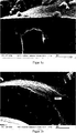
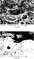
Das Substrat war IN738 mit einem Durchmesser von 30 mm und einer Dicke von 3 mm und wurde zunächst mit 150 μm vakuumplasmagespritztem NiCoCrAlY-Bondcoat versehen. Sodann wurden 300 μm YSZ atmosphärisch plasmagespritzt. Die in Teilbild a gezeigte Schicht blieb unbehandelt. Die in Teilbild b gezeigte Schicht wurde erfindungsgemäß vergütet. Dabei wurde Al2O3 als Vergütungsmaterial eingesetzt und es wurden 150 Beschichtungszyklen durchlaufen. The substrate was IN738 with a diameter of 30 mm and a thickness of 3 mm and was first provided with 150 μm vacuum plasma sprayed NiCoCrAlY bondcoat. Then 300 μm YSZ were plasma sprayed atmospherically. The layer shown in panel a remained untreated. The layer shown in panel b was tempered according to the invention. Al 2 O 3 was used as the tempering material and 150 coating cycles were carried out.
Die Schichten wurden jeweils mittleren Oberflächentemperaturen von 1370°C ausgesetzt. Das Substrat unter der in Teilbild a gezeigten Schicht hatte eine mittlere Temperatur von 1044°C; das Substrat unter der in Teilbild b gezeigten Schicht hatte eine mittlere Temperatur von 1049°C.The layers were each exposed to average surface temperatures of 1370 ° C. The substrate under the layer shown in panel a had an average temperature of 1044 ° C; the substrate under the layer shown in panel b had an average temperature of 1049 ° C.
Zur Überprüfung der Haltbarkeit wurden die Schichten in einem Thermozyklierversuch pro Zyklus jeweils 5 min aufgeheizt und 2 min gekühlt. Die in Teilbild a gezeigte Schicht durchlief 264 Zyklen, die in Teilbild b gezeigte Schicht durchlief 271 Zyklen bevor es zum Versagen der Schichten kam.In order to check the durability, the layers were heated in a thermocycling test per cycle for 5 min each and cooled for 2 min. The layer shown in panel a passed through 264 cycles, the layer shown in panel b went through 271 cycles before the layers failed.
Einige Details zu den Herstellungsbedingungen verschiedenartiger Schichten über CVD Verfahren sind im Folgenden dargestellt. Auch andere Beschichtungswerkstoffe können über die Wahl geeigneter Precursoren genutzt werden.Some details on the production conditions of different layers via CVD methods are shown below. Other coating materials can be used by choosing suitable precursors.
A. YSZ mit ALDA. YSZ with ALD
Hier wird meist vollstabilisiertes YSZ für SOFCs für verschiedene Anwendungen in der Elektronik (z. B. Barriereschichten, Speicherelemente) eingesetzt. Auch reines ZrO2 lässt sich bei Herstellung nur mit Zr Precursoren herstellen.Fully stabilized YSZ for SOFCs is usually used here for various applications in electronics (eg barrier layers, memory elements). Pure ZrO 2 can also be produced only with Zr Precursors.
Geeignete Precursoren:Suitable precursors:
- PA: ZrCl4 und Yttrium tris (2,2,6,6-tetramethyl-3,5-heptanedionate) Y(OCC(CH3)3CHCOC(CH3)3)3 PA: ZrCl 4 and yttrium tris (2,2,6,6-tetramethyl-3,5-heptanedionate) Y (OCC (CH 3 ) 3 CHCOC (CH 3 ) 3 ) 3
- PB: H2OPB: H 2 O
- PA: Zirconium tetrakis(2,2,6,6-tetramethyl-3,5-heptanedionate) Zr(OCC(CH3)3CHCOC(CH3)3)4 oder Zirconium acetylacetonate Zr(C6H7O2)4 oder Zirconium bis(cyclopentadienyl)dimethyl (C5H5)2Zr(CH3)2 und Yttrium tris(2,2,6,6-tetramethyl-3,5-heptanedionate) Y(OCC(CH3)3CHCOC(CH3)3)3 PA: zirconium tetrakis (2,2,6,6-tetramethyl-3,5-heptanedionate) Zr (OCC (CH 3 ) 3 CHCOC (CH 3 ) 3 ) 4 or zirconium acetylacetonate Zr (C 6 H 7 O 2 ) 4 or zirconium bis (cyclopentadienyl) dimethyl (C 5 H 5 ) 2 Zr (CH 3 ) 2 and yttrium tris (2,2,6,6-tetramethyl-3,5-heptanedionate) Y (OCC (CH 3 ) 3 CHCOC ( CH 3 ) 3 ) 3
- PB: O3 PB: O 3
- PA: Zirconium tetrakis(dimethylamino)Zr[N(CH3)2]4 und Yttrium tris(butylcyclopentadienyl)Y(C5H4CH2(CH2)2CH3)3 PA: zirconium tetrakis (dimethylamino) Zr [N (CH 3 ) 2 ] 4 and yttrium tris (butylcyclopentadienyl) Y (C 5 H 4 CH 2 (CH 2 ) 2 CH 3 ) 3
- PB: H2OPB: H 2 O
- PA: ZrCl4 und Yttrium tris(butylcyclopentadienyl)Y(C5H4CH2(CH2)2CH3)3 PA: ZrCl 4 and yttrium tris (butylcyclopentadienyl) Y (C 5 H 4 CH 2 (CH 2 ) 2 CH 3 ) 3
- PB: H2OPB: H 2 O
B: Perowskite ABO3 mit MOCVD (engl.: metal organic chemical vapour deposition)B: Perovskite ABO 3 with MOCVD (English: metal organic chemical vapor deposition)
- Zum Beispiel Manganite (z. B. La1-xSrxMnO3), Ferrate (z. B. La1-xSrxFe1-y(Co,Ni)yO3), Gallate (z. B. La1-xSrxGa1-y(Co,Ni,Fe)yO3), Cobaltite (z. B. La1-xSrxCoO3) oder Titanate (z. B. PbTiO3, SrTiO3, BaTiO3) geeignete Precursoren: Metal β-diketonate, z. B. Zr(TMHD)4, Y(TMHD)3, TMHD = C11H19O2 (Tetramethyl heptandionat) und Titan(IV)isopropoxid Ti(C3H7O)4 For example, manganites (e.g., La 1-x Sr x MnO 3 ), ferrates (e.g., La 1-x Sr x Fe 1-y (Co, Ni) y O 3 ), gallates (e.g. La 1-x Sr x Ga 1-y (Co, Ni, Fe) y O 3 ), cobaltites (eg La 1-x Sr x CoO 3 ) or titanates (eg PbTiO 3 , SrTiO 3 , BaTiO 3 ) suitable precursors: metal β-diketonates, z. Zr (TMHD) 4 , Y (TMHD) 3 , TMHD = C 11 H 19 O 2 (tetramethylheptanedionate) and titanium (IV) isopropoxide Ti (C 3 H 7 O) 4
C: Pyrochlore A2B2O7 mit MOCVD (engl.: metal organic chemical vapour deposition)C: Pyrochlore A 2 B 2 O 7 with MOCVD (English: metal organic chemical vapor deposition)
- zum Beipsiel La2Zr2O7 geeignete Precursoren: Metal β-diketonate: Lanthanum Acetylacetonat Hydrat La(C5H7O2)3 und Zirconium(IV) Acetylacetonat Zr(C6H7O2)4 in Propansäure (CN3-CH2-COOH) Bi2Ti2O7 (z. B. für Hochfrequenz-Kondensatoren) geeignete Precursoren: Trimethyl Bismuth Bi(CH3)3 und Titan(IV)isopropoxid Ti(OC3H7)4 mit O2 for Beipsiel La 2 Zr 2 O 7 suitable precursors: Metal β-diketonates: Lanthanum acetylacetonate hydrate La (C 5 H 7 O 2) 3, and zirconium (IV) acetylacetonate Zr (C 6 H 7 O 2) 4 (in propanoic CN 3 -CH 2 -COOH) Bi 2 Ti 2 O 7 (eg for high-frequency capacitors) suitable precursors: trimethyl bismuth Bi (CH 3 ) 3 and titanium (IV) isopropoxide Ti (OC 3 H 7 ) 4 with O 2
Damit sich diese Precursoren für Perowskite und Pyrochlore auch für einen ALD Prozess nutzbar machen lassen, ist es erforderlich, dass sich die Schichtbildungsreaktionen in eine Folge von zwei Teilstufen aufspalten lassen, so dass jeweils eine vollständige Oberflächensättigung durch je einen Precursor sowie die Bildung geeigneter Oberflächengruppen zur Chemisorption des anderen Precursors erreicht werden.In order to make these precursors for perovskites and pyrochlors usable for an ALD process as well, it is necessary that the layer formation reactions can be split into a sequence of two partial stages, so that in each case a complete surface saturation by a respective precursor and the formation of suitable surface groups Chemisorption of the other precursor can be achieved.
ZITATE ENTHALTEN IN DER BESCHREIBUNG QUOTES INCLUDE IN THE DESCRIPTION
Diese Liste der vom Anmelder aufgeführten Dokumente wurde automatisiert erzeugt und ist ausschließlich zur besseren Information des Lesers aufgenommen. Die Liste ist nicht Bestandteil der deutschen Patent- bzw. Gebrauchsmusteranmeldung. Das DPMA übernimmt keinerlei Haftung für etwaige Fehler oder Auslassungen.This list of the documents listed by the applicant has been generated automatically and is included solely for the better information of the reader. The list is not part of the German patent or utility model application. The DPMA assumes no liability for any errors or omissions.
Zitierte PatentliteraturCited patent literature
- DE 10200803 A1 [0004, 0004] DE 10200803 A1 [0004, 0004]
Claims (24)
Priority Applications (6)
| Application Number | Priority Date | Filing Date | Title |
|---|---|---|---|
| DE201010015470 DE102010015470A1 (en) | 2010-04-16 | 2010-04-16 | Process for the internal coating of functional layers with a tempering material |
| PCT/DE2011/000370 WO2011127896A1 (en) | 2010-04-16 | 2011-04-05 | Process for internally coating functional layers with a through-hardened material |
| CN2011800193259A CN102844461A (en) | 2010-04-16 | 2011-04-05 | Process for internally coating functional layers with through-hardened material |
| EP11724528A EP2558611A1 (en) | 2010-04-16 | 2011-04-05 | Process for internally coating functional layers with a through-hardened material |
| US13/640,401 US20130196141A1 (en) | 2010-04-16 | 2011-04-05 | Process for internally coating functional layers with a through-hardened material |
| JP2013504118A JP2013525599A (en) | 2010-04-16 | 2011-04-05 | Method for internal coating of functional layer with modified material |
Applications Claiming Priority (1)
| Application Number | Priority Date | Filing Date | Title |
|---|---|---|---|
| DE201010015470 DE102010015470A1 (en) | 2010-04-16 | 2010-04-16 | Process for the internal coating of functional layers with a tempering material |
Publications (1)
| Publication Number | Publication Date |
|---|---|
| DE102010015470A1 true DE102010015470A1 (en) | 2011-10-20 |
Family
ID=44202162
Family Applications (1)
| Application Number | Title | Priority Date | Filing Date |
|---|---|---|---|
| DE201010015470 Withdrawn DE102010015470A1 (en) | 2010-04-16 | 2010-04-16 | Process for the internal coating of functional layers with a tempering material |
Country Status (6)
| Country | Link |
|---|---|
| US (1) | US20130196141A1 (en) |
| EP (1) | EP2558611A1 (en) |
| JP (1) | JP2013525599A (en) |
| CN (1) | CN102844461A (en) |
| DE (1) | DE102010015470A1 (en) |
| WO (1) | WO2011127896A1 (en) |
Cited By (1)
| Publication number | Priority date | Publication date | Assignee | Title |
|---|---|---|---|---|
| CN113529075A (en) * | 2020-04-20 | 2021-10-22 | 厦门大学 | Liquid metal composite porous membrane and preparation method and application thereof |
Families Citing this family (9)
| Publication number | Priority date | Publication date | Assignee | Title |
|---|---|---|---|---|
| US9290836B2 (en) * | 2012-08-17 | 2016-03-22 | General Electric Company | Crack-resistant environmental barrier coatings |
| US11326253B2 (en) * | 2016-04-27 | 2022-05-10 | Applied Materials, Inc. | Atomic layer deposition of protective coatings for semiconductor process chamber components |
| US10975469B2 (en) * | 2017-03-17 | 2021-04-13 | Applied Materials, Inc. | Plasma resistant coating of porous body by atomic layer deposition |
| US11473197B2 (en) | 2018-03-16 | 2022-10-18 | Raytheon Technologies Corporation | HPC and HPT disks coated by atomic layer deposition |
| US10443126B1 (en) * | 2018-04-06 | 2019-10-15 | Applied Materials, Inc. | Zone-controlled rare-earth oxide ALD and CVD coatings |
| WO2019209401A1 (en) * | 2018-04-27 | 2019-10-31 | Applied Materials, Inc. | Protection of components from corrosion |
| US11053855B2 (en) | 2019-06-06 | 2021-07-06 | Raytheon Technologies Corporation | Reflective coating and coating process therefor |
| EP3754049A1 (en) * | 2019-06-21 | 2020-12-23 | Raytheon Technologies Corporation | Reactive thermal barrier coating |
| FR3114588B1 (en) * | 2020-09-29 | 2023-08-11 | Safran Ceram | Process for manufacturing an environmental barrier |
Citations (7)
| Publication number | Priority date | Publication date | Assignee | Title |
|---|---|---|---|---|
| EP0852223A1 (en) * | 1996-12-04 | 1998-07-08 | European Atomic Energy Community (Euratom) | Method of sealing open-pore ceramic coatings, in particular thermal barriers |
| US20030059633A1 (en) * | 2001-09-21 | 2003-03-27 | Ackerman John Frederick | Article protected by thermal barrier coating having a sintering inhibitor, and its fabrication |
| DE10200803A1 (en) | 2002-01-11 | 2003-07-31 | Forschungszentrum Juelich Gmbh | Production of a ceramic material for a thermal insulation layer and a thermal insulation layer containing the material |
| US20050158590A1 (en) * | 2004-01-16 | 2005-07-21 | Honeywell International Inc. | Atomic layer deposition for turbine components |
| WO2006102568A2 (en) * | 2005-03-22 | 2006-09-28 | Burchill Stuart G Jr | Highly porous coated fine particles, composition, and method of production |
| US20070141255A1 (en) * | 2005-12-21 | 2007-06-21 | Bilal Zuberi | Method and apparatus for strengthening a porous substrate |
| WO2010139855A1 (en) * | 2009-06-05 | 2010-12-09 | Beneq Oy | Protective coating, method for protecting a substrate and use for the same |
Family Cites Families (3)
| Publication number | Priority date | Publication date | Assignee | Title |
|---|---|---|---|---|
| US20050202168A1 (en) * | 2002-08-16 | 2005-09-15 | General Electric Company | Thermally-stabilized thermal barrier coating and process therefor |
| US20050287826A1 (en) * | 2004-06-29 | 2005-12-29 | Abell Thomas J | Method of sealing low-k dielectrics and devices made thereby |
| US7678712B2 (en) * | 2005-03-22 | 2010-03-16 | Honeywell International, Inc. | Vapor phase treatment of dielectric materials |
-
2010
- 2010-04-16 DE DE201010015470 patent/DE102010015470A1/en not_active Withdrawn
-
2011
- 2011-04-05 US US13/640,401 patent/US20130196141A1/en not_active Abandoned
- 2011-04-05 JP JP2013504118A patent/JP2013525599A/en not_active Withdrawn
- 2011-04-05 CN CN2011800193259A patent/CN102844461A/en active Pending
- 2011-04-05 EP EP11724528A patent/EP2558611A1/en not_active Withdrawn
- 2011-04-05 WO PCT/DE2011/000370 patent/WO2011127896A1/en active Application Filing
Patent Citations (7)
| Publication number | Priority date | Publication date | Assignee | Title |
|---|---|---|---|---|
| EP0852223A1 (en) * | 1996-12-04 | 1998-07-08 | European Atomic Energy Community (Euratom) | Method of sealing open-pore ceramic coatings, in particular thermal barriers |
| US20030059633A1 (en) * | 2001-09-21 | 2003-03-27 | Ackerman John Frederick | Article protected by thermal barrier coating having a sintering inhibitor, and its fabrication |
| DE10200803A1 (en) | 2002-01-11 | 2003-07-31 | Forschungszentrum Juelich Gmbh | Production of a ceramic material for a thermal insulation layer and a thermal insulation layer containing the material |
| US20050158590A1 (en) * | 2004-01-16 | 2005-07-21 | Honeywell International Inc. | Atomic layer deposition for turbine components |
| WO2006102568A2 (en) * | 2005-03-22 | 2006-09-28 | Burchill Stuart G Jr | Highly porous coated fine particles, composition, and method of production |
| US20070141255A1 (en) * | 2005-12-21 | 2007-06-21 | Bilal Zuberi | Method and apparatus for strengthening a porous substrate |
| WO2010139855A1 (en) * | 2009-06-05 | 2010-12-09 | Beneq Oy | Protective coating, method for protecting a substrate and use for the same |
Cited By (1)
| Publication number | Priority date | Publication date | Assignee | Title |
|---|---|---|---|---|
| CN113529075A (en) * | 2020-04-20 | 2021-10-22 | 厦门大学 | Liquid metal composite porous membrane and preparation method and application thereof |
Also Published As
| Publication number | Publication date |
|---|---|
| EP2558611A1 (en) | 2013-02-20 |
| US20130196141A1 (en) | 2013-08-01 |
| CN102844461A (en) | 2012-12-26 |
| JP2013525599A (en) | 2013-06-20 |
| WO2011127896A1 (en) | 2011-10-20 |
Similar Documents
| Publication | Publication Date | Title |
|---|---|---|
| DE102010015470A1 (en) | Process for the internal coating of functional layers with a tempering material | |
| DE60103904T2 (en) | HEAT INSULATION LAYER WITH HIGH PHASE STABILITY | |
| DE4429825C1 (en) | Coated component made of quartz glass | |
| DE69916149T2 (en) | Improved aluminide diffusion bonding layer for thermal barrier systems and methods therefor | |
| DE10056617C2 (en) | Material for temperature-stressed substrates | |
| DE60026973T2 (en) | HEAT INSULATION LAYER WITH SINTER RESISTANCE | |
| EP1386017B1 (en) | Heat insulating layer based on la2 zr2 o7 for high temperatures | |
| EP2251457B1 (en) | NiCoCrAl- or CoCrAl-coating with Re | |
| DE112008003502T5 (en) | Method for improving resistance to CMAS infiltration | |
| EP3472366B1 (en) | Self-healing heat damping layers and method for producing same | |
| DE60021722T2 (en) | THERMAL LAYER | |
| EP1463845B1 (en) | Production of a ceramic material for a heat-insulating layer and heat-insulating layer containing said material | |
| DE102004053959B4 (en) | Ceramic material and its use, as well as methods for producing coatings with the ceramic material | |
| EP0890559B1 (en) | Process for coating of oxide fibers with metal aluminates for the manufacture of composites having failure tolerance and high temperature and oxidation resistance | |
| DE102018201771A1 (en) | Aqueous suspension containing metal carbide particles | |
| DE102007043791A1 (en) | Process for the preparation of a thermal barrier coating and thermal barrier coating | |
| WO2008000247A1 (en) | Method for the corrosion protection of ceramic surfaces, bodies comprising such ceramic surfaces and use thereof | |
| AT521011B1 (en) | Component with a two-layer, oxidic protective layer | |
| DE102010055659A1 (en) | Method for depositing dielectric layers in vacuum and use of the method | |
| DE102015200076A1 (en) | Thermal barrier coating system with ceramic porous basecoat | |
| WO2003097901A1 (en) | Heat insulating layer | |
| DE602004001193T2 (en) | A method of making a coated superalloy substrate stabilized against the formation of a secondary reaction zone | |
| DE102016200294A1 (en) | Coating system for gas turbines | |
| EP1144720B1 (en) | Method for producing a thermal barrier coating | |
| DE4028173A1 (en) | CERAMIC MATERIAL AND INSULATION COVER MADE THEREOF |
Legal Events
| Date | Code | Title | Description |
|---|---|---|---|
| R120 | Application withdrawn or ip right abandoned |