CN115207544A - Vibration reduction protection device for new energy automobile battery - Google Patents
Vibration reduction protection device for new energy automobile battery Download PDFInfo
- Publication number
- CN115207544A CN115207544A CN202210856294.2A CN202210856294A CN115207544A CN 115207544 A CN115207544 A CN 115207544A CN 202210856294 A CN202210856294 A CN 202210856294A CN 115207544 A CN115207544 A CN 115207544A
- Authority
- CN
- China
- Prior art keywords
- shell
- negative poisson
- poisson ratio
- walled tube
- new energy
- Prior art date
- Legal status (The legal status is an assumption and is not a legal conclusion. Google has not performed a legal analysis and makes no representation as to the accuracy of the status listed.)
- Pending
Links
- 230000017525 heat dissipation Effects 0.000 claims abstract description 35
- 238000013016 damping Methods 0.000 claims abstract description 23
- 238000010521 absorption reaction Methods 0.000 claims abstract description 17
- 238000005192 partition Methods 0.000 claims abstract description 10
- 239000006260 foam Substances 0.000 claims abstract description 8
- 229910052751 metal Inorganic materials 0.000 claims description 22
- 239000002184 metal Substances 0.000 claims description 22
- 230000001681 protective effect Effects 0.000 claims description 13
- 230000035939 shock Effects 0.000 claims description 13
- 239000006096 absorbing agent Substances 0.000 claims description 12
- VYPSYNLAJGMNEJ-UHFFFAOYSA-N Silicium dioxide Chemical compound O=[Si]=O VYPSYNLAJGMNEJ-UHFFFAOYSA-N 0.000 claims description 5
- 239000000741 silica gel Substances 0.000 claims description 5
- 229910002027 silica gel Inorganic materials 0.000 claims description 5
- 230000001012 protector Effects 0.000 claims 1
- 230000000694 effects Effects 0.000 abstract description 11
- 239000003638 chemical reducing agent Substances 0.000 abstract description 2
- 230000003139 buffering effect Effects 0.000 description 4
- 239000000463 material Substances 0.000 description 4
- 238000003466 welding Methods 0.000 description 3
- RTZKZFJDLAIYFH-UHFFFAOYSA-N Diethyl ether Chemical compound CCOCC RTZKZFJDLAIYFH-UHFFFAOYSA-N 0.000 description 2
- WHXSMMKQMYFTQS-UHFFFAOYSA-N Lithium Chemical compound [Li] WHXSMMKQMYFTQS-UHFFFAOYSA-N 0.000 description 2
- XUIMIQQOPSSXEZ-UHFFFAOYSA-N Silicon Chemical compound [Si] XUIMIQQOPSSXEZ-UHFFFAOYSA-N 0.000 description 2
- 229910052744 lithium Inorganic materials 0.000 description 2
- 229920001296 polysiloxane Polymers 0.000 description 2
- 229910052710 silicon Inorganic materials 0.000 description 2
- 239000010703 silicon Substances 0.000 description 2
- LFQSCWFLJHTTHZ-UHFFFAOYSA-N Ethanol Chemical compound CCO LFQSCWFLJHTTHZ-UHFFFAOYSA-N 0.000 description 1
- UFHFLCQGNIYNRP-UHFFFAOYSA-N Hydrogen Chemical compound [H][H] UFHFLCQGNIYNRP-UHFFFAOYSA-N 0.000 description 1
- 229910052782 aluminium Inorganic materials 0.000 description 1
- XAGFODPZIPBFFR-UHFFFAOYSA-N aluminium Chemical compound [Al] XAGFODPZIPBFFR-UHFFFAOYSA-N 0.000 description 1
- 230000009286 beneficial effect Effects 0.000 description 1
- 230000007547 defect Effects 0.000 description 1
- 230000005611 electricity Effects 0.000 description 1
- 238000001125 extrusion Methods 0.000 description 1
- 239000000446 fuel Substances 0.000 description 1
- 239000007789 gas Substances 0.000 description 1
- 239000001257 hydrogen Substances 0.000 description 1
- 229910052739 hydrogen Inorganic materials 0.000 description 1
- 239000003208 petroleum Substances 0.000 description 1
- 230000007704 transition Effects 0.000 description 1
Images


Classifications
-
- H—ELECTRICITY
- H01—ELECTRIC ELEMENTS
- H01M—PROCESSES OR MEANS, e.g. BATTERIES, FOR THE DIRECT CONVERSION OF CHEMICAL ENERGY INTO ELECTRICAL ENERGY
- H01M50/00—Constructional details or processes of manufacture of the non-active parts of electrochemical cells other than fuel cells, e.g. hybrid cells
- H01M50/20—Mountings; Secondary casings or frames; Racks, modules or packs; Suspension devices; Shock absorbers; Transport or carrying devices; Holders
- H01M50/233—Mountings; Secondary casings or frames; Racks, modules or packs; Suspension devices; Shock absorbers; Transport or carrying devices; Holders characterised by physical properties of casings or racks, e.g. dimensions
- H01M50/242—Mountings; Secondary casings or frames; Racks, modules or packs; Suspension devices; Shock absorbers; Transport or carrying devices; Holders characterised by physical properties of casings or racks, e.g. dimensions adapted for protecting batteries against vibrations, collision impact or swelling
-
- H—ELECTRICITY
- H01—ELECTRIC ELEMENTS
- H01M—PROCESSES OR MEANS, e.g. BATTERIES, FOR THE DIRECT CONVERSION OF CHEMICAL ENERGY INTO ELECTRICAL ENERGY
- H01M10/00—Secondary cells; Manufacture thereof
- H01M10/60—Heating or cooling; Temperature control
- H01M10/61—Types of temperature control
- H01M10/613—Cooling or keeping cold
-
- H—ELECTRICITY
- H01—ELECTRIC ELEMENTS
- H01M—PROCESSES OR MEANS, e.g. BATTERIES, FOR THE DIRECT CONVERSION OF CHEMICAL ENERGY INTO ELECTRICAL ENERGY
- H01M10/00—Secondary cells; Manufacture thereof
- H01M10/60—Heating or cooling; Temperature control
- H01M10/62—Heating or cooling; Temperature control specially adapted for specific applications
- H01M10/625—Vehicles
-
- H—ELECTRICITY
- H01—ELECTRIC ELEMENTS
- H01M—PROCESSES OR MEANS, e.g. BATTERIES, FOR THE DIRECT CONVERSION OF CHEMICAL ENERGY INTO ELECTRICAL ENERGY
- H01M10/00—Secondary cells; Manufacture thereof
- H01M10/60—Heating or cooling; Temperature control
- H01M10/65—Means for temperature control structurally associated with the cells
- H01M10/653—Means for temperature control structurally associated with the cells characterised by electrically insulating or thermally conductive materials
-
- H—ELECTRICITY
- H01—ELECTRIC ELEMENTS
- H01M—PROCESSES OR MEANS, e.g. BATTERIES, FOR THE DIRECT CONVERSION OF CHEMICAL ENERGY INTO ELECTRICAL ENERGY
- H01M10/00—Secondary cells; Manufacture thereof
- H01M10/60—Heating or cooling; Temperature control
- H01M10/65—Means for temperature control structurally associated with the cells
- H01M10/655—Solid structures for heat exchange or heat conduction
- H01M10/6554—Rods or plates
-
- H—ELECTRICITY
- H01—ELECTRIC ELEMENTS
- H01M—PROCESSES OR MEANS, e.g. BATTERIES, FOR THE DIRECT CONVERSION OF CHEMICAL ENERGY INTO ELECTRICAL ENERGY
- H01M10/00—Secondary cells; Manufacture thereof
- H01M10/60—Heating or cooling; Temperature control
- H01M10/65—Means for temperature control structurally associated with the cells
- H01M10/656—Means for temperature control structurally associated with the cells characterised by the type of heat-exchange fluid
- H01M10/6561—Gases
- H01M10/6563—Gases with forced flow, e.g. by blowers
-
- H—ELECTRICITY
- H01—ELECTRIC ELEMENTS
- H01M—PROCESSES OR MEANS, e.g. BATTERIES, FOR THE DIRECT CONVERSION OF CHEMICAL ENERGY INTO ELECTRICAL ENERGY
- H01M50/00—Constructional details or processes of manufacture of the non-active parts of electrochemical cells other than fuel cells, e.g. hybrid cells
- H01M50/20—Mountings; Secondary casings or frames; Racks, modules or packs; Suspension devices; Shock absorbers; Transport or carrying devices; Holders
- H01M50/249—Mountings; Secondary casings or frames; Racks, modules or packs; Suspension devices; Shock absorbers; Transport or carrying devices; Holders specially adapted for aircraft or vehicles, e.g. cars or trains
-
- Y—GENERAL TAGGING OF NEW TECHNOLOGICAL DEVELOPMENTS; GENERAL TAGGING OF CROSS-SECTIONAL TECHNOLOGIES SPANNING OVER SEVERAL SECTIONS OF THE IPC; TECHNICAL SUBJECTS COVERED BY FORMER USPC CROSS-REFERENCE ART COLLECTIONS [XRACs] AND DIGESTS
- Y02—TECHNOLOGIES OR APPLICATIONS FOR MITIGATION OR ADAPTATION AGAINST CLIMATE CHANGE
- Y02E—REDUCTION OF GREENHOUSE GAS [GHG] EMISSIONS, RELATED TO ENERGY GENERATION, TRANSMISSION OR DISTRIBUTION
- Y02E60/00—Enabling technologies; Technologies with a potential or indirect contribution to GHG emissions mitigation
- Y02E60/10—Energy storage using batteries
Abstract
The invention discloses a vibration reduction protection device of a new energy automobile battery, which comprises a shell and a battery module, wherein partition plates are arranged in the shell at intervals along the circumferential direction of the battery module, are connected with the battery module through a vibration reducer and are connected with the shell through a negative Poisson ratio energy absorption piece; the negative Poisson ratio energy absorption part comprises a first negative Poisson ratio thin-walled tube, a second negative Poisson ratio thin-walled tube, a honeycomb layer and a foam layer, wherein the second negative Poisson ratio thin-walled tube is nested in the first negative Poisson ratio thin-walled tube, the honeycomb layer is filled between the first negative Poisson ratio thin-walled tube and the second negative Poisson ratio thin-walled tube, and the foam layer is filled in the second negative Poisson ratio thin-walled tube; a heat dissipation device is arranged in the shell, and a supporting vibration damping device is arranged at the bottom of the shell. The invention can effectively absorb the vibration impact energy, realize the vibration damping effect and directly play a role in protecting the battery module; can cool down the battery effectively, play fine radiating action.
Description
Technical Field
The invention belongs to a vibration damping device, and particularly relates to a vibration damping protection device for a new energy automobile battery.
Background
Due to increasingly scarce petroleum resources and increasingly exhausted global environment, new energy automobiles are increasingly popular with people. With the development of new energy vehicles, the types of the new energy vehicles are various, and the new energy vehicles mainly comprise hybrid electric vehicles, pure electric vehicles, fuel cell vehicles, hydrogen engine vehicles, gas vehicles and alcohol ether vehicles. At present, new energy automobiles use electricity as a main energy source, and the safety of batteries of the new energy automobiles is particularly important. The new energy automobile battery has higher requirements on impact resistance, vibration reduction and heat dissipation so as to protect the battery and enable the power to be continuously and stably output.
However, the conventional protection of the new energy automobile battery is usually to arrange a protection shell outside the new energy automobile battery, so that the battery cannot be damaged when collision or extrusion occurs, and the battery is difficult to be well protected, thereby causing the battery to work abnormally. Although the protective shell has certain heat dissipation and energy absorption effects, the heat dissipation and energy absorption buffering effects of the battery box are not ideal and need to be further improved.
Chinese patent No. 2019216411611.9 discloses an electric motor car lithium cell with protection architecture, gives aluminum plate and fin through heat conduction silica gel and heat conduction frame with the heat transfer that the battery produced, and the fan can accelerate the flow of air, promotes the heat dissipation of electric motor car lithium cell. However, the direction of the buffer vibration reduction is single, only longitudinal buffer vibration reduction can be realized, and only one buffer vibration reduction is realized. Meanwhile, the air around the heat sink is not smooth in heat dissipation, resulting in unsatisfactory heat dissipation.
The Chinese patent with the application number of 201811558365.0 discloses a shock-resistant energy-absorbing battery box with high-efficiency heat dissipation, and the inside of the box body can effectively absorb impact energy transmitted by the box body through a spring between a heat dissipation plate and the box body and a honeycomb sandwich structure of a heat conduction plate, so that the battery module is protected from being influenced in work in many aspects. However, the direction of the buffer vibration reduction is single, only longitudinal buffer vibration reduction can be realized, and only one buffer vibration reduction is realized.
In general, the existing battery has a single buffering and vibration damping direction, and the buffering and vibration damping effect needs to be further improved
Disclosure of Invention
The purpose of the invention is as follows: in order to overcome the defects in the prior art, the invention aims to provide the vibration reduction protection device of the new energy automobile battery, which has multiple energy absorption and vibration reduction effects and a good heat dissipation effect.
The technical scheme is as follows: the vibration reduction protection device for the new energy automobile battery comprises a shell and a battery module, wherein partition plates are arranged in the shell at intervals along the circumferential direction of the battery module, are connected with the battery module through a vibration reducer and are connected with the shell through a negative Poisson ratio energy absorption piece; the negative Poisson ratio energy absorption part comprises a first negative Poisson ratio thin-walled tube, a second negative Poisson ratio thin-walled tube, a honeycomb layer and a foam layer, wherein the second negative Poisson ratio thin-walled tube is nested in the first negative Poisson ratio thin-walled tube, the honeycomb layer is filled between the first negative Poisson ratio thin-walled tube and the second negative Poisson ratio thin-walled tube, and the foam layer is filled in the second negative Poisson ratio thin-walled tube; a heat dissipation device is arranged in the shell, and a supporting vibration damper is arranged at the bottom of the shell.
Further, the shock absorber comprises a first stress rod, a first spring, a protective sleeve and a second stress rod, the first stress rod and the second stress rod are connected in a nested mode and can move freely, the first stress rod is connected with the protective sleeve through the first spring, and the protective sleeve is connected with the second stress rod. The protective sleeve is gourd-shaped. The protective sleeve is made of rubber materials, and the first spring has certain pretightening force. 1-2 rows of gourd-shaped vibration absorbers are placed on each partition plate, and the gourd-shaped vibration absorbers in each row are arranged at equal intervals.
Further, the heat dissipation device comprises a heat conduction silica gel sheet, a heat conduction metal sheet, heat dissipation metal sheets and a fan, wherein the heat dissipation metal sheets which are staggered with each other are arranged in the heat conduction metal sheets, the fan is arranged at the bottom of the heat conduction metal sheets, the heat conduction metal sheets are connected with the partition plate through the heat conduction silica gel sheet, and the fan is connected with the shell through the fixing plate.
Furthermore, the bottom of the shell is provided with a groove connected with the supporting vibration damper for installing and fixing screw holes.
Further, the supporting and vibration damping device comprises a supporting frame, a gasket and a second spring, the gasket and the supporting frame are all nested in the groove, and the supporting frame is connected with the shell through the second spring. The support frame is I-shaped. The second spring is installed between the top of the support frame and the inner wall of the shell through a screw. The gasket is made of rubber material.
Furthermore, the bottom of the shell is provided with honeycomb holes for absorbing energy and damping vibration. An air outlet is arranged on the shell.
The working principle is as follows: the supporting vibration damper forms a first heavy energy absorption vibration damping effect on external impact and vibration, the honeycomb holes at the bottom of the shell form a second heavy energy absorption vibration damping effect on the impact and the vibration received by the shell, the negative Poisson's ratio energy absorption piece arranged in the shell forms a third heavy energy absorption vibration damping effect on the impact and the vibration transmitted by the shell, and the gourd-shaped vibration damper arranged in the shell finally absorbs the rest impact and vibration. Meanwhile, the heat generated by the battery during working is efficiently dissipated by the heat dissipation device, the heat conducting silicon sheet in the heat dissipation device transfers the heat to the heat conducting metal sheet, the heat conducting metal sheet transfers the heat to the heat dissipation fins for heat dissipation, the fan accelerates the air flow around the heat dissipation fins, and the air inlet and the air outlet are vertically opposite to each other to further accelerate the air flow speed.
Has the beneficial effects that: compared with the prior art, the invention has the following remarkable characteristics:
1. the automobile battery cushion can perform multiple buffering and vibration reduction on external impact, and can buffer and absorb impacts in multiple directions, such as longitudinal impact and axial impact, so that the safety performance of the automobile battery is greatly improved;
2. the heat dissipation metal sheets which are arranged in the heat dissipation device in a staggered mode can effectively dissipate heat generated by the battery, and the fans, the air inlets and the air outlets are arranged right opposite to each other, so that air flowing around the heat dissipation fins can be accelerated, and efficient heat dissipation of the automobile battery is achieved.
Drawings
FIG. 1 is a perspective view of the present invention;
FIG. 2 is a top plan view of the present invention without the lid;
FIG. 3 is an exploded view of the present invention;
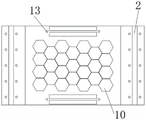
fig. 4 is a bottom sectional view of the housing 1 of the present invention;
FIG. 5 is a schematic structural view of the shock absorber 4 of the present invention;
FIG. 6 is a schematic structural view of the negative Poisson's ratio energy absorbing member 5 of the present invention;
FIG. 7 is an enlarged view of a portion of the invention at A;
FIG. 8 is a schematic structural view of a thermally conductive metal sheet 602 according to the present invention;
FIG. 9 is a left side view of the present invention;
fig. 10 is a partially enlarged view of the present invention B.
Detailed Description
Referring to fig. 1-2, a housing 1 of the vibration damping protection device for the new energy automobile battery is composed of a box cover and a rectangular box body which are in transition fit. The partition plates 3 are arranged in the housing 1 at intervals in the circumferential direction of the battery module 2, the housing 1 is axisymmetric, and the partition plates 3 include short straight plates 302, long straight plates 303, and corner plates 301. One end of each gourd-shaped shock absorber 4 is connected to the inner sides of the inner walls of the short straight plate 302, the long straight plate 303 and the angle plate 301 through welding, the other end of each gourd-shaped shock absorber 4 is in direct contact with the battery module 2, certain pretightening force exists, 1-2 rows of gourd-shaped shock absorbers 4 are placed on each partition plate 3, and the shock absorbers 4 in each row are arranged at equal intervals. The negative poisson's ratio energy-absorbing member 5 is connected between the inner wall of the shell 1 and the outer wall of the diaphragm 3 by welding, and is placed one on each of the long straight plate 303 and the short straight plate 302, and one on each of both side edges of the gusset 301. An air inlet 12 for heat dissipation is formed in the bottom of the shell 1 right below the long straight plate 303, a heat dissipation device 6 is arranged below the air inlet 12, and supporting vibration reduction devices 7 are symmetrically arranged at the bottoms of two sides of the rectangular box body.
As shown in fig. 3, the heat sink 6 includes a heat-conductive silicone sheet 601, a heat-conductive metal sheet 602, a heat-dissipating metal sheet 603, a fan 604, and a fixing plate 605. One side of the heat-conducting silicon sheet 601 is tightly attached to the surface of the battery module 2, the other side is attached to the surface of the heat dissipation device 6, and the other side of the heat dissipation device 6 is connected to the long straight plate 303 through welding. A heat conducting metal sheet 602 is welded between the inner side of the housing 1 and the outer side of the long straight plate 303, a fan 604 is arranged at the bottom of the heat conducting metal sheet 602, and the fan 604 is fixed at the bottom of the housing 1 through a fixing plate 605. The supporting and damping device 7 comprises a supporting frame 701, a gasket 702 and a second spring 703, wherein the gasket 702 is placed in a groove 8 at the bottom of the shell 1, then the I-shaped supporting frame 701 is placed, the second spring 703 is further placed, and finally a screw 9 passes through a screw hole 13 of the groove 8 and penetrates through the second spring 703 to fix the supporting frame 701. The gasket 702 and the support frame 701 are both nested in the groove 8, and the gasket 702 is made of rubber. The top of the housing 1, i.e. both sides of the case cover, has air outlets 11 for heat dissipation.
As shown in fig. 4, the bottom of the shell 1 is provided with honeycomb holes 10 for absorbing energy and damping vibration, grooves 8 for mounting and supporting the damping device 7, and screw holes 13 for mounting and fixing.
Referring to fig. 5, the gourd-shaped shock absorber 4 includes a first force-bearing rod 401, a first spring 402, a protective sleeve 403 and a second force-bearing rod 404, the first force-bearing rod 401 and the second force-bearing rod 404 are nested with a gap therebetween and can freely move up and down, the first spring 402 is disposed between the first force-bearing rod 401 and the second force-bearing rod 404, and then a gourd-shaped protective sleeve 403 is disposed outside the first spring 402. The material of the protective sheath 403 is rubber material.
As shown in fig. 6 to 7, the negative poisson's ratio energy-absorbing member 5 comprises a first negative poisson's ratio thin-walled tube 501, a second negative poisson's ratio thin-walled tube 502, a honeycomb layer 503 and a foam layer 504. The first negative poisson ratio thin-walled tube 501 and the second negative poisson ratio thin-walled tube 502 are different in size, the second thin-walled tube 502 with the smaller negative poisson ratio is placed inside the first thin-walled tube 501 with the larger negative poisson ratio, the honeycomb layer 503 is filled between the first thin-walled tube 501 and the second thin-walled tube 502 with the smaller negative poisson ratio, and the foam layer 504 is filled inside the second thin-walled tube 502 with the negative poisson ratio.
Referring to fig. 8, the heat-conducting metal sheets 602 have heat-dissipating metal sheets 603 arranged in an alternating manner.
As shown in fig. 9-10, each groove 8 has 2 rows of screws 9, each row has 5 screws 9, and 10 screws 9 are used to fix the i-shaped support frame 701 and the gasket 702. The second spring 703 is installed between the support frame 701 and the inner wall of the groove 8 through the screw 9.
When the vibration damping protection device of the new energy automobile battery is subjected to external impact and vibration, the support vibration damping device 7 forms a first re-energy absorption vibration damping effect on the external impact and vibration; the honeycomb holes 10 at the bottom of the shell 1 form a second energy absorption and vibration reduction effect on the impact and vibration on the shell 1; the negative Poisson ratio energy absorption piece 5 arranged inside the shell 1 forms a third energy absorption and vibration reduction effect on the impact and the vibration transmitted by the shell 1; the gourd-shaped damper 4 installed inside the housing 1 finally absorbs the remaining shock and vibration.
In addition, the automobile battery may generate high temperature due to continuous operation, the heat conductive silicone sheet 601 may transfer heat to the heat dissipation device 6, the fan 604 cools the air through the air inlet 12 to the heat dissipation device 6, and the air absorbing heat is discharged from the air outlet 11 on the upper surface of the housing 1.
Therefore, the automobile battery shock absorber can effectively absorb external shock and vibration, can effectively cool the high temperature generated by continuous work of the automobile battery, has very good shock absorption and protection performance and heat dissipation performance, and has a good application prospect.
Claims (10)
1. The utility model provides a damping protector of new energy automobile battery which characterized in that: the battery pack comprises a shell (1) and battery modules (2), wherein partition plates (3) are arranged in the shell (1) at intervals along the circumferential direction of the battery modules (2), the partition plates (3) are connected with the battery modules (2) through vibration absorbers (4), and are connected with the shell through negative Poisson ratio energy-absorbing pieces (5); the negative poisson ratio energy absorption piece (5) comprises a first negative poisson ratio thin-walled tube (501), a second negative poisson ratio thin-walled tube (502), a honeycomb layer (503) and a foam layer (504), the second negative poisson ratio thin-walled tube (502) is nested in the first negative poisson ratio thin-walled tube (501), the honeycomb layer (503) is filled between the first negative poisson ratio thin-walled tube and the second negative poisson ratio thin-walled tube (502), and the foam layer (504) is filled in the second negative poisson ratio thin-walled tube (502); a heat dissipation device (6) is arranged in the shell (1), and a supporting vibration damping device (7) is arranged at the bottom of the shell.
2. The vibration reduction protection device for the new energy automobile battery according to claim 1, characterized in that: the shock absorber (4) comprises a first stress rod (401), a first spring (402), a protective sleeve (403) and a second stress rod (404), wherein the first stress rod (401) and the second stress rod (404) are connected in a nested mode, the first stress rod (401) is connected with the protective sleeve (403) through the first spring (402), and the protective sleeve (403) is connected with the second stress rod (404).
3. The vibration reduction protection device for the new energy automobile battery according to claim 2, characterized in that: the protective sleeve (403) is gourd-shaped.
4. The vibration damping and protecting device for the new energy automobile battery according to claim 1, characterized in that: the heat dissipation device (6) comprises a heat conduction silica gel sheet (601), a heat conduction metal sheet (602), a heat dissipation metal sheet (603) and a fan (604), wherein the heat dissipation metal sheet (603) which is staggered with each other is arranged in the heat conduction metal sheet (602), the fan (604) is arranged at the bottom of the heat conduction metal sheet, the heat conduction metal sheet (602) is connected with the partition plate (3) through the heat conduction silica gel sheet (601), and the fan (604) is connected with the shell (1) through a fixing plate (605).
5. The vibration reduction protection device for the new energy automobile battery according to claim 1, characterized in that: the bottom of the shell (1) is provided with a groove (8) connected with the supporting vibration damper (7).
6. The vibration reduction protection device for the new energy automobile battery according to claim 5, characterized in that: the supporting and vibration damping device (7) comprises a supporting frame (701), a gasket (702) and a second spring (703), the gasket (702) and the supporting frame (701) are both nested in the groove (8), and the supporting frame (701) is connected with the shell (1) through the second spring (703).
7. The vibration reduction protection device for the new energy automobile battery according to claim 6, characterized in that: the support frame is I-shaped.
8. The vibration damping and protecting device for the new energy automobile battery according to claim 6, characterized in that: the second spring (703) passes through the screw (9) and is installed between the top of the support frame (701) and the inner wall of the shell (1).
9. The vibration reduction protection device for the new energy automobile battery according to claim 1, characterized in that: the bottom of the shell (1) is provided with honeycomb holes (10).
10. The vibration reduction protection device for the new energy automobile battery according to claim 1, characterized in that: an air outlet (11) is arranged on the shell (1).
Priority Applications (1)
| Application Number | Priority Date | Filing Date | Title |
|---|---|---|---|
| CN202210856294.2A CN115207544A (en) | 2022-07-20 | 2022-07-20 | Vibration reduction protection device for new energy automobile battery |
Applications Claiming Priority (1)
| Application Number | Priority Date | Filing Date | Title |
|---|---|---|---|
| CN202210856294.2A CN115207544A (en) | 2022-07-20 | 2022-07-20 | Vibration reduction protection device for new energy automobile battery |
Publications (1)
| Publication Number | Publication Date |
|---|---|
| CN115207544A true CN115207544A (en) | 2022-10-18 |
Family
ID=83581840
Family Applications (1)
| Application Number | Title | Priority Date | Filing Date |
|---|---|---|---|
| CN202210856294.2A Pending CN115207544A (en) | 2022-07-20 | 2022-07-20 | Vibration reduction protection device for new energy automobile battery |
Country Status (1)
| Country | Link |
|---|---|
| CN (1) | CN115207544A (en) |
Citations (9)
| Publication number | Priority date | Publication date | Assignee | Title |
|---|---|---|---|---|
| CN106533021A (en) * | 2016-12-19 | 2017-03-22 | 广东技术师范学院 | Lightweight industrial robot motor box body |
| CN109802068A (en) * | 2019-01-28 | 2019-05-24 | 广西艾盛创制科技有限公司 | A kind of resistance to battery pack case structure for hitting puncture resistant |
| CN110077345A (en) * | 2019-04-22 | 2019-08-02 | 南京理工大学 | A kind of negative poisson's ratio car crass energy-absorption box |
| CN210156447U (en) * | 2019-06-25 | 2020-03-17 | 曾浩 | Battery protective housing for heat dissipation antidetonation type new energy automobile |
| WO2020151270A1 (en) * | 2019-01-24 | 2020-07-30 | 柳海强 | Battery shock absorber for new energy automobile |
| CN112599908A (en) * | 2020-12-16 | 2021-04-02 | 西南交通大学 | New energy automobile battery shock attenuation protector |
| CN213242689U (en) * | 2020-11-03 | 2021-05-18 | 辽宁工业大学 | Impact damping battery pack based on negative Poisson ratio material |
| CN214477648U (en) * | 2021-03-30 | 2021-10-22 | 何永江 | Promote heat abstractor of electric automobile battery |
| CN114211774A (en) * | 2021-11-30 | 2022-03-22 | 哈尔滨工程大学 | Composite material corrugated plate-pipe negative Poisson's ratio structure based on hot die pressing molding process and preparation method |
-
2022
- 2022-07-20 CN CN202210856294.2A patent/CN115207544A/en active Pending
Patent Citations (9)
| Publication number | Priority date | Publication date | Assignee | Title |
|---|---|---|---|---|
| CN106533021A (en) * | 2016-12-19 | 2017-03-22 | 广东技术师范学院 | Lightweight industrial robot motor box body |
| WO2020151270A1 (en) * | 2019-01-24 | 2020-07-30 | 柳海强 | Battery shock absorber for new energy automobile |
| CN109802068A (en) * | 2019-01-28 | 2019-05-24 | 广西艾盛创制科技有限公司 | A kind of resistance to battery pack case structure for hitting puncture resistant |
| CN110077345A (en) * | 2019-04-22 | 2019-08-02 | 南京理工大学 | A kind of negative poisson's ratio car crass energy-absorption box |
| CN210156447U (en) * | 2019-06-25 | 2020-03-17 | 曾浩 | Battery protective housing for heat dissipation antidetonation type new energy automobile |
| CN213242689U (en) * | 2020-11-03 | 2021-05-18 | 辽宁工业大学 | Impact damping battery pack based on negative Poisson ratio material |
| CN112599908A (en) * | 2020-12-16 | 2021-04-02 | 西南交通大学 | New energy automobile battery shock attenuation protector |
| CN214477648U (en) * | 2021-03-30 | 2021-10-22 | 何永江 | Promote heat abstractor of electric automobile battery |
| CN114211774A (en) * | 2021-11-30 | 2022-03-22 | 哈尔滨工程大学 | Composite material corrugated plate-pipe negative Poisson's ratio structure based on hot die pressing molding process and preparation method |
Similar Documents
| Publication | Publication Date | Title |
|---|---|---|
| CN107346814B (en) | Battery thermal management system | |
| CN109755429B (en) | High-efficient radiating antidetonation energy-absorbing battery box | |
| JP7262592B2 (en) | battery module | |
| JP5899420B2 (en) | Battery module | |
| CN105742542A (en) | Forced convection power battery heat radiation device | |
| CN110299484B (en) | Power battery pack based on foamed aluminum material and soft package battery | |
| CN213459934U (en) | Shock absorption type connecting device for lithium ion battery module and box body | |
| JP2009099445A (en) | Battery module and battery pack | |
| KR20170014924A (en) | Battery Module of Indirect Cooling | |
| WO2023185325A1 (en) | Thermal management assembly, battery, and electrical device | |
| CN110289377B (en) | Power battery pack based on foamed aluminum material and cylindrical battery | |
| CN112635873A (en) | Heat dissipation mechanism for new energy automobile battery management | |
| CN115207544A (en) | Vibration reduction protection device for new energy automobile battery | |
| CN210607399U (en) | Electric bicycle lithium cell shock attenuation heat dissipation mounting structure | |
| CN115101853B (en) | Cooling device for new energy automobile | |
| JP2010015954A (en) | Energy storage device | |
| CN216250955U (en) | Battery and electric equipment | |
| JP6063342B2 (en) | Assembled battery | |
| CN214698044U (en) | Automobile radiator with water chamber fairing | |
| CN214577344U (en) | Novel water-cooling radiator for car with shock-absorbing function | |
| CN211376773U (en) | Supporting and heat radiating device for vehicle power device | |
| CN110271402B (en) | Power battery pack, energy storage device and electric vehicle | |
| CN219696588U (en) | New energy heavy truck damping battery box | |
| CN218849560U (en) | High continuation of journey bluetooth headset lithium cell | |
| CN212461906U (en) | Novel lithium battery bearing box for ship |
Legal Events
| Date | Code | Title | Description |
|---|---|---|---|
| PB01 | Publication | ||
| PB01 | Publication | ||
| SE01 | Entry into force of request for substantive examination | ||
| SE01 | Entry into force of request for substantive examination |