CN114849480A - High-efficiency membrane element and production process - Google Patents
High-efficiency membrane element and production process Download PDFInfo
- Publication number
- CN114849480A CN114849480A CN202210702040.5A CN202210702040A CN114849480A CN 114849480 A CN114849480 A CN 114849480A CN 202210702040 A CN202210702040 A CN 202210702040A CN 114849480 A CN114849480 A CN 114849480A
- Authority
- CN
- China
- Prior art keywords
- membrane
- water
- water inlet
- unit
- membrane element
- Prior art date
- Legal status (The legal status is an assumption and is not a legal conclusion. Google has not performed a legal analysis and makes no representation as to the accuracy of the status listed.)
- Pending
Links
- 239000012528 membrane Substances 0.000 title claims abstract description 141
- 238000004519 manufacturing process Methods 0.000 title description 14
- XLYOFNOQVPJJNP-UHFFFAOYSA-N water Substances O XLYOFNOQVPJJNP-UHFFFAOYSA-N 0.000 claims abstract description 167
- 239000003292 glue Substances 0.000 claims abstract description 29
- 239000000565 sealant Substances 0.000 claims description 23
- 238000000926 separation method Methods 0.000 claims description 23
- 238000005096 rolling process Methods 0.000 claims description 14
- 238000001471 micro-filtration Methods 0.000 claims description 4
- 238000001728 nano-filtration Methods 0.000 claims description 4
- 238000001223 reverse osmosis Methods 0.000 claims description 4
- 238000005520 cutting process Methods 0.000 claims description 3
- 238000000108 ultra-filtration Methods 0.000 claims description 3
- 238000000034 method Methods 0.000 claims 3
- 238000000746 purification Methods 0.000 abstract description 6
- 238000007789 sealing Methods 0.000 description 6
- 239000000463 material Substances 0.000 description 2
- 230000009286 beneficial effect Effects 0.000 description 1
- 239000011248 coating agent Substances 0.000 description 1
- 238000000576 coating method Methods 0.000 description 1
- 238000010276 construction Methods 0.000 description 1
- 238000007599 discharging Methods 0.000 description 1
- 230000000694 effects Effects 0.000 description 1
- 238000001914 filtration Methods 0.000 description 1
- MPOKJOWFCMDRKP-UHFFFAOYSA-N gold;hydrate Chemical compound O.[Au] MPOKJOWFCMDRKP-UHFFFAOYSA-N 0.000 description 1
- 239000012535 impurity Substances 0.000 description 1
- 239000000126 substance Substances 0.000 description 1
Images


Classifications
-
- B—PERFORMING OPERATIONS; TRANSPORTING
- B01—PHYSICAL OR CHEMICAL PROCESSES OR APPARATUS IN GENERAL
- B01D—SEPARATION
- B01D69/00—Semi-permeable membranes for separation processes or apparatus characterised by their form, structure or properties; Manufacturing processes specially adapted therefor
-
- C—CHEMISTRY; METALLURGY
- C02—TREATMENT OF WATER, WASTE WATER, SEWAGE, OR SLUDGE
- C02F—TREATMENT OF WATER, WASTE WATER, SEWAGE, OR SLUDGE
- C02F1/00—Treatment of water, waste water, or sewage
- C02F1/44—Treatment of water, waste water, or sewage by dialysis, osmosis or reverse osmosis
-
- Y—GENERAL TAGGING OF NEW TECHNOLOGICAL DEVELOPMENTS; GENERAL TAGGING OF CROSS-SECTIONAL TECHNOLOGIES SPANNING OVER SEVERAL SECTIONS OF THE IPC; TECHNICAL SUBJECTS COVERED BY FORMER USPC CROSS-REFERENCE ART COLLECTIONS [XRACs] AND DIGESTS
- Y02—TECHNOLOGIES OR APPLICATIONS FOR MITIGATION OR ADAPTATION AGAINST CLIMATE CHANGE
- Y02A—TECHNOLOGIES FOR ADAPTATION TO CLIMATE CHANGE
- Y02A20/00—Water conservation; Efficient water supply; Efficient water use
- Y02A20/124—Water desalination
- Y02A20/131—Reverse-osmosis
-
- Y—GENERAL TAGGING OF NEW TECHNOLOGICAL DEVELOPMENTS; GENERAL TAGGING OF CROSS-SECTIONAL TECHNOLOGIES SPANNING OVER SEVERAL SECTIONS OF THE IPC; TECHNICAL SUBJECTS COVERED BY FORMER USPC CROSS-REFERENCE ART COLLECTIONS [XRACs] AND DIGESTS
- Y02—TECHNOLOGIES OR APPLICATIONS FOR MITIGATION OR ADAPTATION AGAINST CLIMATE CHANGE
- Y02W—CLIMATE CHANGE MITIGATION TECHNOLOGIES RELATED TO WASTEWATER TREATMENT OR WASTE MANAGEMENT
- Y02W10/00—Technologies for wastewater treatment
- Y02W10/10—Biological treatment of water, waste water, or sewage
Abstract
The invention discloses a high-efficiency membrane element, which comprises a central tube, wherein a cavity is formed in the central tube, and a plurality of through holes communicated with the cavity are formed in the surface of the central tube; the system has at least one membrane page or leaf unit on the surface book of center tube, and membrane page or leaf unit includes the product water graticule mesh that is connected with the center tube, is equipped with the unit of intaking on the product water graticule mesh, and the unit of intaking includes the diaphragm of fifty percent discount, is equipped with the graticule mesh of intaking in the diaphragm of fifty percent discount, is equipped with the sealed glue of U type structure on the unit of intaking. The invention increases the number of flow passages of the membrane element, thereby utilizing the space of the membrane element and improving the efficiency of water purification.
Description
Technical Field
The invention relates to the technical field of water purification, in particular to a high-efficiency membrane element and a production process.
Background
At present, no matter people's production and life or scientific research construction, the requirement on water quality is also higher and higher, and in actual production and life, often need handle water, gets rid of impurity and other harmful substance in the aquatic, traditional water purification mode is generally realized through using the purifier.
In a water purifier, a water purifying effect is generally realized by arranging a membrane element, in the design of common membrane elements on the market, when water flows pass through the membrane element, a water outlet channel of concentrated water generally only has one channel or a channel in a single direction, and the structure of the membrane element is too single, so that the overall water purifying efficiency of the membrane element is reduced, and the water production rate is low, and therefore, a high-efficiency membrane element needs to be designed to solve the problems.
Disclosure of Invention
The invention aims to provide a high-efficiency membrane element and a production process. The invention increases the number of flow passages of the membrane element, fully utilizes the space of the membrane element and improves the efficiency of water purification.
The technical scheme of the invention is as follows: the high-efficiency membrane element comprises a central tube, wherein a cavity is formed in the central tube, and a plurality of through holes communicated with the cavity are formed in the surface of the central tube; the system has at least one membrane page or leaf unit on the surface book of center tube, and membrane page or leaf unit includes the product water graticule mesh that is connected with the center tube, is equipped with the unit of intaking on the product water graticule mesh, and the unit of intaking includes the diaphragm of fifty percent discount, is equipped with the graticule mesh of intaking in the diaphragm of fifty percent discount, is equipped with the sealed glue of U type structure on the unit of intaking.
In the high-efficiency membrane element, the membrane sheet comprises a separation layer and a support layer, and the membrane sheet is symmetrically folded on the separation layer, so that the separation layer faces inwards and the support layer faces outwards; the graticule mesh of intaking sets up between the separating layer of fifty percent discount and contacts.
In the high-efficiency membrane element, the membrane sheets are folded in half along the short edges, the long edges are overlapped with each other, and the rolling direction of the membrane sheet units is parallel to the direction of the folding lines.
In the high efficiency membrane element, the membrane may be one of a microfiltration membrane, an ultrafiltration membrane, a nanofiltration membrane or a reverse osmosis membrane.
In the aforesaid high efficiency film element, sealed glue of U type structure includes the long gluey line that sets up along the folding opening side long limit of the unit of intaking, still includes the short gluey line that sets up along the both sides minor face of the unit of intaking, and the both ends of long gluey line are connected with the end of two short gluey lines respectively and are formed U type structure.
In the above-mentioned high efficiency membrane element, the membrane element further comprises side glue lines extending from the folding position of the water inlet unit to both sides, wherein one side glue line is located between the central tube and the water inlet unit, and the other side glue line is located between the water inlet unit and the tail end of the water producing grid.
In the high efficiency membrane element, the opening direction of the U-shaped structure is opposite to the folded opening direction of the water inlet unit.
In the aforementioned high efficiency membrane element, the sealant is disposed on the surface of the water producing grid, and the sealant line of the sealant is disposed at a position close to the edge of the water inlet unit.
In the above high efficiency membrane element, the membrane element having two end faces is formed by rolling at least one membrane leaf unit on the surface of the central tube, the two end faces are a pure water outlet face and a pure water inlet face respectively, the pure water outlet face is used for discharging pure water, the pure water inlet face is used for feeding water, and concentrated water flows out from the periphery of the membrane element and one end of the central tube.
The production process of the high-efficiency membrane element is carried out according to the following steps:
s1: folding the membrane in a mode that short sides are folded in half and long sides are overlapped, wherein the separation layer of the membrane faces inwards, and the support layer faces outwards;
s2: inserting the water inlet grid into the folding space of the membrane, and enabling the water inlet grid to be in contact with the separation layer of the membrane to form a water inlet unit;
s3: taking a central pipe and at least one water producing grid net, fixing one end of one or more water producing grid nets with the central pipe, and arranging a water inlet unit on each water producing grid net to form a membrane unit;
s4: sealant is applied to the surface of the water producing grid along the long side and the short sides at the two sides of the opening side of the folding position of the water inlet unit, and the sealant is applied to the two ends of the water producing grid at the folding position of the water inlet unit;
s5: and (3) rolling one or more membrane leaf units on the central pipe, wherein the rolling direction is parallel to the folding line direction, and cutting off the redundant parts on the end surfaces of the two sides to prepare the membrane element.
Compared with the prior art, the invention has the following beneficial effects:
1. in the invention, a cavity is arranged in the central tube, and a plurality of through holes communicated with the cavity are arranged on the surface of the central tube; the surface of the central pipe is rolled with at least one membrane unit, the membrane unit comprises a water production grid connected with the central pipe, the water production grid is provided with a water inlet unit and sealant, the water inlet unit comprises a folded membrane, and the folded membrane is internally provided with a water inlet grid; in summary, after the water flow enters the flow channel, the concentrated water can flow towards two directions simultaneously, the design of two conventional pages is realized while rolling one page of membrane, the number of the flow channels of the membrane element is increased, the space of the membrane element is fully utilized, and the efficiency of water purification is improved.
According to the invention, the sealant is arranged on the water producing grid, and the membrane is folded firstly, and the pure water is rolled in a mode of being parallel to the direction of the fold line in the rolling process, so that the sealing between the water outlet side and the water inlet end of the pure water is realized.
In the invention, the membrane can be one of a microfiltration membrane, an ultrafiltration membrane, a nanofiltration membrane or a reverse osmosis membrane, can be suitable for filtering water with different properties, and has wider application range.
Drawings
FIG. 1 is a schematic structural view of the present invention;
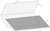
FIG. 2 is a schematic view of the diaphragm of the present invention folded in half;
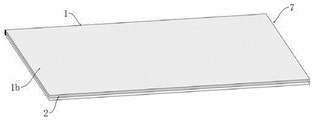
FIG. 3 is an assembly view of the diaphragm and water inlet grid of the present invention;
FIG. 4 is a schematic view of a water intake unit in the present invention;
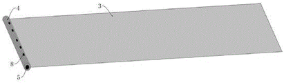
FIG. 5 is an assembly view of a central tube and water producing grid according to the present invention;
FIG. 6 is an assembly view of the water inlet unit and the water producing grid of the present invention;
FIG. 7 is a schematic view of a glue line of the sealant of the present invention;
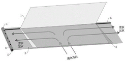
FIG. 8 is a schematic view showing the flow direction of concentrated water in the membrane unit according to the present invention;
FIG. 9 is a schematic view showing the flow direction of pure water in the membrane unit according to the present invention;
FIG. 10 is a schematic view showing the direction of flow of concentrated water in the membrane element according to the present invention;
FIG. 11 is a schematic view showing the direction of flow of pure water in the membrane element according to the present invention;
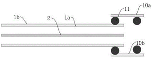
FIG. 12 is a schematic view of a membrane and a narrow strip membrane in example 2 of the present invention;
FIG. 13 is a schematic view of the sealant line coating in example 2 of the present invention;
fig. 14 is a sectional view of a water inlet unit in embodiment 2 of the present invention;
fig. 15 is a schematic structural view of a water inlet unit in embodiment 2 of the present invention.
The labels in the figures are: 1-a membrane; 1 a-a separation layer; 1 b-a support layer; 2-a water inlet grid; 3-producing a water grid; 4-a central tube; 5-a cavity; 6-sealing glue; 61-short glue lines; 62-long glue lines; 63-side glue line; 7-a water inlet unit; 8-a through hole; 9-membrane unit; 10-narrow strip membrane; 10 a-separation level; 10 b-a support deck; 11-sealant thread.
Detailed Description
The invention is further illustrated by the following figures and examples, which are not to be construed as limiting the invention.
Example 1: the high-efficiency membrane element, as shown in figure 1, comprises a central tube 4, wherein the inside of the central tube 4 is provided with a cavity 5, as shown in figures 5 and 7, the surface of the central tube 4 is provided with a plurality of through holes 8 communicated with the cavity 5; the system has at least one membrane page or leaf unit 9 on the surface of center tube 4 book, as shown in fig. 6, membrane page or leaf unit 9 includes the product water graticule mesh 3 that is connected with center tube 4, is equipped with into water unit 7 on the product water graticule mesh 3, as shown in fig. 2, it includes the diaphragm 1 of fifty percent discount to intake water unit 7, diaphragm 1 can be one of microfiltration membrane, milipore filter, nanofiltration membrane or reverse osmosis membrane, diaphragm 1 overlaps each other along the minor face fifty percent discount along the minor face, long limit, and the book direction of membrane page or leaf unit 9 is on a parallel with the direction of folding line, diaphragm 1 includes separation layer 1a and supporting layer 1b, and diaphragm 1 makes separation layer 1a inside and supporting layer 1b outwards with separation layer 1a symmetric folding, as shown in fig. 3 and fig. 4, is equipped with into water graticule mesh 2 in the diaphragm 1 of fifty percent discount, it sets up between the separation layer 1a of fifty percent discount and contacts to intake the grid 2.
The water inlet unit 7 is provided with a U-shaped sealant 6, the U-shaped sealant 6 comprises a long glue line 62 arranged along the long side of the opening side of the water inlet unit 7 and short glue lines 61 arranged along the short sides of the two sides of the water inlet unit 7, the two ends of the long glue line 62 are respectively connected with the tail ends of the two short glue lines 61 to form a U-shaped structure, and the directions of the U-shaped opening and the folding opening of the water inlet unit 7 are opposite; the water inlet unit folding structure further comprises side glue lines 63 which extend towards two sides from the folding position of the water inlet unit 7, wherein one side glue line 63 is positioned between the central pipe 4 and the water inlet unit 7, and the other side glue line 63 is positioned between the water inlet unit 7 and the tail end of the water producing grid 3; the sealant 6 is arranged on the surface of the water producing grid 3, and a sealant line of the sealant 6 is arranged at a position close to the edge of the water inlet unit 7.
As shown in any fig. 8 and fig. 9, the water flow enters from the opening side of the folded part of the water inlet unit 7, the concentrated water flows to both ends of the water grid 3, i.e. flows towards the central tube 4 or flows away from the central tube 4, while the pure water flows towards the opening direction of the U-shaped opening, when in actual use, as shown in fig. 10 and fig. 11, a membrane element with two end faces is formed after at least one membrane unit 9 is rolled on the surface of the central tube 4, the two end faces are a pure water outlet face and a water inlet face respectively, the folded opening side of the water inlet unit 7 corresponds to the gold water face, the opening side of the U-shaped structure corresponds to the pure water outlet face, the pure water outlet face is pure water, the water inlet face is filled with water, the concentrated water flows out from the periphery of the membrane element and one end of the central tube, specifically, the water flow enters from the water inlet face of the membrane element, the concentrated water flowing towards the central tube 4 enters into the cavity 5 through the through hole 8, and finally flows out from one end of the central tube 4, the concentrated water flowing away from the central tube 4 flows out from the periphery of the membrane element, while the pure water flows out from the pure water outlet surface of the membrane element, further, the water inlet position and the water outlet position of the concentrated water can be interchanged, namely, the water enters from the periphery of the membrane element and one end of the central tube, and the concentrated water flows out from one end surface of the membrane element.
In conclusion, in the invention, the membrane is firstly folded, and the membrane is rolled in a mode of being parallel to the direction of the fold line in the rolling process, so that the sealing between the pure water outlet side and the pure water inlet end is realized. And the water inlet is positioned in the middle of the membrane element, after water flow enters the flow channel, concentrated water can flow towards two directions simultaneously, the design of two pages of a conventional membrane element is realized while one page of membrane is rolled, the number of the flow channels of the membrane element is increased, the space of the membrane element is fully utilized, and the water purification efficiency is improved.
The production process of the high-efficiency membrane element is carried out according to the following steps:
s1: folding the membrane in a mode that short sides are folded in half and long sides are overlapped, wherein the separation layer of the membrane faces inwards, and the support layer faces outwards;
s2: inserting the water inlet grid into the folding space of the membrane, and enabling the water inlet grid to be in contact with the separation layer of the membrane to form a water inlet unit;
s3: taking a central pipe and at least one water producing grid net, fixing one end of one or more water producing grid nets with the central pipe, and arranging a water inlet unit on each water producing grid net to form a membrane unit;
s4: sealant is applied to the surface of the water producing grid along the long edge and the short edges at the two sides of the opening side of the folding part of the water inlet unit, and the sealant is applied to the two ends of the water producing grid at the folding part of the water inlet unit;
s5: and (3) rolling one or more membrane leaf units on the central pipe, wherein the rolling direction is parallel to the folding line direction, and cutting off the redundant parts on the end surfaces of the two sides to prepare the membrane element.
Example 2: when two independent membrane sheets 1 are used for manufacturing the water inlet unit 7, as shown in fig. 12, since glue cannot be directly applied to the separation layer 1a of the membrane sheet 1, and the glue can cause the separation layer 1a to be peeled off, thereby causing the performance to be damaged, in order to realize that pure water is discharged from the side surface of the membrane element in the rolling direction, it is necessary to realize sealing on the long side in the rolling direction, and to isolate water production and water inlet, therefore, in this embodiment, as shown in fig. 13, narrow membrane sheets 10 of the same material or similar materials are respectively adhered to the support layers 1b at the edges of the two independent membrane sheets 1, and sealing glue lines 11 are respectively coated on the support layer surfaces 10b of the narrow membrane sheets 10 at positions opposite to the membrane sheets 1 and at positions extending out, so that the support layer surfaces 10b of the two narrow membrane sheets 10 are inward, and the separation layer surfaces 10a are outward, thereby realizing sealing at the edges of the two membrane sheets 1 in a successive manner, the concrete connection mode is shown as the attached figure 14, and the manufactured water inlet unit 7 is shown as the attached figure 15; through the operation, the scene that the independent membrane 1 is used for manufacturing the water inlet unit 7 can be met.
Claims (10)
1. The high-efficiency membrane element comprises a central tube (4), wherein a cavity (5) is formed inside the central tube (4), and a plurality of through holes (8) communicated with the cavity (5) are formed in the surface of the central tube (4); the method is characterized in that: the surface of center tube (4) is rolled up and is made there is at least one membrane page or leaf unit (9), and membrane page or leaf unit (9) are equipped with into water unit (7) including producing water graticule mesh (3) that are connected with center tube (4) on producing water graticule mesh (3), and it includes diaphragm (1) of fifty percent discount to intake unit (7), is equipped with into water graticule mesh (2) in diaphragm (1) of fifty percent discount, is equipped with sealed glue (6) of U type structure on unit (7) of intaking.
2. The high efficiency membrane element of claim 1, wherein: the membrane sheet (1) comprises a separation layer (1 a) and a support layer (1 b), the membrane sheet (1) is symmetrically folded with the separation layer (1 a) so that the separation layer (1 a) faces inwards and the support layer (1 b) faces outwards; the water inlet grid (2) is arranged between the folded separation layers (1 a) and is in contact with the folded separation layers.
3. The high efficiency membrane element of claim 2, wherein: the membrane (1) is folded along the short edge, the long edges are mutually overlapped, and the rolling direction of the membrane leaf unit (9) is parallel to the direction of the folding line.
4. The high efficiency membrane element of claim 1, wherein: the membrane (1) can be one of a microfiltration membrane, an ultrafiltration membrane, a nanofiltration membrane or a reverse osmosis membrane.
5. The high efficiency membrane element of claim 1, wherein: the U-shaped structure sealant (6) comprises a long glue line (62) arranged along the long edge of the opening side of the water inlet unit (7) and short glue lines (61) arranged along the short edges of the two sides of the water inlet unit (7), and the two ends of the long glue line (62) are connected with the tail ends of the two short glue lines (61) respectively to form the U-shaped structure.
6. The high efficiency membrane element of claim 5, wherein: the water producing grid is characterized by further comprising side glue lines (63) which start to extend to two sides from the folded position of the water inlet unit (7), wherein one side glue line (63) is positioned between the central pipe (4) and the water inlet unit (7), and the other side glue line (63) is positioned between the water inlet unit (7) and the tail end of the water producing grid (3).
7. The high efficiency membrane element of claim 5, wherein: the opening direction of the U-shaped structure is opposite to the folding opening direction of the water inlet unit (7).
8. The high efficiency membrane element of claim 5, wherein: the sealant (6) is arranged on the surface of the water producing grid net (3), and the sealant line of the sealant (6) is arranged at a position close to the edge of the water inlet unit (7).
9. The high efficiency membrane element of claim 5, wherein: the membrane element with two end faces is formed after at least one membrane leaf unit (9) is rolled on the surface of the central tube (4), the two end faces are a pure water outlet face and a pure water inlet face respectively, pure water flows out of the pure water outlet face, water enters the water inlet face, and concentrated water flows out of the periphery of the membrane element and one end of the central tube.
10. The process for producing a high efficiency membrane element according to any one of claims 1 to 9, wherein the process is carried out by the steps of:
s1: folding the membrane in a mode that short sides are folded in half and long sides are overlapped, wherein the separation layer of the membrane faces inwards, and the support layer faces outwards;
s2: inserting the water inlet grid into the folding space of the membrane, and enabling the water inlet grid to be in contact with the separation layer of the membrane to form a water inlet unit;
s3: taking a central pipe and at least one water producing grid net, fixing one end of one or more water producing grid nets with the central pipe, and arranging a water inlet unit on each water producing grid net to form a membrane unit;
s4: sealant is applied to the surface of the water producing grid along the long side and the short sides at the two sides of the opening side of the folding position of the water inlet unit, and the sealant is applied to the two ends of the water producing grid at the folding position of the water inlet unit;
s5: and (3) rolling one or more membrane leaf units on the central pipe, wherein the rolling direction is parallel to the folding line direction, and cutting off the redundant parts on the end surfaces of the two sides to prepare the membrane element.
Priority Applications (8)
| Application Number | Priority Date | Filing Date | Title |
|---|---|---|---|
| CN202210702040.5A CN114849480A (en) | 2022-06-21 | 2022-06-21 | High-efficiency membrane element and production process |
| CN202310401638.5A CN117883979A (en) | 2022-06-21 | 2023-04-07 | Short flow passage membrane element and filter element |
| CN202320819899.4U CN219272688U (en) | 2022-06-21 | 2023-04-07 | Short flow passage membrane element and filter element |
| CN202320831928.9U CN219580269U (en) | 2022-06-21 | 2023-04-07 | Cross-flow filtering membrane element and filter element |
| CN202321119047.0U CN220257700U (en) | 2022-06-21 | 2023-05-10 | Raw water local diversion film element and filter element |
| CN202310528579.8A CN116474568A (en) | 2022-06-21 | 2023-05-10 | Raw water local diversion film element and filter element |
| PCT/CN2023/101266 WO2023246740A1 (en) | 2022-06-21 | 2023-06-20 | Short flow channel membrane element and filter |
| PCT/CN2023/101267 WO2023246741A1 (en) | 2022-06-21 | 2023-06-20 | Raw-water partial flow guide membrane element and filter element |
Applications Claiming Priority (1)
| Application Number | Priority Date | Filing Date | Title |
|---|---|---|---|
| CN202210702040.5A CN114849480A (en) | 2022-06-21 | 2022-06-21 | High-efficiency membrane element and production process |
Publications (1)
| Publication Number | Publication Date |
|---|---|
| CN114849480A true CN114849480A (en) | 2022-08-05 |
Family
ID=82626202
Family Applications (6)
| Application Number | Title | Priority Date | Filing Date |
|---|---|---|---|
| CN202210702040.5A Pending CN114849480A (en) | 2022-06-21 | 2022-06-21 | High-efficiency membrane element and production process |
| CN202320819899.4U Active CN219272688U (en) | 2022-06-21 | 2023-04-07 | Short flow passage membrane element and filter element |
| CN202320831928.9U Active CN219580269U (en) | 2022-06-21 | 2023-04-07 | Cross-flow filtering membrane element and filter element |
| CN202310401638.5A Pending CN117883979A (en) | 2022-06-21 | 2023-04-07 | Short flow passage membrane element and filter element |
| CN202321119047.0U Active CN220257700U (en) | 2022-06-21 | 2023-05-10 | Raw water local diversion film element and filter element |
| CN202310528579.8A Pending CN116474568A (en) | 2022-06-21 | 2023-05-10 | Raw water local diversion film element and filter element |
Family Applications After (5)
| Application Number | Title | Priority Date | Filing Date |
|---|---|---|---|
| CN202320819899.4U Active CN219272688U (en) | 2022-06-21 | 2023-04-07 | Short flow passage membrane element and filter element |
| CN202320831928.9U Active CN219580269U (en) | 2022-06-21 | 2023-04-07 | Cross-flow filtering membrane element and filter element |
| CN202310401638.5A Pending CN117883979A (en) | 2022-06-21 | 2023-04-07 | Short flow passage membrane element and filter element |
| CN202321119047.0U Active CN220257700U (en) | 2022-06-21 | 2023-05-10 | Raw water local diversion film element and filter element |
| CN202310528579.8A Pending CN116474568A (en) | 2022-06-21 | 2023-05-10 | Raw water local diversion film element and filter element |
Country Status (2)
| Country | Link |
|---|---|
| CN (6) | CN114849480A (en) |
| WO (1) | WO2023246741A1 (en) |
Families Citing this family (1)
| Publication number | Priority date | Publication date | Assignee | Title |
|---|---|---|---|---|
| WO2023246740A1 (en) * | 2022-06-21 | 2023-12-28 | 杭州苏博瑞驰科技有限公司 | Short flow channel membrane element and filter |
Citations (4)
| Publication number | Priority date | Publication date | Assignee | Title |
|---|---|---|---|---|
| CN205095658U (en) * | 2015-11-16 | 2016-03-23 | 艾欧史密斯(南京)水处理产品有限公司 | Film element |
| WO2018036063A1 (en) * | 2016-08-26 | 2018-03-01 | 佛山市顺德区美的饮水机制造有限公司 | Spiral wound reverse osmosis membrane element, membrane wound method thereof and reverse osmosis water purifier |
| CN109499376A (en) * | 2018-11-30 | 2019-03-22 | 佛山市云米电器科技有限公司 | A kind of wound membrane filter core and filtration system |
| CN113083020A (en) * | 2019-12-23 | 2021-07-09 | 广东美的白色家电技术创新中心有限公司 | Reverse osmosis filter element and end cover thereof |
Family Cites Families (7)
| Publication number | Priority date | Publication date | Assignee | Title |
|---|---|---|---|---|
| JP6056479B2 (en) * | 2011-12-02 | 2017-01-11 | 東レ株式会社 | Separation membrane element and method for producing separation membrane element |
| KR101741775B1 (en) * | 2015-03-13 | 2017-06-15 | 주식회사 피코그램 | assembly of RO sheet and RO filter |
| CN106076123B (en) * | 2016-08-22 | 2019-04-12 | 厦门建霖健康家居股份有限公司 | A kind of big flow long-life coiled reverse osmosis membrane element |
| CN207126384U (en) * | 2017-07-25 | 2018-03-23 | 艾欧史密斯(南京)水处理产品有限公司 | Filter core and its membrane component |
| CN108421415A (en) * | 2018-05-16 | 2018-08-21 | 南京帝膜净水材料开发有限公司 | A kind of wound membrane element |
| CN109999671A (en) * | 2019-04-01 | 2019-07-12 | 厦门百霖净水科技有限公司 | A kind of wound membrane structure and preparation method thereof improving reverse-osmosis membrane element flux |
| CN213824201U (en) * | 2020-05-19 | 2021-07-30 | 厦门百霖净水科技有限公司 | Reverse osmosis membrane filter core |
-
2022
- 2022-06-21 CN CN202210702040.5A patent/CN114849480A/en active Pending
-
2023
- 2023-04-07 CN CN202320819899.4U patent/CN219272688U/en active Active
- 2023-04-07 CN CN202320831928.9U patent/CN219580269U/en active Active
- 2023-04-07 CN CN202310401638.5A patent/CN117883979A/en active Pending
- 2023-05-10 CN CN202321119047.0U patent/CN220257700U/en active Active
- 2023-05-10 CN CN202310528579.8A patent/CN116474568A/en active Pending
- 2023-06-20 WO PCT/CN2023/101267 patent/WO2023246741A1/en unknown
Patent Citations (4)
| Publication number | Priority date | Publication date | Assignee | Title |
|---|---|---|---|---|
| CN205095658U (en) * | 2015-11-16 | 2016-03-23 | 艾欧史密斯(南京)水处理产品有限公司 | Film element |
| WO2018036063A1 (en) * | 2016-08-26 | 2018-03-01 | 佛山市顺德区美的饮水机制造有限公司 | Spiral wound reverse osmosis membrane element, membrane wound method thereof and reverse osmosis water purifier |
| CN109499376A (en) * | 2018-11-30 | 2019-03-22 | 佛山市云米电器科技有限公司 | A kind of wound membrane filter core and filtration system |
| CN113083020A (en) * | 2019-12-23 | 2021-07-09 | 广东美的白色家电技术创新中心有限公司 | Reverse osmosis filter element and end cover thereof |
Also Published As
| Publication number | Publication date |
|---|---|
| CN219580269U (en) | 2023-08-25 |
| CN116474568A (en) | 2023-07-25 |
| CN220257700U (en) | 2023-12-29 |
| CN219272688U (en) | 2023-06-30 |
| WO2023246741A1 (en) | 2023-12-28 |
| CN117883979A (en) | 2024-04-16 |
Similar Documents
| Publication | Publication Date | Title |
|---|---|---|
| AU2014223490B2 (en) | Improved spiral wound element construction | |
| US20120103891A1 (en) | Multi-leaf reverse osmosis element | |
| JPH10137558A (en) | Spiral separation membrane element and its production | |
| CN114849480A (en) | High-efficiency membrane element and production process | |
| WO2021051705A1 (en) | Roll-type reverse osmosis membrane element and water purification system | |
| CN110508138B (en) | Method for manufacturing roll type reverse osmosis membrane element | |
| CN213408252U (en) | High-flow-rate roll-type membrane filter element and water purifier comprising same | |
| CN218795111U (en) | Roll type reverse osmosis membrane element and water purifier with same | |
| CN104226113A (en) | Reverse osmosis membrane filter element and water treatment equipment with reverse osmosis membrane filter element | |
| CN217698705U (en) | Steady flow type flow channel membrane unit and filter element | |
| CN106390751A (en) | RO membrane vortex flow element and production method thereof | |
| CN110357216B (en) | Tandem double-water-quality membrane element and processing method thereof | |
| CN114849482A (en) | Flow stabilizing type flow channel membrane element and production process | |
| JP2022533831A (en) | Entrance features of spiral-wound elements | |
| CN212188610U (en) | Membrane module, filter element group spare and water purification unit | |
| CN210528540U (en) | Tandem double-water film element | |
| CN217939767U (en) | Split type high-efficiency membrane unit and filter element | |
| CN114849483B (en) | Membrane element for water in and out in same direction and production process | |
| CN211255368U (en) | Double-membrane water flow non-parallel type filter element device and water purifier | |
| CN217795522U (en) | Splicing type membrane unit and filter element | |
| CN217698706U (en) | Integrated efficient membrane unit and filter element | |
| CN210752126U (en) | Roll type reverse osmosis membrane element and water purification system | |
| CN217939766U (en) | Composite film rolling unit and filter element | |
| CN212687635U (en) | Membrane module, filter element group spare and water purification unit | |
| JP2022543640A (en) | Preferred flow paths for spiral-wound elements |
Legal Events
| Date | Code | Title | Description |
|---|---|---|---|
| PB01 | Publication | ||
| PB01 | Publication | ||
| SE01 | Entry into force of request for substantive examination | ||
| SE01 | Entry into force of request for substantive examination | ||
| WD01 | Invention patent application deemed withdrawn after publication | ||
| WD01 | Invention patent application deemed withdrawn after publication |
Application publication date: 20220805 |